DE102021104516A1 - Instrument for a robotic operating system - Google Patents
Instrument for a robotic operating systemDownload PDFInfo
- Publication number
- DE102021104516A1 DE102021104516A1DE102021104516.9ADE102021104516ADE102021104516A1DE 102021104516 A1DE102021104516 A1DE 102021104516A1DE 102021104516 ADE102021104516 ADE 102021104516ADE 102021104516 A1DE102021104516 A1DE 102021104516A1
- Authority
- DE
- Germany
- Prior art keywords
- inner shaft
- coupling element
- instrument
- shaft
- proximal end
- Prior art date
- Legal status (The legal status is an assumption and is not a legal conclusion. Google has not performed a legal analysis and makes no representation as to the accuracy of the status listed.)
- Pending
Links
Images


Classifications
- A—HUMAN NECESSITIES
- A61—MEDICAL OR VETERINARY SCIENCE; HYGIENE
- A61B—DIAGNOSIS; SURGERY; IDENTIFICATION
- A61B17/00—Surgical instruments, devices or methods
- A—HUMAN NECESSITIES
- A61—MEDICAL OR VETERINARY SCIENCE; HYGIENE
- A61B—DIAGNOSIS; SURGERY; IDENTIFICATION
- A61B17/00—Surgical instruments, devices or methods
- A61B17/00234—Surgical instruments, devices or methods for minimally invasive surgery
- A—HUMAN NECESSITIES
- A61—MEDICAL OR VETERINARY SCIENCE; HYGIENE
- A61B—DIAGNOSIS; SURGERY; IDENTIFICATION
- A61B17/00—Surgical instruments, devices or methods
- A61B17/28—Surgical forceps
- A61B17/29—Forceps for use in minimally invasive surgery
- A—HUMAN NECESSITIES
- A61—MEDICAL OR VETERINARY SCIENCE; HYGIENE
- A61B—DIAGNOSIS; SURGERY; IDENTIFICATION
- A61B34/00—Computer-aided surgery; Manipulators or robots specially adapted for use in surgery
- A61B34/30—Surgical robots
- A—HUMAN NECESSITIES
- A61—MEDICAL OR VETERINARY SCIENCE; HYGIENE
- A61B—DIAGNOSIS; SURGERY; IDENTIFICATION
- A61B34/00—Computer-aided surgery; Manipulators or robots specially adapted for use in surgery
- A61B34/70—Manipulators specially adapted for use in surgery
- A—HUMAN NECESSITIES
- A61—MEDICAL OR VETERINARY SCIENCE; HYGIENE
- A61B—DIAGNOSIS; SURGERY; IDENTIFICATION
- A61B90/00—Instruments, implements or accessories specially adapted for surgery or diagnosis and not covered by any of the groups A61B1/00 - A61B50/00, e.g. for luxation treatment or for protecting wound edges
- A61B90/08—Accessories or related features not otherwise provided for
- B—PERFORMING OPERATIONS; TRANSPORTING
- B25—HAND TOOLS; PORTABLE POWER-DRIVEN TOOLS; MANIPULATORS
- B25J—MANIPULATORS; CHAMBERS PROVIDED WITH MANIPULATION DEVICES
- B25J9/00—Programme-controlled manipulators
- B25J9/0009—Constructional details, e.g. manipulator supports, bases
- A—HUMAN NECESSITIES
- A61—MEDICAL OR VETERINARY SCIENCE; HYGIENE
- A61B—DIAGNOSIS; SURGERY; IDENTIFICATION
- A61B17/00—Surgical instruments, devices or methods
- A61B2017/00017—Electrical control of surgical instruments
- A61B2017/00137—Details of operation mode
- A—HUMAN NECESSITIES
- A61—MEDICAL OR VETERINARY SCIENCE; HYGIENE
- A61B—DIAGNOSIS; SURGERY; IDENTIFICATION
- A61B34/00—Computer-aided surgery; Manipulators or robots specially adapted for use in surgery
- A61B34/30—Surgical robots
- A61B2034/302—Surgical robots specifically adapted for manipulations within body cavities, e.g. within abdominal or thoracic cavities
Landscapes
- Health & Medical Sciences (AREA)
- Surgery (AREA)
- Life Sciences & Earth Sciences (AREA)
- Engineering & Computer Science (AREA)
- Molecular Biology (AREA)
- Public Health (AREA)
- Heart & Thoracic Surgery (AREA)
- Medical Informatics (AREA)
- Nuclear Medicine, Radiotherapy & Molecular Imaging (AREA)
- Animal Behavior & Ethology (AREA)
- General Health & Medical Sciences (AREA)
- Biomedical Technology (AREA)
- Veterinary Medicine (AREA)
- Robotics (AREA)
- Mechanical Engineering (AREA)
- Oral & Maxillofacial Surgery (AREA)
- Pathology (AREA)
- Ophthalmology & Optometry (AREA)
- Surgical Instruments (AREA)
Abstract
Translated fromGermanDescription
Translated fromGermanDie Erfindung betrifft ein Instrument für ein robotisches Operationssystem, welches ein Gehäuse umfasst sowie einen äußeren Schaft, welcher an einem distalen Ende mit einem Effektor und an einem proximalen Ende mit dem Gehäuse verbunden ist. Die Verbindung ist dabei rotatorisch, so dass der äußere Schaft um eine Achse - seine Längsachse - relativ gegenüber dem Gehäuse rotieren kann. Die rotatorische Verbindung erfolgt dabei über ein fest mit dem äußeren Schaft verbundenes erstes Koppelelement. Das Instrument umfasst außerdem einen ersten inneren Schaft, welcher teilweise innerhalb des äußeren Schaftes angeordnet und relativ zum äußeren Schaft beweglich gelagert ist. Bei der Relativbewegung kann es sich um eine Rotation oder eine Translation handeln. Der erste innere Schaft ist an einem distalen Ende mit dem Effektor und an einem proximalen Ende fest mit einem zweiten Koppelelement verbunden.The invention relates to an instrument for a robotic operating system, which comprises a housing and an outer shaft which is connected to an effector at a distal end and to the housing at a proximal end. The connection is rotatory, so that the outer shaft can rotate about an axis—its longitudinal axis—relative to the housing. The rotational connection takes place via a first coupling element that is firmly connected to the outer shaft. The instrument also includes a first inner shaft partially disposed within the outer shaft and mounted for movement relative to the outer shaft. The relative movement can be a rotation or a translation. The first inner shaft is firmly connected to the effector at a distal end and to a second coupling element at a proximal end.
Ein solches Instrument für die minimal-invasive Chirurgie wird beispielsweise in der
Im Stand der Technik sind bereits verschiedene Instrumente bekannt, welche zu diesem Zweck Dichtungen aufweisen. In der
In der
In der
In der
Die
In der
Aufgabe der Erfindung ist es, ein Instrument, wie es eingangs beschrieben wurde, dahingehend weiterzuentwickeln, dass ein Eindringen von Körperflüssigkeiten und/oder Gewebe des Patienten in den Bereich der Antriebseinheit möglichst effizient verhindert wird, wobei an einem bestehenden Instrument möglichst wenig Änderungen vorgenommen werden sollen, um den Herstellungsprozess nicht modifizieren zu müssen; so soll z.B. auf das Anbringen zusätzlicher Nuten oder Aufnahmen für Dichtringe verzichtet werden können, um insbesondere bereits vorhandene Instrumenten-Antriebseinheiten, an welche die Instrumente angekoppelt werden, weiter verwenden zu können.The object of the invention is to further develop an instrument, as described at the outset, such that the penetration of body fluids and/or tissue of the patient into the area of the drive unit is prevented as efficiently as possible, with as few changes as possible being made to an existing instrument , in order not to have to modify the manufacturing process; for example, it should be possible to dispense with the attachment of additional grooves or receptacles for sealing rings, in particular in order to be able to continue using existing instrument drive units to which the instruments are coupled.
Diese Aufgabe wird bei einem Instrument der eingangs beschriebenen Art dadurch gelöst, dass das erste Koppelelement den ersten inneren Schaft in einem ersten Übergangsbereich am proximalen Ende des äußeren Schafts umschließt, und ein erstes Dichtungselement den ersten inneren Schaft umschließt und gegen den äußeren Schaft abdichtet. Das Dichtungselement - beispielsweise eine Hülse oder ein Ring - ist dabei im Bereich des ersten Koppelelements angeordnet. Als flexible, dehnbare Hülse von ausreichender Länge kann das erste Dichtungselement beispielsweise teilweise das erste Koppelelement und teilweise den ersten inneren Schaft umschließen. Die Hülse kann auf das erste Koppelelement und den ersten inneren Schaft bei der Montage aufgezogen werden, ohne dass weitere Mittel zur Befestigung der Hülse nötig wären. Die Abdichtung erfolgt fluiddicht, d.h. gegen den Durchtritt von Flüssigkeiten.This object is achieved with an instrument of the type described above in that the first coupling element encloses the first inner shaft in a first transition area at the proximal end of the outer shaft, and a first sealing element encloses the first inner shaft and seals it against the outer shaft. The sealing element - for example a sleeve or a ring - is arranged in the area of the first coupling element. As a flexible, expandable sleeve of sufficient length, the first sealing element can, for example, partially enclose the first coupling element and partially enclose the first inner shaft. The sleeve can be slipped onto the first coupling element and the first inner shaft during assembly without the need for additional means for fastening the sleeve. The seal is fluid-tight, ie against the passage of liquids.
Je länger die Hülse entlang der Längsachse des ersten inneren Schaftes ist, desto besser ist der Dichtungseffekt; andererseits kann dies die Relativbewegung des ersten inneren Schaftes zum äußeren Schaft - bei der es sich um eine rotatorische Bewegung handeln kann, bevorzugt aber um eine translatorische Bewegung handelt - erschweren: Auch wenn diese Bewegung motorisch angetrieben erfolgt, so kann dies zu Reibungsverlusten zwischen dem erste inneren Schaft und dem ersten Dichtungselement führen, die unter Umständen eine genaue Positionierung behindern und im schlimmsten Fall auch zu einem Reißen der Hülse führen können. Um dies zu vermeiden, ist es zweckmäßig, das erste Dichtungselement mit einer geringstmöglichen axialen Ausdehnung, beispielsweise als Dichtungsring auszugestalten, wobei dann aber auf andere Weise dafür gesorgt werden muss, dass das erste Dichtungselement den ersten inneren Schaft gegen den äußeren Schaft abdichtet.The longer the sleeve along the longitudinal axis of the first inner shaft, the better the sealing effect; on the other hand, this can make the relative movement of the first inner shaft to the outer shaft - which can be a rotational movement, but is preferably a translational movement - more difficult: Even if this movement is motor-driven, this can lead to friction losses between the first inner shaft and the first sealing element, which under certain circumstances impede precise positioning and, in the worst case, can also lead to a rupture of the sleeve. In order to avoid this, it is expedient to design the first sealing element with the smallest possible axial extent, for example as a sealing ring, but then it must be ensured in a different way that the first sealing element seals the first inner shaft against the outer shaft.
Dabei macht man sich zunutze, dass das erste Koppelelement fest mit dem äußeren Schaft verbunden ist, gleichzeitig aber den ersten inneren Schaft im ersten Übergangsbereich so umschließt, dass der erste innere Schaft ungehindert die translatorische oder rotatorische Relativbewegung gegenüber dem äußeren Schaft durchführen kann. Dies eröffnet im Wesentlichen zwei Möglichkeiten, die sich grundsätzlich auch kombinieren lassen, um den Abdichtungseffekt zu erhöhen: In einer ersten Alternative ist das erste Dichtungselement an einem proximalen Ende des ersten Koppelelements fixiert. Diese Fixierung kann stoffschlüssig erfolgen, so dass keine gesonderten Halterungen für das erste Dichtungselement, was vorzugsweise als Dichtungsring ausgestaltet ist, erforderlich sind. Das erste Dichtungselement umschließt dann also den ersten inneren Schaft am proximalen Ende des ersten Koppelelements und verhindert so, dass Flüssigkeit oder Gewebe in das Innere des Instruments tritt und die Antriebseinheit kontaminiert. In einer zweiten Alternative ist das erste Dichtungselement innerhalb des ersten Koppelelements im ersten Übergangsbereich angeordnet. Dabei wird es axial von dem proximalen Ende des äußeren Schaftes und dem ersten Koppelelement fixiert. In diesem Fall macht man sich zu Nutze, dass der Radius des äußeren Schaftes größer als der des ersten inneren Schaftes ist und somit das erste Koppelelement im Bereich des äußeren Schaftes einen größeren Innendurchmesser aufweisen muss, als es im Bereich des - vom ersten Koppelelement ebenfalls teilweise umschlossenen - ersten inneren Schaftes nötig ist. Idealerweise bildet der Bereich, in dem sich der Innendurchmesser des ersten Koppelelements verjüngt, eine Kante und damit eine - sich vorzugsweise in radialer Richtung mit einer Flächennormalen in axialer Richtung erstreckende - Anschlagfläche für das erste Dichtungselement. Dort kann das erste Dichtungselement ebenfalls stoffschlüssig fixiert werden. Vorzugsweise wird es aber auch vom proximalen Ende des äußeren Schafts, der mit dem ersten Koppelelement fest verbunden ist, fixiert, so dass es zwischen dem proximalen Ende des äußeren Schafts und der Anschlagfläche formschlüssig fixiert, eingeklemmt ist und auf eine stoffschlüssige Verbindung verzichtet werden kann. Dies erleichtert die MontageThis makes use of the fact that the first coupling element is firmly connected to the outer shaft, but at the same time encloses the first inner shaft in the first transition area in such a way that the first inner shaft can perform the translational or rotational movement relative to the outer shaft unhindered. This essentially opens up two possibilities, which can in principle also be combined in order to increase the sealing effect: In a first alternative, the first sealing element is fixed to a proximal end of the first coupling element. This fixation can take place in a materially bonded manner, so that no separate holders are required for the first sealing element, which is preferably designed as a sealing ring. The first sealing element then encloses the first inner shaft at the proximal end of the first coupling element and thus prevents liquid or tissue from entering the interior of the instrument and contaminating the drive unit. In a second alternative, the first sealing element is arranged within the first coupling element in the first transition area. It is fixed axially by the proximal end of the outer shaft and the first coupling element. In this case, use is made of the fact that the radius of the outer shaft is larger than that of the first inner shaft and the first coupling element must therefore have a larger inner diameter in the area of the outer shaft than it has in the area of the - also partly from the first coupling element enclosed - first inner shaft is necessary. Ideally, the area in which the inner diameter of the first coupling element tapers forms an edge and thus a stop surface for the first sealing element, preferably extending in the radial direction with a surface normal in the axial direction. There, the first sealing element can also be fixed in a materially bonded manner. However, it is preferably also fixed by the proximal end of the outer shaft, which is firmly connected to the first coupling element, so that it is positively fixed and clamped between the proximal end of the outer shaft and the stop surface and a material connection can be dispensed with. This makes assembly easier
In einer besonders bevorzugten Ausgestaltung der ersten Alternative ist zwischen dem ersten Koppelelement und dem zweiten Koppelelement ein in der Regel mit dem Gehäuse verbundenes erstes Führungselement angeordnet. In diesem wird der erste innere Schaft geführt, was dessen Lagerung zusätzlicher Stabilität verleiht. Dabei ist das erste Dichtungselement zwischen dem ersten Koppelelement und dem ersten Führungselement angeordnet und wird von diesen axial fixiert. Eine Relativbewegung zwischen dem ersten Koppelelement und dem ersten Führungselement ist nicht möglich und der Abstand zwischen beiden entlang der Längsachse des Instruments bzw. der Schäfte ist so bemessen, dass das erste Dichtungselement genau zwischen das erste Koppelelement und das erste Führungselement passt; die axiale Fixierung ist also auch in diesem Fall formschlüssig, so dass auf eine stoffschlüssige Verbindung verzichtet werden kann. Das erste Dichtungselement kann als Dichtungsring ausgebildet sein, beispielsweise als O-Ring oder als X-Ring. Das erste Dichtungselement kann Silikon enthalten oder vollständig aus Silikon gefertigt sein, wobei das Silikon bevorzugt biokompatibel ist. Das erste Dichtungselement ist bevorzugt ringförmig mit rechteckigem Querschnitt und weist an seinem inneren Umfang - der Bohrung - und/oder an einer Stirnfläche, die in Richtung des abzudichtenden Abschnitts des Instruments, hier also an der zum ersten Koppelelement weisenden Stirnfläche, umlaufend geschlossene, im Querschnitt zahnförmige Dichtlamellen auf, welche flexibel und elastisch deformierbar sind, wodurch der Dichtungseffekt verstärkt und eine bessere Anpassung an Oberflächen mit einer höheren Rauigkeit erreicht wird.In a particularly preferred embodiment of the first alternative, a first guide element, which is generally connected to the housing, is arranged between the first coupling element and the second coupling element. The first inner shaft is guided in this, which gives its storage additional stability. The first sealing element is arranged between the first coupling element and the first guide element and is axially fixed by them. A relative movement between the first coupling element and the first guide element is not possible and the distance between the two along the longitudinal axis of the instrument or the shafts is dimensioned such that the first sealing element fits exactly between the first coupling element and the first guide element; the axial fixation is also positive in this case, so that an integral connection can be dispensed with. The first sealing element can be designed as a sealing ring, for example an O-ring or an X-ring. The first sealing element can contain silicone or be made entirely of silicone, with the silicone preferably being biocompatible. The first sealing element is preferably ring-shaped with a rectangular cross section and has on its inner circumference - the bore - and/or on an end face which is closed in cross section in the direction of the section of the instrument to be sealed, i.e. here on the end face pointing towards the first coupling element tooth-shaped sealing lamellae, which are flexible and elastically deformable, whereby the sealing effect is reinforced and a better adaptation to surfaces with a higher roughness is achieved.
In einer weiteren Ausgestaltung umfasst das Instrument außerdem einen zweiten inneren Schaft, welcher teilweise innerhalb des ersten inneren Schafts angeordnet ist, wobei der zweite innere Schaft sowohl relativ zum äußeren Schaft als auch relativ zum ersten inneren Schaft beweglich gelagert ist - vorzugsweise rotierbar, aber auch eine translatorisch bewegliche Lagerung ist denkbar. An einem distalen Ende ist der zweite innere Schaft ebenfalls mit dem Effektor verbunden und an einem proximalen Ende fest mit einem dritten Koppelelement. Dabei umschließt das zweite Koppelelement den zweiten inneren Schaft in einem zweiten Übergangsbereich am proximalen Ende des ersten inneren Schafts, und ein zweites Dichtungselement umschließt den zweiten inneren Schaft und dichtet ihn gegen den ersten inneren Schaft fluiddicht ab. Das zweite Dichtungselement ist dabei bevorzugt analog wie das erste Dichtungselement ausgestaltet, jedoch in der Regel mit geringfügig kleinerem Durchmesser.In a further embodiment, the instrument also comprises a second inner shaft, which is partially arranged inside the first inner shaft, the second inner shaft being movably mounted both relative to the outer shaft and also relative to the first inner shaft—preferably rotatably, but translationally movable mounting is also conceivable. The second inner shaft is also connected to the effector at a distal end and fixed to a third coupling element at a proximal end. The second coupling element encloses the second inner shaft in a second transition area at the proximal end of the first inner shaft, and a second sealing element encloses the second inner shaft and seals it against the first inner shaft in a fluid-tight manner. The second sealing element is preferably configured analogously to the first sealing element, but usually with a slightly smaller diameter.
In einer ersten Alternative ist das zweite Dichtungselement dabei an einem proximalen Ende des zweiten Koppelelements fixiert, beispielsweise stoffschlüssig. Eine andere Möglichkeit besteht darin, das zweite Dichtungselement innerhalb des zweiten Koppelelements im zweiten Übergangsbereich anzuordnen, wo es dann axial von dem proximalen Ende des ersten inneren Schaftes und dem zweiten Koppelelement fixiert ist, so wie es vorangehend bereits für das erste Dichtungselement beschrieben wurde; diese Ausführungen lassen sich analog auf das zweite Dichtungselement übertragen. Beide Ausgestaltungen für die Anordnung des zweiten Dichtungselements können grundsätzlich auch kombiniert werden, so dass zwei Dichtungselemente verwendet werden, was die Abdichtung gegen den Durchtritt von Fluiden weiter verbessert.In a first alternative, the second sealing element is fixed to a proximal end of the second coupling element, for example with a material bond. Another possibility consists in arranging the second sealing element within the second coupling element in the second transition region, where it is then fixed axially by the proximal end of the first inner shaft and the second coupling element, as has already been described above for the first sealing element; these statements can be transferred analogously to the second sealing element. In principle, both configurations for the arrangement of the second sealing element can also be combined, so that two sealing elements are used, which further improves the sealing against the passage of fluids.
In einer bevorzugten Ausgestaltung des Instruments in der ersten Alternative für das zweite Dichtungselement, bei der der erste innere Schaft relativ zum äußeren Schaft translatorisch entlang der Achse verschiebbar gelagert ist, und bei der vorteilhaft auf eine stoffschlüssige Fixierung des zweiten Dichtungselements verzichtet werden kann, umfasst das Instrument ein erstes axiales Rückstellfederelement mit einem proximalen und einem distalen Ende, welches auf das zweite Koppelelement bei dessen translatorischer Verschiebung aus einer Grundstellung heraus eine dieser Verschiebung entgegengesetzte Federkraft ausübt. Das zweite Dichtungselement ist dabei zwischen dem zweiten Koppelelement und dem ersten axialen Rückstellfederelement angeordnet und von diesen eingespannt. Diese Einspannung erfolgt bevorzugt kraft- und gleichzeitig formschlüssig; auf eine zusätzliche Fixierung kann verzichtet werden. Auf diese Weise wird außerdem ein Anpressdruck auf das zweite Dichtungselement gegen das zweite Koppelelement ausgeübt, wodurch die Abdichtung gegen den Durchtritt von Flüssigkeiten weiter verbessert wird. Eine besonders bevorzugte Ausgestaltung dieser Variante sieht ein zweites Führungselement vor, welches zwischen dem zweiten Koppelelement und dem dritten Koppelelement angeordnet ist und in welchem der zweite innere Schaft geführt wird. Das proximale Ende des ersten axialen Rückstellfederelements liegt dabei am zweiten Führungselement oder ist optional daran - beispielsweise stoffschlüssig - befestigt. Durch das zweite Führungselement wird somit die Stabilität und Sicherheit des Instruments bei der Verwendung erhöht.In a preferred embodiment of the instrument in the first alternative for the second sealing element, in which the first inner shaft is mounted so that it can be displaced translationally along the axis relative to the outer shaft, and in which it is advantageously possible to dispense with a materially bonded fixation of the second sealing element Instrument has a first axial restoring spring element with a proximal and a distal end, which exerts a spring force opposite to this displacement on the second coupling element during its translational displacement from a basic position. The second sealing element is arranged between the second coupling element and the first axial restoring spring element and clamped by them. This clamping preferably takes place in a non-positive manner and at the same time in a form-fitting manner; additional fixation can be dispensed with. In this way, a contact pressure is also exerted on the second sealing element against the second coupling element, as a result of which the seal against the passage of liquids is further improved. A particularly preferred embodiment of this variant provides a second guide element which is arranged between the second coupling element and the third coupling element and in which the second inner shaft is guided. The proximal end of the first axial restoring spring element lies on the second guide element or is optionally attached to it—for example, in a materially bonded manner. The second guide element thus increases the stability and safety of the instrument during use.
In einer weiteren Ausgestaltung des Instruments für Effektoren mit mehr Freiheitsgraden umfasst das Instrument einen dritten inneren Schaft, welcher teilweise innerhalb des zweiten inneren Schafts angeordnet und relativ zum äußeren Schaft, zum ersten inneren Schaft und zum zweiten inneren Schaft beweglich gelagert ist. An einem distalen Ende ist der dritte innere Schaft mit dem Effektor und an einem proximalen Ende fest mit einem vierten Koppelelement verbunden. Dabei umschließt das vierte Koppelelement den zweiten inneren Schaft in einem dritten Übergangsbereich am proximalen Ende des zweiten inneren Schafts. Das vierte Koppelelement selbst ist am proximalen Ende durch einteilige Fertigung dicht bzw. durch ein stoffschlüssig fixiertes Abschlusselement abgedichtet. Ein drittes Dichtungselement ist außerdem an einem distalen Ende des vierten Koppelelements fixiert, umschließt den zweiten inneren Schaft und dichtet diesen gegen den dritten inneren Schaft fluiddicht ab. Auch hier kann das dritte Dichtungselement stoffschlüssig mit dem distalen Ende des vierten Koppelelements verbunden sein. Die bereits oben für das erste Dichtungselement gemachten Ausführungen, was dessen spezielle Ausgestaltung betrifft, lassen sich analog auch auf das dritte Dichtungselement übertragen und sollen hier nicht wiederholt werden. Durch die stoffschlüssige Verbindung des dritten Dichtungselements mit dem vierten Koppelelement lässt sich ebenfalls auf zusätzliche Fixierungsmittel verzichten. Die freiliegende Anordnung behindert die Herstellung einer reversiblen Verbindung mit einer Instrumenten-Antriebseinheit durch einfaches Einklicken nicht.In a further embodiment of the instrument for effectors with more degrees of freedom, the instrument comprises a third inner shaft which is partially arranged inside the second inner shaft and is movably mounted relative to the outer shaft, the first inner shaft and the second inner shaft. The third inner shaft is firmly connected to the effector at a distal end and to a fourth coupling element at a proximal end. The fourth coupling element encloses the second inner shaft in a third transition area at the proximal end of the second inner shaft. The fourth coupling element itself is sealed at the proximal end by being manufactured in one piece or by a closure element that is fixed in a materially bonded manner. A third sealing element is also fixed at a distal end of the fourth coupling element, encloses the second inner shaft and seals it against the third inner shaft in a fluid-tight manner. Here, too, the third sealing element can be cohesively connected to the distal end of the fourth coupling element. The statements made above for the first sealing element, as far as its special configuration is concerned, can also be applied analogously to the third sealing element and should not be repeated here. Due to the integral connection of the third sealing element to the fourth coupling element, additional fixing means can also be dispensed with. The exposed arrangement does not impede making a reversible connection to an instrument drive unit by simply clicking it in.
In einer zweckmäßigen Ausgestaltung ist der dritte innere Schaft relativ zum äußeren Schaft, relativ zum ersten inneren Schaft und relativ zum zweiten inneren Schaft translatorisch entlang der Achse verschiebbar gelagert. In diesem Fall umfasst das Instrument besonders bevorzugt ein zweites axiales Rückstellfederelement, welches mit einem distalen Ende am dritten Koppelelement anliegt oder an diesem - beispielsweise stoffschlüssig oder formschlüssig - befestigt ist und auf das vierte Koppelelement bei dessen translatorischer Verschiebung aus einer Grundstellung heraus eine dieser Verschiebung entgegengesetzte Federkraft ausübt. Das dritte Dichtungselement ist dann zwischen dem distalen Ende des vierten Koppelelements und dem proximalen Ende des zweiten axialen Rückstellfederelements angeordnet und von diesen analog zum zweiten Dichtungselement eingespannt. Die Einspannung erfolgt aufgrund der Federkraft in der Regel zumindest kraftschlüssig und formschlüssig; das zweite - und analog das erste - axiale Rückstellfederelement wird in der Regel unter Vorspannung montiert. Eine zusätzliche Fixierung, beispielsweise mittels Stoffschluss, ist daher nicht notwendig, was die Herstellung erleichtert.In an expedient embodiment, the third inner shaft is mounted so as to be translationally displaceable along the axis relative to the outer shaft, relative to the first inner shaft and relative to the second inner shaft. In this case, the instrument particularly preferably comprises a second axial restoring spring element, which bears with a distal end on the third coupling element or is attached to it - for example materially or positively - and one of these displacements is applied to the fourth coupling element during its translational displacement from a basic position exerts opposite spring force. The third sealing element is then arranged between the distal end of the fourth coupling element and the proximal end of the second axial restoring spring element and is clamped by them analogously to the second sealing element. The clamping takes place due to the spring force, as a rule, at least in a non-positive and positive manner; the second—and similarly the first—axial return spring element is generally mounted under pretension. An additional fixation, for example by means of a material connection, is therefore not necessary, which simplifies production.
In dem dritten inneren Schaft ist zweckmäßig mindestens ein Betätigungselement für den Effektor angeordnet, welches beispielsweise als Zugseil oder Zugdraht ausgebildet ist.At least one actuating element for the effector is expediently arranged in the third inner shaft, which is designed, for example, as a pull cable or pull wire.
Es versteht sich, dass die vorstehend genannten und die nachstehend noch zu erläuternden Merkmale nicht nur in den angegebenen Kombinationen, sondern auch in anderen Kombinationen oder in Alleinstellung einsetzbar sind, ohne den Rahmen der vorliegenden Erfindung zu verlassen.It goes without saying that the features mentioned above and those still to be explained below can be used not only in the specified combinations, but also in other combinations or on their own, without departing from the scope of the present invention.
Nachfolgend wird die Erfindung anhand von Ausführungsbeispielen unter Bezugnahme auf die beigefügten Zeichnungen, die ebenfalls erfindungswesentliche Merkmale offenbaren, noch näher erläutert. Diese Ausführungsbeispiele dienen lediglich der Veranschaulichung und sind nicht als einschränkend auszulegen. Beispielsweise ist eine Beschreibung eines Ausführungsbeispiels mit einer Vielzahl von Elementen oder Komponenten nicht dahingehend auszulegen, dass alle diese Elemente oder Komponenten zur Implementierung notwendig sind. Vielmehr können andere Ausführungsbeispiele auch alternative Elemente und Komponenten, weniger Elemente oder Komponenten oder zusätzliche Elemente oder Komponenten enthalten. Elemente oder Komponenten verschiedener Ausführungsbespiele können miteinander kombiniert werden, sofern nichts anderes angegeben ist. Modifikationen und Abwandlungen, welche für eines der Ausführungsbeispiele beschrieben werden, können auch auf andere Ausführungsbeispiele anwendbar sein. Zur Vermeidung von Wiederholungen werden gleiche oder einander entsprechende Elemente in verschiedenen Figuren mit gleichen Bezugszeichen bezeichnet und nicht mehrmals erläutert. Es zeigen:
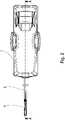
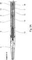
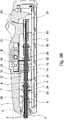
1 eine Perspektivansicht eines Instruments für eine robotisches Operationssystem,2 das Instrument aus1 in einer verkürzten Darstellung von oben,3A , einen Schnitt durch die Instrumentenspitze,3B einen Schnitt durch den Korpus des Instruments,4 einen Ausschnitt des Korpus aus3B , und5 eine Perspektivansicht eines Dichtelements.
1 a perspective view of an instrument for a robotic operating system,2 the instrument off1 in an abbreviated view from above,3A , a cut through the instrument tip,3B a cut through the body of the instrument,4 a section of the body3B , and5 a perspective view of a sealing element.
Das Instrument umfasst außerdem einen ersten inneren Schaft 7, welcher auch als Schwenkrohrschaft bezeichnet wird. Der erste innere Schaft 7 ist teilweise innerhalb des äußeren Schaftes 2 angeordnet und relativ zum äußeren Schaft 2 beweglich - hier translatorisch entlang der Längsachse verschiebbar - gelagert. In anderen Ausführungen insbesondere mit anderen Effektoren kann der erste innere Schaft 7 um die Längsachse rotierbar gelagert sein. Auch der erste innere Schaft 7 ist an einem distalen Ende mit dem Effektor 3 verbunden. An einem proximalen Ende ist der erste innere Schaft 7 fest mit einem zweiten Koppelelement 8 verbunden. Der erste innere Schaft 7 kann in Längsrichtung des äußeren Schaftes 2, welcher auch als Instrumentenschaft bezeichnet wird, translatorisch bewegt werden, um den Instrumentenkopf, d.h. den Effektor 3, zu verschwenken. Das erste Koppelelement 4 dient bezüglich der translatorischen Bewegung des ersten inneren Schaftes 7 auch als Führung. Der Effektor 3 steht dazu über einen Zughebel 9 mit dem distalen Ende des ersten inneren Schaftes 7 in Verbindung. Wird der erste innere Schaft 7 translatorisch in Richtung des proximalen Endes gezogen, so wird der Effektor 3 verschwenkt und ein Biegeelement 10 seitlich gebogen. Zur Übertragung der translatorischen Bewegung von der Antriebseinheit auf den ersten inneren Schaft 7 dient ein erstes Eingriffelement 11 am zweiten Koppelelement 8, mit welchem der erste innere Schaft 7 fest verbunden ist. Die Rückstellung in die Ausgangslage mit axialer Ausrichtung des Effektors 3 wird durch ein erstes axiales Rückstellfederelement 12 erleichtert; das erste axiale Rückstellfederelement 12 übt auf das zweite Koppelelement 8 bei dessen translatorischer Verschiebung aus einer Grundstellung heraus eine dieser Verschiebung entgegengesetzte Federkraft aus. Zwischen dem ersten Koppelelement 4 und dem zweiten Koppelelement 8 ist ein optionales erstes Führungselement 24 angeordnet, in welchem der erste innere Schaft 7 zusätzlich geführt wird.The instrument also includes a first
Teilweise innerhalb des ersten inneren Schaftes 7 ist ein zweiter innerer Schaft 13 angeordnet, der ebenfalls relativ zum äußeren Schaft 2 und zum ersten inneren Schaft 7 beweglich gelagert ist. Im hier gezeigten Beispiel ist der zweite innere Schaft 13 relativ zum äußeren Schaft 2 und zum ersten inneren Schaft 7 um die Achse, d. h. die Längsachse des Instrumentenschafts bzw. des äußeren Schaftes 2, rotierbar gelagert, der zweite innere Schaft 13 wird in diesem Fall auch als Drehrohrschaft bezeichnet. In anderen Ausgestaltungen des Instruments bzw. der Effektoren kann der zweite innere Schaft 13 auch translatorisch beweglich sein. Der zweite innere Schaft 13 ist an einem distalen Ende mit dem Effektor 3 und an einem proximalen Ende fest mit einem dritten Koppelelement 14 verbunden. Die Verbindung ist vorzugsweise stoffschlüssig, kann aber auch formschlüssig und/oder kraftschlüssig erfolgen. Das zweite Koppelelement 8 umschließt dabei den zweiten inneren Schaft 13 in einem zweiten Übergangsbereich 29 am proximalen Ende des ersten inneren Schaftes 7, wobei die Beweglichkeit des zweiten inneren Schaftes 13 gegenüber dem zweiten Koppelelement 8 bzw. dem ersten inneren Schaft 7 nicht beeinträchtigt wird. Das Umschließen erfolgt möglichst passgenau, um ein Eindringen von Flüssigkeit oder Gewebe in das Gehäuse 1 möglich zu verhindern. Gleiches gilt in Bezug auf das Umschließen des ersten inneren Schaftes 7 durch das erste Koppelelement 4. Um den zweiten inneren Schaft 12 rotatorisch zu bewegen, ist am dritten Koppelelement 14 ein weiteres rotatorisch angetriebenes Element, hier ein zweiter Zahnkranz 15 ausgebildet, der durch einen entsprechenden Antrieb in der Instrumenten-Antriebseinheit in Rotation um die Längsachse versetzt werden kann. Der zweite innere Schaft 13 ist mit der Schraubenfeder 10 drehfest verbunden und überträgt die rotatorische Bewegung auf diese. Zwischen dem zweiten Koppelelement 8 und dem dritten Koppelelement 14 ist ein optionales zweites Führungselement 30 angeordnet, in welchem der zweite innere Schaft 13 geführt wird. Ein proximales Ende des ersten axialen Rückstellfederelements 12 liegt dabei am zweiten Führungselement 30 an oder ist daran befestigt, um dem ersten axialen Rückstellfederelement 12 einen entsprechenden Halt zu geben.A second
Schließlich umfasst das Instrument auch einen dritten inneren Schaft 16, welcher teilweise innerhalb des zweiten inneren Schaftes 13 angeordnet ist und relativ zum äußeren Schaft 2, zum ersten inneren Schaft 7 und zum zweiten inneren Schaft 13 beweglich gelagert ist. Im hier gezeigten Beispiel ist der dritte innere Schaft 16 relativ zu den anderen Schäften 2, 7 und 13 translatorisch entlang der Achse, d. h. der Längsachse des äußeren Schaftes 2 bzw. der Instrumentenlängsachse, verschiebbar gelagert. In Abhängigkeit von einem gewählten Effektor kann der dritte innere Schaft 16 abweichend auch rotatorisch gelagert sein. Auch können gegebenenfalls einer oder mehrere der inneren Schäfte 7, 13 oder 16 wegfallen.Finally, the instrument also includes a third
Der dritte innere Schaft 16 ist an einem distalen Ende ebenfalls mit dem Effektor 3 und an einem proximalen Ende fest mit einem vierten Koppelelement 17 verbunden; die Verbindung ist vorzugsweise stoffschlüssig, kann aber auch auf andere Weise erfolgen. Das vierte Koppelelement 17 umschließt den zweiten inneren Schaft 13 in einem dritten Übergangsbereich 31 am proximalen Ende des zweiten inneren Schaftes 13. Die von der Instrumenten-Antriebseinheit erzeugte translatorische Bewegung wird über ein am vierten Koppelelement 17 ausgebildetes zweites Eingriffelement 18 auf dieses übertragen. Das zweite Eingriffelement 18 ist hier als umlaufende Außennut ausgebildet, deren sich in radialer Richtung erstreckende Begrenzungsflächen als Anschlagflächen für den Antrieb dienen. Innerhalb des auch als Greifrohrschaft bezeichneten dritten inneren Schaftes 16 befindet sich ein Betätigungselement für den Effektor 3, hier ein Zugdraht 19, mit dem eine Greif- oder Schneidbewegung des Effektors 3 ausgelöst werden kann. Über die Instrumenten-Antriebseinheit wird der Zugdraht 19 zum Öffnen der Schenkel des Greifelements des Effektors 3 in die distale Richtung verschoben. Mittels eines Hebelelements 20 lässt sich das Greifelement manuell öffnen, beispielsweise bei einem Ausfall des Systems oder bei Vorliegen anderer Fehler, die eine Öffnung über die Instrumenten-Antriebseinheit mittels der Steuerung verhindern. Das Hebelelement wird dazu im Uhrzeigersinn um eine Drehachse, die senkrecht zur Zeichenebene steht, bewegt, und stößt gegen ein Abschlusselement 21, welches stoffschlüssig mit dem vierten Koppelelement 17 verbunden ist und dieses fluiddicht abdichtet. Der Zugdraht 19 ist hier im Abschlusselement 21 befestigt, kann aber auch direkt am vierten Koppelelement 17 befestigt sein. Zum Schließen des Greifelements wird der Zugdraht 19 in die entgegengesetzte, proximale Richtung bewegt. Um einen sicheren und festen Griff zu gewährleisten, wird auf den Zugdraht 19 bzw. das vierte Koppelelement 17 zusätzlich von einem zweiten axialen Rückstellefederelement 22 eine Schubkraft auf das vierte Koppelelement 17 ausgeübt; beim Öffnen wird das zweite axiale Rückstellfederelement 22 gestaucht. Im vorliegenden Beispiel ist das zweite axiale Rückstellefederelement 22 an dem axial fest positionierten dritten Koppelelement 14 befestigt.The third
Der äußere Schaft 2, der erste innere Schaft 7, der zweite innere Schaft 13 und der dritte innere Schaft 16 sind dabei koaxial angeordnet und untereinander so gekoppelt, dass eine Drehbewegung übertragbar ist. Wird also der äußere Schaft 2 gedreht, so drehen sich der erste innere Schaft 7, der zweite innere Schaft 13 und der dritte innere Schaft 16 gleichermaßen, so dass ihre relativen Stellungen zueinander gleichbleiben. Wird hingegen nur der zweite innere Schaft 13 rotiert, so drehte sich nur der dritte innere Schaft 16 mit.The
Mit passgenauen Abmessungen der Koppelelemente 4, 8, 14, 17 in den Übergangsbereichen, wo sie jeweils den nächsten innenliegenden Schaft umschließen, lässt sich der Übertritt von Körperflüssigkeiten und Gewebe in das Gehäuse 1 zwar im Wesentlichen unterdrücken, jedoch nicht vollständig ausschließen. Um den Übertritt von Körperflüssigkeiten in das Gehäuse 1 effektiv zu vermeiden, umfasst das Instrument daher mehrere Dichtungselemente. Ein erstes Dichtungselement 23 umschließt den ersten inneren Schaft 7 und dichtet diesen gegen den äußeren Schaft 2 ab. Im vorliegenden Beispiel wird der erste innere Schaft 7 im ersten Führungselement 24 geführt, welches zwischen dem ersten Koppelelement 4 und dem zweiten Koppelelement 8 angeordnet ist. Das erste Dichtungselement 23 ist zwischen dem ersten Koppelelement 4 und dem ersten Führungselement 24 angeordnet. Es wird von diesen beiden Elementen axial fixiert, da das erste Führungselement 24 fest mit dem Gehäuse 1 verbunden ist und auch das erste Koppelelement 4 in axialer Richtung fixiert ist. Diese Positionierung des ersten Dichtungselements 23 ermöglicht eine einfache Nachrüstung bestehender Systeme sowie eine Modifikation des Herstellungsprozesses, ohne dass sämtliche Werkzeuge für die Fertigung, beispielsweise Spritzgusswerkzeuge, modifiziert werden müssten. Das Dichtungselement 23 ist ringförmig ausgebildet. In dem in
Alternativ kann auf das erste Führungselement 24 auch verzichtet werden und das erste Dichtungselement 23 kann direkt an einem proximalen Ende des ersten Koppelelements 4 fixiert werden, beispielsweise stoffschlüssig. In einer weiteren alternativen Ausgestaltung kann das erste Dichtungselement 23 auch innerhalb des ersten Koppelelements 4 in einem ersten Übergangsbereich 26 angeordnet sein. Dort wird es axial vom proximalen Ende des äußeren Schaftes 2 und vom ersten Koppelelement 4 fixiert. In keinem der Fälle ist eine wesentliche Modifikation der Werkzeuge und des Herstellungsprozesses für das Instrument notwendig, abgesehen davon, dass in einem zusätzlichen Schritt das erste Dichtungselement 23 integriert werden muss.Alternatively, the
Das erste Dichtungselement 23 dichtet den ersten inneren Schaft 7 gegen den äußeren Schaft 2 ab. Zur Abdichtung des zweiten inneren Schaftes 13 gegen den ersten inneren Schaft 7 ist ein zweites Dichtungselement 27 vorgesehen, welches den zweiten inneren Schaft 13 umschließt. Zur Abdichtung des zweiten inneren Schaftes 13 gegen den dritten inneren Schaft 16 ist ein drittes Dichtungselement 28 vorgesehen, welches ebenfalls den zweiten inneren Schaft 13 umschließt, da es am distalen Ende des vierten Koppelelements 17 angeordnet ist. Alle drei Dichtungselemente 23, 27 und 28 können ähnlich aufgebaut sein. Als Material kommt beispielsweise Silikon, insbesondere biokompatibles Silikon, infrage.The
Das zweite Dichtungselement 27 ist hier zwischen dem ersten axialen Rückstellfederelement 12 und dem zweiten Koppelelement 8 angeordnet und wird von diesen eingespannt, eine zusätzliche Fixierung am ersten axialen Rückstellfederelement 12 und/oder am zweiten Koppelelement 8 ist nicht nötig, jedoch möglich. Bei einer stoffschlüssigen Verbindung muss darauf geachtet werden, einen Klebstoff zu verwenden, welcher nicht zu einem Aushärten des Materials, aus dem die Dichtungselemente gefertigt sind, führt, da dies die Abdichtungswirkung verringern könnte. Vorzugsweise werden die Dichtungselemente daher, sofern eine stoffschlüssige Fixierung vorgesehen ist, an denjenigen Seiten fixiert, an denen kein Flüssigkeitsdurchtritt zu erwarten ist. Im Falle des zweiten Dichtungselements 27 käme daher insbesondere eine Fixierung am ersten axialen Rückstellfederelement 12 infrage, und im Falle des dritten Dichtungselements 28 eine Fixierung am zweiten axialen Rückstellfederelement 22. Alternativ kann das zweite Dichtungselement 27 auch ausschließlich an einem proximalen Ende des zweiten Koppelelements 8 fixiert sein. In einer weiteren alternativen Ausgestaltung kann das zweite Dichtungselement 27 auch innerhalb des zweiten Koppelelements 8 im zweiten Übergangsbereich 29 angeordnet sein, wo es axial von dem proximalen Ende des ersten inneren Schaftes 7 und dem zweiten Koppelelement 8 fixiert ist.The
Das vorangehend beschriebene Instrument ist gegenüber bekannten Instrumenten ähnlicher Bauart aufgrund der Verwendung von Dichtungselementen besser abgedichtet. Die Anordnung der Dichtungselemente kann in bereits bestehende Instrumentenkonfigurationen ohne wesentliche Änderungen übernommen werden. Durch die Verwendung von mehreren Dichtungselementen und deren Verteilung entlang der Längsachse an den Übergangsstellen bzw. in den Übergangsbereichen zwischen den Schäften können sämtliche Stellen, an denen Möglichkeit für einen Flüssigkeitsaustritt in das Gehäuse besteht, effektiv abgedichtet werden. Auf eine zusätzliche Befestigung der Dichtungselemente kann verzichtet werden, da diese in ihren axialen Positionen durch bereits vorhandene Rückstellfederelemente, Koppelelemente und/oder Führungselemente fixiert sind. Sowohl bei rotatorischer als auch bei translatorischer Bewegung können die Schäfte unter den Dichtungselementen gleiten, so dass diese nicht ungewollt verschoben werden.The instrument described above is better sealed than known instruments of a similar design due to the use of sealing elements. The arrangement of the sealing elements can be adopted in existing instrument configurations without any significant changes. By using several sealing elements and distributing them along the longitudinal axis at the transition points or in the transition areas between the shafts, all points at which there is a possibility of liquid escaping into the housing can be effectively sealed. There is no need for an additional fastening of the sealing elements, since these are fixed in their axial positions by return spring elements, coupling elements and/or guide elements that are already present. The shafts can slide under the sealing elements both in the case of rotary and in the case of translational movement, so that they are not displaced unintentionally.
BezugszeichenlisteReference List
- 11
- GehäuseHousing
- 22
- äußerer Schaftouter shaft
- 33
- Effektoreffector
- 44
- erstes Koppelelementfirst coupling element
- 55
- Lagerwarehouse
- 66
- erster Zahnkranzfirst sprocket
- 77
- erster innerer Schaftfirst inner shaft
- 88th
- zweites Koppelelementsecond coupling element
- 99
- Zughebelpull lever
- 1010
- Biegeelementbending element
- 1111
- erstes Eingriffelementfirst engagement element
- 1212
- erstes axiales Rückstellfederelementfirst axial return spring element
- 1313
- zweiter innerer Schaftsecond inner shaft
- 1414
- drittes Koppelelementthird coupling element
- 1515
- zweiter Zahnkranzsecond sprocket
- 1616
- dritter innerer Schaftthird inner shaft
- 1717
- viertes Koppelelementfourth coupling element
- 1818
- zweites Eingriffelementsecond engaging element
- 1919
- Zugdrahtpull wire
- 2020
- Hebelelementlever element
- 2121
- Abschlusselementfinal element
- 2222
- zweites axiales Rückstellfederelementsecond axial return spring element
- 2323
- erstes Dichtungselementfirst sealing element
- 2424
- erstes Führungselementfirst guiding element
- 2525
- Dichtlamellesealing lamella
- 2626
- erster Übergangsbereichfirst transition area
- 2727
- zweites Dichtungselementsecond sealing element
- 2828
- drittes Dichtungselementthird sealing element
- 2929
- zweiter Übergangsbereichsecond transition area
- 3030
- zweites Führungselementsecond guiding element
- 3131
- dritter Übergangsbereichthird transition area
ZITATE ENTHALTEN IN DER BESCHREIBUNGQUOTES INCLUDED IN DESCRIPTION
Diese Liste der vom Anmelder aufgeführten Dokumente wurde automatisiert erzeugt und ist ausschließlich zur besseren Information des Lesers aufgenommen. Die Liste ist nicht Bestandteil der deutschen Patent- bzw. Gebrauchsmusteranmeldung. Das DPMA übernimmt keinerlei Haftung für etwaige Fehler oder Auslassungen.This list of documents cited by the applicant was generated automatically and is included solely for the better information of the reader. The list is not part of the German patent or utility model application. The DPMA assumes no liability for any errors or omissions.
Zitierte PatentliteraturPatent Literature Cited
- DE 102014117408 A1 [0002]DE 102014117408 A1 [0002]
- US 2012/0209289 A1 [0003]US 2012/0209289 A1 [0003]
- US 7367973 B2 [0003]US 7367973 B2 [0003]
- US 2017/0290680 A1 [0003]US 2017/0290680 A1 [0003]
- US 2016/0193001 A1 [0004]US 2016/0193001 A1 [0004]
- DE 102007030856 B3 [0005]DE 102007030856 B3 [0005]
- US 2008/0065021 A1 [0006]US 2008/0065021 A1 [0006]
- WO 2019/072988 A1 [0006]WO 2019/072988 A1 [0006]
- US 2016/0175060 A1 [0007]US 2016/0175060 A1 [0007]
- US 2010/0168510 A1 [0008]US 2010/0168510 A1 [0008]
Claims (14)
Translated fromGermanPriority Applications (4)
| Application Number | Priority Date | Filing Date | Title |
|---|---|---|---|
| DE102021104516.9ADE102021104516A1 (en) | 2021-02-25 | 2021-02-25 | Instrument for a robotic operating system |
| EP22153710.3AEP4049608A1 (en) | 2021-02-25 | 2022-01-27 | Instrument for a robotic surgery system |
| US17/670,156US20220265375A1 (en) | 2021-02-25 | 2022-02-11 | Instrument for a robotic surgery system |
| CN202210168735.XACN114947998A (en) | 2021-02-25 | 2022-02-23 | Instrument for robotic surgical system |
Applications Claiming Priority (1)
| Application Number | Priority Date | Filing Date | Title |
|---|---|---|---|
| DE102021104516.9ADE102021104516A1 (en) | 2021-02-25 | 2021-02-25 | Instrument for a robotic operating system |
Publications (1)
| Publication Number | Publication Date |
|---|---|
| DE102021104516A1true DE102021104516A1 (en) | 2022-08-25 |
Family
ID=80121787
Family Applications (1)
| Application Number | Title | Priority Date | Filing Date |
|---|---|---|---|
| DE102021104516.9APendingDE102021104516A1 (en) | 2021-02-25 | 2021-02-25 | Instrument for a robotic operating system |
Country Status (4)
| Country | Link |
|---|---|
| US (1) | US20220265375A1 (en) |
| EP (1) | EP4049608A1 (en) |
| CN (1) | CN114947998A (en) |
| DE (1) | DE102021104516A1 (en) |
Citations (12)
| Publication number | Priority date | Publication date | Assignee | Title |
|---|---|---|---|---|
| US20080065021A1 (en) | 2006-09-07 | 2008-03-13 | Gyrus Medical Limited | Surgical instrument |
| US7367973B2 (en) | 2003-06-30 | 2008-05-06 | Intuitive Surgical, Inc. | Electro-surgical instrument with replaceable end-effectors and inhibited surface conduction |
| DE102007034577A1 (en) | 2007-07-13 | 2009-01-15 | Karl Storz Gmbh & Co. Kg | Medical instrument |
| DE102007030856B3 (en) | 2007-06-26 | 2009-04-09 | Aesculap Ag | Surgical instrument e.g. scissors, for minimally invasive surgical procedure in patient, has piston sections with outer diameter smaller than inner diameter of shaft, and sealing element everted by formation of rolled sealing section |
| US20100168510A1 (en) | 2008-12-30 | 2010-07-01 | Intuitive Surgical, Inc. | Surgical instruments with sheathed tendons |
| US20120209289A1 (en) | 2011-02-15 | 2012-08-16 | Intuitive Surgical Operations, Inc. | Seals and sealing methods for a surgical instrument having an articulated end effector actuated by a drive shaft |
| DE102014117408A1 (en) | 2014-11-27 | 2016-06-02 | avateramedical GmBH | Device for robotic surgery |
| US20160175060A1 (en) | 2013-08-15 | 2016-06-23 | Intuitive Surgical Operations, Inc. | Reusable surgical instrument with single-use tip and integrated tip cover |
| US20160193001A1 (en) | 2013-08-15 | 2016-07-07 | Intuitive Surgical Operations, Inc. | Instrument shaft for computer-assisted surgical system |
| DE102015117731A1 (en) | 2015-10-19 | 2017-04-20 | Karl Storz Gmbh & Co. Kg | Medical instrument |
| US20170290680A1 (en) | 2016-04-07 | 2017-10-12 | Howmedica Osteonics Corp. | Surgical insertion instruments |
| WO2019072988A1 (en) | 2017-10-13 | 2019-04-18 | Olympus Winter & Ibe Gmbh | WORK CHANNEL SEAL |
Family Cites Families (1)
| Publication number | Priority date | Publication date | Assignee | Title |
|---|---|---|---|---|
| KR101635698B1 (en)* | 2012-04-27 | 2016-07-08 | 쿠카 레보라토리즈 게엠베하 | Robotic surgery system and surgical instrument |
- 2021
- 2021-02-25DEDE102021104516.9Apatent/DE102021104516A1/enactivePending
- 2022
- 2022-01-27EPEP22153710.3Apatent/EP4049608A1/enactivePending
- 2022-02-11USUS17/670,156patent/US20220265375A1/ennot_activeAbandoned
- 2022-02-23CNCN202210168735.XApatent/CN114947998A/enactivePending
Patent Citations (12)
| Publication number | Priority date | Publication date | Assignee | Title |
|---|---|---|---|---|
| US7367973B2 (en) | 2003-06-30 | 2008-05-06 | Intuitive Surgical, Inc. | Electro-surgical instrument with replaceable end-effectors and inhibited surface conduction |
| US20080065021A1 (en) | 2006-09-07 | 2008-03-13 | Gyrus Medical Limited | Surgical instrument |
| DE102007030856B3 (en) | 2007-06-26 | 2009-04-09 | Aesculap Ag | Surgical instrument e.g. scissors, for minimally invasive surgical procedure in patient, has piston sections with outer diameter smaller than inner diameter of shaft, and sealing element everted by formation of rolled sealing section |
| DE102007034577A1 (en) | 2007-07-13 | 2009-01-15 | Karl Storz Gmbh & Co. Kg | Medical instrument |
| US20100168510A1 (en) | 2008-12-30 | 2010-07-01 | Intuitive Surgical, Inc. | Surgical instruments with sheathed tendons |
| US20120209289A1 (en) | 2011-02-15 | 2012-08-16 | Intuitive Surgical Operations, Inc. | Seals and sealing methods for a surgical instrument having an articulated end effector actuated by a drive shaft |
| US20160175060A1 (en) | 2013-08-15 | 2016-06-23 | Intuitive Surgical Operations, Inc. | Reusable surgical instrument with single-use tip and integrated tip cover |
| US20160193001A1 (en) | 2013-08-15 | 2016-07-07 | Intuitive Surgical Operations, Inc. | Instrument shaft for computer-assisted surgical system |
| DE102014117408A1 (en) | 2014-11-27 | 2016-06-02 | avateramedical GmBH | Device for robotic surgery |
| DE102015117731A1 (en) | 2015-10-19 | 2017-04-20 | Karl Storz Gmbh & Co. Kg | Medical instrument |
| US20170290680A1 (en) | 2016-04-07 | 2017-10-12 | Howmedica Osteonics Corp. | Surgical insertion instruments |
| WO2019072988A1 (en) | 2017-10-13 | 2019-04-18 | Olympus Winter & Ibe Gmbh | WORK CHANNEL SEAL |
Also Published As
| Publication number | Publication date |
|---|---|
| CN114947998A (en) | 2022-08-30 |
| EP4049608A1 (en) | 2022-08-31 |
| US20220265375A1 (en) | 2022-08-25 |
Similar Documents
| Publication | Publication Date | Title |
|---|---|---|
| DE19707373C1 (en) | Releasable connection of two tube shaft instruments or instrument parts | |
| EP2510887B1 (en) | Tool for a micro-surgical instrument | |
| EP1065979A1 (en) | Surgical instrument with a continuous hollow channel for another instrument | |
| DE102011007121A1 (en) | Handling device for a micro-invasive-surgical instrument | |
| EP2014246B1 (en) | Medical instrument | |
| EP2393435A1 (en) | Surgical instrument for detachably connecting a handpiece to a surgical tool | |
| DE102012008537A1 (en) | Surgical robot system has robot that is releasably fixed to instrument arrangement, and instrument interface that is arranged between drive unit and instrument | |
| DE102019102599A1 (en) | Endoscope with distal swivel mechanism and fine adjustment | |
| DE102011050193A1 (en) | Surgical instrument, surgical handpiece and surgical drive system | |
| DE102011007119A1 (en) | Handling device for a micro-invasive-surgical instrument | |
| EP2497433A1 (en) | Multiple trocar system | |
| EP1083834A1 (en) | Device for producing a transcutaneous access to a hollow viscus in the interior of the body | |
| EP2996586B1 (en) | Connection for a morcellator | |
| DE102021104516A1 (en) | Instrument for a robotic operating system | |
| DE102017123905A1 (en) | Working channel seal | |
| EP3158965B1 (en) | Medical instrument | |
| EP3173038B1 (en) | Shaft instrument | |
| DE102009037045A1 (en) | Tubular shaft of a surgical instrument | |
| EP3498198A1 (en) | Minimally invasive medical instrument | |
| EP4178466A1 (en) | Medical instrument | |
| DE102013207248A1 (en) | Instrument, in particular a medical endoscopic instrument or technoscope | |
| DE102015119691A1 (en) | Demountable surgical instrument | |
| EP3943024B1 (en) | Medical instrument | |
| EP3158956A1 (en) | Microsurgical instrument, handle and motor block for a microsurgical instrument | |
| DE102022107970A1 (en) | Flexible surgical tool with integrated bearing assembly |
Legal Events
| Date | Code | Title | Description |
|---|---|---|---|
| R163 | Identified publications notified | ||
| R083 | Amendment of/additions to inventor(s) | ||
| R082 | Change of representative | Representative=s name:GLEIM PETRI PATENT- UND RECHTSANWALTSPARTNERSC, DE | |
| R082 | Change of representative |