DE102020212976A1 - Wireless remote control system - Google Patents
Wireless remote control systemDownload PDFInfo
- Publication number
- DE102020212976A1 DE102020212976A1DE102020212976.2ADE102020212976ADE102020212976A1DE 102020212976 A1DE102020212976 A1DE 102020212976A1DE 102020212976 ADE102020212976 ADE 102020212976ADE 102020212976 A1DE102020212976 A1DE 102020212976A1
- Authority
- DE
- Germany
- Prior art keywords
- remote control
- charging station
- machine
- pairing
- paired
- Prior art date
- Legal status (The legal status is an assumption and is not a legal conclusion. Google has not performed a legal analysis and makes no representation as to the accuracy of the status listed.)
- Pending
Links
- 238000004891communicationMethods0.000claimsabstractdescription34
- 238000000034methodMethods0.000claimsdescription11
- 230000005540biological transmissionEffects0.000claimsdescription3
- 230000001939inductive effectEffects0.000claimsdescription2
- 230000006870functionEffects0.000description7
- 230000001965increasing effectEffects0.000description4
- 238000005516engineering processMethods0.000description3
- 239000000428dustSubstances0.000description2
- 238000004519manufacturing processMethods0.000description2
- 238000010079rubber tappingMethods0.000description2
- 238000003860storageMethods0.000description2
- 239000000853adhesiveSubstances0.000description1
- 230000033228biological regulationEffects0.000description1
- UQMRAFJOBWOFNS-UHFFFAOYSA-Nbutyl 2-(2,4-dichlorophenoxy)acetateChemical compoundCCCCOC(=O)COC1=CC=C(Cl)C=C1ClUQMRAFJOBWOFNS-UHFFFAOYSA-N0.000description1
- 238000004040coloringMethods0.000description1
- 230000001419dependent effectEffects0.000description1
- 230000005674electromagnetic inductionEffects0.000description1
- 238000007689inspectionMethods0.000description1
- 238000009434installationMethods0.000description1
- 230000010354integrationEffects0.000description1
- 239000012528membraneSubstances0.000description1
- 238000011056performance testMethods0.000description1
- 238000003825pressingMethods0.000description1
- 230000000007visual effectEffects0.000description1
Images


Classifications
- G—PHYSICS
- G08—SIGNALLING
- G08C—TRANSMISSION SYSTEMS FOR MEASURED VALUES, CONTROL OR SIMILAR SIGNALS
- G08C17/00—Arrangements for transmitting signals characterised by the use of a wireless electrical link
- G08C17/02—Arrangements for transmitting signals characterised by the use of a wireless electrical link using a radio link
- G—PHYSICS
- G08—SIGNALLING
- G08C—TRANSMISSION SYSTEMS FOR MEASURED VALUES, CONTROL OR SIMILAR SIGNALS
- G08C2201/00—Transmission systems of control signals via wireless link
- G08C2201/20—Binding and programming of remote control devices
Landscapes
- Engineering & Computer Science (AREA)
- Computer Networks & Wireless Communication (AREA)
- Physics & Mathematics (AREA)
- General Physics & Mathematics (AREA)
- Selective Calling Equipment (AREA)
Abstract
Translated fromGermanDescription
Translated fromGermanDie Erfindung betrifft ein drahtloses Fernbedienungssystem zur Bedienung von Kraftfahrzeugprüfständen und/oder Kraftfahrzeughebebühnen nach dem Oberbegriff von Anspruch 1.The invention relates to a wireless remote control system for operating motor vehicle test benches and/or motor vehicle lifting platforms according to the preamble of claim 1.
Im Bereich der Kraftfahrzeugwerkstätten, bei der Herstellung von Kraftfahrzeugen und bei der technischen Überprüfung von Kraftfahrzeugen kommen verbreitet Prüfstandsysteme zum Einsatz. Insbesondere werden Bremsanlagen von Kraftfahrzeugen mittels Bremsprüfständen geprüft.Test stand systems are widely used in motor vehicle workshops, in the manufacture of motor vehicles and in the technical inspection of motor vehicles. In particular, brake systems of motor vehicles are tested using brake testers.
Beim Einsatz von Bremsprüfständen gelten strenge Sicherheitsvorschriften. Verbreitet bestehen Bremsprüfstandsysteme daher aus einem Bremsprüfstand und einer durch Kabel damit verbundenen Fernsteuerung zur Bedienung des Bremsprüfstandes. Die sichere Zuordnung von Prüfstand und Fernsteuerung ist dabei durch das Verbindungskabel gewährleistet. Allerdings wird die Flexibilität hinsichtlich der Bedienung durch die Länge des Verbindungskabels eingeschränkt und es ist immer eine Fernbedienung mit einem Prüfstand verbunden.Strict safety regulations apply when using brake testers. Brake tester systems therefore commonly consist of a brake tester and a remote control connected to it by a cable for operating the brake tester. The connection cable ensures that the test bench and remote control are reliably assigned. However, the flexibility in terms of operation is limited by the length of the connection cable and a remote control is always connected to a test bench.
Es Aufgabe der Erfindung, ein Fernbedienungssystem bereitzustellen, das flexibel im Einsatz und sicher ist.It is the object of the invention to provide a remote control system that is flexible in use and safe.
Diese Aufgabe wird erfindungsgemäß durch ein drahtloses Fernbedienungssystem nach Anspruch 1, eine Fernbedienung nach Anspruch 11, eine Ladestation nach Anspruch 12, ein Bremsprüfstandsystem nach Anspruch 13 und ein Verfahren zum Ansteuern einer Maschine, insbesondere eines Bremsprüfstandsystems, nach Anspruch 14 gelöst. Besonders bevorzugte Ausführungsformen der Erfindung sind in den abhängigen Ansprüchen angegeben.This object is achieved according to the invention by a wireless remote control system according to claim 1, a remote control according to claim 11, a charging station according to
Das erfindungsgemäße drahtlose Fernbedienungssystem zum Bedienen einer Maschine, insbesondere eines Bremsprüfstandes für Kraftfahrzeuge und/oder Hebebühnen für Kraftfahrzeuge, weist zumindest eine Fernbedienung und zumindest eine Ladestation auf. Die Maschine kann aufweisen und/oder kann signaltechnisch mit einem Funkempfänger verbunden sein, der Signale, z.B. Steuersignale, von der Fernbedienung über eine Funkstrecke empfängt, die der Steuerung der Maschine dienen können. Die Ladestation(en) können ferner zum Aufladen eines Akkus der Fernbedienung eingerichtet sein. Zwischen der Ladestation und der Fernbedienung kann eine Nahfeldkommunikation vorgesehen sein, d.h. jede Ladestation und jede Fernbedienung kann bspw. einen NFC-Chip aufweisen. Mit anderen Worten können die Fernbedienung(en) und die Ladestation(en) jeweils bevorzugt eine Spule bzw. einen RFID-Transponder bzw. einen RFID-Transponder und ein Lesemittel aufweisen bzw. jeweils einen NFC-Chip.The wireless remote control system according to the invention for operating a machine, in particular a brake tester for motor vehicles and/or lifting platforms for motor vehicles, has at least one remote control and at least one charging station. The machine can have and/or can be signal-connected to a radio receiver which receives signals, e.g. control signals, from the remote control via a radio link, which can be used to control the machine. The charging station(s) can also be set up to charge a battery in the remote control. Near-field communication can be provided between the charging station and the remote control, i.e. each charging station and each remote control can have an NFC chip, for example. In other words, the remote control(s) and the charging station(s) can each preferably have a coil or an RFID transponder or an RFID transponder and a reading means or an NFC chip.
Die Fernbedienung(en) und die Ladestation(en) können mittels der NFC-Chips dazu eingerichtet sein, ein Pairing/Paaren durchzuführen, um eine Fernbedienung mittels der Nahfeldkommunikation mit einem Funkempfänger der Maschine (bzw. der mit der Maschine signaltechnisch verbunden ist) zu verbinden. Mit anderen Worten empfängt die Ladestation über die NFC Antenne die Fernbedienung und meldet das über bspw. eine serielle Schnittstelle an den Funkempfänger der Maschine bzw. dessen Steuerung(-seinheit). Danach ist der Funkempfänger mit der Fernbedienung gepairt.The remote control(s) and the charging station(s) can be set up using the NFC chips to perform a pairing(s) in order to connect a remote control to a radio receiver of the machine (or which is connected to the machine in terms of signals) by means of near-field communication associate. In other words, the charging station receives the remote control via the NFC antenna and reports this via a serial interface, for example, to the radio receiver of the machine or its control (unit). The radio receiver is then paired with the remote control.
Nach dem Pairing kann die Fernbedienung über eine Funkstrecke zu dem Funkempfänger die Maschine steuern bzw. Steuerbefehle kabellos übermitteln. Die Ladestation weist bevorzugt eine serielle Schnittstelle zu dem Funkempfänger der Maschine auf, um das Pairing durchzuführen. Nach dem Pairing ist der Funkempfänger bevorzugt derart eingerichtet, dass nur die Fernbedienung, mit der das Pairing durchgeführt wurde, valide Steuersignale an den Funkempfänger senden kann bzw. der Funkempfänger nur Steuersignale von der gepairten Fernbedienung aufnimmt/verarbeitet.After pairing, the remote control can control the machine or transmit control commands wirelessly via a radio link to the radio receiver. The charging station preferably has a serial interface to the machine's radio receiver in order to carry out the pairing. After the pairing, the radio receiver is preferably set up in such a way that only the remote control with which the pairing was carried out can send valid control signals to the radio receiver or the radio receiver only receives/processes control signals from the paired remote control.
Die Fernbedienung des drahtlosen Fernbedienungssystems dient insbesondere zum Ansteuern von Maschinen mit erhöhter Sicherheitsanforderung, wie z. B. Bremsprüfständen, Hebebühnen für Kraftfahrzeuge, Leistungsprüfstande, Tachoprüfstände und/oder Achsspieltester sowie sonstige Prüfgeräte. Bei der Ansteuerung eines Bremsprüfstandes ist es enorm wichtig, dass Klarheit über den Verbindungsstatus zwischen Fernbedienung und einer Steuerung des zu steuernden Bremsprüfstandes besteht, um Fehlbedienungen zu vermeiden. Die Ladestation der Fernbedienung ist bevorzugt in der Nähe oder an dem Bremsprüfstand angeordnet. Um eine besonders sichere Kommunikation zwischen der Fernbedienung und dem Bremsprüfstand zu erreichen, wird die Fernbedienung mittels der Ladestation über die Nahfeldkommunikation (NFC) und eine bevorzugt serielle Datenschnittstelle zu dem Funkempfänger der Maschine gepairt.The remote control of the wireless remote control system is used in particular to control machines with increased safety requirements such. B. brake testers, lifting platforms for motor vehicles, performance test benches, speedometer test benches and/or axle play testers and other test equipment. When controlling a brake tester, it is extremely important that there is clarity about the connection status between the remote control and a control of the brake tester to be controlled in order to avoid operating errors. The charging station for the remote control is preferably located near or at the brake tester. In order to achieve particularly secure communication between the remote control and the brake tester, the remote control is paired to the radio receiver of the machine using the charging station via near-field communication (NFC) and a preferably serial data interface.
Die Nahfeldkommunikation ist ein auf der RFID-Technik basierender internationaler Übertragungsstandard zum kontaktlosen Austausch von Daten per elektromagnetischer Induktion mittels loser gekoppelter Spulen über kurze Strecken von wenigen Zentimetern. Dabei sind in der Fernbedienung und der Ladestation jeweils Spulen angeordnet oder in einem von beiden ist beispielsweise ein RFID-Chip angeordnet, der vom anderen von beiden dann ausgelesen bzw. erkannt werden kann. Zum Pairing muss die Fernbedienung demnach in die Nähe der Ladestation gebracht werden und beispielsweise ein Pairing-Knopf an der Fernbedienung gedrückt werden. Nach dem Pairing kann die Fernbedienung den Bremsprüfstand über die Funkstrecke zu dem Funkempfänger steuern. Durch diese Zuordnung wird es möglich, dass mit einer Fernbedienung zwar mehrere Bremsprüfstände mit zugeordneten Ladestationen angesteuert werden können, es jedoch immer nur eine Fernbedienung geben kann, die zeitgleich mit einem Funkempfänger einer Maschine gepairt ist. Dadurch können mehrere Maschinen, insbesondere Bremsprüfstände, mit einer Fernbedienung gesteuert werden, jedoch aus Sicherheitsgründern nicht zeitgleich. Eine Fernbedienung eines Bremsprüfstandes, den der Bediener gar nicht ansteuern will, wird durch das Pairing verhindert. Mit anderen Worten können beispielsweise eine Vielzahl Fernbedienungen eingesetzt werden, bspw. kann jeder Mitarbeiter eine eigene verwenden, jedoch wird durch das dezidierte Pairing mit dem Funkempfänger komfortabel über die Ladestation sichergestellt, dass immer nur eine Fernbedienung mit einer Maschine bzw. dessen zugeordneten Funkempfänger kommunizieren kann. Eine Maschine kann somit nicht unbeabsichtigt von verschiedenen Fernbedienungen oder Personen gleichzeitig angesteuert werden.Near-field communication is an international transmission standard based on RFID technology for the contactless exchange of data via electromagnetic induction using loosely coupled coils over short distances of a few centimetres. Coils are arranged in the remote control and the charging station, or an RFID chip is arranged in one of them, for example, which can then be read or recognized by the other of the two. For pairing, the remote control must therefore be in the Be brought close to the charging station and, for example, press a pairing button on the remote control. After pairing, the remote control can control the brake tester via the radio link to the radio receiver. This assignment makes it possible that, although several brake testers with assigned charging stations can be controlled with one remote control, there can only ever be one remote control that is paired with a radio receiver of a machine at the same time. This means that several machines, especially brake testers, can be controlled with one remote control, but not at the same time for safety reasons. The pairing prevents remote control of a brake tester that the operator does not want to control at all. In other words, for example, a large number of remote controls can be used, e.g. each employee can use their own, but the dedicated pairing with the radio receiver conveniently ensures via the charging station that only one remote control can ever communicate with a machine or its assigned radio receiver . A machine can therefore not be unintentionally controlled by different remote controls or people at the same time.
Soll eine neue Fernbedienung mit einem bereits gepairten Funkempfänger/Maschine dazu verbunden werden, so muss zunächst die bereits gepairte Fernbedienung entpaart/depairt werden, bevor die neue Fernbedienung gepairt werden kann. Dies stellt die Sicherheit auch bei Funkfernbedienungen der Hebebühne sicher und lässt sich komfortabel und wenig aufwendig direkt an der Ladestation durchführen. Die Ladestation kann, muss jedoch nicht direkt an der Maschine angeordnet sein.If a new remote control is to be connected to an already paired radio receiver/machine, the already paired remote control must first be unpaired/depaired before the new remote control can be paired. This also ensures safety with radio remote controls of the lift and can be carried out comfortably and with little effort directly at the charging station. The charging station can, but does not have to be located directly on the machine.
Gemäß einer Ausführungsform sind Fernbedienung und Ladestation eingerichtet, dass ein Pairing nur stattfinden kann, wenn beide einen Abstand zueinander geringer als 0,2 Meter, bevorzugt geringer als 0,1 Meter, haben oder die Fernbedienung in einer Mulde in der Ladestation angeordnet ist. Durch die Begrenzung des Abstandes zwischen Fernbedienung und Ladestation in dem ein Pairing möglich ist, wird die Sicherheit weiter erhöht. Ist ein Pairing nur möglich, wenn die Fernbedienung in einer Mulde zu ihrer Aufbewahrung, die an der Ladestation vorgesehen ist, angeordnet ist, wird die höchste Zuordnungssicherheit erreicht.According to one embodiment, the remote control and charging station are set up such that pairing can only take place if both are less than 0.2 meters apart, preferably less than 0.1 meters, or the remote control is arranged in a recess in the charging station. Safety is further increased by limiting the distance between the remote control and the charging station where pairing is possible. If pairing is only possible if the remote control is placed in a trough provided for storage in the charging station, the highest level of assignment security is achieved.
Für den Pairingprozess wird ferner aus Gründen zur weiteren Erhöhung der Sicherheit noch die weitere Option bevorzugt: Die Fernbedienung kann derart eingerichtet sein, dass diese (bewusst) aus der Ladestation genommen werden und für eine vorbestimmte Zeit (z.B. mehrere Sekunden) mit dem Pairing-Symbol an das Pairing-Symbol der Ladestation gehalten werden muss, um ein Pairing oder Entpairing durchführen zu können. Somit wird auf einfache Weise sichergestellt, dass nicht versehentlich ge- oder entpairt wird, wenn die Fernbedienung in der Ladestation geladen wird.For reasons of further increasing security, another option is preferred for the pairing process: The remote control can be set up in such a way that it is (deliberately) taken out of the charging station and for a predetermined time (e.g. several seconds) with the pairing symbol must be held up to the pairing symbol of the charging station in order to be able to pair or unpair. This ensures in a simple way that no accidental pairing or unpairing takes place when the remote control is loaded in the charging station.
Gemäß einer weiteren Ausführungsform weist die Nahfeldkommunikation einen Transponder und ein zugeordnetes Lesegerät zum Auslesen des Transponders auf, wobei eines von Transponder und Lesegerät an der Ladestation und das zugeordnete andere von Transponder und Lesegerät an der Fernsteuerung angeordnet ist. Der Transponder basiert beispielsweise auf dem oben bereits genannten RFID-Chip. Solche RFID-Chips sind in geringen Abmessungen erhältlich, was vorteilhaft hinsichtlich des Bauraums ist.According to a further embodiment, the near-field communication has a transponder and an associated reading device for reading the transponder, one of the transponder and reading device being arranged on the charging station and the other associated transponder and reading device being arranged on the remote control. The transponder is based, for example, on the RFID chip already mentioned above. Such RFID chips are available in small dimensions, which is advantageous in terms of installation space.
Gemäß einer Ausführungsform weist die Fernbedienung ein Lichtelement, bevorzugt einen Not-Aus-Schalter, auf, das leuchtet, wenn die Fernbedienung mit der Ladestation gepairt ist. Diese Ausgestaltung bietet dem Bediener den Vorteil, dass er bereits optisch an der Fernbedienung erkennen kann, dass sich diese im gepairten Zustand befindet und er durch Drücken von Tasten Aktionen am Bremsprüfstand auslösen kann. Eine versehentliche Bedienung wird dadurch unwahrscheinlicher gemacht. Die Integration des Lichts in den Not-Aus-Schalter bietet den Vorteil, dass in einem Bauelement beide Funktionen, nämlich „PairingAnzeige“ und „Not-Aus-Funktion“ integriert sind und damit Platz gespart werden kann.According to one embodiment, the remote control has a light element, preferably an emergency stop switch, which lights up when the remote control is paired with the charging station. This configuration offers the operator the advantage that he can already visually recognize from the remote control that it is in the paired state and he can trigger actions on the brake tester by pressing buttons. This makes accidental operation less likely. The integration of the light in the emergency stop switch offers the advantage that both functions, namely "pairing indicator" and "emergency stop function" are integrated in one component and space can thus be saved.
Gemäß einer weiteren Ausführungsform weist die Fernbedienung zumindest einen Sender aus der Gruppe: Funksender, Infrarotsender, Ultraschallsender, auf. Funksender bieten dabei eine besonders gute Reichweite. Mit Infrarotsendern kann eine Bedienung auf Sichtkontakt mit dem Empfänger begrenzt werden. Insbesondere weist die Fernbedienung einen Sender zur Kommunikation mit einer Steuereinrichtung der Maschine auf. Die Fernsteuerung weißt somit bevorzugt zumindest zwei Kommunikationswege auf, die Nahfeldkommunikation zur Kommunikation mit der Ladestation und einen weiteren Kommunikationsweg zur, bevorzugt direkten, Kommunikation mit der Maschine für deren Steuerung.According to a further embodiment, the remote control has at least one transmitter from the group: radio transmitter, infrared transmitter, ultrasonic transmitter. Radio transmitters offer a particularly good range. With infrared transmitters, operation can be limited to visual contact with the receiver. In particular, the remote control has a transmitter for communication with a control device of the machine. The remote control therefore preferably has at least two communication paths, the near-field communication for communication with the charging station and a further communication path for preferably direct communication with the machine for controlling it.
Gemäß einer Ausführungsform ist die Ladestation eingerichtet, das Pairing zwischen Fernbedienung und Funkempfänger aufzuheben, wenn die Maschine stromlos geschaltet wird oder ein Steuerbefehl dafür an der Ladestation eingegeben wird, bevorzugt wenn eine extra hierfür an der Ladestation vorgesehene Taste gedrückt wird. Gemäß einer Ausführungsform ist die Fernbedienung eingerichtet, das Pairing aufzuheben, wenn sie stromlos ist oder ein Steuerbefehl dafür an der Fernbedienung eingegeben wird, insbesondere wenn eine extra hierfür an der Fernbedienung vorgesehene Taste gedrückt wird. Ebenso können Kommandos zum Beenden des Pairings durch den Bediener, beispielsweise über speziell dafür vorgesehene Tasten an der Fernbedienung oder Ladestation, eingegeben werden.According to one embodiment, the charging station is set up to cancel the pairing between the remote control and radio receiver when the machine is switched off or a control command for this is entered at the charging station, preferably when a button specially provided for this purpose on the charging station is pressed. According to one embodiment, the remote control is set up to cancel the pairing when it is de-energized or a control command for this is entered on the remote control particularly when a button specially provided for this purpose on the remote control is pressed. Likewise, commands to end the pairing can be entered by the operator, for example via specially provided buttons on the remote control or charging station.
Gemäß einer weiteren Ausführungsform ist die Ladestation eingerichtet, Energie induktiv zu der Fernsteuerung zu übertragen, um den Akku in der Fernbedienung zu laden. Mit dieser Technik kann der Akku in der Fernsteuerung technisch unanfällig, auch bei staubigen Umgebungsbedingungen, geladen werden.According to a further embodiment, the charging station is set up to transmit energy inductively to the remote control in order to charge the battery in the remote control. With this technology, the battery in the remote control can be charged in a technically unaffected manner, even in dusty ambient conditions.
Gemäß einer Ausführungsform weist die Ladestation eine Schnittstelle, insbesondere eine serielle Schnittstelle, zum Anschließen an den Bremsprüfstand auf. Dadurch wird eine direkte Anbindung des Fernbedienungssystems an den Funkempfänger zur Steuerung des Bremsprüfstandes erzielt, über die auch das Pairing zwischen der Fernbedienung und dem Funkempfänger erfolgen kann. Es sei hier erwähnt, dass der Funkempfänger und die Fernbedienung Steuerbefehle und andere Signale auch über längere Strecken von mehreren Metern durchführen können, so dass der Begriff „gepairt“ lediglich in diesem Zusammenhang bevorzugt bedeuten soll, dass im gepairten Zustand der Funkempfänger einer bestimmten Maschine mit einer bestimmten Fernbedienung Signale austauschen kann und/oder der Funkempfänger nur Signale von der gepairten Fernbedienung annimmt oder weiterverarbeitet (bspw. durch einen Teil des Datensignals kann die Kennung der Fernbedienung übermittelt werden, die der Funkempfänger oder die Maschinensteuerung als gepairt in einem internen Datenspeicher hinterlegt hat). Mit anderen Worten wird bevorzugt die NFC-Technik für die Funk-Kommunikation zwischen Ladestation und Fernbedienung auf kürzester Strecke eingesetzt, um das Pairing zu initiieren bzw. auszuführen. Diese Information wird dann über die serielle Schnittstelle zwischen Ladestation und Funkempfänger und/oder Steuerung der Maschine dorthin weitergegeben und vermerkt, dass nach dem Pairing nur die gepairte Fernbedienung zu der Steuerung dieser Maschine über die Funkstrecke zwischen Fernbedienung und Funkempfänger berechtigt ist.According to one embodiment, the charging station has an interface, in particular a serial interface, for connection to the brake tester. This results in a direct connection of the remote control system to the radio receiver for controlling the brake tester, which can also be used to pair the remote control and the radio receiver. It should be mentioned here that the radio receiver and the remote control can also carry out control commands and other signals over longer distances of several meters, so that the term "paired" in this context should preferably mean that in the paired state the radio receiver of a specific machine with a specific remote control can exchange signals and/or the radio receiver only accepts or processes signals from the paired remote control (e.g. part of the data signal can be used to transmit the identification of the remote control, which the radio receiver or the machine control has stored as paired in an internal data memory ). In other words, NFC technology is preferably used for radio communication between the charging station and the remote control over the shortest distance in order to initiate or carry out the pairing. This information is then passed on via the serial interface between the charging station and the radio receiver and/or the machine's control unit and it is noted that after the pairing only the paired remote control is authorized to control this machine via the radio link between the remote control and the radio receiver.
Gemäß einer weiteren Ausführungsform ist die Fernbedienung eingerichtet, immer nur mit maximal einer Maschine bzw. Funkempfänger einer Maschine gepairt zu sein. Gemäß einer Ausführungsform ist die Fernbedienung eingerichtet, mit jeweils einer Maschine gepairt zu sein und anschließend entpairt zu werden, bspw. um nachfolgend mit einer anderen Maschine gepairt zu werden. Durch diese Ausgestaltungen wird die Wahrscheinlichkeit einer versehentlichen Bedienung eines Bremsprüfstandes/Maschine ausgeschlossen. Es ist wichtig, dass immer Klarheit über den Zustand besteht, welche Maschine oder welcher Bremsprüfstand gerade von der Fernbedienung ansteuerbar ist. Durch die obigen Maßnahmen wird diese Sicherheit erzielt.According to a further embodiment, the remote control is set up to only ever be paired with a maximum of one machine or radio receiver of a machine. According to one embodiment, the remote control is set up to be paired with one machine at a time and then unpaired, for example in order to subsequently be paired with another machine. These configurations eliminate the likelihood of inadvertent operation of a brake tester/machine. It is important that there is always clarity about the status of which machine or which brake tester can be controlled by the remote control. This security is achieved by the above measures.
Ein erfindungsgemäßes Bremsprüfstandsystem oder Hebebühne (oder Maschine) umfasst mehrere Bremsprüfstände und ein erfindungsgemäßes drahtloses Fernbedienungssystem wobei an den Bremsprüfständen jeweils eine Ladestation für eine gemeinsame Fernbedienung vorgesehen ist und die Fernbedienung eingerichtet ist, direkt die Bremsprüfstände bzw. die Steuerungseinrichtung der jeweiligen Prüfstände (welche unabhängig bzw. beanstandet von der Ladestation sein können) anzusteuern. Die Steuerungseinrichtungen können Sender/Empfänger umfassen zur direkten Kommunikation mit der Fernbedienung, unabhängig vom Kommunikationskanal der Fernsteuerung mit der Ladestation Bevorzugt sind somit zumindest drei unabhängige (und bevorzugt unterschiedliche) Kommunikationswege vorhanden und zwar Fernbedienung zu Ladestation, Fernbedienung zu Maschine und Ladestation zu Maschine. Durch das Pairing mittels Nahfeldkommunikation wird sichergestellt, dass jeweils nur ein Bremsprüfstand gleichzeitig mittels der Fernbedienung steuerbar ist. Fehlbedienungen werden dadurch minimiert und die Sicherheit erhöht. Gleichzeitig wird durch die Möglichkeit der drahtlosen Bedienung und die Möglichkeit der Nutzung einer Fernbedienung für die Bedienung mehrerer Bremsprüfstände die Flexibilität erhöht.A brake tester system or lifting platform (or machine) according to the invention comprises several brake testers and a wireless remote control system according to the invention, with a charging station for a shared remote control being provided on each of the brake testers and the remote control being set up to directly control the brake testers or the control device of the respective testers (which are independent or . can be objected to by the charging station). The control devices can include transmitters/receivers for direct communication with the remote control, regardless of the communication channel of the remote control with the charging station. There are therefore preferably at least three independent (and preferably different) communication paths, namely remote control to the charging station, remote control to the machine and charging station to the machine. Pairing using near-field communication ensures that only one brake tester can be controlled at a time using the remote control. This minimizes operating errors and increases safety. At the same time, flexibility is increased by the possibility of wireless operation and the possibility of using a remote control to operate several brake testers.
Eine erfindungsgemäße Fernbedienung zum Bedienen einer Maschine, insbesondere eines Prüfstandes für Kraftfahrzeuge ist eingerichtet, eine Nahfeldkommunikation mit einer entsprechenden Ladestation auszubilden, wobei ein Pairing mittels der Nahfeldkommunikation zwischen der Fernbedienung und der Ladestation erfolgt, und wobei die Fernbedienung nur im mit der Maschine/dessen Funkempfänger gepairten Zustand eingerichtet ist, die Maschine zu bedienen; bevorzugt über die Steuerungseinrichtung des jeweiligen Prüfstands (welche unabhängig von der Ladestation sein kann). Weitere Merkmale der Fernbedienung sind im Zusammenhang mit dem drahtlosen Fernbedienungssystem hier beschrieben.A remote control according to the invention for operating a machine, in particular a test stand for motor vehicles, is set up to form near-field communication with a corresponding charging station, with pairing taking place by means of near-field communication between the remote control and the charging station, and with the remote control only being connected to the machine/its radio receiver paired state is set up to operate the machine; preferably via the control device of the respective test stand (which can be independent of the charging station). Additional features of the remote control are described in connection with the wireless remote control system here.
Eine erfindungsgemäße Ladestation zum Aufladen eines Akkus einer Fernbedienung ist eingerichtet, den Akku der Fernbedienung zu laden, bevorzugt mittels induktiver Energieübertragung zu laden, und eine Nahfeldkommunikation mit einer entsprechenden Fernbedienung auszubilden, wobei ein Pairing mittels der Nahfeldkommunikation erfolgt. Weitere Merkmale der Ladestation sind im Zusammenhang mit dem drahtlosen Fernbedienungssystem hier beschrieben.A charging station according to the invention for charging a battery of a remote control is set up to charge the battery of the remote control, preferably by means of inductive energy transmission, and to establish near-field communication with a corresponding remote control, with pairing taking place by means of near-field communication. Other features of the charging station are described in connection with the wireless remote control system here.
Ein erfindungsgemäßes Verfahren zum Ansteuern einer Maschine, insbesondere eines Bremsprüfstandsystems mit einem drahtlosen Fernbedienungssystem umfasst die folgenden Verfahrensschritte: Pairen der Fernbedienung mit der Maschine indem die Fernbedienung in der Nähe der Ladestation positioniert wird; Automatisches Pairen der Fernbedienung nachdem sich die Fernbedienung für eine Mindestzeit, insbesondere zwischen 0,1 und 5 Sekunden, in der in der Nähe der Ladestation befindet.A method according to the invention for controlling a machine, in particular a brake tester system with a wireless remote control system, comprises the following method steps: pairing the remote control with the machine by positioning the remote control near the charging station; Automatic pairing of the remote control after the remote control is in the vicinity of the charging station for a minimum time, specifically between 0.1 and 5 seconds.
Gemäß einer weiteren Ausführungsform umfasst das automatische Pairen: Auslesen einer ID der Fernbedienung durch die Ladestation mittels Nahfeldkommunikation, Zuordnung eines Funkkanals zu der Fernbedienung für deren Funkverbindung mit der Maschine, insbesondere dem Bremsprüfstand.
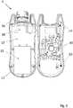
1 zeigt eine schematische perspektivische Vorderansicht einer Ausführungsform des erfindungsgemäßen Fernbedienungssystems;2 zeigt eine schematische perspektivische Rückansicht der Fernbedienung des erfindungsgemäßen Fernbedienungssystems gemäß der Ausführungsform von1 ;3 zeigt eine seitliche Schnittdarstellung mit einer Detailvergrößerung der Fernbedienung des erfindungsgemäßen Fernbedienungssystems gemäß der Ausführungsform von1 ;4 zeigt eine Detailansicht der Fernbedienung des erfindungsgemäßen Fernbedienungssystems gemäß der Ausführungsform von1 ;5 zeigt eine schematische Explosionsdarstellung der Fernbedienung des erfindungsgemäßen Fernbedienungssystems gemäß der Ausführungsform von1 ;6 zeigt eine schematische Darstellung der Fernbedienung des erfindungsgemäßen Fernbedienungssystems gemäß der Ausführungsform von1 im geöffneten Zustand;7 zeigt die Ladestation des Fernbedienungssystems gemäß der Ausführungsform von1 in einer schematischen Explosionsdarstellung;8 zeigt dieLadestation 6 desFernbedienungssystems 2 gemäß der Ausführungsform von1 in einer schematischen perspektivischen Vorderansicht; und9 zeigt die Ladestation des Fernbedienungssystems gemäß der Ausführungsform von1 in einer schematischen perspektivischen Rückansicht.10 zeigt schematisch eine bevorzugte Anordnung der Datenkommunikationsstrecken.
1 shows a schematic perspective front view of an embodiment of the remote control system according to the invention;2 shows a schematic perspective rear view of the remote control of the remote control system according to the invention according to the embodiment of FIG1 ;3 shows a side sectional view with an enlarged detail of the remote control of the remote control system according to the invention according to the embodiment of FIG1 ;4 shows a detailed view of the remote control of the remote control system according to the invention according to the embodiment of FIG1 ;5 shows a schematic exploded view of the remote control of the remote control system according to the invention according to the embodiment of FIG1 ;6 shows a schematic representation of the remote control of the remote control system according to the invention according to the embodiment of FIG1 in the open state;7 12 shows the charging station of the remote control system according to the embodiment of FIG1 in a schematic exploded view;8th 12 shows the chargingstation 6 of theremote control system 2 according to the embodiment of FIG1 in a schematic perspective front view; and9 12 shows the charging station of the remote control system according to the embodiment of FIG1 in a schematic perspective rear view.10 shows schematically a preferred arrangement of the data communication links.
Bevorzugte Ausführungsformen der Erfindung werden nachfolgend ausführlich unter Bezugnahme auf die begleitenden Zeichnungen beschrieben. In den Figuren werden für gleiche oder entsprechende Komponenten die gleichen Bezugszeichen verwendet, sofern nicht anders angegeben.Preferred embodiments of the invention are described in detail below with reference to the accompanying drawings. In the figures, the same reference numbers are used for the same or corresponding components, unless otherwise indicated.
Die vorstehenden Ausführungsbeispiele der vorliegenden Erfindung wurden anhand beispielhafter Figuren detailliert beschrieben. Die Merkmale der Ausführungsbeispiele sind im Ganzen oder teilweise kombinierbar und die vorliegende Erfindung ist nicht auf die beschriebenen Ausführungsbeispiele beschränkt.The above exemplary embodiments of the present invention have been described in detail using exemplary figures. The features of the embodiments can be combined in whole or in part and the present invention is not limited to the described embodiments.
BezugszeichenlisteReference List
- Ff
- Funkempfänger; M Maschineradio receiver; M machine
- 22
- Fernbedienungssystemremote control system
- 44
- Fernbedienungremote control
- 66
- Ladestationcharging station
- 77
- Muldetrough
- 88th
- Ausklinkungnotch
- 1010
- Pairing Symbolpairing icon
- 1212
- Gehäuseoberteilhousing top
- 1414
- Gehäuseunterteilhousing base
- 1616
- Labyrinthdichtunglabyrinth seal
- 1818
- erstes Lochfirst hole
- 2020
- Schraubescrew
- 2222
- zweites Lochsecond hole
- 2424
- Senkunglowering
- 2626
- TastaturKeyboard
- 2828
- DomDom
- 3030
- Platinecircuit board
- 3232
- Akkubattery pack
- 3434
- Clipclip
- 3636
- Not-Aus-SchalterEmergency switch
- 3838
- Anschlusskabelconnection cable
- 4040
- Ladestationoberteilcharging station top
- 4242
- Ladestationunterteilcharging station base
- 4444
- Schraubescrew
- 4646
- Ladestation-PairinganzeigeCharging station pairing indicator
- 4848
- Hauptplatinemotherboard
- 5050
- NFC-AntenneNFC antenna
- 5252
- Hohlsteckerbarrel connector
- 5454
- FußFoot
- 5656
- NaseNose
- 5858
- Haltelochholding hole
Claims (15)
Translated fromGermanPriority Applications (2)
| Application Number | Priority Date | Filing Date | Title |
|---|---|---|---|
| DE102020212976.2ADE102020212976A1 (en) | 2020-10-14 | 2020-10-14 | Wireless remote control system |
| EP21202581.1AEP3985634A1 (en) | 2020-10-14 | 2021-10-14 | Wireless remote control system |
Applications Claiming Priority (1)
| Application Number | Priority Date | Filing Date | Title |
|---|---|---|---|
| DE102020212976.2ADE102020212976A1 (en) | 2020-10-14 | 2020-10-14 | Wireless remote control system |
Publications (1)
| Publication Number | Publication Date |
|---|---|
| DE102020212976A1true DE102020212976A1 (en) | 2022-04-14 |
Family
ID=78211913
Family Applications (1)
| Application Number | Title | Priority Date | Filing Date |
|---|---|---|---|
| DE102020212976.2APendingDE102020212976A1 (en) | 2020-10-14 | 2020-10-14 | Wireless remote control system |
Country Status (2)
| Country | Link |
|---|---|
| EP (1) | EP3985634A1 (en) |
| DE (1) | DE102020212976A1 (en) |
Cited By (1)
| Publication number | Priority date | Publication date | Assignee | Title |
|---|---|---|---|---|
| DE202024104770U1 (en) | 2024-08-22 | 2024-09-17 | Maha Maschinenbau Haldenwang Gmbh & Co. Kg | Universal remote control for workshop devices |
Citations (5)
| Publication number | Priority date | Publication date | Assignee | Title |
|---|---|---|---|---|
| US20110098087A1 (en) | 2009-10-28 | 2011-04-28 | Google Inc. | Mobile Computing Device Dock |
| US20120053781A1 (en) | 2003-05-13 | 2012-03-01 | Spx Corporation | Cellular phone configured with off-board device capabilities and starter/charger and battery testing capabilities |
| US20130179061A1 (en) | 2010-06-10 | 2013-07-11 | The Regents Of The University Of California | Smart electric vehicle (ev) charging and grid integration apparatus and methods |
| DE102016217030A1 (en) | 2016-09-07 | 2018-03-08 | Maha Maschinenbau Haldenwang Gmbh & Co. Kg | Control device for a machine |
| US20200247264A1 (en) | 2019-02-01 | 2020-08-06 | Crown Equipment Corporation | On-board charging station for a remote control device |
Family Cites Families (2)
| Publication number | Priority date | Publication date | Assignee | Title |
|---|---|---|---|---|
| DE102010025346B4 (en)* | 2010-06-28 | 2012-03-08 | Db Schenker Rail Deutschland Ag | Apparatus and method for radio remote control of a mobile brake tester |
| DE202019003789U1 (en)* | 2019-09-16 | 2020-03-19 | Ntec Normalien Gmbh | Injection - die casting tool |
- 2020
- 2020-10-14DEDE102020212976.2Apatent/DE102020212976A1/enactivePending
- 2021
- 2021-10-14EPEP21202581.1Apatent/EP3985634A1/enactivePending
Patent Citations (5)
| Publication number | Priority date | Publication date | Assignee | Title |
|---|---|---|---|---|
| US20120053781A1 (en) | 2003-05-13 | 2012-03-01 | Spx Corporation | Cellular phone configured with off-board device capabilities and starter/charger and battery testing capabilities |
| US20110098087A1 (en) | 2009-10-28 | 2011-04-28 | Google Inc. | Mobile Computing Device Dock |
| US20130179061A1 (en) | 2010-06-10 | 2013-07-11 | The Regents Of The University Of California | Smart electric vehicle (ev) charging and grid integration apparatus and methods |
| DE102016217030A1 (en) | 2016-09-07 | 2018-03-08 | Maha Maschinenbau Haldenwang Gmbh & Co. Kg | Control device for a machine |
| US20200247264A1 (en) | 2019-02-01 | 2020-08-06 | Crown Equipment Corporation | On-board charging station for a remote control device |
Cited By (1)
| Publication number | Priority date | Publication date | Assignee | Title |
|---|---|---|---|---|
| DE202024104770U1 (en) | 2024-08-22 | 2024-09-17 | Maha Maschinenbau Haldenwang Gmbh & Co. Kg | Universal remote control for workshop devices |
Also Published As
| Publication number | Publication date |
|---|---|
| EP3985634A1 (en) | 2022-04-20 |
Similar Documents
| Publication | Publication Date | Title |
|---|---|---|
| EP3453559B1 (en) | Charging cable and adapter for electrically charging an energy storage device on an energy supply device | |
| DE10014949B4 (en) | Device on wheeled vehicles having pneumatic tires for use in a tire pressure monitoring system | |
| DE4310855A1 (en) | Device for monitoring at least one connection of a medical hose line system | |
| EP1135268A1 (en) | Arrangement for transmitting signals from a device monitoring tyre pressure on the wheels of a motor vehicle to an evaluation device arranged in a motor vehicle | |
| DE112017005187T5 (en) | Belt status monitoring system | |
| WO2007003381A1 (en) | Device for detecting and for indicating the position of components of vehicle couplings | |
| EP1696680B1 (en) | Arrangement to monitor the connection state of several connections | |
| EP3519254A1 (en) | Apparatus for determining the position of a mobile access device on the vehicle | |
| DE102020212976A1 (en) | Wireless remote control system | |
| DE102012113015A1 (en) | A device for emergency signaling in a vehicle crash and method of operation | |
| DE102008035243A1 (en) | Switchgear for a vehicle with an electronic immobilizer and method for actuating an electronic immobilizer | |
| DE102011001650A1 (en) | Device for supplying power to parking aids for vehicles with trailer coupling, has housing with thirteen-pins electrical plug that is inserted in socket of motor vehicle, where socket is provided for carrier or supporter | |
| EP4086400A1 (en) | Channel inspection and/or maintenance system | |
| DE102016109464B4 (en) | Optical assembly display for cable harnesses | |
| WO2019193166A1 (en) | Safety belt buckle, aeroplane safety belt, system for detecting a closed state of a safety belt, and method for detecting a closed state | |
| DE20320506U1 (en) | System with vehicle and coupled trailer, has wireless connection forming vehicle and trailer interfaces enabling data communications between vehicle and trailer using electromagnetic waves or ultrasound | |
| EP1772707A2 (en) | Measuring device | |
| EP1369838A1 (en) | Radio interface between vehicle and trailer | |
| EP0921607A2 (en) | Connector to transfer data between an electrical voltage source and data processing device | |
| WO2022008947A1 (en) | Device for remote controlling machines | |
| DE202020002867U1 (en) | Device for remote control of machines | |
| DE102018209841A1 (en) | Mobile end device for tire monitoring and system for tire monitoring | |
| EP3446553A1 (en) | Lighting device comprising the transmission of operating data | |
| DE102019200554A1 (en) | Vehicle tires | |
| DE102023104318A1 (en) | Communication device |
Legal Events
| Date | Code | Title | Description |
|---|---|---|---|
| R163 | Identified publications notified |