DE102020202935A1 - Coupling element for a closed fluid transfer system, mating coupling element for such a coupling element and coupling system - Google Patents
Coupling element for a closed fluid transfer system, mating coupling element for such a coupling element and coupling systemDownload PDFInfo
- Publication number
- DE102020202935A1 DE102020202935A1DE102020202935.0ADE102020202935ADE102020202935A1DE 102020202935 A1DE102020202935 A1DE 102020202935A1DE 102020202935 ADE102020202935 ADE 102020202935ADE 102020202935 A1DE102020202935 A1DE 102020202935A1
- Authority
- DE
- Germany
- Prior art keywords
- coupling
- coupling element
- housing
- sealing element
- longitudinal axis
- Prior art date
- Legal status (The legal status is an assumption and is not a legal conclusion. Google has not performed a legal analysis and makes no representation as to the accuracy of the status listed.)
- Pending
Links
Images


Classifications
- A—HUMAN NECESSITIES
- A61—MEDICAL OR VETERINARY SCIENCE; HYGIENE
- A61M—DEVICES FOR INTRODUCING MEDIA INTO, OR ONTO, THE BODY; DEVICES FOR TRANSDUCING BODY MEDIA OR FOR TAKING MEDIA FROM THE BODY; DEVICES FOR PRODUCING OR ENDING SLEEP OR STUPOR
- A61M5/00—Devices for bringing media into the body in a subcutaneous, intra-vascular or intramuscular way; Accessories therefor, e.g. filling or cleaning devices, arm-rests
- A61M5/14—Infusion devices, e.g. infusing by gravity; Blood infusion; Accessories therefor
- A61M5/1413—Modular systems comprising interconnecting elements
- A—HUMAN NECESSITIES
- A61—MEDICAL OR VETERINARY SCIENCE; HYGIENE
- A61M—DEVICES FOR INTRODUCING MEDIA INTO, OR ONTO, THE BODY; DEVICES FOR TRANSDUCING BODY MEDIA OR FOR TAKING MEDIA FROM THE BODY; DEVICES FOR PRODUCING OR ENDING SLEEP OR STUPOR
- A61M39/00—Tubes, tube connectors, tube couplings, valves, access sites or the like, specially adapted for medical use
- A61M39/10—Tube connectors; Tube couplings
- A61M39/16—Tube connectors; Tube couplings having provision for disinfection or sterilisation
- A61M39/165—Shrouds or protectors for aseptically enclosing the connector
- A—HUMAN NECESSITIES
- A61—MEDICAL OR VETERINARY SCIENCE; HYGIENE
- A61M—DEVICES FOR INTRODUCING MEDIA INTO, OR ONTO, THE BODY; DEVICES FOR TRANSDUCING BODY MEDIA OR FOR TAKING MEDIA FROM THE BODY; DEVICES FOR PRODUCING OR ENDING SLEEP OR STUPOR
- A61M39/00—Tubes, tube connectors, tube couplings, valves, access sites or the like, specially adapted for medical use
- A61M39/10—Tube connectors; Tube couplings
- A—HUMAN NECESSITIES
- A61—MEDICAL OR VETERINARY SCIENCE; HYGIENE
- A61M—DEVICES FOR INTRODUCING MEDIA INTO, OR ONTO, THE BODY; DEVICES FOR TRANSDUCING BODY MEDIA OR FOR TAKING MEDIA FROM THE BODY; DEVICES FOR PRODUCING OR ENDING SLEEP OR STUPOR
- A61M5/00—Devices for bringing media into the body in a subcutaneous, intra-vascular or intramuscular way; Accessories therefor, e.g. filling or cleaning devices, arm-rests
- A61M5/14—Infusion devices, e.g. infusing by gravity; Blood infusion; Accessories therefor
- A61M5/162—Needle sets, i.e. connections by puncture between reservoir and tube ; Connections between reservoir and tube
- F—MECHANICAL ENGINEERING; LIGHTING; HEATING; WEAPONS; BLASTING
- F16—ENGINEERING ELEMENTS AND UNITS; GENERAL MEASURES FOR PRODUCING AND MAINTAINING EFFECTIVE FUNCTIONING OF MACHINES OR INSTALLATIONS; THERMAL INSULATION IN GENERAL
- F16L—PIPES; JOINTS OR FITTINGS FOR PIPES; SUPPORTS FOR PIPES, CABLES OR PROTECTIVE TUBING; MEANS FOR THERMAL INSULATION IN GENERAL
- F16L37/00—Couplings of the quick-acting type
- F16L37/28—Couplings of the quick-acting type with fluid cut-off means
- F16L37/38—Couplings of the quick-acting type with fluid cut-off means with fluid cut-off means in only one of two pipe-end fittings
- F16L37/46—Couplings of the quick-acting type with fluid cut-off means with fluid cut-off means in only one of two pipe-end fittings with a gate valve or sliding valve
- A—HUMAN NECESSITIES
- A61—MEDICAL OR VETERINARY SCIENCE; HYGIENE
- A61M—DEVICES FOR INTRODUCING MEDIA INTO, OR ONTO, THE BODY; DEVICES FOR TRANSDUCING BODY MEDIA OR FOR TAKING MEDIA FROM THE BODY; DEVICES FOR PRODUCING OR ENDING SLEEP OR STUPOR
- A61M39/00—Tubes, tube connectors, tube couplings, valves, access sites or the like, specially adapted for medical use
- A61M39/10—Tube connectors; Tube couplings
- A61M2039/1027—Quick-acting type connectors
- A—HUMAN NECESSITIES
- A61—MEDICAL OR VETERINARY SCIENCE; HYGIENE
- A61M—DEVICES FOR INTRODUCING MEDIA INTO, OR ONTO, THE BODY; DEVICES FOR TRANSDUCING BODY MEDIA OR FOR TAKING MEDIA FROM THE BODY; DEVICES FOR PRODUCING OR ENDING SLEEP OR STUPOR
- A61M39/00—Tubes, tube connectors, tube couplings, valves, access sites or the like, specially adapted for medical use
- A61M39/10—Tube connectors; Tube couplings
- A61M2039/1061—Break-apart tubing connectors or couplings
- A—HUMAN NECESSITIES
- A61—MEDICAL OR VETERINARY SCIENCE; HYGIENE
- A61M—DEVICES FOR INTRODUCING MEDIA INTO, OR ONTO, THE BODY; DEVICES FOR TRANSDUCING BODY MEDIA OR FOR TAKING MEDIA FROM THE BODY; DEVICES FOR PRODUCING OR ENDING SLEEP OR STUPOR
- A61M39/00—Tubes, tube connectors, tube couplings, valves, access sites or the like, specially adapted for medical use
- A61M39/10—Tube connectors; Tube couplings
- A61M2039/1072—Tube connectors; Tube couplings with a septum present in the connector
- A—HUMAN NECESSITIES
- A61—MEDICAL OR VETERINARY SCIENCE; HYGIENE
- A61M—DEVICES FOR INTRODUCING MEDIA INTO, OR ONTO, THE BODY; DEVICES FOR TRANSDUCING BODY MEDIA OR FOR TAKING MEDIA FROM THE BODY; DEVICES FOR PRODUCING OR ENDING SLEEP OR STUPOR
- A61M39/00—Tubes, tube connectors, tube couplings, valves, access sites or the like, specially adapted for medical use
- A61M39/22—Valves or arrangement of valves
- A61M39/26—Valves closing automatically on disconnecting the line and opening on reconnection thereof
- A61M2039/262—Valves closing automatically on disconnecting the line and opening on reconnection thereof having a fluid space within the valve remaining the same upon connection and disconnection, i.e. neutral-drawback valve
- A—HUMAN NECESSITIES
- A61—MEDICAL OR VETERINARY SCIENCE; HYGIENE
- A61M—DEVICES FOR INTRODUCING MEDIA INTO, OR ONTO, THE BODY; DEVICES FOR TRANSDUCING BODY MEDIA OR FOR TAKING MEDIA FROM THE BODY; DEVICES FOR PRODUCING OR ENDING SLEEP OR STUPOR
- A61M39/00—Tubes, tube connectors, tube couplings, valves, access sites or the like, specially adapted for medical use
- A61M39/22—Valves or arrangement of valves
- A61M39/26—Valves closing automatically on disconnecting the line and opening on reconnection thereof
- A61M2039/267—Valves closing automatically on disconnecting the line and opening on reconnection thereof having a sealing sleeve around a tubular or solid stem portion of the connector
- F—MECHANICAL ENGINEERING; LIGHTING; HEATING; WEAPONS; BLASTING
- F16—ENGINEERING ELEMENTS AND UNITS; GENERAL MEASURES FOR PRODUCING AND MAINTAINING EFFECTIVE FUNCTIONING OF MACHINES OR INSTALLATIONS; THERMAL INSULATION IN GENERAL
- F16L—PIPES; JOINTS OR FITTINGS FOR PIPES; SUPPORTS FOR PIPES, CABLES OR PROTECTIVE TUBING; MEANS FOR THERMAL INSULATION IN GENERAL
- F16L2201/00—Special arrangements for pipe couplings
- F16L2201/40—Special arrangements for pipe couplings for special environments
- F16L2201/44—Special arrangements for pipe couplings for special environments sterile
Landscapes
- Health & Medical Sciences (AREA)
- Engineering & Computer Science (AREA)
- Heart & Thoracic Surgery (AREA)
- Life Sciences & Earth Sciences (AREA)
- General Health & Medical Sciences (AREA)
- Anesthesiology (AREA)
- Biomedical Technology (AREA)
- Hematology (AREA)
- Veterinary Medicine (AREA)
- Animal Behavior & Ethology (AREA)
- Public Health (AREA)
- General Engineering & Computer Science (AREA)
- Vascular Medicine (AREA)
- Pulmonology (AREA)
- Mechanical Engineering (AREA)
- Epidemiology (AREA)
- Quick-Acting Or Multi-Walled Pipe Joints (AREA)
Abstract
Translated fromGermanDescription
Translated fromGermanDie Erfindung betrifft ein Kupplungselement für ein geschlossenes Fluidtransfersystem, ein Gegenkupplungselement für ein solches Kupplungselement sowie ein Kupplungssystem.The invention relates to a coupling element for a closed fluid transfer system, a mating coupling element for such a coupling element and a coupling system.
Viele Substanzen, die als Injektionen oder in vergleichbarer Zuführungsform verabreicht werden, wie CMR-Arzneimittel, die beispielsweise in der Krebstherapie eingesetzt werden und bei ihrer therapeutischen Anwendung vor allem auf die Schädigung wachstumsintensiver Tumorzellen gerichtet sind, weisen außerhalb der eigentlichen Therapieanwendung ein erhebliches Gefährdungspotential auf. So sind solche Substanzen bedingt durch ihren Wirkmechanismus zum Teil selbst krebserzeugend, weshalb der Kontakt mit nicht in Therapie befindlichen Personen zu vermeiden ist. Für CMR-Arzneimittel werden daher bei der Herstellung applikationsfertiger Zubereitungen vermehrt geschlossene Medikamententransfersystem, sogenannte „Closed System Transfer Devices“ oder auch CSTDs eingesetzt. Wichtiger Bestandteil solcher CSTDs sind Kupplungssysteme, die den sicheren Transfer von CMR-Arzneimitteln oder anderen Substanzen ermöglichen und nach dem Trennen der Verbindung trocken abschließen, um so die Umgebung vor einer Kontamination, z.B. durch Leckagen oder Tropfenbildung auf den Oberflächen der Kupplungselemente, zu schützen.Many substances that are administered as injections or in a comparable delivery form, such as CMR drugs, which are used, for example, in cancer therapy and whose therapeutic application is primarily aimed at damaging growth-intensive tumor cells, have a significant potential risk outside of the actual therapeutic application. Due to their mechanism of action, such substances are in part self-carcinogenic, which is why contact with people who are not in therapy should be avoided. For CMR drugs, therefore, closed drug transfer systems, so-called "closed system transfer devices" or CSTDs, are increasingly being used in the manufacture of ready-to-use preparations. An important component of such CSTDs are coupling systems that enable the safe transfer of CMR drugs or other substances and after disconnecting the connection, lock them dry in order to protect the environment from contamination, e.g. through leaks or the formation of drops on the surfaces of the coupling elements.
Kupplungssystem dieser Art werden im Allgemeinen mit den Begriffen „dry connection“, „automatic self-sealing technology“ oder „closed connection“ in Verbindung gebracht und essentiell für die Realisierung geschlossener F lu idtransfersysteme.Coupling systems of this type are generally associated with the terms “dry connection”, “automatic self-sealing technology” or “closed connection” and are essential for the implementation of closed fluid transfer systems.
Bekannte Kupplungssysteme sind in ihrer Handhabung und Verbindungsstruktur häufig komplex und können schlechte Durchflussraten aufweisen. Zudem können Fluidrückstände an den Dichtflächen bzw. Kupplungsflächen auftreten, wenn keine konstante Flächenpressung der Dichtflächen aufrechterhalten wird.Known coupling systems are often complex in their handling and connection structure and can have poor flow rates. In addition, fluid residues can occur on the sealing surfaces or coupling surfaces if a constant surface pressure of the sealing surfaces is not maintained.
Allen derzeitigen Systemen ist darüber hinaus gemein, dass sie vergleichsweise groß sind, was zu Nachteilen bei einer Anwendung in Patientennähe führt, und zumindest ein Kupplungselement oder eine Gegenkupplungselement strukturbedingt eine schlechte Zugänglichkeit der Kupplungs- bzw. Gegenkupplungsfläche aufweist, so dass eine Desinfektion erschwert wird.All current systems also have in common that they are comparatively large, which leads to disadvantages when used in the vicinity of the patient, and at least one coupling element or one counter-coupling element has poor accessibility of the coupling or counter-coupling surface due to the structure, so that disinfection is difficult.
In Anbetracht der mit dem Stand der Technik verbundenen Nachteile ist es Aufgabe der vorliegenden Erfindung, ein Kupplungselement, ein Gegenkupplungselement sowie ein Kupplungssystem für ein geschlossenes Fluidtransfersystem bereitzustellen, bei dem die jeweiligen Kupplungsflächen im dekonnektierten Zustand trocken abschließen und in einfacher Weise sicher handhabbar sind.In view of the disadvantages associated with the prior art, the object of the present invention is to provide a coupling element, a mating coupling element and a coupling system for a closed fluid transfer system in which the respective coupling surfaces close dry in the disconnected state and can be easily and safely handled.
Die erfindungsgemäße Aufgabe wird durch ein Kupplungselement für ein geschlossenes Fluidtransfersystem nach Anspruch 1, ein Gegenkupplungselement nach Anspruch 13 sowie ein Kupplungssystem nach Anspruch 15 gelöst. Weitere vorteilhafte Ausgestaltungen der Erfindung ergeben sich aus den Unteransprüchen.The object according to the invention is achieved by a coupling element for a closed fluid transfer system according to claim 1, a mating coupling element according to
Erfindungsgemäß umfasst das Kupplungselement für ein geschlossenes Fluidtransfersystem ein Kupplungselementgehäuse mit einem Fluidanschluss und einer Kupplungsseite, wobei das Kupplungselementgehäuse eine sich von dem Fluidanschluss in Richtung der Kupplungsseite erstreckende Längsachse aufweist, einen Dorn mit zumindest einer Fluidöffnung, der in einer am Fluidanschluss angeordneten Dornaufnahme des Gehäuses gehalten wird und sich in Richtung der Längsachse in das Kupplungselementgehäuse hinein erstreckt, wobei die zumindest eine Fluidöffnung in einem der Kupplungsseite zugewandten Endabschnitt des Dorns angeordnet ist, eine in dem Kupplungselementgehäuse auf der Kupplungsseite angeordnete Dichtelementaufnahme und ein Dichtelement, das in der Dichtelementaufnahme angeordnet ist, wobei das Kupplungsgehäuse einen Gehäuseabschnitt aufweist, der die Dichtelementaufnahme in Bezug auf die Längsachse in axialer Richtung zumindest abschnittsweise umgibt und auf der dem Dichtelement zugewandten Innenseite einen Kupplungsgehäusegewindeabschnitt aufweist, und wobei die Dichtelementaufnahme mit dem Dichtelement in Richtung der Längsachse über den Kupplungsgehäusegewindeabschnitt zwischen einer Position mit maximalem Abstand zum Fluidanschluss und einer Position mit minimalem Abstand zum Fluidanschluss über eine Dichtelementaufnahmeführungsstruktur geführt bewegbar ist.According to the invention, the coupling element for a closed fluid transfer system comprises a coupling element housing with a fluid connection and a coupling side, the coupling element housing having a longitudinal axis extending from the fluid connection in the direction of the coupling side, a mandrel with at least one fluid opening which is held in a mandrel receptacle of the housing arranged on the fluid connection and extends in the direction of the longitudinal axis into the coupling element housing, the at least one fluid opening being arranged in an end section of the mandrel facing the coupling side, a sealing element receptacle arranged in the coupling element housing on the coupling side and a sealing element arranged in the sealing element receptacle, wherein the coupling housing has a housing section which surrounds the sealing element receptacle at least in sections with respect to the longitudinal axis in the axial direction and on the one facing the sealing element n inside has a coupling housing thread section, and wherein the sealing element receptacle with the sealing element can be moved in the direction of the longitudinal axis via the coupling housing thread section between a position with a maximum distance from the fluid connection and a position with a minimum distance from the fluid connection via a sealing element receiving guide structure.
Durch das Zusammenwirken der Dichtelementaufnahmeführungsstruktur mit dem Kupplungsgehäusegewindeabschnitt kann die Dichtelementaufnahme gegen eine unbeabsichtigte Bewegung durch reine Druck- oder Zugkräfte gesichert werden. Die Position mit maximalem Abstand zum Fluidanschluss korrespondiert zu einer Position der Dichtelementaufnahme in einem dekonnektierten Zustand, während die Position mit minimalem Abstand zum Fluidanschluss bevorzugt dann vorliegt, wenn ein konnektierter Zustand erreicht wird, der für eine fluide Verbindung mit einem Gegenkupplungselement vorgesehen ist.Due to the interaction of the sealing element receiving guide structure with the coupling housing thread section, the sealing element receiving can be secured against unintentional movement by pure compressive or tensile forces. The position with the maximum distance from the fluid connection corresponds to a position of the sealing element receptacle in a disconnected state, while the position with the minimum distance from the fluid connection is preferably present when a connected state is reached which is provided for a fluid connection with a mating coupling element.
Der Begriff „Gewinde“ in Bezug auf den Kupplungsgehäusegewindeabschnitt oder auch im Folgenden ist nicht auf ein isometrisches Gewinde oder ein Gewinde mit schrägen Gewindeflanken beschränkt, sondern umfasst allgemein eine Strukturausbildung, bei der eine Führungsstruktur wendelartig ausgebildet wird.The term “thread” in relation to the coupling housing thread section or also in the following does not refer to an isometric thread or a thread with angled thread flanks limited, but generally includes a structure formation in which a guide structure is formed helically.
Insbesondere ist die zumindest eine Fluidöffnung im Dichtelement angeordnet ist, wenn sich die Dichtelementaufnahme mit dem Dichtelement in der Position mit maximalem Abstand zum Fluidanschluss befindet.In particular, the at least one fluid opening is arranged in the sealing element when the sealing element receptacle with the sealing element is in the position at the maximum distance from the fluid connection.
Demnach kann hinsichtlich der vorstehenden Reduzierung des Risikos einer unbeabsichtigten Bewegung das Austreten eines Fluids in einem dekonnektierten Zustand verhindert werden.Accordingly, with regard to the above reduction in the risk of unintentional movement, the escape of a fluid in a disconnected state can be prevented.
In einer Ausgestaltung ist der Kupplungsgehäusegewindeabschnitt als Innengewinde ausgebildet und die Dichtelementaufnahmeführungsstruktur weist zumindest einen in das Innengewinde eingreifbaren in Bezug auf die Längsachse radial nach außen weisenden Vorsprung auf.In one embodiment, the coupling housing thread section is designed as an internal thread and the sealing element receiving guide structure has at least one projection that can be engaged in the internal thread and that points radially outward with respect to the longitudinal axis.
Die Dichtelementaufnahmeführungsstruktur kann somit in einfacher Weise ausgebildet werden. Grundsätzlich ist es aber auch möglich, den Kupplungsgehäusegewindeabschnitt als Außengewinde auszubilden, wobei die Dichtelementaufnahmeführungsstruktur zumindest abschnittsweise als hierzu korrespondierendes Innengewinde ausgestaltet ist.The sealing element receiving guide structure can thus be formed in a simple manner. In principle, however, it is also possible to design the coupling housing thread section as an external thread, the sealing element receiving guide structure being designed at least in sections as an internal thread corresponding thereto.
Insbesondere weist der Kupplungsgehäusegewindeabschnitt zumindest zwei voneinander getrennte, insbesondere zumindest zwei einander gegenüberliegende Gewindegänge aufweist.In particular, the coupling housing thread section has at least two mutually separate, in particular at least two mutually opposite thread turns.
In Verbindung mit zumindest zwei entsprechend einander gegenüberliegenden Dichtelementaufnahmeführungsstrukturen kann die Dichtelementaufnahme im Kupplungsgehäusegewindeabschnitt positionsstabiler geführt werden, da hierdurch ein Verkippen der Dichtelementaufnahme verhindert wird. Die Anzahl der Gewindegänge kann jedoch auch geringer sein als die Anzahl der Dichtelementaufnahmeführungsstrukturen, um beispielsweise die Dichtelementaufnahme in unterschiedlichen Orientierung in das Kupplungsgehäuse einzusetzen und/oder unterschiedliche Bewegungen der Dichtelementaufnahme durch unterschiedliche Gewindegänge vorzusehen.In connection with at least two correspondingly opposite sealing element receiving guide structures, the sealing element receiving in the coupling housing thread section can be guided in a more stable position, since this prevents the sealing element receiving from tilting. The number of threads can, however, also be less than the number of sealing element receiving guide structures, for example to insert the sealing element receiving in different orientations in the coupling housing and / or to provide different movements of the sealing element receiving through different threads.
In einer Ausgestaltung erstreckt sich zumindest ein Gewindegang des Kupplungsgehäusegewindeabschnitts in Bezug auf die Längsachse über einen Winkel kleiner 360°, insbesondere über einen Winkel von im Wesentlichen 180°.In one embodiment, at least one thread turn of the coupling housing thread section extends over an angle of less than 360 °, in particular over an angle of substantially 180 °, with respect to the longitudinal axis.
Die geführte Bewegung der Dichtelementaufnahme kann somit über einen begrenzten Drehwinkel erfolgen, was die Handhabung vereinfacht. Zudem erleichtert ein verkürzter Drehwinkel, also ein Drehwinkel zur Erreichung einer Zielposition, der nicht mehrere Umdrehungen umfasst, die Kontrolle der Bewegung, da nicht mehrere Umdrehungen nachverfolgt werden müssen. In diesem Zusammenhang können optische oder haptische Markierungselemente die Bewegungskontrolle unterstützen.The guided movement of the sealing element receptacle can thus take place over a limited angle of rotation, which simplifies handling. In addition, a shortened angle of rotation, that is to say an angle of rotation to reach a target position that does not include several revolutions, facilitates the control of the movement, since several revolutions do not have to be tracked. In this context, optical or haptic marking elements can support movement control.
In einer Weiterbildung weist zumindest ein Gewindegang des Kupplungsgehäusegewindeabschnitt an seinem dem Fluidanschluss zugewandten Ende einen zur Längsachse orthogonalen Abschnitt aufweist.In a further development, at least one thread turn of the coupling housing thread section has a section orthogonal to the longitudinal axis at its end facing the fluid connection.
Die Steigung des Gewindegangs wird somit über diesen Abschnitt nicht fortgesetzt. Wenn die Dichtelementaufnahmeführungsstruktur in den orthogonalen Abschnitt bewegt wird, kann die Dichtelementaufnahme nicht durch Aufbringung reiner Zug- oder Druckkräfte in Richtung der Längsachse aus dieser Position bewegt werden. Entsprechend ermöglicht der orthogonale Abschnitt eine Sicherung der Positionierung der Dichtelementaufnahme in dieser Position, insbesondere in der Position mit minimalem Abstand zum Fluidanschluss, wenn der orthogonale Abschnitt zu dieser Position korrespondiert.The pitch of the thread is therefore not continued over this section. When the sealing element receiving guide structure is moved into the orthogonal section, the sealing element receiving cannot be moved from this position by applying pure tensile or compressive forces in the direction of the longitudinal axis. Correspondingly, the orthogonal section enables the positioning of the sealing element receptacle to be secured in this position, in particular in the position with a minimal distance from the fluid connection when the orthogonal section corresponds to this position.
Insbesondere weist zumindest ein Gewindegang des Kupplungsgehäusegewindeabschnitts an seinem dem Fluidanschluss zugewandten Ende einen in Richtung der Längsachse rückversetzten Abschnitt auf, der gegenüber dem Gewindegang in Richtung der Kupplungsseite rückversetzt ist.In particular, at least one thread turn of the coupling housing thread section has, at its end facing the fluid connection, a section set back in the direction of the longitudinal axis, which is set back with respect to the thread turn in the direction of the coupling side.
Wenn die Dichtelementaufnahmeführungsstruktur in den rückversetzen Abschnitt bewegt wird, kann die Dichtelementaufnahme nicht durch Aufbringung reiner Drehbewegungen um die Längsachse aus dieser Position bewegt werden, sondern muss beispielweise zunächst durch Aufbringung einer Druckkraft auf die Dichtelementaufnahme entlang der Längsachse in Richtung des Fluidanschlusses aus dem rückversetzten Abschnitt bewegt werden. Die Positionierung der Dichtelementaufnahmeführungsstruktur im rückversetzten Abschnitt entspricht bevorzugt einer Position der Dichtelementaufnahme im konnektierten Zustand. Der rückversetzte Abschnitt kann alternativ oder ergänzend zum orthogonalen Abschnitt vorgesehen werden. Bei einer Kombination des rückversetzen und orthogonalen Abschnitts schließt sich der rückversetzte Abschnitt bevorzugt in Führungsrichtung der Dichtelementaufnahmeführungsstruktur an einem dem Fluidanschluss zugewandten Ende des Gewindegangs an den orthogonalen Abschnitt an. Beispielsweise wird die Dichtelementaufnahmeführungsstruktur zunächst entlang des zumindest einen eine Steigung aufweisenden Gewindegangs in Richtung des Fluidanschlusses bewegt, erreicht dann den orthogonalen Abschnitt und kann dann durch eine fortgesetzte Drehbewegung in den rückversetzten Abschnitt bewegt werden.When the sealing element receiving guide structure is moved into the recessed section, the sealing element receiving cannot be moved from this position by applying pure rotary movements around the longitudinal axis, but must first be moved out of the recessed section by applying a compressive force to the sealing element receiving along the longitudinal axis in the direction of the fluid connection will. The positioning of the sealing element receiving guide structure in the recessed section preferably corresponds to a position of the sealing element receiving in the connected state. The recessed section can be provided as an alternative or in addition to the orthogonal section. In the case of a combination of the recessed and orthogonal section, the recessed section preferably adjoins the orthogonal section in the guiding direction of the sealing element receiving guide structure at an end of the thread facing the fluid connection. For example, the sealing element receiving guide structure is first moved along the at least one thread turn having a pitch in the direction of the fluid connection, then reaches the orthogonal section and can then through a continued rotary motion to be moved into the recessed section.
In einer Ausgestaltung ist der Gehäuseabschnitt relativ zur Längsachse drehbar.In one embodiment, the housing section can be rotated relative to the longitudinal axis.
Die Dichtelementaufnahme kann somit über eine Drehbewegung des Gehäuseabschnitts um die Längsachse über die Dichtelementaufnahmeführungsstruktur entlang der Längsachse bewegt werden. Bevorzugt ist der Gehäuseabschnitt dabei ein gegenüber dem übrigen Gehäuse drehbar gelagerter Abschnitt, so dass die durch den Gehäuseabschnitt ausgeführte Drehbewegung nicht auf das übrige Gehäuse übertragen wird. Dies erleichtert die Handhabung bzw. Konnektierung und Dekonnektierung insbesondere, wenn beispielsweise weitere Komponenten bereits an den Fluidanschluss angeschlossen sind.The sealing element receptacle can thus be moved along the longitudinal axis via the sealing element receptacle guide structure by means of a rotary movement of the housing section about the longitudinal axis. The housing section is preferably a section that is rotatably mounted with respect to the rest of the housing, so that the rotary movement carried out by the housing section is not transmitted to the rest of the housing. This facilitates handling or connection and disconnection, in particular if, for example, further components are already connected to the fluid connection.
Alternativ oder ergänzend ist die Dichtelementaufnahme relativ zur Längsachse und/oder zum Kupplungselementgehäuse drehbar.Alternatively or in addition, the sealing element receptacle can be rotated relative to the longitudinal axis and / or to the coupling element housing.
Demnach wird nicht oder nicht nur der Gehäuseabschnitt zur Bewegung der Dichtelementaufnahme über die Dichtelementaufnahmeführungsstruktur im Eingriff mit zumindest einem entsprechenden Gewindegang gedreht, sondern die Dichtelementaufnahme.Accordingly, not, or not only, the housing section for moving the sealing element receptacle via the sealing element receptacle guide structure in engagement with at least one corresponding thread turn, but rather the sealing element receptacle.
Gemäß einer Weiterbildung bildet die Dichtelementaufnahme zusammen mit dem Dichtelement zumindest einen Teil einer kupplungsseitigen Stirnfläche des Kupplungselements aus.According to a development, the sealing element receptacle together with the sealing element forms at least part of a coupling-side end face of the coupling element.
Die Dichtelementaufnahme und das Dichtelement sind somit nicht rückversetzt, so dass sie eine gute Zugänglichkeit aufweisen, wodurch eine Desinfektion erleichtert wird. Die kupplungsseitige Stirnfläche kann insbesondere im Wesentlichen plan ausgeführt werden. Der Begriff „im Wesentlichen plan“ ist darauf gerichtet, dass kleinere Konturabweichungen, wie beispielsweise eine mittige Überhöhung durch das Dichtelement, ausgebildet sein können, diese aber keinen Einfluss auf die kupplungsseitige Stirnfläche des Kupplungselements im Sinne einer Zugänglichkeit haben.The sealing element receptacle and the sealing element are therefore not set back, so that they have good accessibility, as a result of which disinfection is facilitated. The coupling-side end face can in particular be designed to be essentially planar. The term “essentially flat” is aimed at ensuring that smaller contour deviations, such as a central elevation through the sealing element, can be formed, but that these have no influence on the coupling-side face of the coupling element in terms of accessibility.
Insbesondere weist die Dichtelementaufnahme an ihrem der Kupplungsseite zugewandten Ende eine kupplungselementseitige Befestigungsstruktur für ein Gegenkupplungselement, insbesondere zumindest zwei in Richtung der Längsachse in Richtung der Kupplungsseite vorstehende Schnapphaken, auf.In particular, at its end facing the coupling side, the sealing element receptacle has a coupling element-side fastening structure for a mating coupling element, in particular at least two snap hooks protruding in the direction of the longitudinal axis in the direction of the coupling side.
Durch die kupplungselementseitige Befestigungsstruktur an der Dichtelementaufnahme kann sichergestellt werden, dass ein hieran befestigtes Gegenkupplungselement über die Bewegung der Dichtelementaufnahme von einer Position mit maximalem Abstand zum Fluidanschluss und minimalen Abstand zum Fluidanschluss entlang der Längsachse in einer vorbestimmten Positionsbeziehung gehalten wird. Insbesondere weist eine solche vorbestimmte Positionsbeziehung eine konstante Flächenpressung zwischen dem Dichtelement und dem Gegenkupplungselementdichtelement auf, so dass eine Fluiddichtheit sichergestellt werden kann. Bevorzugt ist die Befestigungsstruktur so ausgelegt, dass die Befestigung des Gegenkupplungselements an der Befestigungsstruktur lediglich über die Aufbringung von Druckkräften in Richtung des Kupplungselements und/oder Gegenkupplungselement erfolgt und keine Drehbewegung ausgeführt wird, um die Dichtelementaufnahme nicht bereits während des Befestigungsvorgangs entlang des Gewindegangs zu bewegen. Sofern der Befestigungsvorgang eine Drehbewegung umfasst, sollte diese zumindest der Drehbewegung zur Bewegung der Dichtelementaufnahme entlang des Gewindegangs entgegengesetzt sein.The coupling element-side fastening structure on the sealing element receptacle can ensure that a mating coupling element fastened to it is held in a predetermined positional relationship by moving the sealing element receptacle from a position with a maximum distance from the fluid connection and a minimum distance from the fluid connection along the longitudinal axis. In particular, such a predetermined positional relationship has a constant surface pressure between the sealing element and the mating coupling element sealing element, so that fluid-tightness can be ensured. The fastening structure is preferably designed in such a way that the fastening of the counter-coupling element to the fastening structure takes place only by applying compressive forces in the direction of the coupling element and / or counter-coupling element and no rotary movement is performed in order not to move the sealing element receptacle along the thread during the fastening process. If the fastening process includes a rotary movement, this should be at least opposite to the rotary movement for moving the sealing element receptacle along the thread.
Die Verwendung von Schnapphaken als Befestigungsstruktur setzt beispielsweise eine Befestigung über eine Druckkraft in einfacher Weise um. Zudem stören Schnapphaken die Zugänglichkeit zur kupplungsseitigen Stirnfläche des Kupplungselements kaum, so dass eine Desinfektion weiterhin leicht möglich ist. Darüber hinaus kann ein Verkippen des Gegenkupplungselements durch zumindest zwei Schnapphaken, die bevorzugt einander gegenüberliegend angeordnet sind, verhindert werden.The use of snap hooks as a fastening structure, for example, implements fastening by means of a compressive force in a simple manner. In addition, snap hooks hardly interfere with the accessibility to the coupling-side end face of the coupling element, so that disinfection is still easily possible. In addition, tilting of the mating coupling element can be prevented by at least two snap hooks, which are preferably arranged opposite one another.
Gemäß einer Weiterbildung ist die Dichtelementaufnahme über ein elastisches Element, insbesondere ein Druckfederelement, das in Richtung der Längsachse wirkt und zwischen dem Fluidanschluss und der Dichtelementaufnahme angeordnet ist, im Kupplungselementgehäuse gelagert.According to a development, the sealing element receptacle is mounted in the coupling element housing via an elastic element, in particular a compression spring element, which acts in the direction of the longitudinal axis and is arranged between the fluid connection and the sealing element receptacle.
Das elastische Element kann über ein separates Federelement oder durch das Dichtelement oder die Dichtelementaufnahme gebildet werden. Sofern das elastische Element durch das Dichtelement oder die Dichtelementaufnahme gebildet wird, ist dieses Element in die entsprechenden Komponenten integriert oder wird durch diese, beispielsweise durch entsprechende Materialauswahl und/oder Strukturausbildung, ausgebildet. Das Dichtelement oder die Dichtelementaufnahme stützt sich in diesem Fall, ebenso wie ein separates Federelement in Längsrichtung gegen das Kupplungselementgehäuse ab. Die Dichtelementaufnahme wird über das elastische Element ohne äußere Krafteinwirkung in einer Position mit maximalem Abstand zum Fluidanschluss gehalten. Entsprechend erfordert eine Bewegung der Dichtelementaufnahme in Richtung des Fluidanschlusses eine Überwindung der Haltekraft, so dass das Risiko einer unbeabsichtigten Bewegung vermindert wird. Zudem unterstützt das elastische Element eine Rückbewegung von einem konnektierten Zustand in einen dekonnektierten Zustand.The elastic element can be formed by a separate spring element or by the sealing element or the sealing element receptacle. If the elastic element is formed by the sealing element or the sealing element receptacle, this element is integrated into the corresponding components or is formed by them, for example by appropriate material selection and / or structural design. In this case, the sealing element or the sealing element receptacle, like a separate spring element, is supported in the longitudinal direction against the coupling element housing. The sealing element receptacle is held by the elastic element in a position with the maximum distance from the fluid connection without the action of external force. Correspondingly, a movement of the sealing element receptacle in the direction of the fluid connection requires the holding force to be overcome, so that the risk of unintentional movement is decreased. In addition, the elastic element supports a return movement from a connected state to a disconnected state.
In einem weiteren Aspekt ist die Erfindung auf ein Gegenkupplungselement zur Kupplung mit einem vorstehend beschriebenen Kupplungselement gerichtet. Das Gegenkupplungselement umfasst ein Gegenkupplungselementgehäuse mit einem Gegenkupplungselementfluidanschluss und einer Gegenkupplungsseite, wobei das Gegenkupplungselementgehäuse eine sich von dem Gegenkupplungselementfluidanschluss in Richtung der Gegenkupplungsseite erstreckende Gegenkupplungselementlängsachse aufweist, sowie ein Gegenkupplungselementdichtelement, das in dem Gegenkupplungselementgehäuse angeordnet ist und zusammen mit dem Gegenkupplungselementgehäuse zumindest einen Teil einer gegenkupplungsseitigen Stirnfläche des Gegenkupplungselements ausbildet, wobei das Gegenkupplungselementgehäuse einen Befestigungsabschnitt aufweist, der sich von der Gegenkupplungsseite in Richtung der Gegenkupplungselementlängsachse in Richtung des Gegenkupplungselementfluidanschlusses erstreckt und eine gegenkupplungselementseitige Befestigungsstruktur, insbesondere eine Aussparung, zur Verbindung mit der kupplungselementseitigen Befestigungsstruktur, insbesondere zur Aufnahme der Schnapphaken, umfasst.In a further aspect, the invention is directed to a mating coupling element for coupling with a coupling element described above. The mating coupling element comprises a mating coupling element housing with a mating coupling element fluid connection and a mating coupling side, wherein the mating coupling element housing has a mating coupling element longitudinal axis extending from the mating coupling element fluid connection in the direction of the mating coupling side, as well as a mating coupling element longitudinal axis of a mating coupling element and a mating coupling element housing surface of the at least one mating coupling element housing surface, which is arranged together with the mating coupling element housing surface in the end face Forms mating coupling element, the mating coupling element housing having a fastening portion which extends from the mating coupling side in the direction of the mating coupling element longitudinal axis in the direction of the mating coupling element fluid connection and a mating coupling element-side fastening structure, in particular a recess, for connection to the coupling element-side fastening structure, in particular for receiving the snap-on element phakic, includes.
Die gegenkupplungselementseitige Befestigungsstruktur in somit von der Gegenkupplungsseite aus gesehen gegenüber der gegenkupplungsseitigen Stirnfläche rückversetzt, wodurch die gegenkupplungsseitige Stirnfläche des Gegenkupplungselementdichtelements mit vorbestimmter Flächenpressung bei Befestigung des Gegenkupplungselements mit dem Kupplungselement gehalten werden kann. Gleichzeitig wird die Zugänglichkeit der gegenkupplungsseitigen Stirnfläche, beispielsweise zu Desinfektionszwecken, hierdurch nicht beschränkt.The counter-coupling element-side fastening structure is therefore set back from the counter-coupling-side end face, as seen from the counter-coupling side, whereby the counter-coupling-side end face of the counter-coupling element sealing element can be held with a predetermined surface pressure when the counter-coupling element is fastened to the coupling element. At the same time, the accessibility of the counter-coupling-side end face, for example for disinfection purposes, is not restricted as a result.
Die gegenkupplungsseitige Befestigungsstruktur kann in Bezug auf die Gegenkupplungselementlängsachse radial umlaufend durchgängig sein, um eine Befestigung des Gegenkupplungselements mit dem Kupplungselement in beliebigen radialen Relativposition zu ermöglichen. Alternativ kann die gegenkupplungselementseitige Befestigungsstruktur nur abschnittsweise ausgebildet sein, um eine entsprechende Befestigung nur in einer oder mehreren vorbestimmten Relativpositionen zu erlauben. Beispielsweise kann bei nur einer zur Befestigung vorgesehenen Relativposition die gegenkupplungselementseitige Befestigungsstruktur Aussparungen aufweisen, die in ihrer Position und Dimensionierung in eineindeutiger Weise zu den Schnapphaken eines Kupplungselements korrespondieren.The counter-coupling-side fastening structure can be continuous radially circumferentially with respect to the counter-coupling element longitudinal axis in order to enable the counter-coupling element to be fastened to the coupling element in any radial relative position. Alternatively, the fastening structure on the counter-coupling element side can only be configured in sections in order to allow a corresponding fastening only in one or more predetermined relative positions. For example, in the case of only one relative position provided for fastening, the fastening structure on the counter-coupling element side can have recesses which correspond in their position and dimensions in a one-to-one manner to the snap hooks of a coupling element.
In einer Ausgestaltung weist das Gegenkupplungselementgehäuse an einer sich in Richtung der Gegenkupplungselementlängsachse erstreckenden Außenwand einen Entriegelungsmechanismus auf, über den die Verbindung der gegenkupplungselementseitigen Befestigungsstruktur mit der kupplungselementseitigen Befestigungsstruktur lösbar ist.In one embodiment, the mating coupling element housing has an unlocking mechanism on an outer wall extending in the direction of the mating coupling element longitudinal axis, via which the connection of the fastening structure on the mating coupling element side with the fastening structure on the coupling element side can be released.
Ein solcher Entriegelungsmechanismus kann beispielsweise über einen elastischen oder elastisch gelagerter Gegenkupplungselementgehäuseabschnitt ausgebildet werden, der einen Teil der gegenkupplungselementseitigen Befestigungsstruktur umfasst oder damit zusammenwirkt, so dass dieser derart beweglich ist, dass eine kupplungselementseitige Befestigungsstruktur aus der gegenkupplungselementseitigen Befestigungsstruktur bewegbar ist. In diesem Zusammenhang ist es vorteilhaft, wenn das Kupplungselementgehäuse derart ausgebildet ist, dass eine solche Entriegelung in einem Zustand, in dem sich die Dichtelementaufnahme in einer Position mit minimalem Abstand zum Fluidanschluss befindet, unterbunden wird.Such an unlocking mechanism can be formed, for example, by means of an elastic or elastically mounted counter-coupling element housing section, which comprises part of the counter-coupling element-side fastening structure or interacts with it, so that it is movable in such a way that a coupling-element-side fastening structure can be moved out of the counter-coupling element-side fastening structure. In this context, it is advantageous if the coupling element housing is designed in such a way that such unlocking is prevented in a state in which the sealing element receptacle is in a position with a minimal distance from the fluid connection.
In einem weiteren Aspekt ist die Erfindung auch auf ein Kupplungssystem für ein geschlossenes Fluidtransfersystem gerichtet. Das Kupplungssystem umfasst zumindest ein vorstehend beschriebenes Kupplungselement sowie zumindest ein vorstehend beschriebenes Gegenkupplungselement, wobei das Kupplungssystem derart konfiguriert ist, dass die Fluidöffnung des Kupplungselements in einem mit dem Gegenkupplungselement konnektierten Zustand, in dem sich die Dichtelementaufnahme in der Position mit minimalem Abstand zum Fluidanschluss des Kupplungselements befindet, zumindest teilweise auf einer dem Gegenkupplungselementfluidanschluss zugewandten Seite des Gegenkupplungselementdichtelement des Gegenkupplungselements angeordnet ist.In a further aspect, the invention is also directed to a coupling system for a closed fluid transfer system. The coupling system comprises at least one coupling element described above and at least one mating coupling element described above, the coupling system being configured in such a way that the fluid opening of the coupling element is in a state connected to the mating coupling element, in which the sealing element receptacle is in the position at a minimal distance from the fluid connection of the coupling element is located, at least partially on a side of the mating coupling element sealing element of the mating coupling element facing the mating coupling element fluid connection.
Durch die Bewegung der Dichtelementaufnahme von einer Position mit maximalem Abstand zum Fluidanschluss in eine Position mit minimalem Abstand zum Fluidanschluss und entsprechender Bewegung des Gegenkupplungselements, wobei die gegenkupplungsseitige Stirnfläche des Gegenkupplungselementdichtelements und die kupplungsseitige Stirnfläche des Dichtelements des Kupplungselements zumindest im Bereich des Dorns fluiddicht aneinanderliegen, werden das Dichtelement des Kupplungselements und das Gegenkupplungselementdichtelement in Längsrichtung entlang des Dorns 30 in Richtung des Fluidanschlusses bewegt. Für eine fluide Verbindung des Kupplungselements mit dem Gegenkupplungselement über den Dorn ist das Kupplungssystem derart konfiguriert, dass das Dichtelement und das Gegenkupplungselementdichtelement soweit in Richtung des Fluidanschlusses des Kupplungselements bewegt werden, dass die Fluidöffnung des Dorns des Kupplungssystems in einem konnektierten Zustand, in dem sich die Dichtelementaufnahme in der Position mit minimalem Abstand zum Fluidanschluss des Kupplungselements befindet, zumindest teilweise, insbesondere vollständig auf einer der gegenkupplungselementseitigen Stirnfläche abgewandten Seite des Gegenkupplungsdichtelements in einen durch das Gegenkupplungselementgehäuse umfassten oder gebildeten Gegenkupplungselementfluidkanal ragt. Entsprechend wird die Fluidöffnung bis kurz vor Erreichen des konnektierten Zustands über das Dichtelement und das Gegenkupplungsdichtelement durchgängig abgedichtet. Werden das Kupplungselement und das Gegenkupplungselement dekonnektiert, kann gegebenenfalls noch am Dorn befindliches Fluid am Gegenkupplungselementdichtelement abgestreift werden, so dass das Risiko eines Austritts eines Fluids bei oder nach der Dekonnektierung verringert wird.By moving the sealing element receptacle from a position with a maximum distance from the fluid connection to a position with a minimum distance from the fluid connection and corresponding movement of the counter-coupling element, the counter-coupling-side end face of the counter-coupling element sealing element and the coupling-side end face of the sealing element of the coupling element, at least in the area of the mandrel, are in fluid-tight contact with one another the sealing element of the coupling element and the mating coupling element sealing element moved in the longitudinal direction along the
Weitere Vorteile des Kupplungssystems ergeben sich zudem analog zu den zum Kupplungselement und/oder dem Gegenkupplungselement angeführten Vorteilen.Further advantages of the coupling system also result analogously to the advantages mentioned for the coupling element and / or the mating coupling element.
Merkmale, Zweckmässigkeiten und Vorteile der Erfindung werden nachfolgend auch anhand von Ausführungsbeispielen unter Bezugnahme auf die Zeichnungen beschrieben.Features, practicalities and advantages of the invention are also described below on the basis of exemplary embodiments with reference to the drawings.
Es zeigt
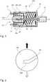
1 eine schematische Querschnittsansicht eines Kupplungselements in einer Ebene parallel zur Längsachse des Kupplungselementgehäuses gemäß einer exemplarischen ersten Ausführungsform des Kupplungselements im dekonnektierten Zustand;2 einen Ausschnitt eines exemplarischen Endes eines fluidanschlussseitigen Gewindegangs mit einem orthogonalen Abschnitt in einer Draufsicht in Blickrichtung auf die Längsachse;3 einen Ausschnitt eines weiteren exemplarischen Endes eines fluidanschlussseitigen Gewindegangs mit einem rückversetzten Abschnitt in einer Draufsicht in Blickrichtung auf die Längsachse;4 eine schematische Querschnittsansicht eines Gegenkupplungselements in einer Ebene parallel zur Gegenkupplungselementlängsachse des Gegenkupplungselementgehäuses gemäß einer exemplarischen ersten Ausführungsform des Gegenkupplungselements im dekonnektierten Zustand;5 eine schematische Querschnittsansicht eines Kupplungssystems mit einem Kupplungselement gemäß1 und einem Gegenkupplungselement gemäß4 in einer Ebene parallel zur Längsachse im dekonnektierten Zustand, in dem das Gegenkupplungselement durch das Kupplungselement gehalten wird;6 eine schematische Querschnittsansicht eines Kupplungssystems gemäß5 in einer Ebene parallel zur Längsachse im konnektierten Zustand;7 eine Übersicht aller Außenansichten des Kupplungssystems gemäß den4 und5 , der Schnittansichten entlang der Schnittlinie A-A und Schnittlinie B-B sowie eine perspektivische Ansicht im dekonnektierten Zustand;8 eine Übersicht aller Außenansichten des Kupplungssystems gemäß7 bzw. den4 und5 , der Schnittansichten entlang der Schnittlinie A-A und Schnittlinie B-B sowie eine perspektivische Ansicht in einem dekonnektierten Zustand, in dem das Gegenkupplungselement durch das Kupplungselement gehalten wird;9 eine Übersicht aller Außenansichten des Kupplungssystems gemäß den7 und8 bzw. den4 und5 , der Schnittansichten entlang der Schnittlinie A-A und Schnittlinie B-B sowie eine perspektivische Ansicht im konnektierten Zustand.
1 a schematic cross-sectional view of a coupling element in a plane parallel to the longitudinal axis of the coupling element housing according to an exemplary first embodiment of the coupling element in the disconnected state;2 a section of an exemplary end of a fluid connection-side thread with an orthogonal section in a plan view in the direction of view of the longitudinal axis;3 a detail of a further exemplary end of a fluid connection-side thread with a recessed portion in a plan view in the direction of view of the longitudinal axis;4th a schematic cross-sectional view of a mating coupling element in a plane parallel to the mating coupling element longitudinal axis of the mating coupling element housing according to an exemplary first embodiment of the mating coupling element in the disconnected state;5 a schematic cross-sectional view of a coupling system with a coupling element according to1 and a mating coupling element according to4th in a plane parallel to the longitudinal axis in the disconnected state, in which the mating coupling element is held by the coupling element;6th a schematic cross-sectional view of a coupling system according to5 in a plane parallel to the longitudinal axis in the connected state;7th an overview of all external views of the coupling system according to the4th and5 , the sectional views along the section line AA and section line BB and a perspective view in the disconnected state;8th an overview of all external views of the coupling system according to7th or the4th and5 , the sectional views along the section line AA and section line BB and a perspective view in a disconnected state in which the mating coupling element is held by the coupling element;9 an overview of all external views of the coupling system according to the7th and8th or the4th and5 , the sectional views along the section line AA and section line BB and a perspective view in the connected state.
Das Kupplungselementgehäuse
Im dargestellten dekonnektierten Zustand befindet sich die Dichtelementaufnahme
Zudem weist die Dichtelementaufnahme
Das Dichtelement
Die Bewegung der Dichtelementaufnahme
Sofern ein eigenständiges Ein- oder Ausschrauben grundsätzlich möglich ist oder auch aus anderen Sicherungsüberlegungen heraus, kann es vorteilhaft sein, eine Position der jeweiligen Dichtelementaufnahmeführungsstrukturen
Alternativ zeigt
Zur Lösung der Positionssicherung über den rückversetzten Abschnitt
Das Gegenkupplungselementgehäuse
Zudem weist das Gegenkupplungselementgehäuse
Anhand der
In dem dargestellten dekonnektierten Zustand befinden sich Schnapphaken
Hierzu zeigt
Durch Drehung der Dichtelementaufnahme
In dieser Ausführungsform ist der Gehäuseabschnitt
Die Erfindung ist nicht auf die beschriebenen Ausführungsformen beschränkt. Insbesondere sind bestimmte Merkmale einer Ausführungsform grundsätzlich auch auf andere Ausführungsformen anwendbar, sofern sich dies nicht vernünftigerweise ausschließt.The invention is not restricted to the embodiments described. In particular, certain features of an embodiment can in principle also be applied to other embodiments, unless this is reasonably excluded.
BezugszeichenlisteList of reference symbols
- 1010
- KupplungselementgehäuseCoupling element housing
- 10a10a
- GehäuseabschnittHousing section
- 10b10b
- KupplungsgehäusegewindeabschnittCoupling housing threaded section
- 10c10c
- GewindegangThread
- 10d10d
- orthogonaler Abschnitt (Gewindegang)orthogonal section (thread)
- 10e10e
- rückversetzter Abschnitt (Gewindegang)recessed section (thread)
- 1111
- DornaufnahmeMandrel holder
- 1212th
- FluidanschlussFluid connection
- 1313th
- KupplungsseiteClutch side
- 2020th
- DichtelementaufnahmeSealing element holder
- 20a20a
- DichtelementaufnahmeführungsstrukturSealing element receiving guide structure
- 2121
- DichtelementSealing element
- 2222nd
- kupplungselementseitige Befestigungsstrukturfastening structure on the coupling element side
- 22a22a
- SchnapphakenSnap hook
- 3030th
- Dornmandrel
- 3131
- FluidöffnungFluid opening
- 4040
- elastisches Elementelastic element
- 5050
- GegenkupplungselementgehäuseCounter coupling element housing
- 5151
- GegenkupplungselementfluidanschlussMating coupling element fluid connection
- 5252
- GegenkupplungsseiteMating coupling side
- 5353
- BefestigungsabschnittFastening section
- 5454
- gegenkupplungselementseitige BefestigungsstrukturCounter-coupling element-side fastening structure
- 54a54a
- AussparungRecess
- 5555
- EntriegelungsmechanismusRelease mechanism
- 5656
- GegenkupplungselementfluidkanalMating coupling element fluid channel
- 6060
- GegenkupplungselementdichtelementMating coupling element sealing element
- 100100
- KupplungselementCoupling element
- 200200
- GegenkupplungselementMating coupling element
- 300300
- KupplungssystemCoupling system
- L1L1
- Längsachse (Kupplungselement)Longitudinal axis (coupling element)
- L2L2
- GegenkupplungselementlängsachseMating coupling element longitudinal axis
Claims (15)
Translated fromGermanPriority Applications (5)
| Application Number | Priority Date | Filing Date | Title |
|---|---|---|---|
| DE102020202935.0ADE102020202935A1 (en) | 2020-03-06 | 2020-03-06 | Coupling element for a closed fluid transfer system, mating coupling element for such a coupling element and coupling system |
| US17/907,995US12048827B2 (en) | 2020-03-06 | 2021-03-03 | Coupling element for a closed fluid transfer system, counter coupling element for a coupling element of this type, and coupling system |
| CN202180017871.2ACN115209944B (en) | 2020-03-06 | 2021-03-03 | Coupling member for closing a fluid delivery system, mating coupling member for such coupling member, and coupling system |
| EP21710219.3AEP4114500A1 (en) | 2020-03-06 | 2021-03-03 | Coupling element for a closed fluid transfer system, counter coupling element for a coupling element of this type, and coupling system |
| PCT/EP2021/055249WO2021175884A1 (en) | 2020-03-06 | 2021-03-03 | Coupling element for a closed fluid transfer system, counter coupling element for a coupling element of this type, and coupling system |
Applications Claiming Priority (1)
| Application Number | Priority Date | Filing Date | Title |
|---|---|---|---|
| DE102020202935.0ADE102020202935A1 (en) | 2020-03-06 | 2020-03-06 | Coupling element for a closed fluid transfer system, mating coupling element for such a coupling element and coupling system |
Publications (1)
| Publication Number | Publication Date |
|---|---|
| DE102020202935A1true DE102020202935A1 (en) | 2021-09-09 |
Family
ID=74859418
Family Applications (1)
| Application Number | Title | Priority Date | Filing Date |
|---|---|---|---|
| DE102020202935.0APendingDE102020202935A1 (en) | 2020-03-06 | 2020-03-06 | Coupling element for a closed fluid transfer system, mating coupling element for such a coupling element and coupling system |
Country Status (5)
| Country | Link |
|---|---|
| US (1) | US12048827B2 (en) |
| EP (1) | EP4114500A1 (en) |
| CN (1) | CN115209944B (en) |
| DE (1) | DE102020202935A1 (en) |
| WO (1) | WO2021175884A1 (en) |
Families Citing this family (4)
| Publication number | Priority date | Publication date | Assignee | Title |
|---|---|---|---|---|
| US20230321425A1 (en)* | 2022-04-07 | 2023-10-12 | Carefusion 303, Inc. | Fluid connector system |
| WO2023229704A1 (en)* | 2022-05-23 | 2023-11-30 | Colder Products Company | Aseptic fluid couplings |
| US20250001155A1 (en)* | 2023-06-27 | 2025-01-02 | Carefusion 303, Inc. | Fluid connector assembly |
| WO2025037621A1 (en)* | 2023-08-17 | 2025-02-20 | テルモ株式会社 | Male connector |
Citations (3)
| Publication number | Priority date | Publication date | Assignee | Title |
|---|---|---|---|---|
| US20130076019A1 (en) | 2010-06-30 | 2013-03-28 | Terumo Kabushiki Kaisha | Connector and connector assembly |
| EP3517164A1 (en) | 2016-09-26 | 2019-07-31 | Terumo Kabushiki Kaisha | Male connector, medical instrument, and connection method |
| WO2019187839A1 (en) | 2018-03-27 | 2019-10-03 | テルモ株式会社 | Medical instrument |
Family Cites Families (94)
| Publication number | Priority date | Publication date | Assignee | Title |
|---|---|---|---|---|
| DE3873579T2 (en) | 1987-04-02 | 1993-03-18 | Drg Flexpak Ltd | DEVICE FOR MATCHING SUBSTANCES, LIKE MEDICINAL PRODUCTS, WITH A LIQUID. |
| US5514117A (en)* | 1988-09-06 | 1996-05-07 | Lynn; Lawrence A. | Connector having a medical cannula |
| US5201717A (en) | 1990-12-05 | 1993-04-13 | Philip Wyatt | Safety enclosure |
| US5122123A (en)* | 1991-01-30 | 1992-06-16 | Vaillancourt Vincent L | Closed system connector assembly |
| US6402207B1 (en) | 1997-06-09 | 2002-06-11 | Qd Enterprises, Llc | Safety indexed medical connectors |
| US6706022B1 (en) | 1999-07-27 | 2004-03-16 | Alaris Medical Systems, Inc. | Needleless medical connector with expandable valve mechanism |
| US7004934B2 (en) | 2001-09-06 | 2006-02-28 | Vaillancourt Vincent L | Closed system connector assembly |
| FR2836832B1 (en) | 2002-03-08 | 2005-02-04 | Optis France Sa | CONNECTION ASSEMBLY FOR MEDICAL USE FOR THE TRANSFER OF FLUIDS |
| CN100531812C (en) | 2002-08-22 | 2009-08-26 | 舍伍德服务公开股份有限公司 | Sliding seal connector for feeding systems |
| US20070066965A1 (en)* | 2003-07-14 | 2007-03-22 | Coambs David J | Coupling device for medical lines |
| US7396051B2 (en) | 2005-01-14 | 2008-07-08 | Baxa Corporation | Swabable fluid connectors and fluid connector pairs |
| US20070060904A1 (en) | 2005-03-14 | 2007-03-15 | Becton, Dickinson And Company | Filling system and method for syringes with short needles |
| US20070088293A1 (en) | 2005-07-06 | 2007-04-19 | Fangrow Thomas F Jr | Medical connector with closeable male luer |
| US7998134B2 (en) | 2007-05-16 | 2011-08-16 | Icu Medical, Inc. | Medical connector |
| JP5106110B2 (en) | 2005-08-19 | 2012-12-26 | 成男 太田 | Remove harmful active oxygen and / or free radicals in vivo |
| US7670326B2 (en) | 2006-09-25 | 2010-03-02 | Teva Medical Ltd.. | Syringe adapter element in drug mixing system |
| KR101507841B1 (en) | 2007-04-23 | 2015-04-07 | 플라스트메드 리미티드 | Method and apparatus for contamination-free transfer of a hazardous drug |
| AU2013200393B2 (en) | 2007-04-23 | 2014-05-01 | Equashield Medical Ltd | Method and apparatus for contamination-free transfer of a hazardous drug |
| ES2511692T3 (en) | 2007-09-11 | 2014-10-23 | Carmel Pharma Ab | Drill Element Protection Device |
| US8287513B2 (en) | 2007-09-11 | 2012-10-16 | Carmel Pharma Ab | Piercing member protection device |
| WO2009060419A2 (en) | 2007-11-08 | 2009-05-14 | Elcam Medical A.C.A..L. Ltd | Vial adaptor and manufacturing method therfor |
| US20110106046A1 (en)* | 2008-05-02 | 2011-05-05 | Terumo Kabushiki Kaisha | Connector assembly |
| EP2298406B1 (en) | 2008-05-02 | 2014-07-02 | Terumo Kabushiki Kaisha | Connector assembly |
| WO2009148969A1 (en) | 2008-06-02 | 2009-12-10 | Sta-Med, Llc | Needle cover assembly for a syringe |
| US20110282298A1 (en) | 2008-12-09 | 2011-11-17 | Nadav Agian | Device for injecting fluid isolated from microneedle hub with dead-space-reducing insert |
| CA2760570C (en) | 2009-05-04 | 2018-01-02 | Carmel Pharma Ab | Improved sealing barrier arrangement |
| EP2480281B1 (en)* | 2009-09-04 | 2018-11-07 | B. Braun Melsungen AG | Selectively sealable male needleless connectors |
| AU2010312289B2 (en) | 2009-10-30 | 2015-04-23 | Duoject Medical Systems Inc. | Inter vial transfer system |
| US8790327B2 (en) | 2010-03-30 | 2014-07-29 | Terumo Kabushiki Kaisha | Connector and connector assembly |
| AU2014277764B2 (en) | 2010-05-27 | 2016-04-21 | J&J Solutions, Inc. | Closed fluid transfer system |
| MX348044B (en) | 2010-05-27 | 2017-05-25 | J&J Solutions Inc | Closed fluid transfer system. |
| EP2589368A1 (en) | 2010-06-30 | 2013-05-08 | Terumo Kabushiki Kaisha | Connector and connector assembly |
| CN102958558A (en) | 2010-06-30 | 2013-03-06 | 泰尔茂株式会社 | Connector and connector assembly |
| WO2012078696A2 (en) | 2010-12-06 | 2012-06-14 | Aktivpak, Inc. | Aseptic cartridge and dispenser arrangement |
| WO2012098503A1 (en) | 2011-01-18 | 2012-07-26 | Nanopass Technologies Ltd. | Medication delivery assembly |
| WO2012117648A1 (en) | 2011-02-28 | 2012-09-07 | テルモ株式会社 | Connector assembly |
| IL214990A (en) | 2011-06-20 | 2013-06-27 | Teva Medical Ltd | Syringe adaptor assembly and system |
| ES2664517T3 (en) | 2011-09-09 | 2018-04-19 | Icu Medical, Inc. | Medical connectors with fluid resistant coupling interfaces |
| RU2623490C2 (en) | 2011-10-19 | 2017-06-26 | БАЙЕР ХелсКер ЛЛСи | Sterile maintaining medical connector unit and method |
| SG192310A1 (en) | 2012-02-02 | 2013-08-30 | Becton Dickinson Holdings Pte Ltd | Adaptor for coupling to a medical container |
| US10206854B2 (en) | 2012-03-05 | 2019-02-19 | Becton, Dickinson And Company | Transfer set with floating needle for drug reconstitution |
| JP5510986B2 (en) | 2012-04-02 | 2014-06-04 | 株式会社メディカルクリエーション | Drug transfer device |
| JP6094829B2 (en) | 2012-04-13 | 2017-03-15 | 株式会社ジェイ・エム・エス | Male connector with locking mechanism |
| JP6094830B2 (en) | 2012-04-13 | 2017-03-15 | 株式会社ジェイ・エム・エス | Male connector with locking mechanism |
| EP2838602A4 (en) | 2012-04-17 | 2016-04-20 | Py Inst Llc Dr | Self closing connector |
| JP5896228B2 (en) | 2012-04-26 | 2016-03-30 | 株式会社ジェイ・エム・エス | Medical connector |
| BR112015010607A2 (en) | 2012-11-09 | 2017-12-05 | Iinjec Tech Inc | fluid delivery injector, retractable needle assembly, and method for injecting at least one dose of a transcutaneously fluid medication into the body. |
| CN105008227B (en) | 2013-02-07 | 2017-03-08 | 伊奎希尔德医疗有限公司 | Improvements to closed drug delivery systems |
| US20140263322A1 (en) | 2013-03-14 | 2014-09-18 | Salah Ghodbane | Coring-free valve system |
| US9597260B2 (en) | 2013-03-15 | 2017-03-21 | Becton Dickinson and Company Ltd. | System for closed transfer of fluids |
| IL226281A (en) | 2013-05-09 | 2017-01-31 | Kriheli Marino | Needle valve and connectors for use in liquid transfer apparatuses |
| WO2015017858A1 (en) | 2013-08-02 | 2015-02-05 | J&J SOLUTIONS, INC. d.b.a CORVIDA MEDICAL | Compounding systems and methods for safe medicament transport |
| EP3065694B1 (en) | 2013-11-06 | 2020-04-29 | Becton Dickinson and Company Limited | System for closed transfer of fluids having connector |
| ES2780857T3 (en) | 2013-11-06 | 2020-08-27 | Becton Dickinson & Co Ltd | Connection device for a medical device |
| ES2780856T3 (en)* | 2013-11-06 | 2020-08-27 | Becton Dickinson & Co Ltd | Medical connector having locking coupling |
| CA2929476C (en) | 2013-11-06 | 2019-01-22 | Becton Dickinson and Company Limited | System for closed transfer of fluids with a locking member |
| US9987477B2 (en) | 2014-02-10 | 2018-06-05 | Nexus Medical, Llc | Split septum assembly for an intravenous injection site |
| US10137237B2 (en) | 2014-04-03 | 2018-11-27 | Novo Nordisk A/S | Needle arrangement |
| EP4091597A1 (en) | 2014-04-21 | 2022-11-23 | Becton Dickinson and Company Limited | Syringe adapter with disconnection feedback mechanism |
| EP3134057B1 (en) | 2014-04-21 | 2018-06-27 | Becton Dickinson and Company Limited | Syringe adapter with compound motion disengagement |
| BR112016024680B8 (en) | 2014-04-21 | 2021-11-09 | Becton Dickinson & Co Ltd | Syringe adapter |
| AU2015249915B2 (en) | 2014-04-21 | 2017-11-30 | Becton Dickinson and Company Limited | System for closed transfer of fluids |
| JP6456978B2 (en) | 2014-05-13 | 2019-01-23 | ノボ・ノルデイスク・エー/エス | Medical injection device having a cleaning reservoir |
| US10058693B2 (en) | 2014-05-23 | 2018-08-28 | Applied Medical Technology, Inc. | Interlock feed set coupling |
| IL234746A0 (en) | 2014-09-18 | 2014-11-30 | Equashield Medical Ltd | Improved needle valve and connectors for use in liquid transfer apparatuses |
| DE102015201285B3 (en) | 2015-01-26 | 2016-06-30 | Bayer Pharma AG | Device for transferring a liquid between a storage container and at least one further use container and set of transfer device and storage container |
| EP3067037B1 (en) | 2015-03-09 | 2017-10-04 | Epsilon Elektronik Sanayi ve Ticaret A.S. | A safety medical transfer device |
| IL237788B (en) | 2015-03-16 | 2019-10-31 | Kriheli Marino | Septum holders for use in syringe connectors |
| IL239366B (en) | 2015-06-11 | 2018-07-31 | Kriheli Marino | Components of a fluid transfer apparatus |
| BR112017026574B1 (en) | 2015-06-12 | 2022-04-26 | Becton Dickinson and Company Limited | Syringe adapter with rotating connector |
| CA3001858C (en) | 2015-10-13 | 2021-03-23 | J&J SOLUTIONS, INC. d/b/a Corvida Medical | Automated compounding equipment for closed fluid transfer system |
| IL243108B (en) | 2015-12-22 | 2018-08-30 | Kriheli Marino | Connector section |
| US10022531B2 (en) | 2016-01-21 | 2018-07-17 | Teva Medical Ltd. | Luer lock adaptor |
| IL245289B (en) | 2016-04-21 | 2019-03-31 | Kriheli Marino | A septum holder with moveable septum |
| SE1651467A1 (en) | 2016-11-09 | 2018-05-10 | Tada Medical Ab | Coupling device |
| EP3570931B1 (en) | 2017-01-17 | 2023-06-07 | Becton Dickinson and Company Limited | Syringe adapter with lock mechanism |
| ES2949067T3 (en) | 2017-01-17 | 2023-09-25 | Becton Dickinson & Co Ltd | Syringe adapter for closed fluid transfer |
| IL268043B2 (en) | 2017-01-17 | 2023-10-01 | Becton Dickinson & Co Ltd | Connector for a closed fluid transfer system |
| WO2018186276A1 (en) | 2017-04-04 | 2018-10-11 | ニプロ株式会社 | Connector |
| CA3072311A1 (en) | 2017-08-10 | 2019-02-14 | Simplivia Healthcare Ltd. | Syringe adaptor and complementary fluid-port adaptor |
| WO2019033004A1 (en) | 2017-08-11 | 2019-02-14 | Modernatx, Inc. | Aseptic connector for fluidic connections |
| CA3070228C (en) | 2017-08-15 | 2022-05-03 | Becton, Dickinson And Company | Spinning female luer with threadably removable feature |
| ES2802484T3 (en) | 2017-08-24 | 2021-01-19 | Epic Medical Pte Ltd | Vial adapter and liquid transfer system |
| WO2019086589A1 (en) | 2017-11-02 | 2019-05-09 | F. Hoffmann-La Roche Ag | Container adapter, delivery assembly and method of delivering a liquid to a patient |
| CN111526855B (en) | 2018-01-04 | 2024-06-07 | 爱康医学农业合作协会有限公司 | Vial adapter assembly for closed fluid delivery system |
| IL257417B (en) | 2018-02-08 | 2020-11-30 | Kriheli Marino | Improved components of a fluid transfer apparatus |
| IL257415B (en) | 2018-02-08 | 2020-01-30 | Kriheli Marino | Improved components of a fluid transfer apparatus |
| IL257778B (en) | 2018-02-27 | 2022-07-01 | Equashield Medical Ltd | Device for securing device connections |
| US11413216B2 (en) | 2018-03-20 | 2022-08-16 | Becton Dickinson and Company Limited | Connection arrangement for closed system transfer of fluids |
| AU2019257279B2 (en) | 2018-04-19 | 2022-03-31 | Becton Dickinson and Company Limited | Syringe adapter with aspiration assembly |
| IL261024B2 (en) | 2018-08-07 | 2023-07-01 | Equashield Medical Ltd | A septum holder with moveable septum |
| DE102019116970B4 (en) | 2019-06-24 | 2023-11-30 | Sartorius Stedim Biotech Gmbh | Sterile connector for the sterile transfer of a liquid medium |
| IL268368B2 (en) | 2019-07-30 | 2023-11-01 | Equashield Medical Ltd | Ingredients for open systems of liquid drug delivery and a robotic system that utilizes them |
| US10945922B1 (en) | 2019-09-26 | 2021-03-16 | Abyssal Systems, Inc. | Apparatus for creating a sealed conduit between separate volumes |
- 2020
- 2020-03-06DEDE102020202935.0Apatent/DE102020202935A1/enactivePending
- 2021
- 2021-03-03CNCN202180017871.2Apatent/CN115209944B/enactiveActive
- 2021-03-03USUS17/907,995patent/US12048827B2/enactiveActive
- 2021-03-03EPEP21710219.3Apatent/EP4114500A1/enactivePending
- 2021-03-03WOPCT/EP2021/055249patent/WO2021175884A1/ennot_activeCeased
Patent Citations (3)
| Publication number | Priority date | Publication date | Assignee | Title |
|---|---|---|---|---|
| US20130076019A1 (en) | 2010-06-30 | 2013-03-28 | Terumo Kabushiki Kaisha | Connector and connector assembly |
| EP3517164A1 (en) | 2016-09-26 | 2019-07-31 | Terumo Kabushiki Kaisha | Male connector, medical instrument, and connection method |
| WO2019187839A1 (en) | 2018-03-27 | 2019-10-03 | テルモ株式会社 | Medical instrument |
Also Published As
| Publication number | Publication date |
|---|---|
| WO2021175884A1 (en) | 2021-09-10 |
| CN115209944B (en) | 2024-12-10 |
| US12048827B2 (en) | 2024-07-30 |
| CN115209944A (en) | 2022-10-18 |
| US20230092208A1 (en) | 2023-03-23 |
| EP4114500A1 (en) | 2023-01-11 |
Similar Documents
| Publication | Publication Date | Title |
|---|---|---|
| DE102020202935A1 (en) | Coupling element for a closed fluid transfer system, mating coupling element for such a coupling element and coupling system | |
| DE60120293T2 (en) | Catheter connector device | |
| EP0063333B1 (en) | Connector for medical instruments or tubes | |
| DE102019217984A1 (en) | Coupling element for a closed fluid transfer system, mating coupling element for such a coupling element and coupling system | |
| DE102020203153A1 (en) | Coupling element for a closed fluid transfer system, attachment for such a coupling element, coupling system and coupling kit | |
| DE69624464T2 (en) | CONNECTOR FOR A LIQUID TRANSFER KIT WITH A LOCKABLE CAP AND METHOD FOR USE | |
| EP3313501A1 (en) | Connection system | |
| DE102021108157A1 (en) | Fluid transfer device and closed drug delivery system | |
| EP0947213A2 (en) | Patient connector | |
| DE19825751A1 (en) | Throw-away intravenous injection safety syringe with a special retractable needle | |
| EP2710972B1 (en) | Rotating valve body for a discharge device for bone cements | |
| EP3310426B1 (en) | Male and female luer connector and luer connection system | |
| WO2021089754A1 (en) | Counterpin coupling element, pin coupling element and coupling system for a closed fluid transfer system | |
| DE202015104332U1 (en) | hose coupling | |
| WO2021175881A1 (en) | Coupling element and coupling system for a closed fluid transfer system | |
| EP0063640A2 (en) | Connecting device for conduits in medical apparatuses | |
| DE202012101283U1 (en) | connector | |
| EP2379161B1 (en) | Device for feeding medical fluids | |
| DE102020202939A1 (en) | Coupling element for a closed fluid transfer system, mating coupling element for such a coupling element and coupling system | |
| DE2212656B2 (en) | Quick release coupling for speech and air connection - has push=in nipple containing telephone cables for connection to gas protection suit | |
| DE102005030319B4 (en) | Connector, connector system and use | |
| DE102019115639A1 (en) | Nasal cannula with improved secured connection to a supply line | |
| EP0893094B1 (en) | Blood sampling device | |
| EP3209264B1 (en) | Peg-tube with protected manual valve operation | |
| EP4620510A1 (en) | Assembly comprising a component for a blood pump and a connector |
Legal Events
| Date | Code | Title | Description |
|---|---|---|---|
| R079 | Amendment of ipc main class | Free format text:PREVIOUS MAIN CLASS: F16L0037000000 Ipc:F16L0037300000 | |
| R163 | Identified publications notified | ||
| R082 | Change of representative | Representative=s name:MAIWALD GMBH, DE |