DE102020134240A1 - Diamond-forming maxillary reduction implant - Google Patents
Diamond-forming maxillary reduction implantDownload PDFInfo
- Publication number
- DE102020134240A1 DE102020134240A1DE102020134240.3ADE102020134240ADE102020134240A1DE 102020134240 A1DE102020134240 A1DE 102020134240A1DE 102020134240 ADE102020134240 ADE 102020134240ADE 102020134240 A1DE102020134240 A1DE 102020134240A1
- Authority
- DE
- Germany
- Prior art keywords
- section
- maxilla
- plate
- implant
- screw hole
- Prior art date
- Legal status (The legal status is an assumption and is not a legal conclusion. Google has not performed a legal analysis and makes no representation as to the accuracy of the status listed.)
- Pending
Links
Images

Classifications
- A—HUMAN NECESSITIES
- A61—MEDICAL OR VETERINARY SCIENCE; HYGIENE
- A61B—DIAGNOSIS; SURGERY; IDENTIFICATION
- A61B17/00—Surgical instruments, devices or methods
- A61B17/56—Surgical instruments or methods for treatment of bones or joints; Devices specially adapted therefor
- A61B17/58—Surgical instruments or methods for treatment of bones or joints; Devices specially adapted therefor for osteosynthesis, e.g. bone plates, screws or setting implements
- A61B17/68—Internal fixation devices, including fasteners and spinal fixators, even if a part thereof projects from the skin
- A61B17/80—Cortical plates, i.e. bone plates; Instruments for holding or positioning cortical plates, or for compressing bones attached to cortical plates
- A61B17/8061—Cortical plates, i.e. bone plates; Instruments for holding or positioning cortical plates, or for compressing bones attached to cortical plates specially adapted for particular bones
- A61B17/8071—Cortical plates, i.e. bone plates; Instruments for holding or positioning cortical plates, or for compressing bones attached to cortical plates specially adapted for particular bones for the jaw
- A—HUMAN NECESSITIES
- A61—MEDICAL OR VETERINARY SCIENCE; HYGIENE
- A61B—DIAGNOSIS; SURGERY; IDENTIFICATION
- A61B17/00—Surgical instruments, devices or methods
- A61B17/56—Surgical instruments or methods for treatment of bones or joints; Devices specially adapted therefor
- A61B17/58—Surgical instruments or methods for treatment of bones or joints; Devices specially adapted therefor for osteosynthesis, e.g. bone plates, screws or setting implements
- A61B17/68—Internal fixation devices, including fasteners and spinal fixators, even if a part thereof projects from the skin
- A61B17/80—Cortical plates, i.e. bone plates; Instruments for holding or positioning cortical plates, or for compressing bones attached to cortical plates
- A61B17/8085—Cortical plates, i.e. bone plates; Instruments for holding or positioning cortical plates, or for compressing bones attached to cortical plates with pliable or malleable elements or having a mesh-like structure, e.g. small strips
- A—HUMAN NECESSITIES
- A61—MEDICAL OR VETERINARY SCIENCE; HYGIENE
- A61B—DIAGNOSIS; SURGERY; IDENTIFICATION
- A61B17/00—Surgical instruments, devices or methods
- A61B17/56—Surgical instruments or methods for treatment of bones or joints; Devices specially adapted therefor
- A61B2017/568—Surgical instruments or methods for treatment of bones or joints; Devices specially adapted therefor produced with shape and dimensions specific for an individual patient
- A—HUMAN NECESSITIES
- A61—MEDICAL OR VETERINARY SCIENCE; HYGIENE
- A61B—DIAGNOSIS; SURGERY; IDENTIFICATION
- A61B17/00—Surgical instruments, devices or methods
- A61B17/56—Surgical instruments or methods for treatment of bones or joints; Devices specially adapted therefor
- A61B17/58—Surgical instruments or methods for treatment of bones or joints; Devices specially adapted therefor for osteosynthesis, e.g. bone plates, screws or setting implements
- A61B17/68—Internal fixation devices, including fasteners and spinal fixators, even if a part thereof projects from the skin
- A61B2017/681—Alignment, compression, or distraction mechanisms
- A—HUMAN NECESSITIES
- A61—MEDICAL OR VETERINARY SCIENCE; HYGIENE
- A61B—DIAGNOSIS; SURGERY; IDENTIFICATION
- A61B90/00—Instruments, implements or accessories specially adapted for surgery or diagnosis and not covered by any of the groups A61B1/00 - A61B50/00, e.g. for luxation treatment or for protecting wound edges
- A61B90/03—Automatic limiting or abutting means, e.g. for safety
- A61B2090/037—Automatic limiting or abutting means, e.g. for safety with a frangible part, e.g. by reduced diameter
Landscapes
- Health & Medical Sciences (AREA)
- Orthopedic Medicine & Surgery (AREA)
- Surgery (AREA)
- Life Sciences & Earth Sciences (AREA)
- Heart & Thoracic Surgery (AREA)
- Animal Behavior & Ethology (AREA)
- Engineering & Computer Science (AREA)
- Biomedical Technology (AREA)
- Neurology (AREA)
- Medical Informatics (AREA)
- Molecular Biology (AREA)
- Nuclear Medicine, Radiotherapy & Molecular Imaging (AREA)
- General Health & Medical Sciences (AREA)
- Public Health (AREA)
- Veterinary Medicine (AREA)
- Surgical Instruments (AREA)
- Materials For Medical Uses (AREA)
- Dental Prosthetics (AREA)
Abstract
Translated fromGermanDescription
Translated fromGermanDie Erfindung betrifft ein Maxilla-Repositionsimplantat zum dreidimensionalen exakten Ausrichten eines Maxilla-Verlagerungsabschnitts relativ zu einem schädelfesten Maxilla-Restabschnitt. Als Maxilla wird hier, wie üblich, der menschliche Oberkieferknochen bezeichnet. Ein Teil des Oberkieferknochens kann mittels eines chirurgischen Eingriffs vollständig vom Rest des Oberkiefers getrennt werden. Dadurch lässt sich ein Maxilla-Verlagerungsabschnitt von einem schädelfesten Maxilla-Restabschnitt entfernen. Auf diese Weise können Fehlstellungen im Kiefer behoben werden. Der Maxilla-Restabschnitt ist jedoch nach der Verlagerung wieder am Maxilla-Verlagerungsabschnitt zu befestigen. Dafür werden üblicherweise Maxilla-Repositionsimplantate eingesetzt.The invention relates to a maxilla repositioning implant for the three-dimensional, precise alignment of a maxilla displacement section relative to a remaining maxilla section that is fixed to the skull. As usual, the human upper jaw bone is referred to as the maxilla. Part of the upper jaw bone can be completely separated from the rest of the upper jaw by means of a surgical procedure. This allows a maxillary displacement section to be removed from a residual maxillary section that is fixed to the skull. In this way, misalignments in the jaw can be corrected. However, after the displacement, the residual section of the maxilla must be reattached to the section of the maxilla that has been displaced. Maxilla reduction implants are usually used for this.
Solche Maxilla-Repositionsimplantate sind aus diversen Druckschriften bereits bekannt, so etwa aus der
Dort ist ein präoperativ maßgefertigtes Implantat zur Verwendung in der orthognathen Chirurgie offenbart. Bei der orthognathen Chirurgie wird ein erster Teil eines Oberkiefers von einem zweiten Teil des Oberkiefers getrennt und im Rahmen dieses Verfahrens dann das Implantat eingesetzt. Das Implantat umfasst ein Plattenbauteil, das vorgeformt ist, zu einer präoperativen Form des Oberkiefers zu korrespondieren und mehrere nichtlineare Wellungen enthält, die zu bestimmten Oberflächenteilen des ersten Teils des Oberkiefers korrespondieren, wobei das Plattenbauteil zumindest eine Fixieröffnung definiert, dieses sich durch das Plattenbauteil hindurch erstreckt und eingerichtet ist, ein Knochenfixierelement aufzunehmen, um das Plattenbauteil am ersten Teil des Oberkiefers zu befestigen. Ferner sind eine Mehrzahl von (freien) Finger vorhanden, die sich weg von dem Plattenbauteil erstrecken, wobei die (freien) Finger vorgeformt sind, zur Form des zweiten Teil des Oberkiefers zu korrespondieren und mehrere nichtlineare Wellungen enthalten, die zu bestimmten Oberflächenteilen des zweiten Teils des Oberkiefers korrespondieren.There, a preoperatively custom-made implant for use in orthognathic surgery is disclosed. Orthognathic surgery involves separating a first part of an upper jaw from a second part of the upper jaw and then inserting the implant as part of the procedure. The implant includes a plate member that is preformed to correspond to a preoperative shape of the maxilla and includes a plurality of non-linear corrugations that correspond to certain surface portions of the first portion of the maxilla, the plate member defining at least one fixation opening that extends through the plate member and configured to receive a bone fixation element to secure the plate member to the first portion of the maxilla. There are also a plurality of (free) fingers extending away from the plate member, the (free) fingers being preformed to correspond to the shape of the second part of the maxilla and containing a plurality of non-linear undulations corresponding to certain surface parts of the second part of the upper jaw correspond.
Benachbarte Dokumente offenbaren ähnliche Implantate, wie bspw. die
Die bekannten Implantate haben jedoch immer Nachteile. Insbesondere sind diese Implantate schwierig zu fertigen. Auch ist häufig die Stabilität nicht ausreichend. Werden die Implantate am Knochen verbaut und wieder mit Weichteilmaterial, wie Haut und Bindegewebe bedeckt, so ergibt sich ein unästhetisches Äußeres, was noch dazu einen unangenehmen Tragekomfort für den Patienten nach sich zieht. Häufig gibt es dazu Komplikationen und medizinisch negative Nebenwirkungen.However, the known implants always have disadvantages. In particular, these implants are difficult to manufacture. Stability is also often insufficient. If the implants are built into the bone and then covered again with soft tissue, such as skin and connective tissue, the result is an unaesthetic appearance, which also results in uncomfortable wearing comfort for the patient. There are often complications and medically negative side effects.
Ausgehend von einem Maxilla-Repositionsimplantat mit nachfolgenden Merkmalen hat sich die Erfindung die Aufgabe gesetzt diese Nachteile zu beseitigen. Darüber hinaus soll ein kosteneffizienteres Maxilla Repositionsimplantat unter Beseitigung auch anderer Nachteile geschaffen werden.Based on a maxilla repositioning implant with the following features, the invention has set itself the task of eliminating these disadvantages. In addition, a more cost-effective maxilla reduction implant is to be created while also eliminating other disadvantages.
Die Erfindung geht dabei von einem Maxilla-Repositionsimplantat aus, das eine Basis besitzt, die wenigstens eine Platte aufweist, in der Schraubenlöcher vorhanden sind, wobei ein Abschnitt des Materials der Platte als Rand je ein Schraubenloch definiert (d. h. teilweise oder vollständig umgibt), wobei das Schraubenloch zur Aufnahme einer Knochenschraube vorgesehen ist, um über die in das jeweilige Schraubenloch einzusetzende Knochenschraube eine Befestigung am schädelfesten Maxilla-Restabschnitt sicherzustellen, wobei das Maxilla-Repositionsimplantat darüber hinaus einen Anschlussabschnitt besitzt, der von der Basis über Verbindungsstege beabstandet ist, wobei der Anschlussabschnitt wenigstens eine Platte aufweist, in der ebenfalls Schraubenlöcher vorhanden sind und wobei ein Abschnitt des Materials der Platte als Rand je ein Schraubenloch definiert (d. h. teilweise oder auch vollständig das Schraubenloch umgibt), um über eine in das jeweilige Schraubenloch einzusetzende Knochenschraube eine Befestigung am Maxilla Verlagerungsabschnitt sicher zu stellen.The invention is based on a maxillary reduction implant that has a base that has at least one plate in which screw holes are present, with a section of the material of the plate defining a screw hole as an edge (i.e. partially or completely surrounding it), where the screw hole is provided for receiving a bone screw in order to ensure attachment to the skull-fixed maxillary residual section via the bone screw to be inserted into the respective screw hole, wherein the maxillary reduction implant also has a connecting section which is spaced from the base by connecting webs, the connecting section has at least one plate in which there are also screw holes and wherein a section of the material of the plate defines a screw hole as an edge (i.e. partially or completely surrounds the screw hole) in order to have a bone screw to be inserted into the respective screw hole e to ensure attachment to the maxillary displacement section.
Die eingangs genannte Aufgabe wird erfindungsgemäß dadurch gelöst, dass zwei Platten und die sie verbindenden Verbindungsstege rautenartig aufgespannt sind, d. h. einen rautenartigen Leerraum definieren, so kann eine besonders hochbelastbare Maxilla-Repositionsimplantat-Ausgestaltung realisiert werden.The object mentioned at the outset is achieved according to the invention in that two plates and the connecting webs connecting them are spanned in a rhombus shape, i. H. define a diamond-like empty space, a particularly heavy-duty maxillary reduction implant design can be realized.
Es wird durch ein solches Maxilla-Repositionsimplantat eine höhere Festigkeit bei spannungsoptimiertem Design möglich. Auch ist ein geringerer Materialeinsatz, als bei herkömmlichen Implantaten realisierbar. Eine gewebeverträglichere Ausgestaltung und die Beseitigung der eingangs genannten Nachteile ist die überraschende Folge. Eine besonders zur
Es sei daran erinnert, dass sowohl die Basis, als auch der Anschlussabschnitt bzgl. ihrer der Maxilla zugewandten Seite an die patientenspezifische Geometrie des Knochens angepasst ist. Die Oberflächenkontur der Maxilla ist sowohl im Bereich des Maxilla-Verlagerungsabschnitts, als auch im Bereich des schädelfesten Maxilla-Restabschnitts, mittels MRT-, CRT- und/oder Röntgen-Einsatz erhoben und mit nachfolgenden CAD- / CAM-Fertigungsverfahren in eine identische Kontur der Platte der Basis für den schädelfesten Maxilla Restabschnitt und der Platte des Anschlussabschnittes für den Maxilla-Verlagerungsabschnitt kopiert. Dabei können üblicherweise Sinterverfahren, wie Laser-Sinterverfahren, etwa das selektive Laser-Sinterverfahren, eingesetzt werden.It should be remembered that both the base and the connecting section are adapted to the patient-specific geometry of the bone with regard to their side facing the maxilla. the The surface contour of the maxilla is raised both in the area of the maxilla displacement section and in the area of the residual section of the maxilla that is fixed to the skull, using MRI, CRT and/or X-rays, and using subsequent CAD/CAM manufacturing processes to form an identical contour of the plate the base for the skull-fixed maxilla rest section and the plate of the connecting section for the maxilla displacement section. Usually, sintering methods such as laser sintering methods, such as the selective laser sintering method, can be used.
Für den Schutz im Ausland, insbesondere in den Vereinigten Staaten von Amerika sei darauf hingewiesen, dass die Erfindung auch ein Verfahren zum Einsetzen des Maxilla-Repositionsimplantates in/an den Patienten umfasst.For protection abroad, particularly in the United States of America, it should be noted that the invention also includes a method of inserting the maxillary reduction implant into/on the patient.
Die Erfindung betrifft jedoch auch ein Verfahren zum Fertigen des Maxilla Repositionsimplantates.However, the invention also relates to a method for manufacturing the maxilla reduction implant.
Vorteilhafte Ausführungsformen sind in den Unteransprüchen beansprucht und werden nachfolgend näher erläutert. Dabei ist es auch denkbar, dass diese Aspekte unabhängig davon weiter verfolgt werden, dass sich zwei Platten und die sie verbindenden Verbindungsstege rautenartig aufgespannt sind, d. h. einen rautenartigen Leerraum definieren sondern stattdessen oder zusätzlich von der Platte des Anschlussabschnittes (wenigstens oder nur / genau) zwei Verbindungsstege zum Rand eines (einzigen / bestimmten) Schraubenloches in der Platte der Basis erstrecken. Allerdings ist es selbstverständlich bevorzugt, wenn diese Merkmalskombination(en) auch bei den Ausführungsformen der Unteransprüche realisiert ist.Advantageous embodiments are claimed in the dependent claims and are explained in more detail below. It is also conceivable that these aspects will be pursued independently of the fact that two panels and the connecting webs connecting them are spanned in a rhombus shape, i. H. define a diamond-like void but instead or additionally extend from the plate of the terminal section (at least or only/precisely) two connecting webs to the edge of a (single/certain) screw hole in the plate of the base. However, it is of course preferred if this combination of features is/are also implemented in the embodiments of the dependent claims.
Um ein besonders gewebeschonendes Design - insbesondere zwischen Schraubenlochbefestigungspunkten am Knochen - zu realisieren, hat es sich bewährt, wenn jeder/der Verbindungssteg (vorzugsweise an wenigstens einer Stelle oder über die gesamte Länge des Verbindungssteges) einen elliptischen Querschnitt besitzt.In order to achieve a particularly tissue-friendly design, particularly between screw hole attachment points on the bone, it has proven useful if each connecting bar has an elliptical cross-section (preferably at least at one point or over the entire length of the connecting bar).
Für die Fertigung ist es dabei von Vorteil, wenn der elliptische Querschnitt an wenigstens einer Stelle oder über die gesamte Länge des Verbindungssteges gesehen, die spezielle Form eines Kreises einnimmt. Dabei ist es auch möglich, dass sich Abflachungen auf der maxilla-abgewandten Oberseite des Verbindungssteges zeigen und/oder der elliptische Querschnitt über die Länge gesehen variiert. Auch können Erhöhungen oder Vertiefungen, insbesondere Krümmungen eingebracht sein. Eine besonders ästhetische Erscheinung bei Bedeckung des Implantats bzw. der Implantatsabschnitte mit Weichgewebe ist nach dem Einsetzen des Implantats die vorteilhafte Folge.It is advantageous for production if the elliptical cross section assumes the special shape of a circle at least at one point or over the entire length of the connecting web. It is also possible that there are flat areas on the upper side of the connecting web facing away from the maxilla and/or the elliptical cross-section varies over the length. Elevations or depressions, in particular curvatures, can also be incorporated. A particularly aesthetic appearance when the implant or the implant sections are covered with soft tissue is the advantageous result after the implant has been inserted.
Der Stabilität ist es zuträglich, wenn die Platte der Basis und/oder die Platte des Anschlussabschnitts wenigstens eine Stelle besitzt, die eine größere Dicke als der Verbindungssteg (insbesondere an seiner dicksten Stelle) aufweist. In diesem Zusammenhang ist auch wünschenswert, dass die Verbindungsstege distinkt von den Bestandteilen der Platte ausgebildet sind und/oder die Fläche des Querschnitts des Verbindungssteges zwischen 70 % oder 80% und 120% (vorzugsweise 75% oder 100%) der Fläche des Schraubenloches beträgt oder die Breite des Verbindungssteges ungefähr dem Durchmesser eines der Schraubenlöcher entspricht.It is beneficial to stability if the plate of the base and/or the plate of the connection section has at least one point that is thicker than the connecting web (in particular at its thickest point). In this context, it is also desirable that the connecting webs are formed distinctly from the components of the plate and/or the area of the cross-section of the connecting web is between 70% or 80% and 120% (preferably 75% or 100%) of the area of the screw hole or the width of the connecting bar corresponds approximately to the diameter of one of the screw holes.
Der Präzision der Ausrichtung des Maxilla Verlagerungsabschnitts relativ zum schädelfesten Maxilla Restabschnitt ist es zuträglich, wenn jede Platte der Basis und jede Platte des Anschlussabschnitts über genau zwei Verbindungsstege miteinander verbunden sind. Ungewollte Belastungen nach Art von Verbiegungen und Verdrehungen, insbesondere bei einer schlecht vermeidbaren Torsion der Basis relativ zum Anschlussabschnitt während des Einsetzens des Implantats, führen dann nicht zu einer Fehlstellung der beiden Maxilla-Abschnitte. Ein besonders gutes medizinisches Ergebnis kann dadurch sichergestellt werden.The precision of the alignment of the maxilla displacement section relative to the remaining section of the maxilla that is fixed to the skull is beneficial if each plate of the base and each plate of the connecting section are connected to one another via exactly two connecting webs. Undesirable loads such as bending and twisting, in particular in the case of torsion of the base relative to the connecting section during insertion of the implant, which is difficult to avoid, then do not lead to a misalignment of the two maxilla sections. A particularly good medical result can be ensured in this way.
Wenn die Verbindungsstege vollständig oder überwiegend parallel zueinander verlaufen, ist ein besonders spannungsoptimiertes Design realisierbar. Die Kräfte werden dann gleichartig abgeleitet.If the connecting webs run completely or predominantly parallel to one another, a particularly stress-optimized design can be implemented. The forces are then derived in the same way.
Eine vorteilhafte Ausführungsform ist jedoch darüber hinaus dadurch gekennzeichnet, dass jeder Verbindungssteg ein erstes Ende und ein zweites Ende besitzt, wobei das erste Ende einmaterialig (integral / einheitlich) in den Rand eines ersten Schraubenloches der basisseitigen Platte übergeht und das zweite Ende einmaterialig (integral / einheitlich) in den Rand eines ersten Schraubenloches der anschlussabschlussseitigen Platte übergeht. Eine solch stufenlose Geometrie, die für den Patienten Entzündungen vermeidet, lässt sich dann realisieren. Darüber hinaus wird eine hohe Belastbarkeit des Implantats gewährleistet.However, an advantageous embodiment is also characterized in that each connecting web has a first end and a second end, with the first end merging into the edge of a first screw hole of the base-side plate in one material (integral/unitary) and the second end in one material (integral/ uniform) merges into the edge of a first screw hole of the terminal end-side plate. Such a stepless geometry, which avoids inflammation for the patient, can then be implemented. In addition, a high load capacity of the implant is guaranteed.
Im Zentrum der Erfindung steht ferner eine Ausführungsform, die dadurch gekennzeichnet ist, dass die basisseitige Platte über einen ersten Verbindungssteg und einen zweiten Verbindungssteg mit der anschlussseitigen Platte verbunden ist, wobei der erste Verbindungssteg und der zweite Verbindungssteg mit ihren ersten Enden an dem Rand eines einzigen ersten Schraubenlochs der basisseitigen Platte angreifen und a) entweder mit ihren zweiten Enden gemeinsam an dem Rand eines einzigen ersten Schraubenloches der anschlussabschnittseitigen Platte angreifen / daran befestigt sind / darin integriert sind oder b) der eine Verbindungssteg mit seinem zweiten Ende an dem Rand des ersten Schraubenlochs der anschlussabschnittseitigen Platte angreift / integriert ist und der andere Verbindungssteg an dem Rand eines zweiten Schraubenlochs der anschlussabschnittseitigen Platte angreift / integriert ist. Diese Ausführungsform bietet somit zwei Möglichkeiten realisiert zu werden, nämlich in einer besonders filigranen Variante (b) oder einer besonders stabilen Variante (a). Auch lassen sich dadurch geometrischen Besonderheiten auf der Oberfläche der Maxilla des speziellen, jeweils betroffenen Patienten Rechnung tragen. Besonders gute patientenspezifische Lösungen sind dann die Folge.The invention also focuses on an embodiment which is characterized in that the base-side plate is connected to the connection-side plate via a first connecting web and a second connecting web, the first connecting web and the second connecting web having their first ends on the edge of a single attack the first screw hole of the base-side plate and a) either with their second ends together on the edge of a single first screw hole of the connecting section-side plate engage / are attached to / are integrated therein or b) one connecting web engages / is integrated with its second end on the edge of the first screw hole of the connecting section-side plate and the other connecting web on the edge of a second screw hole of the connecting section-side plate attacks / is integrated. This embodiment thus offers two possibilities of being realized, namely in a particularly filigree variant (b) or in a particularly stable variant (a). In this way, it is also possible to take into account geometric peculiarities on the surface of the maxilla of the particular patient concerned. The result is particularly good patient-specific solutions.
Dabei hat es sich bewährt, wenn der zweite Verbindungssteg sich über die Länge von der basisseitigen Platte aus gesehen zunehmend von dem ersten Verbindungssteg entfernt (von wenigstens nahe des ersten Endes in Richtung nahe des zweiten Endes) und in einer Weiterbildung in einem dem zweiten Ende nahen Bericht dem ersten Verbindungssteg wieder näher kommt). Eine Materialaufdickung bedingt durch die Nähe der beiden Verbindungsstege kann dadurch verhindert werden. Zusätzlich lässt sie die Stabilität erhöhen.It has proven useful if the second connecting web is increasingly removed from the first connecting web over the length of the base-side plate (from at least close to the first end in the direction close to the second end) and in a further development close to the second end report is getting closer to the first connecting bridge). A thickening of the material due to the proximity of the two connecting webs can be prevented in this way. In addition, it increases stability.
Ein geringer Materialeinsatz unter Erfüllung der Stabilitätserfordernisse lässt sich dann realisieren, wenn jede Platte genau 2 oder mehr, aber nicht mehr als 3, 4, 5 oder 6 Schraubenlöcher besitzt.A small amount of material can be used while meeting the stability requirements if each plate has exactly 2 or more, but no more than 3, 4, 5 or 6 screw holes.
Ferner ist es von Vorteil, wenn alle Platten dieselbe Anzahl an Schraubenlöcher besitzt. Das Einsetzen des Implantates wird dadurch für den Operateur erleichtert.It is also advantageous if all plates have the same number of screw holes. This makes it easier for the surgeon to insert the implant.
Der Verträglichkeit des Implantats ist es zuträglich, wenn der Rand als Wulst ausgebildet ist. Vorteilhaft lässt sich dieser Wulst weiter bilden, wenn er auf seiner zum Schraubenloch zugewandten Seite (eher) konkav ausgebildet ist. Die Schraube kann mit ihrem Kopf dann bündig mit der Maxilla-abgewandten Oberfläche des Implantates abschließen und wackelfrei, d.h. präzise am Implantat anliegen. Die Verträglichkeit des Implantats wird bei eingesetzten Knochenschrauben dabei deutlich erhöht.It is beneficial for the compatibility of the implant if the edge is in the form of a bead. Advantageously, this bead can be formed further if it is (rather) concave on its side facing the screw hole. The head of the screw can then be flush with the surface of the implant facing away from the maxilla and can lie precisely on the implant without wobbling. The tolerability of the implant is significantly increased when bone screws are used.
Dieser Effekt lässt sich noch steigern, wenn der Wulst auf seiner dem Schraubenloch abgewandten Seite konvex oder zylindrisch ausgebildet ist.This effect can be further increased if the bead is convex or cylindrical on its side facing away from the screw hole.
Für die Fertigung ist es von Vorteil, wenn jeder Verbindungssteg wenigstens einen in Längsrichtung geraden / linearen / ungebogenen Abschnitt besitzt.It is advantageous for production if each connecting web has at least one section that is straight/linear/unbent in the longitudinal direction.
Ein solches Implantat lässt sich besonders gut an den spezifischen Patienten anpassen, wenn zwei in Längsrichtung gerade / lineare / ungebogene Abschnitte über einen (gekrümmten) Bogenabschnitt verbunden sind, wobei vorteilhafterweise der Bogenabschnitt vorbereitet ist, beabstandet zu einem „Le-Fort-1-Gebiet“ dieses zu überbrücken. Letztlich wird dadurch ein „Offset“ realisiert, der Unverträglichkeiten in diesem Le-Fort-1-Gebiet vermeidet.Such an implant can be adapted particularly well to the specific patient when two longitudinally straight/linear/uncurved sections are connected via a (curved) arch section, where advantageously the arch section is prepared spaced from a "Le Fort 1" area “ to bridge this. Ultimately, this creates an "offset" that avoids incompatibilities in this Le Fort 1 area.
Es hat sich dabei bewährt, wenn der gerade Abschnitt oder ein Krümmungsabschnitt des Verbindungsstegs das erste Ende oder das zweite Ende des Verbindungsstegs ausbildet.It has proven useful if the straight section or a curved section of the connecting bridge forms the first end or the second end of the connecting bridge.
Bei der Erprobung des elliptischen Querschnittes hat es sich darüber hinaus auch bewährt, wenn die Hauptachse der Ellipse zwischen 25 % bis 75 %, vorzugsweise 50 % (+/- 10 %), größer ist als die Nebenachse. Besonders stabile und einen guten Tragekomfort ermöglichende Lösungen stellen sich dann ein.When testing the elliptical cross-section, it has also proved useful if the major axis of the ellipse is between 25% and 75%, preferably 50% (+/−10%) larger than the minor axis. Particularly stable solutions that allow for good wearing comfort then arise.
Wenn das Maxilla Repositionsimplantat so bemessen ist, dass es nur im Bereich der Ränder der Schraubenlöcher in Kontakt mit der Maxilla steht, so lässt sich eine präzise Ausrichtung der beiden hier betroffenen Maxilla Abschnitte (Maxilla Verlagerungsabschnitt und schädelfester Maxilla Restabschnitt) bei Vermeidung von ungewollten Druckstellen und Entzündungen realisieren.If the maxilla reduction implant is dimensioned in such a way that it is only in contact with the maxilla in the area of the edges of the screw holes, a precise alignment of the two maxilla sections affected here (maxilla displacement section and skull-fixed maxilla residual section) can be achieved while avoiding unwanted pressure points and implement inflammation.
Es ist darüber hinaus von Vorteil, wenn die Verbindungsstege voneinander (materialig) getrennt sind (d. h., dass die Verbindungsstege grundsätzlich separat voneinander sind) und nur mittels eines ersten Befestigungsbereichs an ihrem ersten Ende an der Basis mittels eines zweiten Befestigungsbereichs an ihrem zweiten Ende an dem Anschlussabschnitt angebracht sind. Das Verwenden unnötig vielen Materials lässt sich dann vermeiden.It is also advantageous if the connecting webs are (materially) separated from one another (i.e. the connecting webs are fundamentally separate from one another) and only by means of a first attachment area at their first end on the base by means of a second attachment area at their second end on the Connection section are attached. The use of unnecessarily much material can then be avoided.
Es ist zweckmäßig, wenn die Verbindungsstege einen ebenen Versatz einer das Schraubenloch an der Basis aufnehmenden gedachten ersten Ebene zu einer das Schraubenloch in dem Anschlussabschnitt aufnehmenden gedachten zweiten Ebene sicherstellen.It is expedient if the connecting webs ensure a level offset of an imaginary first plane accommodating the screw hole on the base to an imaginary second plane accommodating the screw hole in the connecting section.
Es ist von Vorteil, wenn die Längsachse einer basisseitigen Platte die Längsachse eines oder zweier davon abgehender Verbindungsstege vorgibt, zu welcher die Längsachse der anschlussabschnittseitigen Platte, an welcher der besagte Verbindungssteg angreift oder die besagten Verbindungsstege angreifen, fluchtet oder quer dazu - vorzugsweise orthogonal - verläuft.It is advantageous if the longitudinal axis of a base-side plate defines the longitudinal axis of one or two connecting webs extending therefrom, to which the longitudinal axis of the plate on the connecting section side, on which said connecting web or said connecting webs act, is aligned or transverse to it - preferably orthogonally .
Für die Fertigung, aber auch die Verträglichkeit des Implantats, ist es positiv, wenn die Ränder / Wulste der Schraubenlöcher (alle) gleich / gleichmäßig bleiben und/oder gleich dick sind.For the production, but also the compatibility of the implant, it is positive if the edges / Bolt hole ridges (all) stay the same/even and/or have the same thickness.
Wenn zwei Platten der Basis über einen Haltebügel miteinander verbunden sind, so kann die Manipulierbarkeit des Maxilla-Repositionsimplantates verbessert werden. Insbesondere lässt sich der Einsetzvorgang vereinfachen. So kann dann bspw. das Maxilla-Repositionsimplantat als ein einheitliches Bauteil -umfassend wenigstens eine, besser zwei, noch besser drei oder optimalerweise 4, 5 oder 6 Platten an der Basis sowie wenigstens eine Platte, besser zwei Platten, oder gar 3 oder 4 oder sogar 5 oder 6 Platten am Anschlussabschnitt - mittels eines Haltebügels, zweier Haltebügel im Bereich der Basis, einem Haltebügel im Bereich des Anschlussabschnittes oder sogar zweier oder dreier Halteabschnitte vom Operateur gegriffen werden und als ein integrales Bauteil am Knochen, nämlich im ersten Schritt am schädelfesten Maxilla-Restabschnitt und danach am Maxilla-Verlagerungsabschnitt befestigt werden oder vice versa. Während dieses Eingriffes ist die Trennung mittels schneidender / fräsender Maßnahmen an der Maxilla zwischen dem Maxilla Verlagerungsabschnitt und dem schädelfesten Maxilla Restabschnitt (vorzugsweise im „Le-Fort-1-Gebiet“) durchzuführen.If two plates of the base are connected to one another via a holding bracket, the manipulation of the maxilla reduction implant can be improved. In particular, the insertion process can be simplified. For example, the maxillary repositioning implant can then be used as a uniform component comprising at least one, better two, even better three or optimally 4, 5 or 6 plates at the base and at least one plate, better two plates, or even 3 or 4 or even 5 or 6 plates on the connecting section - can be gripped by the surgeon by means of one holding bracket, two holding brackets in the area of the base, one holding bracket in the area of the connecting section or even two or three holding sections and as an integral component on the bone, namely in the first step on the maxilla, which is fixed to the skull -Residual section and then attached to the maxilla displacement section or vice versa. During this intervention, the separation between the maxilla displacement section and the remaining section of the maxilla that is fixed to the skull (preferably in the "Le Fort 1 area") must be carried out by means of cutting/milling measures on the maxilla.
Im Rahmen dieser Operation hat es sich als besonders vorteilhaft herausgestellt, wenn ein Haltebügel auf der Anschlussabschnittseite des Maxilla-Repositionsimplantates vorhanden ist, der von der einen Gesichtshälfte zur anderen Gesichtshälfte ragt und somit den linken und den rechten Teil miteinander verbindet.In the context of this operation, it has proven to be particularly advantageous if there is a holding bracket on the connecting section side of the maxillary reduction implant, which protrudes from one half of the face to the other half of the face and thus connects the left and right parts to one another.
Dabei ist es besonders von Vorteil, wenn zwei Platten des Anschlussabschnittes über einen Haltebügel miteinander verbunden sind.It is particularly advantageous if two plates of the connection section are connected to one another via a retaining bracket.
Genauso ist von Vorteil, wenn der Haltebügel über eine endseitige Sollbruchstelle an der jeweiligen Platte angebunden ist, da er dann mit einfachen Maßnahmen, ohne schneidend tätig zu werden, kraftsparend aus dem Implantat herausbrechbar ist.It is just as advantageous if the holding bracket is connected to the respective plate via a predetermined breaking point at the end, since it can then be easily broken out of the implant using simple measures without having to cut.
Beim Einsetzvorgang hat es sich als vorteilhaft herausgestellt, wenn der Haltebügel selber (auch) eine abgerundete Kontur besitzt.During the insertion process, it has turned out to be advantageous if the holding bracket itself (also) has a rounded contour.
Besonders vorteilhafte Ausführungsformen lassen sich realisieren, wenn der Haltebügel a) eine der Maxilla zugewandte plane Fläche besitzt und eine der Maxilla abgewandte konvexe Fläche besitzt oder b) einen elliptischen, vorzugsweise kreisrunden Abschnitt / Querschnitt besitzt.Particularly advantageous embodiments can be realized if the holding bracket a) has a flat surface facing the maxilla and a convex surface facing away from the maxilla or b) has an elliptical, preferably circular section/cross section.
Für das Herausbrechen der Haltebügel vom eingesetzten Implantat, also vom Lösen des Haltebügels von den jeweiligen Platten, ist es vorteilhaft, wenn vorzugsweise mittig des Haltebügels (wenigstens / genau) eine Öse eingearbeitet ist, deren Längsachse quer - vorzugsweise orthogonal - zur Längsachse des Haltebügels ausgerichtet ist. In bestimmten Fällen kann es von Vorteil sein, wenn die Längsachse der Öse fluchtend zur Längsachse des Haltebügels verläuft.In order to break out the retaining clip from the inserted implant, i.e. to detach the retaining clip from the respective plates, it is advantageous if an eyelet is worked into the center of the retaining clip (at least / exactly), the longitudinal axis of which is aligned transversely - preferably orthogonally - to the longitudinal axis of the retaining clip is. In certain cases, it can be advantageous if the longitudinal axis of the eyelet is aligned with the longitudinal axis of the headband.
Bei der Haltebügelausgestaltung ist es besonders von Vorteil, wenn der Haltebügel von der Maxilla im am Knochen befestigten Zustand beabstandet bleibt. Auf diese Weise wird genug Freiraum vorgehalten, um im eingesetzten Zustand ein Herausbrechen zu gewährleisten und eine Traumatisierung des Patienten im Haltebügelbereich zu vermeiden.In the case of the retaining bracket design, it is particularly advantageous if the retaining bracket remains at a distance from the maxilla when it is attached to the bone. In this way, enough free space is reserved to ensure breaking out when inserted and to avoid traumatizing the patient in the area of the headband.
Wenn alle Platten des Anschlussabschnitts über mehrere Haltebügel miteinander verbunden sind, so lässt sich ein kompaktes Maxilla-Repositionsimplantat realisieren, das während der Operation präzise händelbar ist. Die Manipulierbarkeit während der Operation wird erleichtert.If all the plates of the connection section are connected to one another via a number of holding brackets, a compact maxillary repositioning implant can be implemented which can be handled precisely during the operation. The manipulation during the operation is facilitated.
Dabei ist es von Vorteil, wenn an einem einzigen Rand eines Schraubenloches zwei Verbindungsstege und a) ein Haltebügel oder b) zwei Haltebügel angreifen. Es kann auch bevorzugt sein, wenn c) an einer dieses Schraubenloch aufweisenden Platte ein Rand für ein weiteres / freies Schraubenloch ausgebildet ist, von welchem weder Verbindungsstege noch Haltebügel abgehen (es also verbindungssteg- und haltebügelfreie Ränder von Schraubenlöchern gibt), oder d) von jedem Rand eines Schraubenlochs entweder zwei Verbindungsstege oder wenigstens ein Haltebügel (besser zwei Haltebügel) abgeht / abgehen.It is advantageous if two connecting webs and a) a retaining bracket or b) two retaining brackets act on a single edge of a screw hole. It can also be preferred if c) an edge for a further/free screw hole is formed on a plate having this screw hole, from which neither connecting webs nor retaining brackets deviate (i.e. there are connecting web and retaining bracket-free edges of screw holes), or d) of either two connecting webs or at least one retaining bracket (preferably two retaining brackets) go off each edge of a screw hole.
Es ist von Vorteil, wenn alle Platten über Verbindungsstege und/oder über Haltebügel miteinander verbunden sind. Ein einheitliches Maxilla Repositionsimplantat mit guter Handhabbarkeit ist dann die Folge.It is advantageous if all the plates are connected to one another via connecting webs and/or retaining brackets. The result is a uniform maxillary repositioning implant that is easy to handle.
Die Stabilität wird verbessert, wenn jede Platte nur Ränder für die Schraubenlöcher und darüber hinaus Ränder-verbindende und zu einer Platte mit geraden Enden ergänzende Füllbereiche besitzt. Die Füllbereiche sind dann zweckmäßigerweise überstandsfrei zu gestalten. Traumatisierungen sowie Entzündungen werden dadurch vermieden.Stability is enhanced when each panel has only rims for the screw holes and, in addition, rim-connecting and complementary fill areas to form a straight-ended panel. The filling areas are then expediently designed to be free of overhangs. This avoids trauma and inflammation.
Darüber hinaus ist es von Vorteil, wenn zwei Verbindungsstege einen Leerraum umschließen.In addition, it is advantageous if two connecting webs enclose an empty space.
Eine vorteilhafte Ausführungsform ist auch dadurch gekennzeichnet, dass zwischen den Rändern zweier Schraubenlöcher einer Platte und den daran anschließenden Füllbereichen ein Hohlraum vorhanden ist. Ein besonders leichtes und wenig Material einsetzendes Maxilla-Repositionsimplantat kann dann gestaltet werden, obwohl immer noch ausreichend Stabilität vorhanden ist.An advantageous embodiment is also characterized in that there is a cavity between the edges of two screw holes of a plate and the adjoining filling areas. A particularly light and little Material-inserting maxillary reduction implant can then be designed, although there is still sufficient stability.
Es ist auch von Vorteil, wenn sich von der Platte des Anschlussabschnitts (wenigstens oder nur / genau) zwei (distinkte / voneinander getrennte / zweiseitig angebundene) Verbindungsstege zum Rand eines (einzigen / bestimmten) Schraubenlochs in der Platte der Basis erstrecken.It is also advantageous if (at least or only/exactly) two (distinct/separate/connected on two sides) connecting webs extend from the plate of the connection section to the edge of a (single/specific) screw hole in the plate of the base.
Erprobte Materialien lassen sich einsetzen, wenn das Implantat aus Metall, etwa einer Titan- oder Magnesiumlegierung aufgebaut ist oder aus Kunststoff aufgebaut ist, etwa PPA, PLLA oder PP. Gerade Magnesiumlegierungen haben jedoch unerwartete Vorteile.Proven materials can be used if the implant is made of metal, such as a titanium or magnesium alloy, or is made of plastic, such as PPA, PLLA or PP. However, magnesium alloys in particular have unexpected advantages.
Wünschenswert ist es natürlich, das Maxilla-Repositionsimplantat als patientenspezifisches Implantat auszubilden, vorzugsweise unter Einsatz von Sinterverfahren.It is of course desirable to design the maxillary reduction implant as a patient-specific implant, preferably using sintering processes.
Das besagte Maxilla-Repositionsimplantat lässt sich gut an den Haltebügeln greifen. Die Platten und Verbindungsstege sind an die patientenspezifische Geometrie der Maxilla angepasst. Eine operationsabschließende Bedeckung mit Weichgewebe ist dabei auch vorausschauend berücksichtigt. Nach Eröffnung des Weichgewebes im Bereich der Maxilla während der Operation wird das Implantat an der Maxilla befestigt und entweder zuerst mittels Knochenschrauben am Maxilla-Verlagerungsabschnitt oder am schädelfesten Maxilla-Restabschnitt befestigt. Davor, währenddessen oder danach findet die Trennung dieser beiden Maxilla-Abschnitte statt. Nach Verlagerung des Maxilla-Verlagerungsabschnittes relativ zum ortsunveränderten und schädelfesten Maxilla-Restabschnittes, wird das Implantat mittels Knochenschrauben, die durch die noch freien Schraubenlöcher geführt werden, am bis zu diesem Zeitpunkt noch freien Maxilla-Abschnitt, also entweder dem schädelfesten Maxilla-Restabschnitt oder dem Maxilla-Verlagerungsabschnitt, befestigt. Eine präzise Endposition der beiden Maxilla-Abschnitte relativ zueinander und erfüllend die medizinischen Wunschvorstellungen, lässt sich dann realisieren. Bevor das Implantat wieder von Weichgewebe bedeckt wird, werden die Haltebügel entfernt, bspw. mittels eines Ausbrechens unter Nutzung der Schwächung im Bereich der Sollbruchstellen.The aforementioned maxilla reduction implant can be easily grasped by the holding brackets. The plates and connecting bars are adapted to the patient-specific geometry of the maxilla. Covering the area with soft tissue after the operation is also taken into account in advance. After opening the soft tissue in the area of the maxilla during the operation, the implant is attached to the maxilla and either first fixed by means of bone screws to the maxilla displacement section or to the skull-fixed maxilla residual section. Before, during or after the separation of these two maxillary sections takes place. After relocating the maxillary displacement section relative to the unchanged and skull-fixed residual maxillary section, the implant is screwed into the still free maxillary section, i.e. either the skull-fixed residual maxillary section or the Maxilla displacement section, attached. A precise end position of the two maxilla sections relative to each other and fulfilling the medical wishes can then be realized. Before the implant is again covered by soft tissue, the retaining brackets are removed, for example by breaking them out using the weakening in the area of the predetermined breaking points.
Die Erfindung wird nachfolgend auch mit Hilfe einer Zeichnung näher erläutert. Es zeigen:
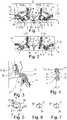
1 eine erste Ausführungsform eines Maxilla-Repositionsimplantates („double-ridge concept“), während des Einsetzens,2 das Maxilla-Repositionsimplantat mit seinen über Verbindungsstege verbundenen Platten der Basis und des Anschlussabschnitts bei schon entfernten Haltebügeln in einer zu1 vergleichbaren Ansicht,3 eine gedrehte Darstellung auf das eingesetzte Maxilla-Repositionsimplantatim Zustand aus 2 ,4 eine Vergrößerung desBereichs IV aus 2 mit eingesetzten Knochenschrauben,5 eine singuläre Darstellung der Seite eines einzigen Verbindungssteges aus3 ,6 und7 Querschnitte entlang der Linien VI und VII durchden Verbindungssteg aus 5 ,8 eine zweite Ausführungsform eines erfindungsgemäßen Maxilla-Repositionsimplantats („double-ridge concept with optimized path“), wobei die beiden Verbindungsstege, welche eine Platte der Basis und eine Platte des Anschlussabschnitts miteinander verbinden, voneinander beabstandet sind, also gespreizt sind, ergo einen rautenartigen Leerraum definieren,9 eine Darstellung des Maxilla-Repositionsimplantates aus 8 mit entfernten Haltebügeln,10 eine Seitendarstellung einer Hälfte des Maxilla-Repositionsimplantates mit entfernten Haltebügeln zum Zustand, wie in9 dargestellt,11 eine Vergrößerung des Bereichs aus9 mit eingesetzten Knochenschrauben,12 eine seitliche Darstellung eines der Verbindungsstege aus10 , und13 und 14 Querschnitte entlang den Linien XIII und XIV durch den jeweiligen Verbindungssteg aus12 .
1 a first embodiment of a maxilla repositioning implant (“double-ridge concept”) during insertion,2 the maxilla repositioning implant with its plates of the base and the connecting section connected via connecting webs with the retaining brackets already removed in one1 comparable view,3 a rotated representation of the inserted maxillary reduction implant in thestate 2 ,4 an enlargement ofarea IV 2 with inserted bone screws,5 a singular representation of the side of asingle tie bar 3 ,6 and7 Cross-sections along lines VI and VII through the connectingweb 5 ,8th a second embodiment of a maxilla repositioning implant according to the invention (“double-ridge concept with optimized path”), the two connecting webs, which connect a plate of the base and a plate of the connecting section, being spaced apart from one another, i.e. spread, ergo a rhombic empty space define,9 a representation of the maxillary reduction implant8th with removed brackets,10 a side view of one half of the maxillary reduction implant with the retaining brackets removed for the condition as in9 shown,11 an enlargement of the area9 with inserted bone screws,12 a side view of one of the connectingbridges 10 , and13 and14 Cross sections along the lines XIII and XIV through the respective connecting web12 .
Die Figuren sind lediglich schematischer Natur und dienen nur dem Verständnis der Erfindung. Gleiche Elemente sind mit denselben Bezugszeichen versehen.The figures are only of a schematic nature and serve only to understand the invention. Identical elements are provided with the same reference symbols.
Die erste Ausführungsform, die als „double-ridge concept“ beschreiben wird, betrifft ein Maxilla-Repositionsimplantat 1. Das Maxilla-Repositionsimplantat greift mit einer Basis 2 an einem schädelfesten Maxilla-Restabschnitt 3 an. Ein Anschlussabschnitt 4 des Maxilla-Repositionsimplantats 1 greift an einem Maxilla-Verlagerungsabschnitt 5 an. Der schädelfeste Maxilla-Restabschnitt 3 und der Maxilla-Verlagerungsabschnitt 5 sind Teile der Maxilla, also des Oberkiefers.The first embodiment, which is described as a “double-ridge concept”, relates to a maxillary reduction implant 1. The maxillary reduction implant engages with a
Der Anschlussabschnitt 4 ist von der Basis 2 des Maxilla-Repositionsimplantates 1 durch Verbindungsstege 6 beabstandet. Dabei greifen die Verbindungsstege 6, von denen es in dem vorliegenden Ausführungsbeispiel acht Stück gibt, an Platten 7 an.The connection section 4 is connected to the
Vier Platten 7 gehören dabei zur Basis 2 und vier Platten 7 gehören dabei zum Anschlussabschnitt 4. Es können pro Basis 2 oder pro Anschlussabschnitt 4 zwei, drei, vier, fünf, sechs, sieben oder sogar acht Platten 7 verwendet sein. Im vorliegenden Ausführungsbeispiel gibt es gleichviele Platten 7 in der Basis 2 dem Anschlussabschnitt 4, nämlich jeweils vier. Die Zahlen können jedoch unterschiedlich sein.Four
Es gibt auch Haltebügel 8, die die Platten 7 der Basis 2 miteinander verbinden oder die Platten 7 des Anschlussabschnitts 4 miteinander verbinden. Letztlich sind die Haltebügel 8 so eingesetzt, dass wenigstens immer zwei Platten 7 der Basis 2 oder des Anschlussabschnitts 4 miteinander verbunden sind. Darüber hinaus gibt es einen zentralen Haltebügel 8, der zusätzlich mit dem Bezugszeichen 9 gekennzeichnet ist und welcher die Verbindung der linken Hälfte des Maxilla Repositionsimplantats 1 mit der rechten Hälfte des Maxilla Repositionsimplantats 1 im Bereich des Anschlussabschnitts 4 sicherstellt. Die Anordnung des zentralen Haltebügels 9 als Teil des Anschlussabschnittes 4 ist von Vorteil, da dann das Bauteil unterhalb der Nase angeordnet werden kann, was einen relativ guten Tragekomfort und ein gutes Erscheinungsbild realisiert.There are also retaining
Zurückkommend zu den Verbindungsstegen 6 ist bedeutsam, dass in vorzugsweise allen Platten 7 jeweils zwei Schraubenlöcher 10 vorhanden sind. Die Schraubenlöcher 10 werden durch das Material der Platten 7 gebildet. Das Material der Platten 7 definiert dabei einen Rand 11 für das jeweilige Schraubenloch 10. Der Rand 11 ist als Wulst 12 ausgebildet. Es sollte beachtet werden, dass jede Platte 7 mehr als 45 Schraubenlöcher 10 besitzen soll.Coming back to the connecting
Im Übergangsbereich zwischen den Haltebügeln 8, also auch dem zentralen Haltebügel 9, zu den jeweiligen Platten 7 sind Ösen 13 vorgehalten. Die Ösen 13 weisen Längsachsen auf, die mit dem Bezugszeichen 14 versehen sind. Im Übergangsbereich zwischen den Haltebügeln 8 und den Platten 7 gibt es Sollbruchstellen 15. Diese sind exemplarisch an einem Haltebügel 8 dargestellt, gibt es jedoch an den meisten oder besser allen Haltebügeln 8.
Die Verbindungsstege 6 gehen immer von einer Platte 7 der Basis 2 ab, und stellen eine Verbindung mit dem Rand 11 einer Platte 7 des Anschlussabschnitts 4 sicher.The connecting
In dem Ausführungsbeispiel der
Diese Leerräume sind auch gut in
In
Die einzelnen Ränder 11 um die Schraubenlöcher 10 werden durch sie verbindende Füllbereiche 18 zur jeweiligen Platte 7 komplettiert. Es fällt auf, dass an wenigstens einer der Platten 7 des Anschlussabschnitts 4, jene die Ränder 11 zur Platte abschließenden Füllbereiche 18 einen Hohlraum 19 frei lassen.The individual edges 11 around the screw holes 10 are completed by filling
Dass die Ränder 11 auf ihrer Außenseite zylindrisch ausgebildet sind, zumindest von der Außenkontur her, aber auf ihrer Innenseite eine konkave an einen Schraubenkopf angepasste Form besitzen, ist der
In
Dass der Querschnitt des Verbindungssteges 6, vorzugsweise aller Verbindungsstege 6 über die Länge gesehen gleichbleibt und von Verbindungssteg 6 zu Verbindungssteg 6 nicht variiert, ist in Zusammenschau der
Die Ausführungsform, wie sie in den
BezugszeichenlisteReference List
- 11
- Maxilla RepositionsimplantatMaxilla reduction implant
- 22
- BasisBase
- 33
- schädelfester Maxilla Restabschnittskull-fixed maxilla residual section
- 44
- Anschlussabschnittconnector section
- 55
- Maxilla VerlagerungsabschnittMaxilla displacement section
- 66
- Verbindungsstegconnecting bar
- 77
- Platteplate
- 88th
- Haltebügelmounting bracket
- 99
- zentraler Haltebügelcentral bracket
- 1010
- Schraubenlochscrew hole
- 1111
- Randedge
- 1212
- Wulstbead
- 1313
- Öseeyelet
- 1414
- Längsachselongitudinal axis
- 1515
- Sollbruchstellepredetermined breaking point
- 1616
- Leerraumwhite space
- 1717
- Knochenschraubebone screw
- 1818
- Füllbereichfilling area
- 1919
- Hohlraumcavity
- 2020
- erstes Ende des Verbindungsstegesfirst end of the connecting bridge
- 2121
- zweites Ende des Verbindungsstegessecond end of the connecting bridge
- 2222
- gerader Abschnitt des Verbindungsstegesstraight section of the connecting bridge
- 2323
- Bogenabschnitt des VerbindungsstegsArch section of the connecting bridge
- 2424
- Hauptachsemain axis
- 2525
- Nebenachsesecondary axis
ZITATE ENTHALTEN IN DER BESCHREIBUNGQUOTES INCLUDED IN DESCRIPTION
Diese Liste der vom Anmelder aufgeführten Dokumente wurde automatisiert erzeugt und ist ausschließlich zur besseren Information des Lesers aufgenommen. Die Liste ist nicht Bestandteil der deutschen Patent- bzw. Gebrauchsmusteranmeldung. Das DPMA übernimmt keinerlei Haftung für etwaige Fehler oder Auslassungen.This list of documents cited by the applicant was generated automatically and is included solely for the better information of the reader. The list is not part of the German patent or utility model application. The DPMA assumes no liability for any errors or omissions.
Zitierte PatentliteraturPatent Literature Cited
- EP 2563244 B1 [0002, 0009]EP 2563244 B1 [0002, 0009]
- EP 2687168 B1 [0004]EP 2687168 B1 [0004]
- EP 2698122 B1 [0004]EP 2698122 B1 [0004]
- EP 2563242 B1 [0004]EP 2563242 B1 [0004]
- EP 3566663 A2 [0004]EP 3566663 A2 [0004]
- EP 3263050 B1 [0004]EP 3263050 B1 [0004]
- EP 2952145 B1 [0004]EP 2952145 B1 [0004]
- EP 2767246 A1 [0004]EP 2767246 A1 [0004]
- EP 2398411 B1 [0004]EP 2398411 B1 [0004]
- FR 2942125 B1 [0004]FR 2942125 B1 [0004]
- WO 2014090964 A2 [0004]WO 2014090964 A2 [0004]
- EP 2931143 A2 [0004]EP 2931143 A2 [0004]
- FR 2999071 A1 [0004]FR 2999071 A1 [0004]
- EP 2906129 B1 [0004]EP 2906129 B1 [0004]
- WO 2014043370 A1 [0004]WO 2014043370 A1 [0004]
Claims (10)
Translated fromGermanPriority Applications (7)
| Application Number | Priority Date | Filing Date | Title |
|---|---|---|---|
| DE102020134240.3ADE102020134240A1 (en) | 2020-12-18 | 2020-12-18 | Diamond-forming maxillary reduction implant |
| US18/246,965US20230363806A1 (en) | 2020-12-18 | 2021-12-13 | Rhombus-forming maxilla repositioning implant |
| CN202180056246.9ACN116018099A (en) | 2020-12-18 | 2021-12-13 | Diamond configured maxillary repositioning implant |
| AU2021404358AAU2021404358A1 (en) | 2020-12-18 | 2021-12-13 | Rhombus-forming maxilla repositioning implant |
| JP2023521917AJP2023553580A (en) | 2020-12-18 | 2021-12-13 | rhomboplasty maxillary repositioning implant |
| EP21836507.0AEP4203823A1 (en) | 2020-12-18 | 2021-12-13 | Rhombus-forming maxilla repositioning implant |
| PCT/EP2021/085559WO2022128961A1 (en) | 2020-12-18 | 2021-12-13 | Rhombus-forming maxilla repositioning implant |
Applications Claiming Priority (1)
| Application Number | Priority Date | Filing Date | Title |
|---|---|---|---|
| DE102020134240.3ADE102020134240A1 (en) | 2020-12-18 | 2020-12-18 | Diamond-forming maxillary reduction implant |
Publications (1)
| Publication Number | Publication Date |
|---|---|
| DE102020134240A1true DE102020134240A1 (en) | 2022-06-23 |
Family
ID=79259421
Family Applications (1)
| Application Number | Title | Priority Date | Filing Date |
|---|---|---|---|
| DE102020134240.3APendingDE102020134240A1 (en) | 2020-12-18 | 2020-12-18 | Diamond-forming maxillary reduction implant |
Country Status (7)
| Country | Link |
|---|---|
| US (1) | US20230363806A1 (en) |
| EP (1) | EP4203823A1 (en) |
| JP (1) | JP2023553580A (en) |
| CN (1) | CN116018099A (en) |
| AU (1) | AU2021404358A1 (en) |
| DE (1) | DE102020134240A1 (en) |
| WO (1) | WO2022128961A1 (en) |
Citations (8)
| Publication number | Priority date | Publication date | Assignee | Title |
|---|---|---|---|---|
| DE3839859A1 (en) | 1988-02-03 | 1989-08-17 | Bristol Myers Co | Bone plate |
| FR2942125B1 (en) | 2009-02-17 | 2012-02-17 | Obl | CUSTOM-MADE ASSEMBLY OF AT LEAST TWO OSTEOSYNTHESIS PLATES, THEMSELVES PREPARED TO MEASURE, AND METHOD FOR PLACING THE SAME |
| WO2014043370A1 (en) | 2012-09-12 | 2014-03-20 | Nextremity Solutions, Inc. | Bone shortening device and method |
| FR2999071A1 (en) | 2012-12-12 | 2014-06-13 | Obl | METHOD FOR REPOSITIONING BONE FRAGMENTS FOR BONE SURGERY BASED ON THE USE OF IMPLANTS AND CUSTOM GUIDES |
| EP2563242B1 (en) | 2010-04-29 | 2015-07-01 | Synthes GmbH | Orthognathic implant |
| EP2687168B1 (en) | 2010-04-29 | 2015-07-15 | Synthes GmbH | Orthognatic implant |
| EP2563244B1 (en) | 2010-04-29 | 2016-07-13 | Synthes GmbH | Orthognathic implant |
| US20190038414A1 (en) | 2017-08-03 | 2019-02-07 | Thomas S. Johnston, JR. | Orthognathic Implant Assembly and Method of Use |
Family Cites Families (5)
| Publication number | Priority date | Publication date | Assignee | Title |
|---|---|---|---|---|
| KR101788889B1 (en)* | 2009-12-11 | 2017-11-15 | 신세스 게엠바하 | Mandibular fixation plate |
| EP2701620A1 (en)* | 2011-04-26 | 2014-03-05 | Synthes GmbH | Hinged fixation devices for combined upper jaw correction |
| DE102015107484A1 (en)* | 2015-05-12 | 2016-11-17 | Karl Leibinger Medizintechnik Gmbh & Co. Kg | Orthogonal sawing and positioning implant |
| US10898332B2 (en)* | 2015-11-24 | 2021-01-26 | Ossdsign Ab | Bone implants and methods for correcting bone defects |
| US10932834B2 (en)* | 2015-12-03 | 2021-03-02 | Howard D. Stupak | Oblique three-dimensional plate |
- 2020
- 2020-12-18DEDE102020134240.3Apatent/DE102020134240A1/enactivePending
- 2021
- 2021-12-13EPEP21836507.0Apatent/EP4203823A1/enactivePending
- 2021-12-13USUS18/246,965patent/US20230363806A1/enactivePending
- 2021-12-13WOPCT/EP2021/085559patent/WO2022128961A1/ennot_activeCeased
- 2021-12-13AUAU2021404358Apatent/AU2021404358A1/enactivePending
- 2021-12-13CNCN202180056246.9Apatent/CN116018099A/enactivePending
- 2021-12-13JPJP2023521917Apatent/JP2023553580A/enactivePending
Patent Citations (17)
| Publication number | Priority date | Publication date | Assignee | Title |
|---|---|---|---|---|
| DE3839859A1 (en) | 1988-02-03 | 1989-08-17 | Bristol Myers Co | Bone plate |
| EP2767246A1 (en) | 2009-02-17 | 2014-08-20 | Obl | Ensemble sur mesure d'au moins deux plaques d'osteosynthese, elles-memes preparees sur mesure |
| FR2942125B1 (en) | 2009-02-17 | 2012-02-17 | Obl | CUSTOM-MADE ASSEMBLY OF AT LEAST TWO OSTEOSYNTHESIS PLATES, THEMSELVES PREPARED TO MEASURE, AND METHOD FOR PLACING THE SAME |
| EP2398411B1 (en) | 2009-02-17 | 2014-04-30 | Obl | Customised assembly including at least two osteosynthesis plates which are in turn customised |
| EP2952145B1 (en) | 2010-04-29 | 2017-09-20 | Synthes GmbH | Orthognathic implant |
| EP2563242B1 (en) | 2010-04-29 | 2015-07-01 | Synthes GmbH | Orthognathic implant |
| EP2687168B1 (en) | 2010-04-29 | 2015-07-15 | Synthes GmbH | Orthognatic implant |
| EP2563244B1 (en) | 2010-04-29 | 2016-07-13 | Synthes GmbH | Orthognathic implant |
| EP2698122B1 (en) | 2010-04-29 | 2017-07-05 | Synthes GmbH | Orthognathic implant |
| EP3263050B1 (en) | 2010-04-29 | 2019-05-22 | Synthes GmbH | Orthognathic implant |
| EP3566663A2 (en) | 2010-04-29 | 2019-11-13 | Synthes GmbH | Orthognathic implant |
| WO2014043370A1 (en) | 2012-09-12 | 2014-03-20 | Nextremity Solutions, Inc. | Bone shortening device and method |
| EP2906129B1 (en) | 2012-09-12 | 2018-04-25 | Nextremity Solutions, Inc. | Bone shortening device |
| WO2014090964A2 (en) | 2012-12-12 | 2014-06-19 | Obl S.A. | Implant and guide |
| FR2999071A1 (en) | 2012-12-12 | 2014-06-13 | Obl | METHOD FOR REPOSITIONING BONE FRAGMENTS FOR BONE SURGERY BASED ON THE USE OF IMPLANTS AND CUSTOM GUIDES |
| EP2931143A2 (en) | 2012-12-12 | 2015-10-21 | OBL (Société Anonyme) | Implant and guide |
| US20190038414A1 (en) | 2017-08-03 | 2019-02-07 | Thomas S. Johnston, JR. | Orthognathic Implant Assembly and Method of Use |
Also Published As
| Publication number | Publication date |
|---|---|
| US20230363806A1 (en) | 2023-11-16 |
| CN116018099A (en) | 2023-04-25 |
| AU2021404358A9 (en) | 2025-03-20 |
| JP2023553580A (en) | 2023-12-25 |
| EP4203823A1 (en) | 2023-07-05 |
| AU2021404358A1 (en) | 2023-05-11 |
| WO2022128961A1 (en) | 2022-06-23 |
Similar Documents
| Publication | Publication Date | Title |
|---|---|---|
| DE69838851T2 (en) | WIRBELSÄULENDISTRAKTIONSIMPLANTAT | |
| DE10248171A1 (en) | Implant for placement between vertebrae of the spine | |
| WO2012084896A1 (en) | Crestal implant and method for processing same | |
| WO2012076162A1 (en) | Device for bone regeneration and bone distraction | |
| CH668700A5 (en) | TOOTH ANCHOR PIN. | |
| EP2364124A1 (en) | Dental implant for insertion into a jawbone and for fastening a tooth replacement | |
| DE29615779U1 (en) | Implantable plate for maxillary facial surgery | |
| DE102014008449A1 (en) | Magnesium-based distraction membrane | |
| DE102013102411B4 (en) | ABUTMENT PACK FOR A PINE IMPLANT | |
| EP4203813A1 (en) | Maxilla repositioning implant comprising a retaining bracket | |
| DE3224112C2 (en) | Rod-shaped device for fastening an artificial tooth crown | |
| EP3651685B1 (en) | Bone augmentation piece, and kit consisting of a bone augmentation piece with an inserted (dental) implant | |
| EP2399540A2 (en) | Endosseous jaw implant for insertion in a cavity in a jaw bone and template for making the cavity in the jaw bone | |
| DE102020134240A1 (en) | Diamond-forming maxillary reduction implant | |
| DE102020134246A1 (en) | Fingerless Maxillary Reduction Implant | |
| EP4197466B1 (en) | Bone plate, surgical sets and reconstruction sets | |
| DE102007046879B4 (en) | Dental implant | |
| DE202014004751U1 (en) | implant | |
| DE202009018865U1 (en) | Block of bone - bone substitute material | |
| EP2811934B1 (en) | Implant, in particular dental implant | |
| EP3087954B1 (en) | Jaw bone transplant arrangement | |
| DE69829970T2 (en) | IMPLANT SYSTEM | |
| EP4099960B1 (en) | Intervertebral implant | |
| DE102021003024B4 (en) | One-piece dental implant | |
| DE20304367U1 (en) | Dental implant |
Legal Events
| Date | Code | Title | Description |
|---|---|---|---|
| R163 | Identified publications notified | ||
| R081 | Change of applicant/patentee | Owner name:KARL LEIBINGER ASSET MANAGEMENT GMBH & CO. KG, DE Free format text:FORMER OWNER: KARL LEIBINGER MEDIZINTECHNIK GMBH & CO. KG, 78570 MUEHLHEIM, DE |