DE102020132025A1 - Electromotive drive unit for motor vehicle applications - Google Patents
Electromotive drive unit for motor vehicle applicationsDownload PDFInfo
- Publication number
- DE102020132025A1 DE102020132025A1DE102020132025.6ADE102020132025ADE102020132025A1DE 102020132025 A1DE102020132025 A1DE 102020132025A1DE 102020132025 ADE102020132025 ADE 102020132025ADE 102020132025 A1DE102020132025 A1DE 102020132025A1
- Authority
- DE
- Germany
- Prior art keywords
- control element
- drive unit
- control
- sensor
- pin
- Prior art date
- Legal status (The legal status is an assumption and is not a legal conclusion. Google has not performed a legal analysis and makes no representation as to the accuracy of the status listed.)
- Pending
Links
- 230000005540biological transmissionEffects0.000claimsabstractdescription36
- 230000003993interactionEffects0.000claimsdescription2
- 230000008878couplingEffects0.000description6
- 238000010168coupling processMethods0.000description6
- 238000005859coupling reactionMethods0.000description6
- 238000000034methodMethods0.000description5
- 230000008569processEffects0.000description4
- 238000002347injectionMethods0.000description2
- 239000007924injectionSubstances0.000description2
- BUHVIAUBTBOHAG-FOYDDCNASA-N(2r,3r,4s,5r)-2-[6-[[2-(3,5-dimethoxyphenyl)-2-(2-methylphenyl)ethyl]amino]purin-9-yl]-5-(hydroxymethyl)oxolane-3,4-diolChemical compoundCOC1=CC(OC)=CC(C(CNC=2C=3N=CN(C=3N=CN=2)[C@H]2[C@@H]([C@H](O)[C@@H](CO)O2)O)C=2C(=CC=CC=2)C)=C1BUHVIAUBTBOHAG-FOYDDCNASA-N0.000description1
- 230000003213activating effectEffects0.000description1
- 230000004913activationEffects0.000description1
- 238000013475authorizationMethods0.000description1
- 230000008859changeEffects0.000description1
- 238000006073displacement reactionMethods0.000description1
- 230000009977dual effectEffects0.000description1
- 239000000383hazardous chemicalSubstances0.000description1
- 231100000206health hazardToxicity0.000description1
- 230000006872improvementEffects0.000description1
- 238000004519manufacturing processMethods0.000description1
Images


Classifications
- B—PERFORMING OPERATIONS; TRANSPORTING
- B60—VEHICLES IN GENERAL
- B60L—PROPULSION OF ELECTRICALLY-PROPELLED VEHICLES; SUPPLYING ELECTRIC POWER FOR AUXILIARY EQUIPMENT OF ELECTRICALLY-PROPELLED VEHICLES; ELECTRODYNAMIC BRAKE SYSTEMS FOR VEHICLES IN GENERAL; MAGNETIC SUSPENSION OR LEVITATION FOR VEHICLES; MONITORING OPERATING VARIABLES OF ELECTRICALLY-PROPELLED VEHICLES; ELECTRIC SAFETY DEVICES FOR ELECTRICALLY-PROPELLED VEHICLES
- B60L53/00—Methods of charging batteries, specially adapted for electric vehicles; Charging stations or on-board charging equipment therefor; Exchange of energy storage elements in electric vehicles
- B60L53/10—Methods of charging batteries, specially adapted for electric vehicles; Charging stations or on-board charging equipment therefor; Exchange of energy storage elements in electric vehicles characterised by the energy transfer between the charging station and the vehicle
- B60L53/14—Conductive energy transfer
- B60L53/16—Connectors, e.g. plugs or sockets, specially adapted for charging electric vehicles
- B—PERFORMING OPERATIONS; TRANSPORTING
- B60—VEHICLES IN GENERAL
- B60L—PROPULSION OF ELECTRICALLY-PROPELLED VEHICLES; SUPPLYING ELECTRIC POWER FOR AUXILIARY EQUIPMENT OF ELECTRICALLY-PROPELLED VEHICLES; ELECTRODYNAMIC BRAKE SYSTEMS FOR VEHICLES IN GENERAL; MAGNETIC SUSPENSION OR LEVITATION FOR VEHICLES; MONITORING OPERATING VARIABLES OF ELECTRICALLY-PROPELLED VEHICLES; ELECTRIC SAFETY DEVICES FOR ELECTRICALLY-PROPELLED VEHICLES
- B60L2270/00—Problem solutions or means not otherwise provided for
- B60L2270/30—Preventing theft during charging
- Y—GENERAL TAGGING OF NEW TECHNOLOGICAL DEVELOPMENTS; GENERAL TAGGING OF CROSS-SECTIONAL TECHNOLOGIES SPANNING OVER SEVERAL SECTIONS OF THE IPC; TECHNICAL SUBJECTS COVERED BY FORMER USPC CROSS-REFERENCE ART COLLECTIONS [XRACs] AND DIGESTS
- Y02—TECHNOLOGIES OR APPLICATIONS FOR MITIGATION OR ADAPTATION AGAINST CLIMATE CHANGE
- Y02T—CLIMATE CHANGE MITIGATION TECHNOLOGIES RELATED TO TRANSPORTATION
- Y02T10/00—Road transport of goods or passengers
- Y02T10/60—Other road transportation technologies with climate change mitigation effect
- Y02T10/70—Energy storage systems for electromobility, e.g. batteries
- Y—GENERAL TAGGING OF NEW TECHNOLOGICAL DEVELOPMENTS; GENERAL TAGGING OF CROSS-SECTIONAL TECHNOLOGIES SPANNING OVER SEVERAL SECTIONS OF THE IPC; TECHNICAL SUBJECTS COVERED BY FORMER USPC CROSS-REFERENCE ART COLLECTIONS [XRACs] AND DIGESTS
- Y02—TECHNOLOGIES OR APPLICATIONS FOR MITIGATION OR ADAPTATION AGAINST CLIMATE CHANGE
- Y02T—CLIMATE CHANGE MITIGATION TECHNOLOGIES RELATED TO TRANSPORTATION
- Y02T10/00—Road transport of goods or passengers
- Y02T10/60—Other road transportation technologies with climate change mitigation effect
- Y02T10/7072—Electromobility specific charging systems or methods for batteries, ultracapacitors, supercapacitors or double-layer capacitors
- Y—GENERAL TAGGING OF NEW TECHNOLOGICAL DEVELOPMENTS; GENERAL TAGGING OF CROSS-SECTIONAL TECHNOLOGIES SPANNING OVER SEVERAL SECTIONS OF THE IPC; TECHNICAL SUBJECTS COVERED BY FORMER USPC CROSS-REFERENCE ART COLLECTIONS [XRACs] AND DIGESTS
- Y02—TECHNOLOGIES OR APPLICATIONS FOR MITIGATION OR ADAPTATION AGAINST CLIMATE CHANGE
- Y02T—CLIMATE CHANGE MITIGATION TECHNOLOGIES RELATED TO TRANSPORTATION
- Y02T90/00—Enabling technologies or technologies with a potential or indirect contribution to GHG emissions mitigation
- Y02T90/10—Technologies relating to charging of electric vehicles
- Y02T90/14—Plug-in electric vehicles
Landscapes
- Engineering & Computer Science (AREA)
- Power Engineering (AREA)
- Transportation (AREA)
- Mechanical Engineering (AREA)
- Lock And Its Accessories (AREA)
Abstract
Translated fromGermanDescription
Translated fromGermanDie Erfindung betrifft eine elektromotorische Antriebseinheit für kraftfahrzeug-technische Anwendungen, insbesondere eine Verriegelungseinheit für eine elektrische Ladevorrichtung eines Kraftfahrzeuges, vorzugsweise eines Elektro- oder Hybrid-Kraftfahrzeuges, mit einem Elektromotor sowie zumindest einem nachgeschalteten Getriebeteil, ferner mit einem verfahrbaren Stellelement, und mit einem rotativ mit dem Getriebeteil gekoppelten Steuerelement zur Beaufschlagung eines Sensors.The invention relates to an electromotive drive unit for motor vehicle applications, in particular a locking unit for an electric charging device of a motor vehicle, preferably an electric or hybrid motor vehicle, with an electric motor and at least one downstream transmission part, also with a movable actuating element, and with a rotary with the transmission part coupled control for applying a sensor.
Akkumulatoren von Elektro- oder Hybrid-Kraftfahrzeugen müssen regelmäßig mit elektrischer Energie versorgt werden. Das geschieht regelmäßig unter Rückgriff auf eine Ladeinfrastruktur, zu welcher typischerweise Ladesäulen gehören. Für den Ladevorgang mit elektrischer Energie wird der Ladestecker der Ladesäule im Allgemeinen mit einer kraftfahrzeugseitigen Ladesteckdose gekoppelt und lösbar verriegelt. Die Verriegelung ist erforderlich, um beispielsweise Gesundheitsgefährdungen zu vermeiden, da an dieser Stelle im Allgemeinen mit Hochspannung gearbeitet wird. Außerdem stellt die Verriegelung sicher, dass ausschließlich zuvor identifizierte Benutzer die von der Ladesäule zur Verfügung gestellte Energie auch rechtmäßig beziehen und Missbrauch verhindert wird. Zu diesem Zweck findet meistens vor einem solchen Ladevorgang eine Identifizierung des Bedieners und eine Berechtigungsprüfung mithilfe eines Identifikationssignals statt, wie dies grundsätzlich in der
Bei dem Stellelement handelt es sich in der Regel um ein Riegelelement oder einen Verriegelungszapfen, wie dies die
Im gattungsbildenden Stand der Technik nach der
Der Stand der Technik hat sich grundsätzlich bewährt, bietet jedoch noch Raum für Verbesserungen. Tatsächlich beobachtet man bei solchen elektromotorischen Antriebseinheiten bzw. Verriegelungseinheiten Ungenauigkeiten bei der Auslösung und Ansteuerung des Sensors. Als Folge hiervon ist auch die Auflösung begrenzt. D. h., der Sensor gibt nur ungenau Auskunft darüber, welche Position letztendlich das Stellelement eingenommen hat. Die exakte Positionsbestimmung des Stellelementes bzw. Riegelelementes ist aber für eine einwandfreie Funktionsweise unerlässlich.The state of the art has proven itself in principle, but still offers room for improvement. In fact, with such electromotive drive units or locking units, inaccuracies are observed in the triggering and activation of the sensor. As a result, the resolution is also limited. In other words, the sensor only provides imprecise information about the position that the control element has finally assumed. However, the exact position determination of the actuating element or locking element is essential for proper functioning.
Das lässt sich darauf zurückführen, dass der Sensor bzw. Mikroschalter mithilfe des Betätigungsnockens in axialer Richtung beaufschlagt wird und zugleich in dieser axialen Richtung Getriebespiel insbesondere bei einer Richtungsumkehr beobachtet wird. Dieses Getriebespiel führt zu Toleranzen bei der Sensorbeaufschlagung, die wiederum die Auflösung verringern. Hier will die Erfindung insgesamt Abhilfe schaffen.This can be attributed to the fact that the sensor or microswitch is acted upon in the axial direction with the aid of the actuating cam and at the same time gear play is observed in this axial direction, in particular when there is a reversal of direction. This gear play leads to tolerances in the sensor loading, which in turn reduce the resolution. This is where the invention aims to remedy the situation overall.
Der Erfindung liegt das technische Problem zugrunde, eine derartige elektromotorische Antriebseinheit so weiterzuentwickeln, dass die Genauigkeit der Sensorabfrage insgesamt gesteigert ist.The invention is based on the technical problem of further developing such an electromotive drive unit in such a way that the overall accuracy of the sensor query is increased.
Zur Lösung dieser technischen Problemstellung schlägt die Erfindung bei einer gattungsgemäßen elektromotorischen Antriebseinheit für kraftfahrzeug-technische Anwendungen vor, dass das Getriebeteil und das Steuerelement axial entkoppelt jedoch radial drehfest miteinander verbunden sind.To solve this technical problem, the invention proposes in a generic electric motor drive unit for motor vehicle applications that the transmission part and the control element are axially decoupled but radially connected to one another in a rotationally fixed manner.
D. h., durch die axiale Entkopplung des Getriebeteils und des Steuerelementes werden zunächst einmal etwaige Axialbewegungen des Getriebeteils nicht auf das Steuerelement übertragen. Solche Axialbewegungen des Getriebeteils werden oftmals bei einem Richtungswechsel des Elektromotors inklusive Getriebeteil beobachtet. Die dadurch entstehende Axialbewegung wird nun erfindungsgemäß nicht (mehr) auf das Steuerelement übertragen, weil hierfür die axiale Entkopplung zwischen dem Getriebeteil und dem Steuerelement sorgt. Die gleichwohl radial drehfeste Kopplung zwischen dem Getriebeteil und dem Steuerelement wird nun zur Beaufschlagung des Sensors genutzt. Da an dieser Stelle das Getriebeteil und das Steuerelement radial drehfest miteinander gekoppelt sind, folglich praktisch ohne Spiel ineinandergreifen, folgt das Steuerelement jeder rotativen Bewegung des Getriebeteils, sodass der mithilfe des Steuerelementes beaufschlagte Sensor die Rotationsbewegungen des Getriebeteils spielfrei oder nahezu spielfrei abbildet. Da die Rotationsbewegungen des Getriebeteils unmittelbar mit Stellbewegungen des Stellelementes bzw. Riegelelementes einhergehen, kann hierdurch mithilfe des Sensors die jeweilige Position des Stellelementes bzw. Riegelelementes mit hoher Genauigkeit erfasst und beispielsweise von einer Steuereinheit abgefragt werden.That is, due to the axial decoupling of the gear part and the control element, any axial movements of the gear part are not initially transmitted to the control element. Such axial movements of the gear part are often observed when the electric motor, including the gear part, changes direction. According to the invention, the resulting axial movement is no longer transmitted to the control element because the axial decoupling between the transmission part and the control element ensures this. The nevertheless radially non-rotatable coupling between the transmission part and the control element is now used to act on the sensor. There on At this point, the gear part and the control element are coupled to one another in a radially non-rotatable manner, meaning that they mesh with one another with practically no play, the control element follows every rotational movement of the gear part, so that the sensor acted upon by the control element depicts the rotational movements of the gear part with no or almost no play. Since the rotational movements of the gear part are directly associated with actuating movements of the actuating element or locking element, the respective position of the actuating element or locking element can be detected with high accuracy using the sensor and queried, for example, by a control unit.
Nach weiterer vorteilhafter Ausgestaltung verfügt das Steuerelement zur axialen Entkopplung von dem Getriebeteil über einen Zapfen, welcher mit Spiel in eine zugehörige Ausnehmung des Getriebeteils eingreift. D. h., die Wechselwirkung zwischen dem Zapfen am Steuerelement und der ihn aufnehmenden Ausnehmung des Getriebeteils ist so getroffen, dass der fragliche Zapfen innerhalb der Ausnehmung ein axiales Spiel aufweist, allerdings in der Ausnehmung radial spielfrei aufgenommen wird. Grundsätzlich kann auch umgekehrt vorgegangen werden. In diesem Fall ist das Steuerelement mit der fraglichen Ausnehmung ausgerüstet, wohingegen das Getriebeteil den Zapfen aufweist.According to a further advantageous embodiment, the control element has a pin for axial decoupling from the gear part, which engages with play in an associated recess of the gear part. That is, the interaction between the pin on the control element and the recess of the transmission part that accommodates it is such that the pin in question has axial play within the recess, but is received in the recess without radial play. In principle, the reverse procedure can also be used. In this case the control element is equipped with the recess in question, whereas the gear part has the pin.
In diesem Zusammenhang hat es sich als günstig erwiesen, wenn der Zapfen kopfseitig an einem exzentrischen Ausleger des Steuerelementes angeordnet ist. Bei diesem exzentrischen Ausleger handelt es sich typischerweise um einen solchen, welcher zur Wechselwirkung mit dem Stellelement eingerichtet ist. Dazu kann der exzentrische Ausleger als Bestandteil des Steuerelementes in eine entsprechende U-förmige Aufnahme des Stellelementes bzw. Riegelelementes eingreifen.In this context, it has proven to be advantageous if the pin is arranged at the head end on an eccentric arm of the control element. This eccentric cantilever is typically one that is set up to interact with the actuating element. For this purpose, the eccentric arm, as part of the control element, can engage in a corresponding U-shaped receptacle of the actuating element or locking element.
Auf diese Weise werden Rotationen des Getriebeteils auf das ebenfalls rotierende Steuerelement übertragen. Durch die drehfeste Kopplung zwischen dem Getriebeelement und dem Steuerelement folgt das Steuerelement dem Getriebeteil (in der Rotationsrichtung) unmittelbar und spielfrei oder nahezu spielfrei, während gleichzeitig durch die erfindungsgemäß realisierte axiale Entkopplung ein Axialspiel zwischen dem Getriebeteil und dem Steuerelement zugelassen wird. Das rotierende Steuerelement greift nun mit seinem exzentrischen Ausleger in die U-förmige Aufnahme des Stellelementes ein, welches folgerichtig hierdurch Linearbewegungen vollführen kann. Da das Steuerelement den Sensor beaufschlagt, gibt dieser unmittelbar Auskunft über die Position des Stellelementes bzw. Riegelelementes, und zwar mit einer im Vergleich zum bisherigen Stand der Technik deutlich verbesserten Auflösung.In this way, rotations of the transmission part are transferred to the control element, which is also rotating. Due to the non-rotatable coupling between the gear element and the control element, the control element follows the gear part (in the direction of rotation) directly and with no or almost no play, while at the same time an axial play between the gear part and the control element is permitted due to the axial decoupling realized according to the invention. The rotating control element now engages with its eccentric arm in the U-shaped receptacle of the control element, which can consequently perform linear movements as a result. Since the control element acts on the sensor, this provides direct information about the position of the actuating element or locking element, with a resolution that is significantly improved compared to the prior art.
Der Zapfen ist in der Regel als Montagezapfen ausgebildet. Auf diese Weise können das Steuerelement und das Getriebeteil durch eine axiale Steckverbindung miteinander gekoppelt werden. D. h., das Steuerelement und das Getriebeteil lassen sich werkzeuglos miteinander verbinden, indem die angesprochene Steckverbindung zwischen beiden Elementen hergestellt wird. Da hierbei der Zapfen bzw. Montagezapfen am Steuerelement in die Ausnehmung des Getriebeteils eingreift, werden am Ende der Montage beide Elemente unverlierbar miteinander gekoppelt.The pin is usually designed as a mounting pin. In this way, the control element and the gear part can be coupled to one another by means of an axial plug-in connection. That is to say, the control element and the transmission part can be connected to one another without the use of tools by making the plug-in connection mentioned between the two elements. Since the pin or assembly pin on the control element engages in the recess of the gear part, both elements are captively coupled to one another at the end of assembly.
Auf diese Weise bilden das Steuerelement und das Getriebeteil vorteilhaft eine vormontierte Baueinheit. Diese Baueinheit kann zusammengenommen gegebenenfalls inklusive des Stellelementes in ein die elektromotorische Antriebseinheit Insgesamt aufnehmendes Gehäuse eingesetzt werden. Dadurch wird die Montage enorm erleichtert, zumal dieser Vorgang insgesamt werkzeuglos erfolgen kann und ohne dass zusätzliche Verbindungsmittel wie Schrauben etc. zur gegenseitigen Kopplung erforderlich wären.In this way, the control element and the gear part advantageously form a preassembled structural unit. Taken together, this structural unit, optionally including the actuating element, can be inserted into a housing that accommodates the electromotive drive unit as a whole. This simplifies assembly enormously, especially since this process can be carried out without tools and without the need for additional connecting means such as screws etc. for mutual coupling.
Das Steuerelement selbst ist nun in dem fraglichen Gehäuse drehbar sowie axial geführt gelagert. D. h., das Steuerelement selbst vollführt aufgrund seiner axialen Führung keine Axialbewegungen, sodass der mithilfe des Steuerelementes angesteuerte Sensor einwandfreie Signale mit großer Auflösung erzeugt. Dabei ist im Detail zur Axialführung des Steuerelementes im Allgemeinen ein Führungszapfen vorgesehen, welcher zwischen Führungswangen des Steuerelementes eingreift. Dieser Führungszapfen kann vorteilhaft an das Gehäuse angeschlossen bzw. angeformt sein. Tatsächlich ist das Gehäuse regelmäßig aus Kunststoff hergestellt bzw. als Kunststoffspritzgussbauteil ausgeführt, sodass der fragliche Führungszapfen unmittelbar bei der Herstellung des Gehäuses in diesem definiert werden kann.The control itself can now be rotated and guided axially in the housing in question. That is to say, the control element itself does not perform any axial movements due to its axial guidance, so that the sensor controlled using the control element generates perfect signals with a high resolution. In detail, a guide pin is generally provided for the axial guidance of the control element, which engages between the guide cheeks of the control element. This guide pin can advantageously be connected to or formed on the housing. In fact, the housing is regularly made of plastic or designed as a plastic injection-molded component, so that the guide pin in question can be defined in the housing directly during manufacture of the latter.
Für die drehbare Lagerung des Steuerelementes sorgt demgegenüber ein Achsfortsatz des Getriebeteils. D. h., bei der Vereinigung des Getriebeteils mit dem Steuerelement wird das Steuerelement mit einer Drehaufnahme auf den fraglichen Achsfortsatz des Getriebeteils aufgesteckt. Zugleich fährt bei der realisierten Steckverbindung der als Montagezapfen ausgebildete Zapfen kopfseitig des exzentrischen Auslegers an dem Steuerelement in die Ausnehmung des Getriebeteils und greift in diese ein. Als Folge der realisierten axialen Steckverbindung wird die zuvor bereits angesprochene vormontierte Baueinheit aus dem Steuerelement und dem Getriebeteil zur Verfügung gestellt. Zusätzlich kann dann auch noch das Stellelement hiermit vereinigt werden, indem das Stellelement mit seiner U-förmigen Aufnahme auf den exzentrischen Ausleger aufgesteckt wird bzw. der exzentrische Ausleger in die U-förmige Aufnahme eingreift.In contrast, an axle extension of the transmission part provides for the rotatable mounting of the control element. That is, when the transmission part is combined with the control element, the control element is plugged onto the axle extension in question of the transmission part with a rotary receptacle. At the same time, in the realized plug-in connection, the spigot designed as a mounting spigot moves on the head side of the eccentric arm on the control element into the recess of the gear part and engages in it. As a result of the realized axial plug-in connection, the previously mentioned preassembled structural unit made up of the control element and the transmission part is made available. Additionally the actuating element can then also be combined with this, in that the actuating element is fitted with its U-shaped receptacle onto the eccentric arm or the eccentric arm engages in the U-shaped receptacle.
D. h., das Steuerelement ist drehbar auf dem Achsfortsatz des Getriebeteils gelagert, welches seinerseits eine drehbare Lagerung innerhalb des Gehäuses erfährt. Hierzu sind ein oder mehrere zugehörige Aufnahmen bzw. Drehaufnahmen im Gehäuse vorgesehen, mit deren Hilfe das Getriebeteil einerseits mit dem bereits angesprochenen Achsfortsatz und andererseits einem gegenüberliegenden Achsfortsatz gelagert wird.That is, the control element is rotatably mounted on the axial extension of the transmission part, which in turn is rotatably mounted within the housing. For this purpose, one or more associated receptacles or rotary receptacles are provided in the housing, with the help of which the transmission part is mounted on the one hand with the already mentioned axial extension and on the other hand with an opposite axial extension.
Die Ansteuerung des Sensors wird nun im Detail so vorgenommen, dass das Steuerelement mit einer Steuerscheibe zur axialen Beaufschlagung des Sensors ausgerüstet ist. Dazu verfügt die Steuerscheibe vorteilhaft über eine Steuerkontur für den Sensor. Die Steuerkontur ist in der Regel so ausgebildet, dass sie Axialbereiche unterschiedlicher Länge aufweist. Da es sich bei dem Sensor vorteilhaft um einen Schalter bzw. Mikroschalter mit einem Schaltnocken handelt, kann nun der an den Axialbereichen unterschiedlicher Länge entlanggleitende Schaltnocken die genaue Position der Steuerscheibe erfassen. Da die Steuerscheibe drehfest mit dem Getriebeteil und rotativ spielfrei oder nahezu spielfrei verbunden ist und gleiches für die Kopplung zwischen dem exzentrischen Ausleger und der U-förmigen Aufnahme des Stellelementes gilt, kann anhand von Signalen des Sensors respektive Schalters unmittelbar auf die Position des Stellelementes rückgeschlossen werden. Es wird also eine besonders hohe Auflösung mit großer Genauigkeit für die Position des Stellelementes zur Verfügung gestellt.The control of the sensor is now carried out in detail in such a way that the control element is equipped with a control disk for the axial loading of the sensor. For this purpose, the control disc advantageously has a control contour for the sensor. The control contour is usually designed in such a way that it has axial regions of different lengths. Since the sensor is advantageously a switch or microswitch with a switching cam, the switching cam sliding along the axial regions of different lengths can now detect the exact position of the control disk. Since the control disc is rotatably connected to the gear part and rotationally free of play or almost free of play and the same applies to the coupling between the eccentric arm and the U-shaped receptacle of the actuating element, the position of the actuating element can be directly deduced from signals from the sensor or switch . A particularly high resolution with great accuracy is therefore made available for the position of the actuating element.
Hierzu trägt ergänzend der Umstand bei, dass die fragliche Steuerkontur an der Steuerscheibe am radial äußeren Rand vorgesehen ist, sodass ein großer Verstellweg der Axialbereiche unterschiedlicher Länge zur Beaufschlagung des Sensors bzw. Schalters zur Verfügung steht und sich dadurch die hohe Auflösung erklärt.The fact that the control contour in question is provided on the control disc at the radially outer edge also contributes to this, so that a large adjustment path of the axial areas of different lengths is available for loading the sensor or switch, which explains the high resolution.
Durch die Möglichkeit, das Getriebeteil und das Steuerelement im Sinne der Steckverbindung miteinander zu koppeln, welche durch den in die Ausnehmung eingreifenden Zapfen darüber hinaus mit einer lösbaren Rastung ausgerüstet sind, lässt sich das Steuerelement grundsätzlich austauschen und je nach Anwendungsfall ein geeignetes Steuerelement mit dem Getriebeteil koppeln. Hierzu trägt zusätzlich der Umstand bei, dass typischerweise sowohl das Getriebeteil als auch das Steuerelement jeweils als Kunststoffspritzgussteile ausgebildet sind. Dadurch kann das Steuerelement und ebenso das Getriebeteil besonders einfach und kostengünstig hergestellt werden. Auch das Stellelement ist in der Regel als Kunststoffspritzgussteil ausgeführt. Eine besonders kompakte Bauform wird dann noch dadurch erreicht, dass eine der beiden Führungswangen des Steuerelementes zugleich die Funktionsweise der Steuerscheibe übernimmt. D. h., der vorzugsweise an das Gehäuse angeformte Führungszapfen zur Axialführung des Steuerelementes greift typischerweise zwischen eine Führungswange und die Steuerscheibe ein, und zwar regelmäßig spielfrei, damit der mithilfe der Steuerscheibe angesteuerte Sensor das Sensorsignal gewünschter Auflösung abgibt. Dieses Sensorsignal wird in der Regel von einer Steuereinheit ausgewertet und in entsprechende Verfahrwege des Stellelementes umgesetzt.Due to the possibility of coupling the gear part and the control element to each other in the sense of the plug-in connection, which are also equipped with a releasable detent due to the pin engaging in the recess, the control element can basically be exchanged and, depending on the application, a suitable control element with the gear part couple. The fact that both the transmission part and the control element are typically designed as plastic injection-molded parts also contributes to this. As a result, the control element and also the gear part can be manufactured particularly easily and inexpensively. The actuating element is also usually designed as a plastic injection molded part. A particularly compact design is then achieved in that one of the two guide cheeks of the control element also takes over the function of the control disk. That is, the guide pin preferably formed on the housing for axial guidance of the control element typically engages between a guide cheek and the control disk, usually without play, so that the sensor controlled using the control disk emits the sensor signal with the desired resolution. As a rule, this sensor signal is evaluated by a control unit and converted into corresponding displacement paths of the actuating element.
Als Folge hiervon wird eine gegenüber dem Stand der Technik deutlich verbesserte Auflösung bei der Erfassung des Verfahrweges des Stellelementes zur Verfügung gestellt. Das ist insbesondere für Anwendungen als Verriegelungseinheit für die elektrische Ladevorrichtung von besonderer Bedeutung, weil über die Position des Stellelementes bzw. Riegelelementes in diesem Fall unter anderem der sichere Halt des Ladesteckers in der Ladesteckdose überprüft wird, sodass erst dann der Ladevorgang sicher gestartet werden kann. Es handelt sich also um eine in Anbetracht der in diesem Bereich übertragenen Hochspannung relevanten Sicherheitsaspekt. Hierin sind die wesentlichen Vorteile zu sehen.As a result of this, a significantly improved resolution compared to the prior art is made available when detecting the travel path of the actuating element. This is of particular importance for applications as a locking unit for the electric charging device, because in this case the position of the actuating element or locking element is used to check, among other things, that the charging plug is securely held in the charging socket, so that the charging process can only then be started safely. This is therefore a relevant safety aspect in view of the high voltage transmitted in this area. This is where the main advantages can be seen.
Im Folgenden wird die Erfindung anhand einer lediglich ein Ausführungsbeispiel darstellenden Zeichnung näher erläutert; es zeigen:
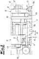
1 die elektromotorische Antriebseinheit in einer perspektivischen Übersicht,2 das Getriebeteil und das Steuerelement im Zuge ihrer Vormontage,3 das Getriebeteil und das Steuerelement in eingebautem Zustand in einer Detailansicht und4 das Steuerelement in einer Perspektive.
1 the electromotive drive unit in a perspective overview,2 the gear part and the control element in the course of their pre-assembly,3 the transmission part and the control element in installed condition in a detailed view and4 the control in a perspective.
In den Figuren ist eine elektromotorische Antriebseinheit für kraftfahrzeug-technische Anwendungen dargestellt. Im Rahmen des nachfolgend noch näher zu beschreibenden Ausführungsbeispiels wird die elektromotorische Antriebseinheit genutzt, um einen Ladestecker einer Ladesäuleninfrastruktur mit einer kraftfahrzeugseitigen Ladesteckdose lösbar zu verriegeln. Dazu verfügt die elektromotorische Antriebseinheit über ein Stellelement 1, welches in diesem Fall als Riegelelement 1 bzw. Verriegelungselement oder Riegelzapfen ausgebildet ist. Details des Aufbaus eines zugehörigen Lademoduls mit der Ladesteckdose der elektrischen Ladevorrichtung und der Verriegelung des Ladesteckers in der Ladesteckdose sind in der einleitend bereits in Bezug genommenen
D. h., die elektromotorische Antriebseinheit ist im Rahmen des Ausführungsbeispiels als Verriegelungseinheit für die fragliche elektrische Ladevorrichtung des nicht näher dargestellten Kraftfahrzeuges ausgebildet. Es handelt sich also um einen Verriegelungsaktuator, wie er in der zuvor als Referenz genannten Veröffentlichung im Detail beschrieben wird. Grundsätzlich kann die elektromotorische Antriebseinheit aber auch für anderweitige Zwecke genutzt werden. Entscheidend ist der Umstand, dass das Stellelement 1 bzw. das Verriegelungselement oder Riegelelement 1 die in der
Die elektromotorische Antriebseinheit bzw. Verriegelungseinheit nach der Darstellung verfügt in ihrem grundsätzlichen Aufbau zunächst einmal über einen Elektromotor 2 sowie zumindest ein nachgeschaltetes Getriebeteil 3, 4. Anhand des Ausführungsbeispiels in der
Von besonderer Bedeutung ist dann noch ein rotativ mit dem Getriebeteil 4 gekoppeltes Steuerelement 5. Das Steuerelement 5 ist in der
Der Sensor 6 wird seinerseits von einer nicht näher dargestellten Steuereinheit abgefragt, welche die Signale des Sensors 6 auswertet. Aus den Signalen des Sensors 6 kann nun auf die Stellbewegung des Stellelementes 1 in der in
Zu diesem Zweck sind zunächst einmal und erfindungsgemäß das Getriebeteil 4 und das Steuerelement 5 axial entkoppelt jedoch radial drehfest miteinander verbunden. Diese spezielle Auslegung kann man anhand der
Dazu ist der besagte Zapfen 7 des Steuerelementes 5 zunächst einmal kopfseitig eines exzentrischen Auslegers 7a angeordnet. Der exzentrische Ausleger 7a ist seinerseits zur Wechselwirkung mit dem Stellelement 1 eingerichtet. Dazu greift der exzentrische Ausleger 7a in eine U-förmiger Aufnahme 1 a des Stellelementes 1 ein, wie die vergrößerte Darstellung in der
Das Steuerelement 5 ist darüber hinaus mit einer nachfolgend noch näher zu betrachtenden Steuerscheibe 9 und zusätzlich einer Führungswange 10 ausgerüstet. Außerdem verfügt das Steuerelement 5 noch über eine Aufnahme bzw. Drehaufnahme 11.The
Mithilfe der Aufnahme bzw. Drehaufnahme 11 wird das Steuerelement 5 bei der Vereinigung mit dem Getriebeteil 4 auf einen Achsfortsatz 12 des Getriebeteils 4 aufgesteckt. Neben dem Achsfortsatz 12 verfügt das Getriebeteil 4 zusätzlich noch über einen weiteren und gegenüberliegenden Achsfortsatz 13. Mithilfe der beiden Achsfortsätze 12, 13 ist das Getriebeteil 4 in zugehörigen und in der
Der Zapfen 7 kopfseitig des exzentrischen Auslegers 7a am Steuerelement 5 ist als Montagezapfen ausgebildet, sodass das Steuerelement 5 und das Getriebeteil 4 durch eine in der
Das Steuerelement 5 ist drehbar sowie axial geführt im Gehäuse 14 gelagert. Die drehbare Lagerung des Steuerelementes 5 wird dabei von dem Achsfortsatz 12 des Getriebeteils 4 übernommen, welcher in die zugehörige Aufnahme bzw. Drehaufnahme 11 des Steuerelementes 5 eingreift. Für die Axialführung des Steuerelementes 5 sorgt nun ein zusätzlicher Führungszapfen 15. Dieser Führungszapfen 15 ist an das Gehäuse 14 angeschlossen, nach dem Ausführungsbeispiel an das Gehäuse 14 angeformt. Zu diesem Zweck greift der Führungszapfen 15 zwischen einerseits die Führungswange 10 und andererseits die Steuerscheibe 9 ein, sodass die Steuerscheibe 9 eine Doppelfunktion übernimmt, nämlich einerseits zur Ansteuerung des Sensors 6 und andererseits als gleichsam zweite Führungswange i. V. m. der Führungswange 10. Das wird insbesondere anhand der
Die
Die Steuerscheibe 9 ist nun mit einer insbesondere in der
Der Sensor bzw. Schalter 6 findet sich in einer Ecke des Gehäuses 14. Dadurch ist der Sensor 6 radial mit größtmöglichem Abstand von der durch die Aufnahme bzw. Drehaufnahme 11 definierten Achse des Steuerelementes 5 angeordnet. Demzufolge findet sich die Steuerkontur 16 auch radial am äußeren Rand der Steuerscheibe 9, sodass aufgrund des durch den großen Umfang beobachteten langen Stellweges der Steuerkontur 16 eine hohe Auflösung und große Genauigkeit des Signals des Sensors 6 erreicht wird.The sensor or switch 6 is located in a corner of the
BezugszeichenlisteReference List
- 11
- Stellelement / RiegelelementActuating element / locking element
- 1a1a
- Aufnahmerecording
- 22
- Elektromotorelectric motor
- 3, 43, 4
- Getriebeteilgear part
- 55
- Steuerelementcontrol
- 66
- Sensorsensor
- 77
- Zapfencones
- 7a7a
- Auslegerboom
- 88th
- Ausnehmungrecess
- 99
- Steuerscheibecontrol disc
- 1010
- Führungswangeguide rail
- 1111
- Aufnahme bzw. DrehaufnahmeRecording or shooting
- 12, 1312, 13
- Achsfortsatzaxial extension
- 1414
- GehäuseHousing
- 1515
- Führungszapfenpilot
- 1616
- Steuerkonturcontrol contour
- AA
- Axialrichtungaxial direction
- RR
- Radialrichtungradial direction
- Uu
- Umfangsrichtungcircumferential direction
- SS
- SpielGame
ZITATE ENTHALTEN IN DER BESCHREIBUNGQUOTES INCLUDED IN DESCRIPTION
Diese Liste der vom Anmelder aufgeführten Dokumente wurde automatisiert erzeugt und ist ausschließlich zur besseren Information des Lesers aufgenommen. Die Liste ist nicht Bestandteil der deutschen Patent- bzw. Gebrauchsmusteranmeldung. Das DPMA übernimmt keinerlei Haftung für etwaige Fehler oder Auslassungen.This list of the documents cited by the applicant was generated automatically and is included solely for the better information of the reader. The list is not part of the German patent or utility model application. The DPMA assumes no liability for any errors or omissions.
Zitierte PatentliteraturPatent Literature Cited
- WO 2010/149426 A1 [0002]WO 2010/149426 A1 [0002]
- DE 102018114205 A1 [0003, 0023]DE 102018114205 A1 [0003, 0023]
- CN 202695855 U [0004]CN 202695855 U [0004]
Claims (10)
Translated fromGermanPriority Applications (2)
| Application Number | Priority Date | Filing Date | Title |
|---|---|---|---|
| DE102020132025.6ADE102020132025A1 (en) | 2020-12-02 | 2020-12-02 | Electromotive drive unit for motor vehicle applications |
| PCT/DE2021/100960WO2022117154A1 (en) | 2020-12-02 | 2021-12-02 | Electromotive drive unit for motor vehicle applications |
Applications Claiming Priority (1)
| Application Number | Priority Date | Filing Date | Title |
|---|---|---|---|
| DE102020132025.6ADE102020132025A1 (en) | 2020-12-02 | 2020-12-02 | Electromotive drive unit for motor vehicle applications |
Publications (1)
| Publication Number | Publication Date |
|---|---|
| DE102020132025A1true DE102020132025A1 (en) | 2022-06-02 |
Family
ID=78916693
Family Applications (1)
| Application Number | Title | Priority Date | Filing Date |
|---|---|---|---|
| DE102020132025.6APendingDE102020132025A1 (en) | 2020-12-02 | 2020-12-02 | Electromotive drive unit for motor vehicle applications |
Country Status (2)
| Country | Link |
|---|---|
| DE (1) | DE102020132025A1 (en) |
| WO (1) | WO2022117154A1 (en) |
Citations (9)
| Publication number | Priority date | Publication date | Assignee | Title |
|---|---|---|---|---|
| WO2010149426A1 (en) | 2009-06-22 | 2010-12-29 | Rwe Ag | Charging cable plug for electric vehicles |
| DE102011050783A1 (en) | 2011-01-27 | 2012-08-02 | Huf Hülsbeck & Fürst Gmbh & Co. Kg | Locking device, in particular for a plug |
| US20120234061A1 (en) | 2011-03-18 | 2012-09-20 | Kabushiki Kaisha Tokai Rika Denki Seisakusho | Power plug locking device |
| CN202695855U (en) | 2012-06-11 | 2013-01-23 | 南京康尼科技实业有限公司 | Level locking device for charging plug and socket of electric automobile |
| US20130078840A1 (en) | 2011-09-28 | 2013-03-28 | Kabushiki Kaisha Tokai Rika Denki Seisakusho | Power plug locking device |
| DE202013009554U1 (en) | 2013-10-28 | 2015-01-29 | Kiekert Aktiengesellschaft | Electrical plug connection |
| DE102017130658A1 (en) | 2017-12-20 | 2019-06-27 | Kiekert Ag | Locking device for an electric charging device |
| DE102018109661A1 (en) | 2018-04-23 | 2019-10-24 | Kiekert Ag | locking device |
| DE102018114205A1 (en) | 2018-06-14 | 2019-12-19 | Kiekert Ag | LOCKING DEVICE FOR AN ELECTRIC CHARGING DEVICE OF A MOTOR VEHICLE |
- 2020
- 2020-12-02DEDE102020132025.6Apatent/DE102020132025A1/enactivePending
- 2021
- 2021-12-02WOPCT/DE2021/100960patent/WO2022117154A1/ennot_activeCeased
Patent Citations (9)
| Publication number | Priority date | Publication date | Assignee | Title |
|---|---|---|---|---|
| WO2010149426A1 (en) | 2009-06-22 | 2010-12-29 | Rwe Ag | Charging cable plug for electric vehicles |
| DE102011050783A1 (en) | 2011-01-27 | 2012-08-02 | Huf Hülsbeck & Fürst Gmbh & Co. Kg | Locking device, in particular for a plug |
| US20120234061A1 (en) | 2011-03-18 | 2012-09-20 | Kabushiki Kaisha Tokai Rika Denki Seisakusho | Power plug locking device |
| US20130078840A1 (en) | 2011-09-28 | 2013-03-28 | Kabushiki Kaisha Tokai Rika Denki Seisakusho | Power plug locking device |
| CN202695855U (en) | 2012-06-11 | 2013-01-23 | 南京康尼科技实业有限公司 | Level locking device for charging plug and socket of electric automobile |
| DE202013009554U1 (en) | 2013-10-28 | 2015-01-29 | Kiekert Aktiengesellschaft | Electrical plug connection |
| DE102017130658A1 (en) | 2017-12-20 | 2019-06-27 | Kiekert Ag | Locking device for an electric charging device |
| DE102018109661A1 (en) | 2018-04-23 | 2019-10-24 | Kiekert Ag | locking device |
| DE102018114205A1 (en) | 2018-06-14 | 2019-12-19 | Kiekert Ag | LOCKING DEVICE FOR AN ELECTRIC CHARGING DEVICE OF A MOTOR VEHICLE |
Also Published As
| Publication number | Publication date |
|---|---|
| WO2022117154A1 (en) | 2022-06-09 |
Similar Documents
| Publication | Publication Date | Title |
|---|---|---|
| DE112018004505T5 (en) | Connection locking actuator device for vehicle input connection | |
| DE102014113495A1 (en) | Door handle assembly for a motor vehicle | |
| EP3807122B1 (en) | Locking device for an electric charging device of a motor vehicle | |
| WO2020099642A1 (en) | Underfloor charging unit and vehicle having an underfloor charging unit | |
| DE112018004506T5 (en) | Connection locking actuator device for vehicle input connection | |
| DE202014010524U1 (en) | Door handle assembly for a motor vehicle | |
| DE102017130658A1 (en) | Locking device for an electric charging device | |
| WO2019068279A1 (en) | Electric connection device | |
| DE102019128606A1 (en) | ELECTRICAL UNLOCKING FOR AN INTERIOR (GLOVE COMPARTMENT) | |
| DE102021107376A1 (en) | Spindle drive for a closure element of a motor vehicle | |
| DE1955239C2 (en) | Central locking device | |
| DE102008033236A1 (en) | Steering angle sensor for use in steering locking device of motor vehicle for detecting absolute angular position of steering shaft or wheel, has two moving units i.e. gear wheel, put in different movement paths during rotation of shaft | |
| DE19942818B4 (en) | Steering column module for a motor vehicle | |
| DE102018002905A1 (en) | Spindle drive for a closure element of a motor vehicle | |
| DE102011006475A1 (en) | Actuator-system for motor vehicle i.e. electric car, has actuator with drive and two latches, which are movable with drive between original position and operation position, where actuator operates two actuation equipments | |
| DE102013104566B4 (en) | Motor vehicle door lock | |
| DE102020132025A1 (en) | Electromotive drive unit for motor vehicle applications | |
| DE112018004978T5 (en) | Connection lock actuator device for vehicle input connection | |
| EP3691931A1 (en) | Locking device of an electric connection device for electric or hybrid motor vehicles | |
| EP1012431A1 (en) | Electrically actuated lock | |
| WO1993005311A1 (en) | Engageable coupling with a roller freewheel | |
| DE102019116201A1 (en) | Lever assembly for automotive applications | |
| WO2023020663A1 (en) | Electric charging device for a motor vehicle | |
| WO2023274837A1 (en) | Actuating apparatus for the actuation of a control element of a control device of a motor vehicle | |
| DE102017123211A1 (en) | Electromotive drive for automotive applications |
Legal Events
| Date | Code | Title | Description |
|---|---|---|---|
| R163 | Identified publications notified |