DE102020131902A1 - Operating element for a motor vehicle - Google Patents
Operating element for a motor vehicleDownload PDFInfo
- Publication number
- DE102020131902A1 DE102020131902A1DE102020131902.9ADE102020131902ADE102020131902A1DE 102020131902 A1DE102020131902 A1DE 102020131902A1DE 102020131902 ADE102020131902 ADE 102020131902ADE 102020131902 A1DE102020131902 A1DE 102020131902A1
- Authority
- DE
- Germany
- Prior art keywords
- touch
- designed
- sensitive
- operating
- operating element
- Prior art date
- Legal status (The legal status is an assumption and is not a legal conclusion. Google has not performed a legal analysis and makes no representation as to the accuracy of the status listed.)
- Pending
Links
Images


Classifications
- G—PHYSICS
- G05—CONTROLLING; REGULATING
- G05G—CONTROL DEVICES OR SYSTEMS INSOFAR AS CHARACTERISED BY MECHANICAL FEATURES ONLY
- G05G1/00—Controlling members, e.g. knobs or handles; Assemblies or arrangements thereof; Indicating position of controlling members
- G05G1/08—Controlling members for hand actuation by rotary movement, e.g. hand wheels
- B—PERFORMING OPERATIONS; TRANSPORTING
- B60—VEHICLES IN GENERAL
- B60K—ARRANGEMENT OR MOUNTING OF PROPULSION UNITS OR OF TRANSMISSIONS IN VEHICLES; ARRANGEMENT OR MOUNTING OF PLURAL DIVERSE PRIME-MOVERS IN VEHICLES; AUXILIARY DRIVES FOR VEHICLES; INSTRUMENTATION OR DASHBOARDS FOR VEHICLES; ARRANGEMENTS IN CONNECTION WITH COOLING, AIR INTAKE, GAS EXHAUST OR FUEL SUPPLY OF PROPULSION UNITS IN VEHICLES
- B60K35/00—Instruments specially adapted for vehicles; Arrangement of instruments in or on vehicles
- B60K35/10—Input arrangements, i.e. from user to vehicle, associated with vehicle functions or specially adapted therefor
- B—PERFORMING OPERATIONS; TRANSPORTING
- B60—VEHICLES IN GENERAL
- B60K—ARRANGEMENT OR MOUNTING OF PROPULSION UNITS OR OF TRANSMISSIONS IN VEHICLES; ARRANGEMENT OR MOUNTING OF PLURAL DIVERSE PRIME-MOVERS IN VEHICLES; AUXILIARY DRIVES FOR VEHICLES; INSTRUMENTATION OR DASHBOARDS FOR VEHICLES; ARRANGEMENTS IN CONNECTION WITH COOLING, AIR INTAKE, GAS EXHAUST OR FUEL SUPPLY OF PROPULSION UNITS IN VEHICLES
- B60K35/00—Instruments specially adapted for vehicles; Arrangement of instruments in or on vehicles
- B60K35/20—Output arrangements, i.e. from vehicle to user, associated with vehicle functions or specially adapted therefor
- B60K35/28—Output arrangements, i.e. from vehicle to user, associated with vehicle functions or specially adapted therefor characterised by the type of the output information, e.g. video entertainment or vehicle dynamics information; characterised by the purpose of the output information, e.g. for attracting the attention of the driver
- B—PERFORMING OPERATIONS; TRANSPORTING
- B60—VEHICLES IN GENERAL
- B60K—ARRANGEMENT OR MOUNTING OF PROPULSION UNITS OR OF TRANSMISSIONS IN VEHICLES; ARRANGEMENT OR MOUNTING OF PLURAL DIVERSE PRIME-MOVERS IN VEHICLES; AUXILIARY DRIVES FOR VEHICLES; INSTRUMENTATION OR DASHBOARDS FOR VEHICLES; ARRANGEMENTS IN CONNECTION WITH COOLING, AIR INTAKE, GAS EXHAUST OR FUEL SUPPLY OF PROPULSION UNITS IN VEHICLES
- B60K35/00—Instruments specially adapted for vehicles; Arrangement of instruments in or on vehicles
- B60K35/60—Instruments characterised by their location or relative disposition in or on vehicles
- B—PERFORMING OPERATIONS; TRANSPORTING
- B60—VEHICLES IN GENERAL
- B60K—ARRANGEMENT OR MOUNTING OF PROPULSION UNITS OR OF TRANSMISSIONS IN VEHICLES; ARRANGEMENT OR MOUNTING OF PLURAL DIVERSE PRIME-MOVERS IN VEHICLES; AUXILIARY DRIVES FOR VEHICLES; INSTRUMENTATION OR DASHBOARDS FOR VEHICLES; ARRANGEMENTS IN CONNECTION WITH COOLING, AIR INTAKE, GAS EXHAUST OR FUEL SUPPLY OF PROPULSION UNITS IN VEHICLES
- B60K35/00—Instruments specially adapted for vehicles; Arrangement of instruments in or on vehicles
- B60K35/80—Arrangements for controlling instruments
- G—PHYSICS
- G06—COMPUTING OR CALCULATING; COUNTING
- G06F—ELECTRIC DIGITAL DATA PROCESSING
- G06F3/00—Input arrangements for transferring data to be processed into a form capable of being handled by the computer; Output arrangements for transferring data from processing unit to output unit, e.g. interface arrangements
- G06F3/01—Input arrangements or combined input and output arrangements for interaction between user and computer
- G06F3/03—Arrangements for converting the position or the displacement of a member into a coded form
- G06F3/033—Pointing devices displaced or positioned by the user, e.g. mice, trackballs, pens or joysticks; Accessories therefor
- G06F3/0354—Pointing devices displaced or positioned by the user, e.g. mice, trackballs, pens or joysticks; Accessories therefor with detection of 2D relative movements between the device, or an operating part thereof, and a plane or surface, e.g. 2D mice, trackballs, pens or pucks
- G06F3/03547—Touch pads, in which fingers can move on a surface
- G—PHYSICS
- G06—COMPUTING OR CALCULATING; COUNTING
- G06F—ELECTRIC DIGITAL DATA PROCESSING
- G06F3/00—Input arrangements for transferring data to be processed into a form capable of being handled by the computer; Output arrangements for transferring data from processing unit to output unit, e.g. interface arrangements
- G06F3/01—Input arrangements or combined input and output arrangements for interaction between user and computer
- G06F3/03—Arrangements for converting the position or the displacement of a member into a coded form
- G06F3/033—Pointing devices displaced or positioned by the user, e.g. mice, trackballs, pens or joysticks; Accessories therefor
- G06F3/0362—Pointing devices displaced or positioned by the user, e.g. mice, trackballs, pens or joysticks; Accessories therefor with detection of 1D translations or rotations of an operating part of the device, e.g. scroll wheels, sliders, knobs, rollers or belts
- H—ELECTRICITY
- H03—ELECTRONIC CIRCUITRY
- H03K—PULSE TECHNIQUE
- H03K17/00—Electronic switching or gating, i.e. not by contact-making and –breaking
- H03K17/94—Electronic switching or gating, i.e. not by contact-making and –breaking characterised by the way in which the control signals are generated
- H03K17/96—Touch switches
- B—PERFORMING OPERATIONS; TRANSPORTING
- B60—VEHICLES IN GENERAL
- B60K—ARRANGEMENT OR MOUNTING OF PROPULSION UNITS OR OF TRANSMISSIONS IN VEHICLES; ARRANGEMENT OR MOUNTING OF PLURAL DIVERSE PRIME-MOVERS IN VEHICLES; AUXILIARY DRIVES FOR VEHICLES; INSTRUMENTATION OR DASHBOARDS FOR VEHICLES; ARRANGEMENTS IN CONNECTION WITH COOLING, AIR INTAKE, GAS EXHAUST OR FUEL SUPPLY OF PROPULSION UNITS IN VEHICLES
- B60K2360/00—Indexing scheme associated with groups B60K35/00 or B60K37/00 relating to details of instruments or dashboards
- B60K2360/126—Rotatable input devices for instruments
- B—PERFORMING OPERATIONS; TRANSPORTING
- B60—VEHICLES IN GENERAL
- B60K—ARRANGEMENT OR MOUNTING OF PROPULSION UNITS OR OF TRANSMISSIONS IN VEHICLES; ARRANGEMENT OR MOUNTING OF PLURAL DIVERSE PRIME-MOVERS IN VEHICLES; AUXILIARY DRIVES FOR VEHICLES; INSTRUMENTATION OR DASHBOARDS FOR VEHICLES; ARRANGEMENTS IN CONNECTION WITH COOLING, AIR INTAKE, GAS EXHAUST OR FUEL SUPPLY OF PROPULSION UNITS IN VEHICLES
- B60K2360/00—Indexing scheme associated with groups B60K35/00 or B60K37/00 relating to details of instruments or dashboards
- B60K2360/133—Multidirectional input devices for instruments
- B60K2360/137—Jog-dials
- B—PERFORMING OPERATIONS; TRANSPORTING
- B60—VEHICLES IN GENERAL
- B60K—ARRANGEMENT OR MOUNTING OF PROPULSION UNITS OR OF TRANSMISSIONS IN VEHICLES; ARRANGEMENT OR MOUNTING OF PLURAL DIVERSE PRIME-MOVERS IN VEHICLES; AUXILIARY DRIVES FOR VEHICLES; INSTRUMENTATION OR DASHBOARDS FOR VEHICLES; ARRANGEMENTS IN CONNECTION WITH COOLING, AIR INTAKE, GAS EXHAUST OR FUEL SUPPLY OF PROPULSION UNITS IN VEHICLES
- B60K2360/00—Indexing scheme associated with groups B60K35/00 or B60K37/00 relating to details of instruments or dashboards
- B60K2360/139—Clusters of instrument input devices
- B—PERFORMING OPERATIONS; TRANSPORTING
- B60—VEHICLES IN GENERAL
- B60K—ARRANGEMENT OR MOUNTING OF PROPULSION UNITS OR OF TRANSMISSIONS IN VEHICLES; ARRANGEMENT OR MOUNTING OF PLURAL DIVERSE PRIME-MOVERS IN VEHICLES; AUXILIARY DRIVES FOR VEHICLES; INSTRUMENTATION OR DASHBOARDS FOR VEHICLES; ARRANGEMENTS IN CONNECTION WITH COOLING, AIR INTAKE, GAS EXHAUST OR FUEL SUPPLY OF PROPULSION UNITS IN VEHICLES
- B60K2360/00—Indexing scheme associated with groups B60K35/00 or B60K37/00 relating to details of instruments or dashboards
- B60K2360/143—Touch sensitive instrument input devices
- B60K2360/1434—Touch panels
- B—PERFORMING OPERATIONS; TRANSPORTING
- B60—VEHICLES IN GENERAL
- B60K—ARRANGEMENT OR MOUNTING OF PROPULSION UNITS OR OF TRANSMISSIONS IN VEHICLES; ARRANGEMENT OR MOUNTING OF PLURAL DIVERSE PRIME-MOVERS IN VEHICLES; AUXILIARY DRIVES FOR VEHICLES; INSTRUMENTATION OR DASHBOARDS FOR VEHICLES; ARRANGEMENTS IN CONNECTION WITH COOLING, AIR INTAKE, GAS EXHAUST OR FUEL SUPPLY OF PROPULSION UNITS IN VEHICLES
- B60K2360/00—Indexing scheme associated with groups B60K35/00 or B60K37/00 relating to details of instruments or dashboards
- B60K2360/16—Type of output information
- B60K2360/162—Visual feedback on control action
- B—PERFORMING OPERATIONS; TRANSPORTING
- B60—VEHICLES IN GENERAL
- B60K—ARRANGEMENT OR MOUNTING OF PROPULSION UNITS OR OF TRANSMISSIONS IN VEHICLES; ARRANGEMENT OR MOUNTING OF PLURAL DIVERSE PRIME-MOVERS IN VEHICLES; AUXILIARY DRIVES FOR VEHICLES; INSTRUMENTATION OR DASHBOARDS FOR VEHICLES; ARRANGEMENTS IN CONNECTION WITH COOLING, AIR INTAKE, GAS EXHAUST OR FUEL SUPPLY OF PROPULSION UNITS IN VEHICLES
- B60K35/00—Instruments specially adapted for vehicles; Arrangement of instruments in or on vehicles
- B60K35/20—Output arrangements, i.e. from vehicle to user, associated with vehicle functions or specially adapted therefor
- B60K35/21—Output arrangements, i.e. from vehicle to user, associated with vehicle functions or specially adapted therefor using visual output, e.g. blinking lights or matrix displays
- B—PERFORMING OPERATIONS; TRANSPORTING
- B60—VEHICLES IN GENERAL
- B60K—ARRANGEMENT OR MOUNTING OF PROPULSION UNITS OR OF TRANSMISSIONS IN VEHICLES; ARRANGEMENT OR MOUNTING OF PLURAL DIVERSE PRIME-MOVERS IN VEHICLES; AUXILIARY DRIVES FOR VEHICLES; INSTRUMENTATION OR DASHBOARDS FOR VEHICLES; ARRANGEMENTS IN CONNECTION WITH COOLING, AIR INTAKE, GAS EXHAUST OR FUEL SUPPLY OF PROPULSION UNITS IN VEHICLES
- B60K35/00—Instruments specially adapted for vehicles; Arrangement of instruments in or on vehicles
- B60K35/20—Output arrangements, i.e. from vehicle to user, associated with vehicle functions or specially adapted therefor
- B60K35/25—Output arrangements, i.e. from vehicle to user, associated with vehicle functions or specially adapted therefor using haptic output
- B—PERFORMING OPERATIONS; TRANSPORTING
- B60—VEHICLES IN GENERAL
- B60K—ARRANGEMENT OR MOUNTING OF PROPULSION UNITS OR OF TRANSMISSIONS IN VEHICLES; ARRANGEMENT OR MOUNTING OF PLURAL DIVERSE PRIME-MOVERS IN VEHICLES; AUXILIARY DRIVES FOR VEHICLES; INSTRUMENTATION OR DASHBOARDS FOR VEHICLES; ARRANGEMENTS IN CONNECTION WITH COOLING, AIR INTAKE, GAS EXHAUST OR FUEL SUPPLY OF PROPULSION UNITS IN VEHICLES
- B60K35/00—Instruments specially adapted for vehicles; Arrangement of instruments in or on vehicles
- B60K35/20—Output arrangements, i.e. from vehicle to user, associated with vehicle functions or specially adapted therefor
- B60K35/26—Output arrangements, i.e. from vehicle to user, associated with vehicle functions or specially adapted therefor using acoustic output
- B—PERFORMING OPERATIONS; TRANSPORTING
- B60—VEHICLES IN GENERAL
- B60Q—ARRANGEMENT OF SIGNALLING OR LIGHTING DEVICES, THE MOUNTING OR SUPPORTING THEREOF OR CIRCUITS THEREFOR, FOR VEHICLES IN GENERAL
- B60Q5/00—Arrangement or adaptation of acoustic signal devices
- B60Q5/005—Arrangement or adaptation of acoustic signal devices automatically actuated
- B—PERFORMING OPERATIONS; TRANSPORTING
- B60—VEHICLES IN GENERAL
- B60Q—ARRANGEMENT OF SIGNALLING OR LIGHTING DEVICES, THE MOUNTING OR SUPPORTING THEREOF OR CIRCUITS THEREFOR, FOR VEHICLES IN GENERAL
- B60Q9/00—Arrangement or adaptation of signal devices not provided for in one of main groups B60Q1/00 - B60Q7/00, e.g. haptic signalling
- G—PHYSICS
- G05—CONTROLLING; REGULATING
- G05G—CONTROL DEVICES OR SYSTEMS INSOFAR AS CHARACTERISED BY MECHANICAL FEATURES ONLY
- G05G2505/00—Means for preventing, limiting or returning the movements of parts of a control mechanism, e.g. locking controlling member
- G—PHYSICS
- G05—CONTROLLING; REGULATING
- G05G—CONTROL DEVICES OR SYSTEMS INSOFAR AS CHARACTERISED BY MECHANICAL FEATURES ONLY
- G05G5/00—Means for preventing, limiting or returning the movements of parts of a control mechanism, e.g. locking controlling member
- G05G5/03—Means for enhancing the operator's awareness of arrival of the controlling member at a command or datum position; Providing feel, e.g. means for creating a counterforce
- G—PHYSICS
- G06—COMPUTING OR CALCULATING; COUNTING
- G06F—ELECTRIC DIGITAL DATA PROCESSING
- G06F2203/00—Indexing scheme relating to G06F3/00 - G06F3/048
- G06F2203/033—Indexing scheme relating to G06F3/033
- G06F2203/0339—Touch strips, e.g. orthogonal touch strips to control cursor movement or scrolling; single touch strip to adjust parameter or to implement a row of soft keys
- H—ELECTRICITY
- H03—ELECTRONIC CIRCUITRY
- H03K—PULSE TECHNIQUE
- H03K2217/00—Indexing scheme related to electronic switching or gating, i.e. not by contact-making or -breaking covered by H03K17/00
- H03K2217/94—Indexing scheme related to electronic switching or gating, i.e. not by contact-making or -breaking covered by H03K17/00 characterised by the way in which the control signal is generated
- H03K2217/94052—Indexing scheme related to electronic switching or gating, i.e. not by contact-making or -breaking covered by H03K17/00 characterised by the way in which the control signal is generated with evaluation of actuation pattern or sequence, e.g. tapping
- H—ELECTRICITY
- H03—ELECTRONIC CIRCUITRY
- H03K—PULSE TECHNIQUE
- H03K2217/00—Indexing scheme related to electronic switching or gating, i.e. not by contact-making or -breaking covered by H03K17/00
- H03K2217/94—Indexing scheme related to electronic switching or gating, i.e. not by contact-making or -breaking covered by H03K17/00 characterised by the way in which the control signal is generated
- H03K2217/96—Touch switches
- H03K2217/96066—Thumbwheel, potentiometer, scrollbar or slider simulation by touch switch
Landscapes
- Engineering & Computer Science (AREA)
- General Engineering & Computer Science (AREA)
- Theoretical Computer Science (AREA)
- Combustion & Propulsion (AREA)
- Transportation (AREA)
- Mechanical Engineering (AREA)
- Chemical & Material Sciences (AREA)
- General Physics & Mathematics (AREA)
- Physics & Mathematics (AREA)
- Human Computer Interaction (AREA)
- Automation & Control Theory (AREA)
- Switches With Compound Operations (AREA)
- User Interface Of Digital Computer (AREA)
- Mechanical Control Devices (AREA)
- Vehicle Step Arrangements And Article Storage (AREA)
Abstract
Translated fromGerman
Description
Translated fromGermanDie Erfindung betrifft ein Bedienelement für einen Verbau in einer Mittelkonsole eines Kraftfahrzeuges mit den Merkmalen aus dem Oberbegriff des Patentanspruchs 1.The invention relates to an operating element for installation in a center console of a motor vehicle with the features from the preamble of patent claim 1.
Zum technischen Umfeld wird beispielsweise auf die Deutsche Offenlegungsschrift
Auch aus der Deutschen Offenlegungsschrift
Auch die Deutsche Offenlegungsschrift
Der derzeitige Designtrend im Innenraum von Kraftfahrzeugen, geschlossene, bündige Oberflächen und der pilzförmige Dreh-Drück-Kipp-Controller mit Touch-Eingabe, wie z. B. das iDrive-System von BMW, oder das MMI-System von Audi, oder das CO-MAND-System von Daimler, stehen designmäßig im Widerspruch. Die bekannten Controller sind daher keine Option für zukünftige, modern gestaltete Kraftfahrzeuge und eine reine flächenintegrierte Touch-Eingabe (Analog einem CE-Device) ist während der Fahrt im dynamischen Bereich nicht zufriedenstellend bedienbar.The current automotive interior design trend, closed flush surfaces, and the mushroom-shaped twist-push-tilt touch-input controller, such as B. the iDrive system from BMW, or the MMI system from Audi, or the CO-MAND system from Daimler, are contradictory in terms of design. The known controllers are therefore not an option for future motor vehicles with a modern design, and a purely surface-integrated touch input (similar to a CE device) cannot be satisfactorily operated while driving in the dynamic range.
Aufgabe der vorliegenden Erfindung ist es, einen Dreh-Drück-Kipp-Controller auch optisch modern und ansprechend in die Oberfläche einer Mittelkonsole eines Kraftfahrzeuges zu integrieren unter Beibehaltung der guten Ergonomie für die Bedienung.The object of the present invention is to integrate a turn-push-tilt controller into the surface of a center console of a motor vehicle in a way that is also visually modern and appealing, while maintaining good ergonomics for operation.
Diese Aufgabe wird durch die Merkmale im kennzeichnenden Teil des Patentanspruchs 1 dadurch gelöst, dass ein zwischen den zumindest zwei Flächenelementen angeordnetes Flächenelement als zylindrisches Drehelement ausgestaltet ist, wobei eine zylindrische Oberfläche des Drehelementes berührungssensitiv ausgebildet ist.This object is achieved by the features in the characterizing part of patent claim 1 in that a surface element arranged between the at least two surface elements is designed as a cylindrical rotary element, with a cylindrical surface of the rotary element being designed to be touch-sensitive.
Erfindungsgemäß wird ein Bedienelement dargestellt, welches die Verschmelzung der gelernten und bekannten Dreh-Drück-Kipp-Bedienung in einer modernen, flächenintegrierten Umsetzung darstellt. Aufgrund der erfindungsgemäßen Ausgestaltung des Bedienelementes kann dieses mit moderner Innenraumgestaltung von Kraftfahrzeugen kombiniert werden, ohne dass sich der Fahrer bei der Bedienung bezüglich herkömmlicher Bedienelemente bei der Bedienung umgewöhnen muss.According to the invention, an operating element is presented which represents the merging of the learned and known turn-push-tilt operation in a modern, surface-integrated implementation. Due to the configuration of the operating element according to the invention, this can be combined with modern interior design of motor vehicles without the driver having to get used to conventional operating elements when operating them.
Vorteilhafte Weiterbildungen der Erfindung sind in den Unteransprüchen beschrieben.Advantageous developments of the invention are described in the dependent claims.
Die Ausgestaltung gemäß Patentanspruch 2, dass das Drehelement durch eine Ausnehmung in dem Bedienelement gebildet ist, ermöglicht eine kostengünstige Fertigung des Bedienelementes. Zudem erhöht sich durch die Überschneidung der Handballenablage und des Drehelements zusätzlich die Ergonomie.The configuration according to
Die Ausgestaltung gemäß Patentanspruch 3, dass die Ausnehmung einen umlaufenden Rand aufweist, ermöglicht eine optisch reizvolle Integration des Bedienelementes in die Mittelkonsole des Kraftfahrzeuges. Haptisch erfährt der Fahrer des Kraftfahrzeuges bei der Bedienung des Bedienelementes gleichzeitig die räumlichen Grenzen des Bedienelementes.The configuration according to
Die Ausgestaltung gemäß Patentanspruch 4, dass das Drehelement in eine Handballenablage übergeht, verbessert die Ergonomie sowie die Bedienungsfreundlichkeit des Bedienelementes.The embodiment according to
Nachmals verbessert sich die Ergonomie dadurch, dass eine obere Fläche des Drehelementes und eine Oberfläche der Handballenauflage gemäß Patentanspruch 5 weniger als 15 mm Höhenunterschied aufweisen.Ergonomics are further improved in that an upper surface of the rotating element and a surface of the palm rest according to
Eine erleichterte Bedienung des Bedienelementes wird gemäß Patentanspruch 6 dadurch erzielt, dass die Ausnehmung eine Tiefe zwischen 5 mm und 25 mm aufweist.Easier operation of the operating element is achieved according to
Die Ausgestaltung gemäß Patentanspruch 7, dass die obere Fläche des Drehelementes berührungssensitiv ausgebildet ist, ermöglicht die Darstellung einer Touch-Funktion für das Bedienelement durch einen oder mehrere Finger.The configuration according to
Die Ausgestaltung gemäß Patentanspruch 8, dass das Drehelement an einem Übergang zur Handballenablage zwischen 180° und 300° zylindrisch ausgebildet ist, ist für die übliche Bedienung des Drehelementes vollkommen ausreichend, da eine 360°-Ausbildung, wie aus dem Stand der Technik bekannt, nicht notwendig ist.The configuration according to
Die Ausgestaltung gemäß Patentanspruch 9, dass das Bedienelement nach einer erfolgreichen Berührung eine optische oder akustische oder haptische Rückmeldung generiert, erhöht den Komfort bei der Bedienung des Bedienelementes.The configuration according to
Zusammenfassung der Erfindung:Summary of the invention:
Erfindungsgemäß wird ein Bedienelement dargestellt, welches die Verschmelzung der gelernten und bekannten Dreh-Drück-Kipp-Bedienung inkl. Touch-Bedienung in einer modernen, flächenintegrierten Umsetzung darstellt. Als Ausführungsbeispiel wird für den Wiedererkennungswert eine Drehstelleroptik eines feststehenden, oberflächenintegrierten Elements, des Drehelementes, gewählt. Die Dreh-Drück-Kipp-Bedienung wird mittels einer rein elektrischen Sensierung (beispielsweise kapazitiv, optisch oder kraftsensitiv) erkannt. Das Bedienelement ist im hinteren Bereich auf demselben Z-Niveau (Hochachse) mit der Mittelkonsole und folgt einer rampenartigen Vertiefung, der Ausnehmung, entlang des Drehelementes mit Drehstelleroptik auf ein ergonomisch gut haptisch fassbares Niveau (z. B. -5 mm bis -25 mm). Der umlaufende Griffbereich wird dabei von ursprünglich 360° auf ausreichende 180° bis 300° verkleinert. In diesem Ausführungsbeispiel ist die Ausnehmung über einen Stufensprung designtechnisch in der Mittelkonsole mitzugestalten.According to the invention, an operating element is presented which represents the merging of the learned and known turn-push-tilt operation including touch operation in a modern, surface-integrated implementation. As an exemplary embodiment, a rotary actuator optics of a fixed, surface-integrated element, the rotary element, is selected for the recognition value. The turn-push-tilt operation is recognized by means of a purely electrical sensor (e.g. capacitive, optical or force-sensitive). The control element is in the rear area on the same Z-level (vertical axis) as the center console and follows a ramp-like indentation, the recess, along the rotary element with rotary actuator optics to an ergonomically tactile level (e.g. -5 mm to -25 mm ). The surrounding grip area is reduced from the original 360° to a sufficient 180° to 300°. In this exemplary embodiment, the recess is to be designed in the center console via a step change.
Als weiteres Ausführungsbeispiel ist es möglich, die Drehstelleroptik über einen partiell umlaufenden Greifbereich, den umlaufenden Rand, umzusetzen. Dies bringt den Vorteil, dass die Mittelkonsole weiterhin flächig gestaltet werden kann. Die Ausführungsbeispiele können mit Deckmaterialien, wie z. B. Glas oder Holz ikonenhaft aufgebaut werden. Als weiteres Highlight ist denkbar, die virtuelle Drehbewegung des Drehelementes optisch zu inszenieren.As a further exemplary embodiment, it is possible to implement the rotary actuator optics via a partially circumferential gripping area, the circumferential edge. This has the advantage that the center console can still be designed flat. The embodiments can be covered with materials such. B. glass or wood can be built iconic. Another conceivable highlight is the optical staging of the virtual rotary movement of the rotary element.
Im Folgenden ist die Erfindung anhand von vier Figuren näher erläutert.
1 zeigt eine Aufsicht auf ein dreidimensional dargestelltes Bedienelement.2 zeigt eine Aufsicht auf das erfindungsgemäße Bedienelement.3 zeigt eine Seitenansicht für ein zweites Ausführungsbeispiel.4 zeigt eine Seitenansicht für ein drittes Ausführungsbeispiel.
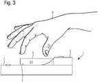
1 shows a top view of a three-dimensional control element.2 shows a top view of the control element according to the invention.3 shows a side view for a second embodiment.4 shows a side view for a third embodiment.
Im Folgenden gelten in den
Das Bedienelement 1 besteht aus zumindest zwei Flächenelementen 2, welche wenigstens partiell durch elektrische Sensoren berührungssensitiv ausgebildet sind. In dem vorliegenden Ausführungsbeispiel sind fünf Flächenelemente 2 vorgesehen, von denen nur zwei beziffert sind. Jedes der fünf Flächenelemente 2 weist einen zentralen, nicht bezifferten Berührpunkt auf, dargestellt durch einen Kreis. Die Flächenelemente 2 dienen dazu, dass eine Bedienperson über eine Berührung mit der Hand oder zumindest einem Finger eine vorgesehene Funktion auslösen kann. Beispiele für eine Funktion sind beispielsweise die Bedienung eines Navigationsgerätes, eines Telefons oder eines Entertainmentsystems.The control element 1 consists of at least two
Erfindungsgemäß ist zwischen den fünf Flächenelementen 2 ein als zylindrisches, feststehendes Drehelement 3 ausgestaltetes Flächenelement angeordnet, wobei eine zylindrische Oberfläche 4 des Drehelementes 3 berührungssensitiv, beispielsweise durch einen kapazitiven Sensor oder einen optischen Sensor oder einen kraftsensitiven Sensor, ausgebildet ist, analog zu den Flächenelementen 2. Mit Hilfe dieser Sensoren kann eine Drehung des Drehelementes 3 sensiert werden, ohne das Drehelement 3 selbst zu drehen. Dargestellt wird das Drehelement 3 durch eine Ausnehmung 5 in dem Bedienelement 1.According to the invention, a surface element configured as a cylindrical, stationary rotating
Des Weiteren weist das vorliegende Ausführungsbeispiel einen umlaufenden Rand 6 auf, der die Ausnehmung 5 umgibt. Somit kann haptisch das Bedienfeld des Bedienelementes 1 erkannt werden, ohne einen Blick auf das Bedienelement 1 werfen zu müssen.Furthermore, the present exemplary embodiment has a
Für eine besonders gute Ergonomie geht das Drehelement 3 in diesem Ausführungsbeispiel entgegen einer Fahrtrichtung des Kraftfahrzeuges in eine Handballenablage 7 über. Vorzugsweise weisen eine obere Fläche des Drehelementes 8 und eine Oberfläche der Handballenablage 7 für eine einfache und ergonomische Bedienung des Bedienelementes 1 zwischen 5 mm und 15 mm Höhenunterschied auf.For particularly good ergonomics, the rotating
Des Weiteren weist die Ausnehmung 5 bevorzugt eine Tiefe zwischen 5 mm und 25 mm auf. Dies ist ein Tiefenbereich, der eine angenehm haptische Bedienung des Drehelements 3 realisiert.Furthermore, the
In einer bevorzugten Ausführungsform ist die obere Fläche des Drehelementes 8 ebenfalls berührungssensitiv ausgebildet, sodass eine Touch-Funktion dargestellt werden kann, welche über Ein- und/oder Mehrfingergesten eingegeben werden kann.In a preferred embodiment, the upper surface of the
Gegenüber dem bekannten Stand der Technik weist das Drehelement 3 an einem Übergang zu der Handballenablage 7 zwischen 180° und 300° eine zylindrische Oberfläche 4 auf, was anstelle der üblichen 360°-Ausformung, d. h. für ein vollzylindrisches Drehelement, für eine normale Bedienung völlig ausreichend ist.Compared to the known prior art, the
In einer weiteren besonders bevorzugten Ausführungsform generiert das Bedienelement 1 nach einer erfolgreichen Bedienung eine optische oder akustische oder haptische Rückmeldung oder eine Kombination daraus.In a further particularly preferred embodiment, the control element 1 generates a visual or acoustic or haptic feedback or a combination thereof after a successful operation.
Als Oberflächenmaterialien für das erfindungsgemäße Bedienelement 1 eignen sich beispielsweise Glas, Holz oder Kunststoffe, sowie fein verarbeitete Metalloberflächen, wie z. B. gebürstetes Aluminium oder Messing oder Edelstahl.Suitable surface materials for the operating element 1 according to the invention are, for example, glass, wood or plastics, as well as finely finished metal surfaces, such as e.g. B. brushed aluminum or brass or stainless steel.
BezugszeichenlisteReference List
- 1.1.
- Bedienelementcontrol element
- 2.2.
- Flächenelementsurface element
- 3.3.
- Drehelementrotary element
- 4.4.
- zylindrische Oberflächecylindrical surface
- 5.5.
- Ausnehmungrecess
- 6.6.
- umlaufender Randsurrounding border
- 7.7.
- Handballenablagepalm rest
- 8.8th.
- obere Flächeupper surface
- 9.9.
- Handhand
ZITATE ENTHALTEN IN DER BESCHREIBUNGQUOTES INCLUDED IN DESCRIPTION
Diese Liste der vom Anmelder aufgeführten Dokumente wurde automatisiert erzeugt und ist ausschließlich zur besseren Information des Lesers aufgenommen. Die Liste ist nicht Bestandteil der deutschen Patent- bzw. Gebrauchsmusteranmeldung. Das DPMA übernimmt keinerlei Haftung für etwaige Fehler oder Auslassungen.This list of the documents cited by the applicant was generated automatically and is included solely for the better information of the reader. The list is not part of the German patent or utility model application. The DPMA assumes no liability for any errors or omissions.
Zitierte PatentliteraturPatent Literature Cited
- DE 102017218506 A1 [0002]DE 102017218506 A1 [0002]
- DE 102008041625 A1 [0003]DE 102008041625 A1 [0003]
- DE 102012206661 A1 [0004]DE 102012206661 A1 [0004]
Claims (9)
Translated fromGermanPriority Applications (4)
| Application Number | Priority Date | Filing Date | Title |
|---|---|---|---|
| DE102020131902.9ADE102020131902A1 (en) | 2020-12-02 | 2020-12-02 | Operating element for a motor vehicle |
| US18/255,054US12222744B2 (en) | 2020-12-02 | 2021-11-04 | Operating element for a motor vehicle |
| PCT/EP2021/080573WO2022117272A1 (en) | 2020-12-02 | 2021-11-04 | Operating element for a motor vehicle |
| CN202180079185.8ACN116490391A (en) | 2020-12-02 | 2021-11-04 | Operating elements for motor vehicles |
Applications Claiming Priority (1)
| Application Number | Priority Date | Filing Date | Title |
|---|---|---|---|
| DE102020131902.9ADE102020131902A1 (en) | 2020-12-02 | 2020-12-02 | Operating element for a motor vehicle |
Publications (1)
| Publication Number | Publication Date |
|---|---|
| DE102020131902A1true DE102020131902A1 (en) | 2022-06-02 |
Family
ID=78598993
Family Applications (1)
| Application Number | Title | Priority Date | Filing Date |
|---|---|---|---|
| DE102020131902.9APendingDE102020131902A1 (en) | 2020-12-02 | 2020-12-02 | Operating element for a motor vehicle |
Country Status (4)
| Country | Link |
|---|---|
| US (1) | US12222744B2 (en) |
| CN (1) | CN116490391A (en) |
| DE (1) | DE102020131902A1 (en) |
| WO (1) | WO2022117272A1 (en) |
Citations (5)
| Publication number | Priority date | Publication date | Assignee | Title |
|---|---|---|---|---|
| DE102004007055A1 (en) | 2004-02-13 | 2005-09-08 | Daimlerchrysler Ag | Operating device for a vehicle |
| DE102008041625A1 (en) | 2008-08-27 | 2010-03-04 | Faurecia Innenraum Systeme Gmbh | Operating element for a display device in a means of transport |
| DE102012206661A1 (en) | 2012-04-23 | 2013-10-24 | Magna Exteriors & Interiors Management Gmbh | Control element for center console in e.g. passenger car, has surface elements partially formed in contact-sensitive manner so that operator triggers intended function by contact with hand, and generation device attached to elements |
| DE112015002578T5 (en) | 2014-05-30 | 2017-04-06 | Toyota Jidosha Kabushiki Kaisha | operating element |
| DE102017218506A1 (en) | 2017-10-17 | 2019-04-18 | Bayerische Motoren Werke Aktiengesellschaft | Device, system and method for operating a graphical user interface and motor vehicle |
Family Cites Families (16)
| Publication number | Priority date | Publication date | Assignee | Title |
|---|---|---|---|---|
| US20070057922A1 (en)* | 2005-09-13 | 2007-03-15 | International Business Machines Corporation | Input having concentric touch pads |
| US8319832B2 (en)* | 2008-01-31 | 2012-11-27 | Denso Corporation | Input apparatus and imaging apparatus |
| JP6273989B2 (en)* | 2014-04-10 | 2018-02-07 | 株式会社デンソー | Operating device and vehicle |
| KR101902434B1 (en)* | 2014-11-13 | 2018-10-01 | 현대자동차주식회사 | Control apparatus using touch and vehicle comprising the same |
| CN105607772B (en)* | 2014-11-13 | 2020-11-03 | 现代自动车株式会社 | Touch input device and vehicle including the same |
| KR101681987B1 (en)* | 2015-04-30 | 2016-12-12 | 현대자동차주식회사 | Control apparatus using touch and vehicle comprising the same |
| KR20170001014A (en)* | 2015-06-25 | 2017-01-04 | 현대자동차주식회사 | Controlling apparatus using touch input, vehicle comprising the same |
| KR101685891B1 (en)* | 2015-07-21 | 2016-12-13 | 현대자동차주식회사 | Controlling apparatus using touch input and controlling method of the same |
| KR20170058742A (en)* | 2015-11-19 | 2017-05-29 | 현대자동차주식회사 | Touch control device, vehicle comprising the same, and manufacturing method thereof |
| KR101741654B1 (en)* | 2015-11-19 | 2017-05-30 | 현대자동차주식회사 | Touch control device, vehicle comprising the same, and manufacturing method thereof |
| US20180081452A1 (en)* | 2016-09-19 | 2018-03-22 | Hyundai Motor Company | Touch input apparatus and vehicle including the same |
| KR102674463B1 (en)* | 2016-12-23 | 2024-06-13 | 현대자동차주식회사 | Vehicle, and control method for the same |
| KR102379602B1 (en)* | 2017-12-28 | 2022-03-29 | 현대자동차주식회사 | Touch control device and vehicle having the same |
| US11376957B2 (en)* | 2018-01-05 | 2022-07-05 | Ghsp, Inc. | Vehicle shifter interface having capacitive touch rotary shifting |
| SE544078C2 (en)* | 2018-06-15 | 2021-12-14 | Ghsp Inc | Rotary shifter with secondary rotary knob |
| KR102777585B1 (en)* | 2018-11-28 | 2025-03-10 | 현대자동차주식회사 | Vehicle and method for controlling thereof |
- 2020
- 2020-12-02DEDE102020131902.9Apatent/DE102020131902A1/enactivePending
- 2021
- 2021-11-04WOPCT/EP2021/080573patent/WO2022117272A1/ennot_activeCeased
- 2021-11-04CNCN202180079185.8Apatent/CN116490391A/enactivePending
- 2021-11-04USUS18/255,054patent/US12222744B2/enactiveActive
Patent Citations (5)
| Publication number | Priority date | Publication date | Assignee | Title |
|---|---|---|---|---|
| DE102004007055A1 (en) | 2004-02-13 | 2005-09-08 | Daimlerchrysler Ag | Operating device for a vehicle |
| DE102008041625A1 (en) | 2008-08-27 | 2010-03-04 | Faurecia Innenraum Systeme Gmbh | Operating element for a display device in a means of transport |
| DE102012206661A1 (en) | 2012-04-23 | 2013-10-24 | Magna Exteriors & Interiors Management Gmbh | Control element for center console in e.g. passenger car, has surface elements partially formed in contact-sensitive manner so that operator triggers intended function by contact with hand, and generation device attached to elements |
| DE112015002578T5 (en) | 2014-05-30 | 2017-04-06 | Toyota Jidosha Kabushiki Kaisha | operating element |
| DE102017218506A1 (en) | 2017-10-17 | 2019-04-18 | Bayerische Motoren Werke Aktiengesellschaft | Device, system and method for operating a graphical user interface and motor vehicle |
Also Published As
| Publication number | Publication date |
|---|---|
| WO2022117272A1 (en) | 2022-06-09 |
| CN116490391A (en) | 2023-07-25 |
| US12222744B2 (en) | 2025-02-11 |
| US20240004416A1 (en) | 2024-01-04 |
Similar Documents
| Publication | Publication Date | Title |
|---|---|---|
| DE102014016328B3 (en) | Method for operating a display device, display device for a motor vehicle and motor vehicle with a display device | |
| EP2909055B1 (en) | Control element for an automobile vehicle and method for producing such a control element | |
| DE102009038044A1 (en) | Vehicle for use with sensor device, has wall in vehicle interior, which is formed by surfaces of covering portions in touch-sensitive area detected by sensor device | |
| EP3347804B1 (en) | Operating device with character input and delete function | |
| DE102016224635A1 (en) | Operating device for an infotainment system of a motor vehicle, method for determining the location of an operator of such a control element | |
| DE102014015403A1 (en) | Operating device for controlling at least one function of at least one motor vehicle side device | |
| DE112019002726T5 (en) | Control system for a vehicle | |
| DE102018009543A1 (en) | operating device | |
| DE102012020164A1 (en) | Operating element for a display device in a motor vehicle | |
| DE102012011179A1 (en) | Device for operating a motor vehicle | |
| DE102014200609B4 (en) | Touch-sensitive control device with recess | |
| DE102009037401A1 (en) | Operating element for working an infotainment system in a vehicle, especially a car, makes multiple operator control actions possible like turning a wheel | |
| DE102020133078A1 (en) | Control system for vehicle | |
| DE102012020570C5 (en) | Control element for a motor vehicle and method for producing a control element | |
| DE102006037725A1 (en) | Motor vehicle has input device, which has display for optical representation of control element and touchscreen arranged on display | |
| WO2021209362A1 (en) | Operating device having active and passive haptics and steering device having such an operating device | |
| DE102020131902A1 (en) | Operating element for a motor vehicle | |
| DE102012019979B4 (en) | Input device for a motor vehicle, in particular a passenger car, and motor vehicles with an input device | |
| DE102019111243A1 (en) | User interface, means of transport and method for operating a user interface | |
| DE102016119844B4 (en) | Fingerprint sensor with rotation gesture functionality | |
| DE102022132215A1 (en) | Operating system for a motor vehicle, motor vehicle and method for operating the operating system | |
| WO2024046612A1 (en) | Controlling a function on board a motor vehicle | |
| WO2019076598A2 (en) | DEVICE, SYSTEM AND METHOD FOR OPERATING A GRAPHIC USER INTERFACE AND MOTOR VEHICLE | |
| DE102013101339A1 (en) | operating element | |
| DE102021127036A1 (en) | System for operating a motor vehicle |
Legal Events
| Date | Code | Title | Description |
|---|---|---|---|
| R163 | Identified publications notified |