DE102020130863A1 - Method for the automated detection of a switching matrix of electrical consumables connected to a three-phase distribution network, in particular charging devices for electrical energy storage devices and charging devices - Google Patents
Method for the automated detection of a switching matrix of electrical consumables connected to a three-phase distribution network, in particular charging devices for electrical energy storage devices and charging devicesDownload PDFInfo
- Publication number
- DE102020130863A1 DE102020130863A1DE102020130863.9ADE102020130863ADE102020130863A1DE 102020130863 A1DE102020130863 A1DE 102020130863A1DE 102020130863 ADE102020130863 ADE 102020130863ADE 102020130863 A1DE102020130863 A1DE 102020130863A1
- Authority
- DE
- Germany
- Prior art keywords
- phase
- voltage
- consumable
- distribution network
- connection
- Prior art date
- Legal status (The legal status is an assumption and is not a legal conclusion. Google has not performed a legal analysis and makes no representation as to the accuracy of the status listed.)
- Withdrawn
Links
- 238000000034methodMethods0.000titleclaimsabstractdescription36
- 239000011159matrix materialSubstances0.000titleclaimsabstractdescription9
- 238000001514detection methodMethods0.000titleclaimsabstractdescription7
- 238000004146energy storageMethods0.000titleclaimsabstractdescription7
- 238000005259measurementMethods0.000claimsabstractdescription7
- 238000012544monitoring processMethods0.000claimsabstractdescription7
- 238000004891communicationMethods0.000claimsdescription9
- 238000012360testing methodMethods0.000claimsdescription9
- 230000005540biological transmissionEffects0.000claimsdescription4
- 230000001360synchronised effectEffects0.000claimsdescription2
- 239000004020conductorSubstances0.000description12
- 230000007935neutral effectEffects0.000description7
- BUHVIAUBTBOHAG-FOYDDCNASA-N(2r,3r,4s,5r)-2-[6-[[2-(3,5-dimethoxyphenyl)-2-(2-methylphenyl)ethyl]amino]purin-9-yl]-5-(hydroxymethyl)oxolane-3,4-diolChemical compoundCOC1=CC(OC)=CC(C(CNC=2C=3N=CN(C=3N=CN=2)[C@H]2[C@@H]([C@H](O)[C@@H](CO)O2)O)C=2C(=CC=CC=2)C)=C1BUHVIAUBTBOHAG-FOYDDCNASA-N0.000description1
- 230000001419dependent effectEffects0.000description1
- 238000009434installationMethods0.000description1
- 230000005405multipoleEffects0.000description1
- 239000004065semiconductorSubstances0.000description1
- 230000002123temporal effectEffects0.000description1
- 238000011144upstream manufacturingMethods0.000description1
Images


Classifications
- H—ELECTRICITY
- H02—GENERATION; CONVERSION OR DISTRIBUTION OF ELECTRIC POWER
- H02J—CIRCUIT ARRANGEMENTS OR SYSTEMS FOR SUPPLYING OR DISTRIBUTING ELECTRIC POWER; SYSTEMS FOR STORING ELECTRIC ENERGY
- H02J3/00—Circuit arrangements for AC mains or AC distribution networks
- H02J3/24—Arrangements for preventing or reducing oscillations of power in networks
- H—ELECTRICITY
- H02—GENERATION; CONVERSION OR DISTRIBUTION OF ELECTRIC POWER
- H02J—CIRCUIT ARRANGEMENTS OR SYSTEMS FOR SUPPLYING OR DISTRIBUTING ELECTRIC POWER; SYSTEMS FOR STORING ELECTRIC ENERGY
- H02J13/00—Circuit arrangements for providing remote indication of network conditions, e.g. an instantaneous record of the open or closed condition of each circuitbreaker in the network; Circuit arrangements for providing remote control of switching means in a power distribution network, e.g. switching in and out of current consumers by using a pulse code signal carried by the network
- H02J13/00002—Circuit arrangements for providing remote indication of network conditions, e.g. an instantaneous record of the open or closed condition of each circuitbreaker in the network; Circuit arrangements for providing remote control of switching means in a power distribution network, e.g. switching in and out of current consumers by using a pulse code signal carried by the network characterised by monitoring
- H—ELECTRICITY
- H02—GENERATION; CONVERSION OR DISTRIBUTION OF ELECTRIC POWER
- H02J—CIRCUIT ARRANGEMENTS OR SYSTEMS FOR SUPPLYING OR DISTRIBUTING ELECTRIC POWER; SYSTEMS FOR STORING ELECTRIC ENERGY
- H02J3/00—Circuit arrangements for AC mains or AC distribution networks
- H02J3/007—Arrangements for selectively connecting the load or loads to one or several among a plurality of power lines or power sources
- H—ELECTRICITY
- H02—GENERATION; CONVERSION OR DISTRIBUTION OF ELECTRIC POWER
- H02J—CIRCUIT ARRANGEMENTS OR SYSTEMS FOR SUPPLYING OR DISTRIBUTING ELECTRIC POWER; SYSTEMS FOR STORING ELECTRIC ENERGY
- H02J2203/00—Indexing scheme relating to details of circuit arrangements for AC mains or AC distribution networks
- H02J2203/20—Simulating, e g planning, reliability check, modelling or computer assisted design [CAD]
- Y—GENERAL TAGGING OF NEW TECHNOLOGICAL DEVELOPMENTS; GENERAL TAGGING OF CROSS-SECTIONAL TECHNOLOGIES SPANNING OVER SEVERAL SECTIONS OF THE IPC; TECHNICAL SUBJECTS COVERED BY FORMER USPC CROSS-REFERENCE ART COLLECTIONS [XRACs] AND DIGESTS
- Y02—TECHNOLOGIES OR APPLICATIONS FOR MITIGATION OR ADAPTATION AGAINST CLIMATE CHANGE
- Y02E—REDUCTION OF GREENHOUSE GAS [GHG] EMISSIONS, RELATED TO ENERGY GENERATION, TRANSMISSION OR DISTRIBUTION
- Y02E60/00—Enabling technologies; Technologies with a potential or indirect contribution to GHG emissions mitigation
- Y—GENERAL TAGGING OF NEW TECHNOLOGICAL DEVELOPMENTS; GENERAL TAGGING OF CROSS-SECTIONAL TECHNOLOGIES SPANNING OVER SEVERAL SECTIONS OF THE IPC; TECHNICAL SUBJECTS COVERED BY FORMER USPC CROSS-REFERENCE ART COLLECTIONS [XRACs] AND DIGESTS
- Y02—TECHNOLOGIES OR APPLICATIONS FOR MITIGATION OR ADAPTATION AGAINST CLIMATE CHANGE
- Y02T—CLIMATE CHANGE MITIGATION TECHNOLOGIES RELATED TO TRANSPORTATION
- Y02T10/00—Road transport of goods or passengers
- Y02T10/60—Other road transportation technologies with climate change mitigation effect
- Y02T10/70—Energy storage systems for electromobility, e.g. batteries
- Y—GENERAL TAGGING OF NEW TECHNOLOGICAL DEVELOPMENTS; GENERAL TAGGING OF CROSS-SECTIONAL TECHNOLOGIES SPANNING OVER SEVERAL SECTIONS OF THE IPC; TECHNICAL SUBJECTS COVERED BY FORMER USPC CROSS-REFERENCE ART COLLECTIONS [XRACs] AND DIGESTS
- Y02—TECHNOLOGIES OR APPLICATIONS FOR MITIGATION OR ADAPTATION AGAINST CLIMATE CHANGE
- Y02T—CLIMATE CHANGE MITIGATION TECHNOLOGIES RELATED TO TRANSPORTATION
- Y02T10/00—Road transport of goods or passengers
- Y02T10/60—Other road transportation technologies with climate change mitigation effect
- Y02T10/7072—Electromobility specific charging systems or methods for batteries, ultracapacitors, supercapacitors or double-layer capacitors
- Y—GENERAL TAGGING OF NEW TECHNOLOGICAL DEVELOPMENTS; GENERAL TAGGING OF CROSS-SECTIONAL TECHNOLOGIES SPANNING OVER SEVERAL SECTIONS OF THE IPC; TECHNICAL SUBJECTS COVERED BY FORMER USPC CROSS-REFERENCE ART COLLECTIONS [XRACs] AND DIGESTS
- Y02—TECHNOLOGIES OR APPLICATIONS FOR MITIGATION OR ADAPTATION AGAINST CLIMATE CHANGE
- Y02T—CLIMATE CHANGE MITIGATION TECHNOLOGIES RELATED TO TRANSPORTATION
- Y02T90/00—Enabling technologies or technologies with a potential or indirect contribution to GHG emissions mitigation
- Y02T90/10—Technologies relating to charging of electric vehicles
- Y02T90/12—Electric charging stations
- Y—GENERAL TAGGING OF NEW TECHNOLOGICAL DEVELOPMENTS; GENERAL TAGGING OF CROSS-SECTIONAL TECHNOLOGIES SPANNING OVER SEVERAL SECTIONS OF THE IPC; TECHNICAL SUBJECTS COVERED BY FORMER USPC CROSS-REFERENCE ART COLLECTIONS [XRACs] AND DIGESTS
- Y04—INFORMATION OR COMMUNICATION TECHNOLOGIES HAVING AN IMPACT ON OTHER TECHNOLOGY AREAS
- Y04S—SYSTEMS INTEGRATING TECHNOLOGIES RELATED TO POWER NETWORK OPERATION, COMMUNICATION OR INFORMATION TECHNOLOGIES FOR IMPROVING THE ELECTRICAL POWER GENERATION, TRANSMISSION, DISTRIBUTION, MANAGEMENT OR USAGE, i.e. SMART GRIDS
- Y04S10/00—Systems supporting electrical power generation, transmission or distribution
- Y04S10/30—State monitoring, e.g. fault, temperature monitoring, insulator monitoring, corona discharge
- Y—GENERAL TAGGING OF NEW TECHNOLOGICAL DEVELOPMENTS; GENERAL TAGGING OF CROSS-SECTIONAL TECHNOLOGIES SPANNING OVER SEVERAL SECTIONS OF THE IPC; TECHNICAL SUBJECTS COVERED BY FORMER USPC CROSS-REFERENCE ART COLLECTIONS [XRACs] AND DIGESTS
- Y04—INFORMATION OR COMMUNICATION TECHNOLOGIES HAVING AN IMPACT ON OTHER TECHNOLOGY AREAS
- Y04S—SYSTEMS INTEGRATING TECHNOLOGIES RELATED TO POWER NETWORK OPERATION, COMMUNICATION OR INFORMATION TECHNOLOGIES FOR IMPROVING THE ELECTRICAL POWER GENERATION, TRANSMISSION, DISTRIBUTION, MANAGEMENT OR USAGE, i.e. SMART GRIDS
- Y04S40/00—Systems for electrical power generation, transmission, distribution or end-user application management characterised by the use of communication or information technologies, or communication or information technology specific aspects supporting them
- Y04S40/20—Information technology specific aspects, e.g. CAD, simulation, modelling, system security
Landscapes
- Engineering & Computer Science (AREA)
- Power Engineering (AREA)
- Remote Monitoring And Control Of Power-Distribution Networks (AREA)
Abstract
Translated fromGermanDescription
Translated fromGermanDie Erfindung betrifft ein Verfahren zur Erkennung einer Schaltmatrix von wenigstens zwei mehrpolig an ein Dreiphasen-Verteilnetz angeschlossenen elektrischen Verbrauchsmitteln, insbesondere von an das Dreiphasen-Verteilnetz angeschlossenen Ladeeinrichtungen für einen elektrischen Energiespeicher, wobei die Verbrauchsmittel jeweils eine Vielzahl von Phasenanschlüssen aufweisen, die an jeweils eine Phase des Verteilnetzes angeschlossen sind, wobei die Anschlussbelegung wenigstens eines ersten elektrischen Verbrauchsmittels bekannt ist.The invention relates to a method for detecting a switching matrix of at least two electrical consumables that are connected to a three-phase distribution network with multiple poles, in particular charging devices for an electrical energy storage device that are connected to the three-phase distribution network, the consumables each having a large number of phase connections that are each connected to a Phase of the distribution network are connected, the pin assignment of at least a first electrical consumable is known.
Die Erfindung betrifft weiterhin eine Ladeeinrichtung als elektrisches Verbrauchsmittel, welche zur Durchführung des Verfahrens ausgebildet ist.The invention also relates to a charging device as an electrical consumable, which is designed to carry out the method.
Dreiphasige Stromnetze werden häufig mit einphasigen Verbrauchern in Form von elektrischen Betriebsmitteln, elektrischen Speichern, Generatoren oder dergleichen unsymmetrisch belastet. Elektrische Verbrauchsmittel sind beispielsweise auch Ladeeinrichtungen für Elektrofahrzeuge, die teilweise einphasig oder auch zweiphasig mit hoher Leistung und mit hoher Gleichzeitigkeit betrieben werden. Die elektrischen Verbrauchsmittel sind in der Regel an ein bis drei Außenleitern gegen den Neutralleiter bzw. Nullleiter oder an mehreren Außenleitern ohne Neutralleiter angeschlossen. Die unsymmetrische Belastung des Verteilnetzes, welches in Europa häufig als Dreiphasen-Niederstromnetz mit drei Phasenleitern (400 V Phase zu Phase) und einem Nullleiter (230 V Phase zu Nullleiter) ausgebildet ist, ist grundsätzlich im Hinblick auf die Qualität der Versorgungsspannung an einem Netzanschlusspunkt nicht wünschenswert.Three-phase power grids are often asymmetrically loaded with single-phase loads in the form of electrical equipment, electrical storage devices, generators or the like. Electrical consumables are, for example, charging devices for electric vehicles, some of which are operated in one phase or in two phases with high power and high simultaneity. The electrical consumables are usually connected to one to three outer conductors against the neutral conductor or zero conductor or to several outer conductors without a neutral conductor. The asymmetric load of the distribution grid, which in Europe is often designed as a three-phase low-current grid with three phase conductors (400 V phase to phase) and one neutral conductor (230 V phase to neutral conductor), is fundamentally unacceptable with regard to the quality of the supply voltage at a grid connection point desirable.
Dieses Problem ist bereits in der
Aus der europäischen Patentanmeldung
Üblicherweise werden Ladestationen für Elektrofahrzeuge in einer sogenannten Schaltmatrix angeschlossen, um eine Belastung des elektrischen Verteilnetzes zu reduzieren. Hierzu wird eine erste Ladestation so angeschlossen, dass die erste Phase des Verteilnetzes an dem Anschluss der ersten Phase der Ladestation, die zweite Phase des Verteilnetzes an dem Anschluss der zweiten Phase der Ladestation etc. anliegt. Eine zweite oder weitere Ladestation, welche sich in der Nähe der ersten Ladestation befindet, wird dann so angeschlossen, dass die zweite Phase des Verteilnetzes an dem Anschluss der ersten Phase der Ladestation und die dritte Phase des Verteilnetzes an dem Anschluss der zweiten Phase der Ladestation anliegt. Bei der Installation jeder Ladestation ist es erforderlich, dass ein Monteur jeweils vermerkt, wie die Ladestation an das Verteilnetz angeschlossen ist und dabei die Anschlussinformationen der vorherigen Ladestation berücksichtigt. Das ist zeitaufwendig und fehlerträchtig.Charging stations for electric vehicles are usually connected in a so-called switching matrix in order to reduce the load on the electrical distribution network. For this purpose, a first charging station is connected in such a way that the first phase of the distribution network is connected to the connection of the first phase of the charging station, the second phase of the distribution network is connected to the connection of the second phase of the charging station, etc. A second or additional charging station, which is located near the first charging station, is then connected in such a way that the second phase of the distribution network is connected to the connection of the first phase of the charging station and the third phase of the distribution network is connected to the connection of the second phase of the charging station . When installing each charging station, it is necessary for a fitter to note how the charging station is connected to the distribution network, taking into account the connection information from the previous charging station. This is time-consuming and error-prone.
Der Erfindung liegt die Aufgabe zugrunde, ein Verfahren und eine Ladeeinrichtung bereitzustellen, die die zuvor beschriebenen Nachteile vermeiden. Insbesondere soll erfindungsgemäß eine automatisierte Erkennung der Schaltmatrix von wenigstens zwei mehrpolig an ein Dreiphasen-Verteilnetz angeschlossenen elektrischen Verbrauchsmitteln, insbesondere Ladeeinrichtungen, ermöglicht werden.The invention is based on the object of providing a method and a charging device which avoid the disadvantages described above. In particular, according to the invention, automated detection of the switching matrix of at least two electrical consumables, in particular charging devices, connected to a three-phase distribution network with multiple poles should be made possible.
Die der Erfindung zugrunde liegende Aufgabe wird gelöst durch die Bereitstellung eines Verfahrens mit den Merkmalen des Anspruchs 1 sowie durch die Bereitstellung einer Ladeeinrichtung mit den Merkmalen des Anspruchs 12.The object on which the invention is based is achieved by providing a method with the features of claim 1 and by providing a charging device having the features of claim 12.
Vorteilhafte Ausgestaltungen der Erfindung ergeben sich aus den Unteransprüchen.Advantageous configurations of the invention result from the dependent claims.
Nach einem Gesichtspunkt der Erfindung wird ein Verfahren zur automatisierten Erkennung einer Schaltmatrix von wenigstens zwei mehrpolig an ein Dreiphasen-Verteilnetz angeschlossenen elektrischen Verbrauchsmitteln, insbesondere von Ladeeinrichtungen für elektrische Energiespeicher vorgeschlagen, wobei die Verbrauchsmittel jeweils eine Vielzahl von Phasenanschlüssen aufweisen, die an jeweils eine Phase des Verteilnetzes angeschlossen sind, wobei die Anschlussbelegung wenigstens eines ersten Verbrauchsmittels bekannt ist, wobei das Verfahren die Messung und/oder Überwachung eines zeitlichen Verlaufs und/oder einer Amplitude und/oder eines momentanen Wertes der Spannung an den Phasenanschlüssen wenigstens eines zweiten Verbrauchsmittels und/oder des zweiten Verbrauchsmittels umfasst und die Anschlussbelegung an wenigstens dem zweiten Verbrauchsmittel durch Abgleich der Spannungsinformationen des ersten und des zweiten Verbrauchsmittels ermittelt wird.According to one aspect of the invention, a method is proposed for the automated detection of a switching matrix of at least two electrical consumables connected to a three-phase distribution network with multiple poles, in particular charging devices for electrical energy storage devices, with the consumables each having a large number of phase connections which are each connected to one phase of the are connected to the distribution network, the connection assignment of at least one first consumer being known, the method including the measurement and/or monitoring of a time profile and/or an amplitude and/or an instantaneous value of the voltage at the phase connections of at least one second consumer and/or the includes the second consumable and the pin assignment is determined at least on the second consumable by comparing the voltage information of the first and the second consumable.
Unter einer Schaltmatrix im Sinne der vorliegenden Erfindung ist im Wesentlichen eine Anschlusszuordnung wenigstens eines Verbrauchsmittels, insbesondere in Form einer Ladeeinrichtung, mit mehreren Phasenanschlüssen an ein Verteilnetz mit mehreren Phasen zu verstehen. Das Verbrauchsmittel bzw. die Ladeeinrichtung kann beispielsweise ein- oder mehrphasig an einen dem elektrischen Energiespeicher vorgeschalteten Gleichrichter angeschlossen sein.A switching matrix within the meaning of the present invention essentially means a connection assignment of at least one consumer, in particular in the form of a charging device, with multiple phase connections to a distribution network with multiple phases. The consumable or the charging device can, for example, be connected in one or more phases to a rectifier connected upstream of the electrical energy store.
Mittels des erfindungsgemäßen Verfahrens kann beim Anschluss eines zweiten oder weiteren Verbrauchsmittels an das gleiche Verteilnetz an dem betreffenden Verbrauchsmittel automatisch zumindest teilweise die Anschlussbelegung dieses Verbrauchsmittels relativ zu der Anschlussbelegung des ersten Verbrauchsmittels erkannt werden. D. h., dass das gerade angeschlossene zweite oder weitere Verbrauchsmittel automatisch erkennt, an welchen Phasen des Verteilnetzes es angeschlossen ist, die von der ersten oder einer anderen Ladeeinrichtung belegt werden, vorausgesetzt, dass bereits ein erstes Verbrauchsmittel mit bekannter Anschlussbelegung in Betrieb genommen wurde. Dabei ist erfindungsgemäß vorgesehen, dass das bereits angeschlossene erste Verbrauchsmittel und wenigstens das zweite Verbrauchsmittel einen zeitlichen Verlauf und oder eine Amplitude und/oder einen momentanen Wert der Spannung an wenigstens einem Phasenanschluss überwachen und ein Abgleich der Spannungsinformationen der ersten und der zweiten Verbrauchsmittel untereinander erfolgt.By means of the method according to the invention, when a second or further consumable is connected to the same distribution network on the consumable in question, the connection assignment of this consumable relative to the connection assignment of the first consumable can be automatically at least partially recognized. This means that the second or further consumer device that is just connected automatically recognizes which phases of the distribution network it is connected to that are occupied by the first or another charging device, provided that a first consumer device with a known connection assignment has already been put into operation . The invention provides that the first consumable that is already connected and at least the second consumable monitor a time profile and/or an amplitude and/or an instantaneous value of the voltage at at least one phase connection and that the voltage information of the first and second consumables is compared with one another.
Bei einer bevorzugten Variante des Verfahrens gemäß der Erfindung kann vorgesehen sein, dass der Abgleich der Spannungsinformationen über eine vorzugsweise unmittelbare Datenkommunikation zwischen dem ersten und dem zweiten Verbrauchsmittel durchgeführt wird.In a preferred variant of the method according to the invention, it can be provided that the comparison of the voltage information is carried out via a preferably direct data communication between the first and the second consumable.
Der Abgleich kann derart vorgesehen sein, dass der von dem ersten Verbrauchsmittel überwachte zeitliche Verlauf der Spannung an wenigstens einem Phasenanschluss des ersten Verbrauchsmittels an das zweite Verbrauchsmittel übermittelt wird und dass der zeitliche Verlauf der Spannung an dem Phasenanschluss des ersten Verbrauchsmittels mit dem zeitlichen Verlauf der Spannung an den Phasenanschlüssen des zweiten Verbrauchsmittels verglichen wird. Aus dem Vergleich kann das zweite Verbrauchsmittel in vorteilhafter Art und Weise erkennen, welche Phasenanschlüsse des ersten Verbrauchsmittels welche Phase des Verteilnetzes belegen. Hierzu ist es beispielsweise ausreichend, wenn das erste Verbrauchsmittel den zeitlichen Verlauf der Spannung an einem ersten Phasenanschluss überwacht. Da alle Phasen des Verteilnetzes um einen vorgegebenen Phasenwinkel, üblicherweise 120°, zueinander versetzt sind, kann das zweite Verbrauchsmittel, wenn es die Information bezüglich des von dem ersten Verbrauchsmittel überbrachten Spannungsverlaufs erhält, erkennen, welcher seiner Phasenanschlüsse mit einer Phase verbunden ist, deren zeitlicher Spannungsverlauf dem von dem ersten Verbrauchsmittel gemessenen und/oder überwachten zeitlichen Spannungsverlauf entspricht.The adjustment can be provided in such a way that the time profile of the voltage monitored by the first consumable at at least one phase connection of the first consumable is transmitted to the second consumable and that the time profile of the voltage at the phase connection of the first consumable matches the time profile of the voltage is compared at the phase terminals of the second consumable. From the comparison, the second consumer can advantageously recognize which phase connections of the first consumer occupy which phase of the distribution network. To this end, it is sufficient, for example, if the first consumable monitors the course of the voltage over time at a first phase connection. Since all phases of the distribution grid are offset from one another by a predetermined phase angle, usually 120°, the second consumer can, when it receives the information regarding the voltage curve transmitted by the first consumer, recognize which of its phase connections is connected to a phase whose temporal Voltage curve corresponds to the voltage curve measured and/or monitored by the first consumable.
Dabei ist es vorteilhaft, wenn das erste und das zweite Verbrauchsmittel oder alle am Verteilnetz angeschlossenen Verbrauchsmittel die gleiche Zeitbasis verwenden. Bei einer vorteilhaften Variante der Erfindung ist deshalb vorgesehen, dass die Messung und/oder Erfassung des zeitlichen Verlaufs der Spannung an den Phasenanschlüssen des ersten und zweiten Verbrauchsmittels zeitlich miteinander synchronisiert werden, vorzugsweise unter Verwendung eines Datenprotokolls zur Zeitsynchronisation.It is advantageous if the first and the second consumer or all of the consumers connected to the distribution network use the same time base. In an advantageous variant of the invention, it is therefore provided that the measurement and/or detection of the time profile of the voltage at the phase connections of the first and second consumables are synchronized with one another in terms of time, preferably using a data protocol for time synchronization.
Die Datenkommunikation kann beispielsweise drahtgebunden über ein lokales Netzwerk, beispielsweise über Ethernet und/oder oder drahtlos über ein Mobilfunknetz durchgeführt werden.The data communication can be carried out, for example, in a wired manner via a local network, for example via Ethernet and/or wirelessly via a mobile radio network.
Eine zeitliche Synchronisation kann beispielsweise mithilfe des IEEE-1588-Protokolls, das auch als Precision Time Protocol (PTP) bezeichnet wird, erfolgen.Time synchronization can, for example, take place using the IEEE 1588 protocol, which is also referred to as Precision Time Protocol (PTP).
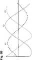
Bei einer alternativen Variante des Verfahrens gemäß der Erfindung ist vorgesehen, dass in einem Testbetrieb oder Testmodus des ersten Verbrauchsmittels wenigstens eine Phase bzw. wenigstens ein Phasenleiter des ersten Verbrauchsmittels wenigstens zeitweise belastet wird, sodass der daraus resultierende Spannungsabfall an einer Phase des Verteilnetzes an einem Phasenanschluss des zweiten Verbrauchsmittels zwecks Erkennung der Anschlussbelegung des zweiten Verbrauchsmittels messbar ist. Diese Variante umfasst das Messen einer Amplitude und/oder eines momentanen Werts der Spannung der Phasen des Verteilnetzes an den Phasenanschlüssen des zweiten Verbrauchsmittels. Auch ohne zeitliche Synchronisation der Verbrauchsmittel kann das zweite Verbrauchsmittel auf diese Art und Weise erkennen, welche Phase des Verteilnetzes durch das erste Verbrauchsmittel belastet wird, wenn bekannt ist, welche Phasen des Verteilnetzes mit welchen Phasenanschlüssen des ersten Verbrauchsmittels belegt sind. Diese Variante des Verfahrens schließt nicht aus, dass das erste und das zweite Verbrauchsmittel bzw. alle Verbrauchsmittel oder Ladeeinrichtungen, die an das Verteilnetz angeschlossen sind, miteinander kommunizieren, sodass beispielsweise das erste Verbrauchsmittel dem zweiten Verbrauchsmittel mitteilt, wie hoch die aktuelle Amplitude der Spannung der belasteten Phase ist.In an alternative variant of the method according to the invention, it is provided that in a test operation or test mode of the first consumable, at least one phase or at least one phase conductor of the first consumable is loaded at least temporarily, so that the resulting voltage drop in a phase of the distribution network is at a phase connection of the second consumable is measurable for the purpose of detecting the connection assignment of the second consumable. This variant includes measuring an amplitude and/or an instantaneous value of the voltage of the phases of the distribution network at the phase terminals of the second consumer. Even without time synchronization of the consumables, the second consumable can recognize in this way which phase of the distribution network is loaded by the first consumable if it is known which phases of the distribution network are occupied by which phase connections of the first consumable. This variant of the method does not preclude the first and second consumables or all consumables or charging devices that are connected to the distribution network from communicating with one another, so that, for example, the first consumable informs the second consumable how high the current amplitude of the voltage of the loaded phase.
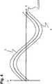
Zweckmäßigerweise wird beim Abgleich der Spannungsinformationen eine Spannungstoleranz berücksichtigt. Das ist sinnvoll und zweckmäßig, um Messtoleranzen der einzelnen elektrischen Verbrauchsmittel zu berücksichtigen. Hierzu kann beispielsweise vorgesehen sein, dass die Spannungstoleranz bei einer Überwachung des zeitlichen Verlaufs der Spannung an einem Phasenanschluss in Form einer Bandbreite und/oder einer Hüllkurve des zeitlichen Verlaufs der Spannung berücksichtigt wird. Ebenso ist es sinnvoll und im Rahmen der vorliegenden Erfindung, dass eine Messtoleranz bei der Messung von Amplitude und momentanem Wert der Spannung berücksichtigt wird.A voltage tolerance is expediently taken into account when comparing the voltage information. This makes sense and is useful in order to take measurement tolerances of the individual electrical consumables into account. For this purpose, it can be provided, for example, that the voltage tolerance is taken into account when monitoring the time profile of the voltage at a phase connection in the form of a bandwidth and/or an envelope curve of the time profile of the voltage. It is also useful and within the scope of the present invention that a measurement tolerance is taken into account when measuring the amplitude and instantaneous value of the voltage.
Zweckmäßigerweise ist das Verteilnetz als Dreiphasen-Niederspannungsstromkreis mit Wechselspannung ausgebildet. Unter Niederspannung im Sinne der vorliegenden Anmeldung sind Spannungen bis 1000 V zu verstehen.The distribution network is expediently designed as a three-phase low-voltage circuit with alternating voltage. In the context of the present application, low voltage is to be understood as meaning voltages of up to 1000 V.
Die elektrischen Verbrauchsmittel bzw. Ladeeinrichtungen gemäß der Erfindung können beispielsweise als Ladestationen für Batteriespeicher von Elektrofahrzeugen ausgebildet sein. Das Verfahren gemäß der Erfindung ist allerdings grundsätzlich auf Ladeeinrichtungen jedweder Art, beispielsweise auf Ladeeinrichtungen für elektrische Energiespeicher in privaten Haushalten oder auf andere elektrische Verbrauchsmittel anwendbar.The electrical consumables or charging devices according to the invention can be designed, for example, as charging stations for battery storage devices in electric vehicles. However, the method according to the invention can in principle be applied to charging devices of any type, for example charging devices for electrical energy storage devices in private households or to other electrical consumables.
Ein weiterer Gesichtspunkt der Erfindung betrifft eine Ladeeinrichtung für einen elektrischen Energiespeicher mit wenigstens drei Phasenanschlüssen an ein Dreiphasen-Verteilnetz, welches zur Durchführung des Verfahrens mit einem oder mehreren der vorstehend beschriebenen Verfahrensmerkmale ausgebildet ist.A further aspect of the invention relates to a charging device for an electrical energy store with at least three phase connections to a three-phase distribution network, which is designed to carry out the method with one or more of the method features described above.
Die Ladeeinrichtung zeichnet sich insbesondere durch Mittel zur Messung und/oder Erfassung eines zeitlichen Verlaufs und/oder einer Amplitude und/oder eines momentanen Werts der Spannung an wenigstens einem Phasenanschluss wenigstens eine Ladeeinrichtung sowie Mittel zur Kommunikation des zeitlichen Verlaufs und/oder der Amplitude und/oder eines momentanen Werts der Spannung an wenigstens eine weitere Ladeeinrichtung aus.The charging device is characterized in particular by means for measuring and/or recording a time profile and/or an amplitude and/or an instantaneous value of the voltage at at least one phase connection at least one charging device and means for communicating the time profile and/or the amplitude and/or or an instantaneous value of the voltage to at least one further charging device.
Die Ladeeinrichtung umfasst vorzugsweise wenigstens eine Kommunikationsschnittstelle zur Datenübertragung und/oder Datenfernübertragung an eine weitere Ladeeinrichtung.The charging device preferably comprises at least one communication interface for data transmission and/or remote data transmission to a further charging device.
Die Ladeeinrichtung kann wenigstens einen schaltbaren Testwiderstand zum Betrieb in einem Testmodus umfassen, der von einer an das Verteilnetz angeschlossenen weiteren Ladeeinrichtung detektierbar ist.The charging device can include at least one switchable test resistor for operation in a test mode, which can be detected by a further charging device connected to the distribution grid.
Die Erfindung wird nachstehend anhand zweier Ausführungsbeispiele unter Bezugnahme auf die beigefügten Zeichnungen erläutert.The invention is explained below using two exemplary embodiments with reference to the accompanying drawings.
Es zeigen:
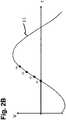
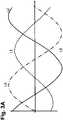
1 eine Anschlusszuordnung einer ersten, zweiten und dritten Ladestation für Elektrofahrzeuge, die mehrpolig an ein Verteilnetz angeschlossen sind,2 den zeitlichen Verlauf der an den Ladestationen überwachten Spannung der Phasen des Verteilnetzes, wobei2A die Überwachung an der ersten Ladestation und2B die Überwachung an der zweiten Ladestation zeigt,3 eine der2 entsprechende Darstellung des an den Ladestationen detektieren Spannungsverlaufs bezogen auf ein zweites Ausführungsbeispiel der Erfindung und4 die Darstellung eines Toleranzbereichs in Form einer oberen und unteren Hüllkurve des Spannungsverlaufs einer Phase.
1 a connection assignment of a first, second and third charging station for electric vehicles that are multi-pole connected to a distribution network,2 the time profile of the voltage of the phases of the distribution network monitored at the charging stations, where2A monitoring at the first charging station and2 B the monitoring at the second charging station shows3 one of the2 corresponding representation of the detected at the charging stations voltage curve based on a second embodiment of the invention and4 the representation of a tolerance range in the form of an upper and lower envelope curve of the voltage curve of a phase.
In
Bei dem beschriebenen Ausführungsbeispiel sind die Ladestationen 1, 2, 3 jeweils als Ladestationen für den elektrischen Speicher eines Elektrofahrzeugs ausgebildet. Die Ladestationen 1, 2, 3 sind jeweils mehrphasig mit Phasenanschlüssen AL1, AL2 und AL3 an das Verteilnetz 4 angeschlossen, wobei die Phase L1 des Verteilnetzes 4 mit dem Phasenanschluss AL1 der ersten Ladestation 1 belegt ist, die Phase L2 des Verteilnetzes 4 mit dem Phasenanschluss AL2 der ersten Ladestation 1 belegt ist und die Phase L3 des Verteilnetzes 4 mit dem Phasenanschluss AL3 der ersten Ladestation 1 belegt ist.In the exemplary embodiment described, the charging
Die zweite Ladestation 2 ist mit ihrem Phasenanschluss AL1 an die zweite Phase L2 des Verteilnetzes 4, mit dem Phasenanschluss AL2 an die dritte Phase L3 des Verteilnetzes und mit dem Phasenanschluss AL 3 an die erste Phase L 1 des Verteilnetzes 4 angeschlossen, wohingegen die dritte Ladestation 3 mit dem Phasenanschluss AL 1 an die dritte Phase L3 des Verteilnetzes, mit dem Phasenanschluss AL2 an die erste Phase des Verteilnetzes und mit dem Phasenanschluss A3 an die zweite Phase L2 des Verteilnetzes 4 angeschlossen ist. Eine weitere Ladestation sollte dann wieder entsprechend der ersten Ladestation 1 angeschlossen sein, d. h. weitere Ladestationen sollten die Reihe entsprechend fortsetzen, um eine symmetrische Belastung des Verteilnetzes 4 bei der zeitgleichen Durchführung mehrerer Ladevorgänge zu erreichen, bei denen der elektrische Energiespeicher jeweils nur eine einphasige Energiesenke bildet.The
Bei dem erfindungsgemäßen Verfahren nach dem ersten Ausführungsbeispiel ist vorgesehen, dass alle an das Verteilnetz 4 angeschlossenen Ladestationen 1, 2 und 3 den zeitlichen Verlauf der Phasen L1, L2 und L3 messen und überwachen. Weiterhin umfasst jede Ladestation 1, 2, 3 eine Datenschnittstelle und kommuniziert beispielsweise über ein 5G Mobilfunknetz oder über Ethernet mit den jeweils anderen Ladestationen. Die Anschlussbelegung der ersten Ladestation 1 ist von vornherein bekannt und festgelegt. Die Bezeichnung der Phasen L1, L2 und L3 des Verteilnetzes 4 wird durch den Anschluss der ersten Ladestation 1 festgelegt. Der an der ersten Ladestation 1 gemessene zeitliche Verlauf der Spannung an den Phasen L1, L2 und L3 des Verteilnetzes 4 wird über eine Datenkommunikation, entweder drahtgebunden oder drahtlos, an einer andere Ladestationen 2, 3 übermittelt, wobei die Spannungsinformation mit einem Zeitstempel nach einem genormten Datenprotokoll, beispielsweise nach dem IEEE-1588-Protokoll. versehen wird, sodass sichergestellt ist alle Ladestationen 1, 2, 3 die gleiche Zeitbasis verwenden. Die ersten Ladestation 1 kann unter Verwendung des Zeitstempels die von dieser überwachten Spannungsverläufe an den einzelnen Phasen L1, L2, L3 mit einer Belegungsinformation, d. h. der Zuordnung der Phasenanschlüsse AL1, AL2 und AL3 an alle weiteren Ladestationen 2, 3 übermitteln. Die zweite Ladestation 2, die ihrerseits den zeitlichen Verlauf der Spannung an ihren Phasenanschlüssen AL1, AL2 und AL3 überwacht, kann nun erkennen, an welcher Phase L1, L2, L3 sie mit welchem Phasenanschluss AL1, AL2, AL3 angeschlossen ist und ob sie beispielsweise mit dem Phasenanschluss AL1 aus der Sicht der ersten Ladestation 1 der ersten Phase L1 des Verteilnetzes 4 verbunden ist.In the method according to the invention according to the first exemplary embodiment, it is provided that all charging
Die Phasenbelegung der zweiten Ladestation 2 kann beispielsweise dem Monteur bei dem Anschließen der zweiten Ladestation 2 an das Verteilnetz 4 visualisiert werden, sodass die Phasenbelegung bzw. Anschlusszuordnung für den Monteur ohne weiteren Abruf von Informationen ohne weiteres erkennbar ist.The phase assignment of the
BezugszeichenlisteReference List
- 11
- erste Ladestationfirst charging station
- 22
- zweite Ladestationsecond charging station
- 33
- dritte Ladestationthird charging station
- 44
- Verteilnetzdistribution grid
- 55
- Hüllkurveenvelope
- L1L1
- erste Phasefirst phase
- L2L2
- zweite Phasesecond phase
- L3L3
- dritte Phasethird phase
- AL1AL1
- erster Phasenanschlussfirst phase connection
- AL2AL2
- zweiter Phasenanschlusssecond phase connection
- AL3AL3
- dritter Phasenanschlussthird phase connection
ZITATE ENTHALTEN IN DER BESCHREIBUNGQUOTES INCLUDED IN DESCRIPTION
Diese Liste der vom Anmelder aufgeführten Dokumente wurde automatisiert erzeugt und ist ausschließlich zur besseren Information des Lesers aufgenommen. Die Liste ist nicht Bestandteil der deutschen Patent- bzw. Gebrauchsmusteranmeldung. Das DPMA übernimmt keinerlei Haftung für etwaige Fehler oder Auslassungen.This list of documents cited by the applicant was generated automatically and is included solely for the better information of the reader. The list is not part of the German patent or utility model application. The DPMA assumes no liability for any errors or omissions.
Zitierte PatentliteraturPatent Literature Cited
- DE 102018214747 A1 [0004]DE 102018214747 A1 [0004]
- EP 3549814 A1 [0005]EP 3549814 A1 [0005]
Claims (15)
Translated fromGermanPriority Applications (2)
| Application Number | Priority Date | Filing Date | Title |
|---|---|---|---|
| DE102020130863.9ADE102020130863A1 (en) | 2020-11-23 | 2020-11-23 | Method for the automated detection of a switching matrix of electrical consumables connected to a three-phase distribution network, in particular charging devices for electrical energy storage devices and charging devices |
| EP21206272.3AEP4002628A1 (en) | 2020-11-23 | 2021-11-03 | Method for the automated recognition of a switching matrix of electricity consumers connected to a three-phase distribution network, in particular charging devices for electrical energy storage devices and charging device |
Applications Claiming Priority (1)
| Application Number | Priority Date | Filing Date | Title |
|---|---|---|---|
| DE102020130863.9ADE102020130863A1 (en) | 2020-11-23 | 2020-11-23 | Method for the automated detection of a switching matrix of electrical consumables connected to a three-phase distribution network, in particular charging devices for electrical energy storage devices and charging devices |
Publications (1)
| Publication Number | Publication Date |
|---|---|
| DE102020130863A1true DE102020130863A1 (en) | 2022-05-25 |
Family
ID=78516660
Family Applications (1)
| Application Number | Title | Priority Date | Filing Date |
|---|---|---|---|
| DE102020130863.9AWithdrawnDE102020130863A1 (en) | 2020-11-23 | 2020-11-23 | Method for the automated detection of a switching matrix of electrical consumables connected to a three-phase distribution network, in particular charging devices for electrical energy storage devices and charging devices |
Country Status (2)
| Country | Link |
|---|---|
| EP (1) | EP4002628A1 (en) |
| DE (1) | DE102020130863A1 (en) |
Citations (8)
| Publication number | Priority date | Publication date | Assignee | Title |
|---|---|---|---|---|
| US20130024149A1 (en) | 2011-07-21 | 2013-01-24 | Cisco Technology, Inc. | Identification of electrical grid phase information for end-points in a grid network |
| DE102011087280A1 (en) | 2011-11-29 | 2013-05-29 | BSH Bosch und Siemens Hausgeräte GmbH | A system of networked home appliances having a common time base and a recognizer of a respective phase of building installation, and methods of operating such a system |
| US20130141075A1 (en) | 2011-12-30 | 2013-06-06 | Powergetics, Inc. | Multiphase Electrical Power Phase Identification |
| DE102016117574A1 (en) | 2016-09-19 | 2018-03-22 | Dr. Ing. H.C. F. Porsche Aktiengesellschaft | Method and device for managing an electricity supply through an electrical network |
| GB2561218A (en) | 2017-04-06 | 2018-10-10 | Singhal Sanjaya | Identification of electrical phase of an electrical device |
| EP3549814A1 (en) | 2018-04-04 | 2019-10-09 | Audi Ag | Method for assigning connection information and charging device |
| DE102018124124B3 (en) | 2018-09-28 | 2019-10-10 | Sma Solar Technology Ag | Method and device for identifying an assignment of phase lines to terminals of an electrical equipment that can not withstand load |
| DE102018214747A1 (en) | 2018-08-30 | 2020-03-05 | Siemens Aktiengesellschaft | Device for a low-voltage circuit |
- 2020
- 2020-11-23DEDE102020130863.9Apatent/DE102020130863A1/ennot_activeWithdrawn
- 2021
- 2021-11-03EPEP21206272.3Apatent/EP4002628A1/ennot_activeWithdrawn
Patent Citations (8)
| Publication number | Priority date | Publication date | Assignee | Title |
|---|---|---|---|---|
| US20130024149A1 (en) | 2011-07-21 | 2013-01-24 | Cisco Technology, Inc. | Identification of electrical grid phase information for end-points in a grid network |
| DE102011087280A1 (en) | 2011-11-29 | 2013-05-29 | BSH Bosch und Siemens Hausgeräte GmbH | A system of networked home appliances having a common time base and a recognizer of a respective phase of building installation, and methods of operating such a system |
| US20130141075A1 (en) | 2011-12-30 | 2013-06-06 | Powergetics, Inc. | Multiphase Electrical Power Phase Identification |
| DE102016117574A1 (en) | 2016-09-19 | 2018-03-22 | Dr. Ing. H.C. F. Porsche Aktiengesellschaft | Method and device for managing an electricity supply through an electrical network |
| GB2561218A (en) | 2017-04-06 | 2018-10-10 | Singhal Sanjaya | Identification of electrical phase of an electrical device |
| EP3549814A1 (en) | 2018-04-04 | 2019-10-09 | Audi Ag | Method for assigning connection information and charging device |
| DE102018214747A1 (en) | 2018-08-30 | 2020-03-05 | Siemens Aktiengesellschaft | Device for a low-voltage circuit |
| DE102018124124B3 (en) | 2018-09-28 | 2019-10-10 | Sma Solar Technology Ag | Method and device for identifying an assignment of phase lines to terminals of an electrical equipment that can not withstand load |
Also Published As
| Publication number | Publication date |
|---|---|
| EP4002628A1 (en) | 2022-05-25 |
Similar Documents
| Publication | Publication Date | Title |
|---|---|---|
| DE102011076320B4 (en) | Grounding monitoring device and charging system | |
| DE102017009355A1 (en) | Method for operating electrical on-board networks | |
| EP3589964B1 (en) | Method and apparatus for monitoring the loss factor of capacitor bushings | |
| DE102011009474A1 (en) | Apparatus and method for monitoring and balancing a multicell energy storage stack | |
| DE102018124124B3 (en) | Method and device for identifying an assignment of phase lines to terminals of an electrical equipment that can not withstand load | |
| DE102013112584B4 (en) | Method and device for monitoring capacitor feedthroughs for a three-phase AC mains | |
| EP3589963B1 (en) | Method and device for monitoring capacitor bushings for an alternating-current grid | |
| DE102015113771A1 (en) | Vehicle battery Ladeystem notification | |
| DE102015105152A1 (en) | Arrangement and method for reducing unbalanced load in a three-phase distribution network | |
| DE102018004891A1 (en) | Method and device for voltage compensation in an electrical system of an electrically operated vehicle | |
| DE102019205663A1 (en) | Method and device for monitoring and checking a power supply system of a motor vehicle | |
| DE102020127262A1 (en) | Detection device, detection arrangement, motor vehicle and method for detecting at least one cell parameter | |
| DE102019207920A1 (en) | Vehicle electrical system with an insulation monitor and DC charging station with an insulation monitor on the charging station side | |
| DE102018111403A1 (en) | Method for operating a charging device and charging device for charging an energy storage device for electric vehicles | |
| DE102015104783A1 (en) | Method for connecting a power generation plant to a medium voltage grid and power generation plant | |
| DE102018107423B4 (en) | Method and system for assigning phases in a multi-phase alternating current low-voltage network outlet with several multi-phase connection points | |
| DE102020130863A1 (en) | Method for the automated detection of a switching matrix of electrical consumables connected to a three-phase distribution network, in particular charging devices for electrical energy storage devices and charging devices | |
| DE102022201190B3 (en) | Detection of symmetrical and asymmetrical insulation faults through asymmetrically switchable fault current detection | |
| DE102021119207A1 (en) | Device and method for identifying an assignment of a phase connection of an electrical device to a phase conductor connected to it | |
| DE102011052449A1 (en) | Current transformer and load disconnector with such | |
| DE102018106940A1 (en) | Measuring device, measuring system and method for distributed energy measurement | |
| EP2567855A2 (en) | Device for selecting a power consumer of a rail vehicle and method for contactless detection of a power system | |
| DE102018111536B3 (en) | Method for controlling a charging process of an electric vehicle and charging cable | |
| DE102016218352A1 (en) | Evaluate an electrical load capacity of an electrical power distribution network | |
| WO2016198045A1 (en) | Battery system for an electric building energy supply network, and method for checking an electric energy store |
Legal Events
| Date | Code | Title | Description |
|---|---|---|---|
| R163 | Identified publications notified | ||
| R082 | Change of representative | Representative=s name:GOTTSCHALD PATENTANWAELTE PARTNERSCHAFT MBB, DE | |
| R081 | Change of applicant/patentee | Owner name:COMPLEO CHARGING TECHNOLOGIES GMBH, DE Free format text:FORMER OWNER: INNOGY EMOBILITY SOLUTIONS GMBH, 44139 DORTMUND, DE | |
| R119 | Application deemed withdrawn, or ip right lapsed, due to non-payment of renewal fee |