DE102020129128A1 - Distributed real-time system using a modular multilevel converter - Google Patents
Distributed real-time system using a modular multilevel converterDownload PDFInfo
- Publication number
- DE102020129128A1 DE102020129128A1DE102020129128.0ADE102020129128ADE102020129128A1DE 102020129128 A1DE102020129128 A1DE 102020129128A1DE 102020129128 ADE102020129128 ADE 102020129128ADE 102020129128 A1DE102020129128 A1DE 102020129128A1
- Authority
- DE
- Germany
- Prior art keywords
- traction system
- phase
- multilevel converter
- central controller
- module
- Prior art date
- Legal status (The legal status is an assumption and is not a legal conclusion. Google has not performed a legal analysis and makes no representation as to the accuracy of the status listed.)
- Pending
Links
Images
Classifications
- H—ELECTRICITY
- H02—GENERATION; CONVERSION OR DISTRIBUTION OF ELECTRIC POWER
- H02M—APPARATUS FOR CONVERSION BETWEEN AC AND AC, BETWEEN AC AND DC, OR BETWEEN DC AND DC, AND FOR USE WITH MAINS OR SIMILAR POWER SUPPLY SYSTEMS; CONVERSION OF DC OR AC INPUT POWER INTO SURGE OUTPUT POWER; CONTROL OR REGULATION THEREOF
- H02M7/00—Conversion of AC power input into DC power output; Conversion of DC power input into AC power output
- H02M7/42—Conversion of DC power input into AC power output without possibility of reversal
- H02M7/44—Conversion of DC power input into AC power output without possibility of reversal by static converters
- H02M7/48—Conversion of DC power input into AC power output without possibility of reversal by static converters using discharge tubes with control electrode or semiconductor devices with control electrode
- H02M7/483—Converters with outputs that each can have more than two voltages levels
- H02M7/4835—Converters with outputs that each can have more than two voltages levels comprising two or more cells, each including a switchable capacitor, the capacitors having a nominal charge voltage which corresponds to a given fraction of the input voltage, and the capacitors being selectively connected in series to determine the instantaneous output voltage
- B—PERFORMING OPERATIONS; TRANSPORTING
- B60—VEHICLES IN GENERAL
- B60L—PROPULSION OF ELECTRICALLY-PROPELLED VEHICLES; SUPPLYING ELECTRIC POWER FOR AUXILIARY EQUIPMENT OF ELECTRICALLY-PROPELLED VEHICLES; ELECTRODYNAMIC BRAKE SYSTEMS FOR VEHICLES IN GENERAL; MAGNETIC SUSPENSION OR LEVITATION FOR VEHICLES; MONITORING OPERATING VARIABLES OF ELECTRICALLY-PROPELLED VEHICLES; ELECTRIC SAFETY DEVICES FOR ELECTRICALLY-PROPELLED VEHICLES
- B60L15/00—Methods, circuits, or devices for controlling the traction-motor speed of electrically-propelled vehicles
- B60L15/20—Methods, circuits, or devices for controlling the traction-motor speed of electrically-propelled vehicles for control of the vehicle or its driving motor to achieve a desired performance, e.g. speed, torque, programmed variation of speed
- B—PERFORMING OPERATIONS; TRANSPORTING
- B60—VEHICLES IN GENERAL
- B60L—PROPULSION OF ELECTRICALLY-PROPELLED VEHICLES; SUPPLYING ELECTRIC POWER FOR AUXILIARY EQUIPMENT OF ELECTRICALLY-PROPELLED VEHICLES; ELECTRODYNAMIC BRAKE SYSTEMS FOR VEHICLES IN GENERAL; MAGNETIC SUSPENSION OR LEVITATION FOR VEHICLES; MONITORING OPERATING VARIABLES OF ELECTRICALLY-PROPELLED VEHICLES; ELECTRIC SAFETY DEVICES FOR ELECTRICALLY-PROPELLED VEHICLES
- B60L3/00—Electric devices on electrically-propelled vehicles for safety purposes; Monitoring operating variables, e.g. speed, deceleration or energy consumption
- B60L3/0023—Detecting, eliminating, remedying or compensating for drive train abnormalities, e.g. failures within the drive train
- B60L3/003—Detecting, eliminating, remedying or compensating for drive train abnormalities, e.g. failures within the drive train relating to inverters
- B—PERFORMING OPERATIONS; TRANSPORTING
- B60—VEHICLES IN GENERAL
- B60L—PROPULSION OF ELECTRICALLY-PROPELLED VEHICLES; SUPPLYING ELECTRIC POWER FOR AUXILIARY EQUIPMENT OF ELECTRICALLY-PROPELLED VEHICLES; ELECTRODYNAMIC BRAKE SYSTEMS FOR VEHICLES IN GENERAL; MAGNETIC SUSPENSION OR LEVITATION FOR VEHICLES; MONITORING OPERATING VARIABLES OF ELECTRICALLY-PROPELLED VEHICLES; ELECTRIC SAFETY DEVICES FOR ELECTRICALLY-PROPELLED VEHICLES
- B60L2210/00—Converter types
- B60L2210/40—DC to AC converters
- B60L2210/42—Voltage source inverters
- Y—GENERAL TAGGING OF NEW TECHNOLOGICAL DEVELOPMENTS; GENERAL TAGGING OF CROSS-SECTIONAL TECHNOLOGIES SPANNING OVER SEVERAL SECTIONS OF THE IPC; TECHNICAL SUBJECTS COVERED BY FORMER USPC CROSS-REFERENCE ART COLLECTIONS [XRACs] AND DIGESTS
- Y02—TECHNOLOGIES OR APPLICATIONS FOR MITIGATION OR ADAPTATION AGAINST CLIMATE CHANGE
- Y02T—CLIMATE CHANGE MITIGATION TECHNOLOGIES RELATED TO TRANSPORTATION
- Y02T90/00—Enabling technologies or technologies with a potential or indirect contribution to GHG emissions mitigation
- Y02T90/10—Technologies relating to charging of electric vehicles
- Y02T90/16—Information or communication technologies improving the operation of electric vehicles
Landscapes
- Engineering & Computer Science (AREA)
- Power Engineering (AREA)
- Transportation (AREA)
- Mechanical Engineering (AREA)
- Life Sciences & Earth Sciences (AREA)
- Sustainable Development (AREA)
- Sustainable Energy (AREA)
- Inverter Devices (AREA)
Abstract
Translated fromGerman
Description
Translated fromGermanDie vorliegende Erfindung betrifft ein verteiltes Echtzeitsystem, welches mittels eines modularen Multilevel-Konverters verwirklicht ist.The present invention relates to a distributed real-time system which is implemented using a modular multilevel converter.
In Elektrofahrzeugen werden als Energieversorgung eines Elektromotors Wechselrichter eingesetzt, welche eine Gleichspannung einer Traktionsbatterie in eine gewünschte Wechselspannung umsetzen. Moderne Wechselrichter werden bspw. durch modulare Multilevelkonverter gebildet, bei denen mehrere elektrisch verbundene Module, die jeweils mindestens einen Energiespeicher und mehrere Halbleiterschalter zum Verschalten der Energiespeicher zwischen den Modulen aufweisen, in mindestens einem Modulstrang angeordnet sind. Durch eine dynamische Verschaltung kann so aus einer Gleichspannung der Energiespeicher eine Wechselspannung bspw. zum Betreiben einer elektrischen Maschine erzeugt werden. Ein Beispiel stellt der von R. Marquardt in der Druckschrift
Die Druckschrift
In der Druckschrift
Die US-amerikanische Druckschrift
Mit wachsender Zahl an Modulen bzw. Schaltern in den Modulen steigt auch die Vielzahl an Steuersignalen, um eine jeweilig gewünschte Verschaltung umzusetzen, während natürlich unverändert die Steuersignale die jeweiligen Schalter in Echtzeit erreichen müssen. Außerdem befinden sich bei einigen tausend Umdrehungen pro Minute der Traktionsmaschine die Schaltzeiten der Batteriemodule zum Erzeugen einer möglichst sinusförmigen Wechselspannung schnell im Mikrosekundenbereich.As the number of modules or switches in the modules increases, the number of control signals required to implement a respectively desired interconnection also increases, while the control signals naturally have to reach the respective switches in real time unchanged. In addition, at several thousand revolutions per minute of the traction machine, the switching times of the battery modules for generating an AC voltage that is as sinusoidal as possible are quickly in the microsecond range.
Vor diesem Hintergrund ist es eine Aufgabe der vorliegenden Erfindung, ein System für einen Traktionselektromotor vorzustellen, bei dem die Batterie durch einen modularen Multilevelkonverter gebildet ist und dessen Steuerung die Zustände der jeweiligen Module in Echtzeit diagnostizieren und kontrollieren kann.Against this background, it is an object of the present invention to present a system for a traction electric motor in which the battery is formed by a modular multilevel converter and whose controller can diagnose and monitor the states of the respective modules in real time.
Zur Lösung der voranstehend genannten Aufgabe wird ein Traktionssystem mit einem modularen Multilevelkonverter vorgeschlagen, bei welchem das Traktionssystem mindestens einen mindestens einphasigen Elektromotor, einen mindestens einphasigen modularen Multilevelkonverter, einen zentralen Kontroller, welcher den mindestens einphasigen modularen Multilevelkonverter steuert, und eine Vielzahl von Sensoren, welche Messdaten zum Betrieb des Traktionssystems bereitstellen, umfasst. Der mindestens einphasige Multilevelkonverter weist für eine jeweilige Phase einen jeweiligen Strang mit einer Mehrzahl N an Modulen auf, bei denen ein jeweiliges Modul mindestens einen Energiespeicher, eine Anzahl an M Halbleiterschaltern zur Verschaltung des mindestens einen Energiespeichers innerhalb eines jeweiligen Strangs, und eine Kontrolleinheit aufweist. Die jeweilige Kontrolleinheit ist dazu konfiguriert, einen durch Schaltstellungen der jeweiligen M Halbleiterschalter gebildeten jeweiligen Modulschaltzustand zu diagnostizieren und zu kontrollieren. Das Traktionssystem weist mindestens einen Hochgeschwindigkeitsbus auf, über welchen der zentrale Kontroller mit den jeweiligen Kontrolleinheiten und den jeweiligen Sensoren kommuniziert bzw. kommunizieren kann. Das Traktionssystem ist dazu ausgelegt, dass zu jedem Schalttakt der zentrale Kontroller allen Modulen einen jeweiligen Modulschaltzustand vorgibt, der Hochgeschwindigkeitsbus die vorgegebenen jeweiligen Modulschaltzustände an die jeweiligen Module überträgt, und die jeweilige Kontrolleinheit eines jeweiligen Moduls den jeweilig vorgegebenen Modulschaltzustand durch Steuerung der Schaltstellungen umsetzt. Die vorgegebenen Modulschaltzustände verwirklichen dabei eine Wechselspannung für die durch den jeweiligen Strang gebildete Phase zum Betrieb des mindestens einphasigen Elektromotors.To solve the above task, a traction system with a modular multilevel converter is proposed, in which the traction system has at least one at least one-phase electric motor, one at least one-phase modular multilevel converter, a central controller, which controls the at least one-phase modular multilevel converter, and a large number of sensors, which Provide measurement data for the operation of the traction system includes. For each phase, the at least single-phase multilevel converter has a respective string with a plurality N of modules, in which each module has at least one energy store, a number of M semiconductor switches for interconnecting the at least one energy store within a respective string, and a control unit. The respective control unit is configured to diagnose and monitor a respective module switching state formed by switching positions of the respective M semiconductor switches. The traction system has at least one high-speed bus, via which the central controller communicates or can communicate with the respective control units and the respective sensors. The traction system is designed so that for each switching cycle, the central controller specifies a respective module switching state for all modules, the high-speed bus transmits the specified respective module switching states to the respective modules, and the respective control unit of a respective module implements the respectively specified module switching state by controlling the switching positions. The predetermined module switching states realize an AC voltage for the phase formed by the respective strand for operating the at least single-phase electric motor.
Der zentrale Kontroller gibt zwar eine genaue Konfiguration der jeweiligen Schaltstellungen in einem jeweiligen Modul vor, muss aber diese jeweilige Konfiguration mit all ihren einzelnen Schalterstellungen nicht an die jeweiligen Module kommunizieren, sondern sendet erfindungsgemäß lediglich den jeweiligen Modulschaltzustand an das jeweilige Modul. Damit wird vorteilhaft der pro Schalttakt zu bewältigende Kommunikationsaufwand minimiert und durch diesen geringeren Kommunikationsaufwand eine sichere Umsetzung gewährleistet. Insbesondere bei einer Mehrzahl an Strängen, bspw. 3 bei 3 Phasen, einer Vielzahl von Modulen pro Strang, bspw. N=6, und mehrerer Schalter pro Modul, bspw. M=8, wird durch das erfindungsgemäße Zusammenspiel von zentralem Kontroller mit Vorgabe aller Modulschaltzustände, im Beispiel sind das 3 mal 6 gleich 18, und den jeweiligen Kontrolleinheiten zur Verschaltung der Module eine Echtzeitsteuerung innerhalb des Traktionssystems, also von 3 mal 6 mal 8 gleich 144 Schaltern pro Schaltakt (im Mikrosekundenbereich) erst realisierbar. Damit handelt es sich hierbei um ein verteiltes Echtzeitsystem, bei dem in Echtzeit die vorgegebenen Modulschaltzustände übertragen und zeitgleich umgesetzt werden, d. h. alle Schaltvorgänge werden zu jedem Schalttakt vollzogen. Ein Schalttakt im Mikrosekundenbereich, bspw. etwa 7 Mikrosekunden bei einer Schaltfrequenz von 140 kHz, ergibt sich dabei aus den Anforderungen einem pro Phase möglichst sinusförmigen Wechselspannungsverlauf zum Betrieb des mindestens einphasigen Elektromotors (Drehstrommotor im Beispiel von 3 Phasen).Although the central controller specifies an exact configuration of the respective switch positions in a respective module, it does not have to communicate this respective configuration with all its individual switch positions to the respective modules, but according to the invention only sends the respective module switch status to the respective module. This advantageously minimizes the communication effort to be managed per switching cycle and, as a result, reduces the communication effort wall ensures safe implementation. In particular, with a plurality of strands, eg. 3 with 3 phases, a large number of modules per strand, eg. N=6, and several switches per module, eg. M=8, the inventive interaction of the central controller with specification of all Module switching states, in the example 3 times 6 equals 18, and the respective control units for interconnecting the modules real-time control within the traction system, i.e. 3 times 6 times 8 equals 144 switches per switching cycle (in the microsecond range) can only be implemented. This is a distributed real-time system in which the specified module switching states are transmitted in real time and implemented at the same time, ie all switching operations are carried out with each switching cycle. A switching cycle in the microsecond range, e.g. about 7 microseconds at a switching frequency of 140 kHz, results from the requirements of an AC voltage curve that is as sinusoidal as possible per phase for operating the at least single-phase electric motor (three-phase motor in the example of 3 phases).
In einer Ausgestaltung des erfindungsgemäßen Traktionssystems ergeben die jeweiligen Schaltstellungen des jeweiligen Moduls folgende Modulschaltzustände: seriell-plus, seriell-minus, parallel, bypass-plus, bypass-minus, passiv. Der jeweilige Modulschaltzustand eines jeweiligen Moduls bestimmt, wie der vom jeweiligen Modul umfasste mindestens eine Energiespeicher mit den weiteren Energiespeichern des Multilevelkonverters verschaltet ist. Im zentralen Kontroller bildet ein Scheduler aus den möglichen Modulschaltzuständen für ein ihm von einem Modulator quantisiertes und übergebenes Spannungslevel einen Gesamtschaltzustand, der durch die jeweiligen Modulschaltzustände definiert ist bzw. sein kann. So werden bei einem Beispiel-Modul mit M=8 Schaltern (siehe
In einer weiteren Ausgestaltung des erfindungsgemäßen Traktionssystems weist das Traktionssystem einen Steuerungs-Hochgeschwindigkeitsbus und einen Daten-Hochgeschwindigkeitsbus auf. Der Steuerungs-Hochgeschwindigkeitsbus ist dazu ausgelegt, Steuerungsbefehle zwischen dem zentralen Kontroller und den jeweiligen Kontrolleinheiten der jeweiligen Module zu kommunizieren. Der Daten-Hochgeschwindigkeitsbus ist dazu ausgelegt, Daten zwischen den jeweiligen Sensoren und dem zentralen Kontroller zu kommunizieren.In a further embodiment of the traction system according to the invention, the traction system has a high-speed control bus and a high-speed data bus. The high-speed control bus is designed to communicate control commands between the central controller and the respective control units of the respective modules. The high speed data bus is designed to communicate data between the respective sensors and the central controller.
In einer fortgesetzt weiteren Ausgestaltung des erfindungsgemäßen Traktionssystems ist der Steuerungs-Hochgeschwindigkeitsbus dazu ausgelegt, zu einer zusammengefassten Broadcast-Nachricht vorgegebene Modulschaltzustände an alle Kontrolleinheiten des Multilevelkonverters mit einer Wiederholrate bzw. einem Schalttakt im Mikrosekundenbereich zu übertragen. Hierzu ist jedem Modul eine eigene Adresse im Steuerungs-Hochgeschwindigkeitsbus zugeordnet.In a continued further embodiment of the traction system according to the invention, the high-speed control bus is designed to transmit module switching states specified in a combined broadcast message to all control units of the multilevel converter with a repetition rate or a switching cycle in the microsecond range. For this purpose, each module is assigned its own address in the high-speed control bus.
Die Größenordnung im Mikrosekundenbereich ist durch eine Umdrehungszahl eines Rotors des mindestens einphasigen Elektromotors und durch die zu diesem Betrieb notwendige möglichst sinusförmige Wechselspannung bedingt. Bei einigen tausend Umdrehungen pro Minute, bspw. etwa 6000/min, beträgt eine Dauer einer ganzen Sinusschwingung etwa 10ms. Bei dem Beispiel von N=6 Modulen pro Strang kann die Sinusschwingung - je nach Anordnung des Energiespeichers an einem Eingang oder mittig im jeweiligen Modul (s. Bezugszeichen 241 in
In einer noch weiteren Ausgestaltung des erfindungsgemäßen Traktionssystems erzeugen bzw. erfassen die jeweiligen Sensoren Daten zu Messgrößen aus folgender Liste: Strom, Spannung, Ladezustand des Energiespeichers, Temperatur. Weitere eine Lebensdauer des mindestens einen Energiespeichers (pro Modul) erfassende Sensoren bzw. Sensordaten und deren Mitprotokollierung sind denkbar, wie bspw. Zahl an Ladezyklen. Auch Sensordaten zur Motorlage (Winkel des Rotors) können hinzukommen.In yet another embodiment of the traction system according to the invention, the respective sensors generate or record data on measured variables from the following list: current, voltage, state of charge of the energy store, temperature. Other sensors or sensor data that record the service life of the at least one energy store (per module) and their logging are also conceivable, such as the number of charging cycles. Sensor data on the motor position (angle of the rotor) can also be added.
In einer anderen Ausgestaltung des erfindungsgemäßen Traktionssystems weist der zentrale Kontroller eine reprogrammierbare integrierte Schaltanordnung, einen diese bei einem Betriebsstart mit einem Steuerprogramm versorgenden Programmlader, und mindestens zwei Prozessoren auf. Mindestens ein Prozessor der mindestens zwei Prozessoren ist dazu ausgelegt, Echtzeit-Anwendungen auszuführen. Die reprogrammierbare integrierte Schaltanordnung wird bspw. durch ein Field Programmable Gate Array, abgekürzt als FPGA und deutsch „betriebsbezogen programmierbare Gatter-Anordnung“, realisiert. Der das FPGA jeweilig neu beim Betriebsstart mit einem Steuerprogramm versorgende Programmlader kann bspw. ein First Stage Boot Loader, abgekürzt als FSBL und deutsch „Erststufen-Startprogramm-Lader“ sein.In another embodiment of the traction system according to the invention, the central controller has a reprogrammable integrated circuit arrangement, a program loader that supplies it with a control program when operation starts, and at least two processors. At least one processor of the at least two processors is configured to run real-time applications. The reprogrammable integrated switching arrangement is implemented, for example, by a Field Programmable Gate Array, abbreviated as FPGA and in German "operating-related programmable gate arrangement". The program loader that supplies the FPGA with a control program each time it starts operating can be, for example, a First Stage Boot Loader, abbreviated as FSBL.
In einer noch anderen Ausgestaltung des erfindungsgemäßen Traktionssystems weist der zentrale Kontroller folgende funktionalen Blöcke zur Steuerung des modularen Multikonverters auf: Inverter, Batteriemanagementsystem, Laden, NV-Abgriff, Firmware Update, Analog-Digital-Wandler, Motor-Regelung, Sigma-Delta-Modulation, Scheduler, Schnittstellen zu Daten-Hochgeschwindigkeitsbus und Steuerungs-Hochgeschwindigkeitsbus, Schnittstelle zu CAN-BusIn yet another embodiment of the traction system according to the invention, the central controller has the following functional blocks for controlling the modular multi-converter: inverter, battery management system, charging, NV tapping, firmware update, analog-to-digital converter, motor control, sigma-delta modulation , scheduler, interfaces to data high-speed bus and control high-speed bus, interface to CAN bus
In einer fortgesetzt anderen Ausgestaltung des erfindungsgemäßen Traktionssystems ist der mindestens einphasige Elektromotor ein Drehstrommotor und der mindestens einphasige modulare Multilevelkonverter weist drei Phasenspannungen auf.In a continuously different embodiment of the traction system according to the invention, the at least one-phase electric motor is a three-phase motor and the at least one-phase modular multilevel converter has three phase voltages.
In einer fortgesetzt noch anderen Ausgestaltung des erfindungsgemäßen Traktionssystems ist der mindestens einphasige modulare Multilevelkonverter ein modularer Multilevelkonverter mit serieller und paralleler Konnektivität, auch als MMSPC abgekürzt. Ein solches modulares Multilevelkonvertersystem wird bspw. beschrieben in „Goetz, S.M.; Peterchev, A.V.; Weyh, T., „Modular Multilevel Converter With Series and Parallel Module Connectivity: Topology and Control,“ Power Electronics, IEEE Transactions on , vol.30, no.1, pp.203,215, 2015. doi: 10.1109/TPEL.2014.2310225. Durch eine Konfiguration einer elektrischen Verschaltung von Energiespeichern in Modulen und durch eine Schaltmodulation zwischen Schaltzuständen zur Bildung beliebiger Zwischenzustände werden Spannungsdifferenzen zwischen zwei Anschlussterminals, bspw. eines Energienetzes oder eines Traktionssystems eines Elektroautos erzeugt. Durch den mindestens einen Hochgeschwindigkeitsbus und die Aufteilung in einen zentralen Kontroller und auf die jeweiligen Module verteilte Kontrolleinheiten ermöglicht das erfindungsgemäße Traktionssystem die Verwendung des MMSPC in Echtzeit.In a still further embodiment of the traction system according to the invention, the at least single-phase modular multilevel converter is a modular multilevel converter with serial and parallel connectivity, also abbreviated as MMSPC. Such a modular multilevel converter system is described, for example, in “Goetz, SM; Peterchev, A.V.; Weyh, T., "Modular Multilevel Converter With Series and Parallel Module Connectivity: Topology and Control," Power Electronics, IEEE Transactions on , vol.30, no.1, pp.203,215, 2015. doi: 10.1109/TPEL.2014.2310225. By configuring an electrical interconnection of energy stores in modules and by switching modulation between switching states to form any intermediate states, voltage differences are generated between two connection terminals, for example an energy network or a traction system of an electric car. Due to the at least one high-speed bus and the division into a central controller and control units distributed to the respective modules, the traction system according to the invention enables the MMSPC to be used in real time.
Weitere Vorteile und Ausgestaltungen der Erfindung ergeben sich aus der Beschreibung und der beiliegenden Zeichnung.Further advantages and refinements of the invention result from the description and the attached drawing.
Es versteht sich, dass die voranstehend genannten und die nachstehend noch zu erläuternden Merkmale nicht nur in der jeweils angegebenen Kombination, sondern auch in anderen Kombinationen oder in Alleinstellung verwendbar sind, ohne den Rahmen der vorliegenden Erfindung zu verlassen.It goes without saying that the features mentioned above and those still to be explained below can be used not only in the combination specified in each case, but also in other combinations or on their own, without departing from the scope of the present invention.
Die Figuren werden zusammenhängend und übergreifend beschrieben, gleichen Komponenten sind dieselben Bezugszeichen zugeordnet.
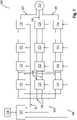
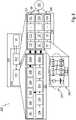
1 zeigt schematisch ein Blockdiagramm mit Kommunikationspfaden zwischen einem zentralen Kontroller und jeweiligen Modulen in einer Ausgestaltung des erfindungsgemäßen Traktionssystems.2 zeigt schematisch ein Blockdiagramm mit Komponenten des zentralen Kontrollers zu der Ausgestaltung des erfindungsgemäßen Traktionssystems.
1 FIG. 12 schematically shows a block diagram with communication paths between a central controller and respective modules in an embodiment of the traction system according to the invention.2 shows schematically a block diagram with components of the central controller for the embodiment of the traction system according to the invention.
In
In
ZITATE ENTHALTEN IN DER BESCHREIBUNGQUOTES INCLUDED IN DESCRIPTION
Diese Liste der vom Anmelder aufgeführten Dokumente wurde automatisiert erzeugt und ist ausschließlich zur besseren Information des Lesers aufgenommen. Die Liste ist nicht Bestandteil der deutschen Patent- bzw. Gebrauchsmusteranmeldung. Das DPMA übernimmt keinerlei Haftung für etwaige Fehler oder Auslassungen.This list of documents cited by the applicant was generated automatically and is included solely for the better information of the reader. The list is not part of the German patent or utility model application. The DPMA assumes no liability for any errors or omissions.
Zitierte PatentliteraturPatent Literature Cited
- US 2018/0109202 [0002]US2018/0109202 [0002]
- US 2014/0111123 A1 [0003]US 2014/0111123 A1 [0003]
- US 2019/0288617 A1 [0004]US 2019/0288617 A1 [0004]
- US 2016164399 [0005]US2016164399 [0005]
Claims (9)
Translated fromGermanPriority Applications (1)
| Application Number | Priority Date | Filing Date | Title |
|---|---|---|---|
| DE102020129128.0ADE102020129128A1 (en) | 2020-11-05 | 2020-11-05 | Distributed real-time system using a modular multilevel converter |
Applications Claiming Priority (1)
| Application Number | Priority Date | Filing Date | Title |
|---|---|---|---|
| DE102020129128.0ADE102020129128A1 (en) | 2020-11-05 | 2020-11-05 | Distributed real-time system using a modular multilevel converter |
Publications (1)
| Publication Number | Publication Date |
|---|---|
| DE102020129128A1true DE102020129128A1 (en) | 2022-05-05 |
Family
ID=81184412
Family Applications (1)
| Application Number | Title | Priority Date | Filing Date |
|---|---|---|---|
| DE102020129128.0APendingDE102020129128A1 (en) | 2020-11-05 | 2020-11-05 | Distributed real-time system using a modular multilevel converter |
Country Status (1)
| Country | Link |
|---|---|
| DE (1) | DE102020129128A1 (en) |
Cited By (4)
| Publication number | Priority date | Publication date | Assignee | Title |
|---|---|---|---|---|
| DE102023122525B3 (en) | 2023-08-23 | 2024-11-28 | Dr. Ing. H.C. F. Porsche Aktiengesellschaft | Method and system for intermodule communication in a modular battery |
| DE102023121020A1 (en) | 2023-08-08 | 2025-02-13 | Dr. Ing. H.C. F. Porsche Aktiengesellschaft | Method and device for cross-module interconnection control in a modular battery |
| DE102023124572A1 (en) | 2023-09-12 | 2025-03-13 | Dr. Ing. H.C. F. Porsche Aktiengesellschaft | Method and communication system for synchronous switching in a modular battery |
| EP4572120A1 (en)* | 2023-12-15 | 2025-06-18 | Rimac Technology LLC | Multilevel converter and method for controlling a multilevel converter |
Citations (5)
| Publication number | Priority date | Publication date | Assignee | Title |
|---|---|---|---|---|
| US20140111123A1 (en) | 2011-05-06 | 2014-04-24 | Samsung Sdi Co., Ltd. | Drive Unit for an Electric Motor |
| US20160164399A1 (en) | 2013-07-08 | 2016-06-09 | Siemens Aktiengesellschaft | Multilevel converter for power factor correction and associated operating method |
| US20180109202A1 (en) | 2015-04-02 | 2018-04-19 | Rainer Marquardt | Low-loss modular multilevel converter |
| US20190288617A1 (en) | 2018-03-19 | 2019-09-19 | Dr. Ing. H.C. F. Porsche Aktiengesellschaft | Configuration of a battery of a vehicle having a plurality of drive units |
| DE102018125728B3 (en) | 2018-10-17 | 2020-02-27 | Dr. Ing. H.C. F. Porsche Aktiengesellschaft | Method and system for parallel switching table optimization for multilevel converters |
- 2020
- 2020-11-05DEDE102020129128.0Apatent/DE102020129128A1/enactivePending
Patent Citations (5)
| Publication number | Priority date | Publication date | Assignee | Title |
|---|---|---|---|---|
| US20140111123A1 (en) | 2011-05-06 | 2014-04-24 | Samsung Sdi Co., Ltd. | Drive Unit for an Electric Motor |
| US20160164399A1 (en) | 2013-07-08 | 2016-06-09 | Siemens Aktiengesellschaft | Multilevel converter for power factor correction and associated operating method |
| US20180109202A1 (en) | 2015-04-02 | 2018-04-19 | Rainer Marquardt | Low-loss modular multilevel converter |
| US20190288617A1 (en) | 2018-03-19 | 2019-09-19 | Dr. Ing. H.C. F. Porsche Aktiengesellschaft | Configuration of a battery of a vehicle having a plurality of drive units |
| DE102018125728B3 (en) | 2018-10-17 | 2020-02-27 | Dr. Ing. H.C. F. Porsche Aktiengesellschaft | Method and system for parallel switching table optimization for multilevel converters |
Non-Patent Citations (1)
| Title |
|---|
| GALEK, M.; BLUM, M.; MLAYEH, H.: A fault tolerant communication interface for modular and distributed power electronics. In: PCIM Europe 2015; International Exhibition and Conference for Power Electronics, Intelligent Motion, Renewable Energy and Energy Management; Proceedings of, 2015, 1-8. |
Cited By (4)
| Publication number | Priority date | Publication date | Assignee | Title |
|---|---|---|---|---|
| DE102023121020A1 (en) | 2023-08-08 | 2025-02-13 | Dr. Ing. H.C. F. Porsche Aktiengesellschaft | Method and device for cross-module interconnection control in a modular battery |
| DE102023122525B3 (en) | 2023-08-23 | 2024-11-28 | Dr. Ing. H.C. F. Porsche Aktiengesellschaft | Method and system for intermodule communication in a modular battery |
| DE102023124572A1 (en) | 2023-09-12 | 2025-03-13 | Dr. Ing. H.C. F. Porsche Aktiengesellschaft | Method and communication system for synchronous switching in a modular battery |
| EP4572120A1 (en)* | 2023-12-15 | 2025-06-18 | Rimac Technology LLC | Multilevel converter and method for controlling a multilevel converter |
Similar Documents
| Publication | Publication Date | Title |
|---|---|---|
| DE102020129128A1 (en) | Distributed real-time system using a modular multilevel converter | |
| DE102018106308B4 (en) | Modulation index improvement through intelligent battery | |
| EP3521099B1 (en) | Charging system with at least one charging column for electric vehicles and method for charging one or more electric vehicles | |
| DE102019130741A1 (en) | Battery with a battery cell and method for its operation | |
| DE102017126704B4 (en) | Energy transfer in the zero system | |
| EP2994340B1 (en) | Operating method of charging device for single and multiphase charging of energy storage device of vehicle and charging device | |
| WO2018206201A1 (en) | Battery device having at least one module string, in which module string module units are interconnected one after the other in a row, and motor vehicle and operating method for the battery device | |
| DE102019130740A1 (en) | Battery with a battery cell and method for its operation | |
| DE102019130739A1 (en) | Battery with a battery cell and method for its operation | |
| EP2730019A1 (en) | Operating method for an inverter and network fault-tolerant inverter | |
| DE102020129130B3 (en) | Method and system for a safety concept of an AC battery | |
| EP3996229A1 (en) | Method and system for configuring an alternating current battery for ac charging | |
| DE102008026852A1 (en) | Inverter with two sources | |
| DE102021003852A1 (en) | Electric drive system for a vehicle and method for operating a corresponding electric drive system | |
| DE102017101496B4 (en) | HYBRID VEHICLE | |
| EP3503313B1 (en) | Multi-battery adapter for establishing an electrical connection between at least two traction batteries on the one hand and a drive unit of an electrical bicycle on the other | |
| WO2012038210A2 (en) | Energy supply system and method for charging at least one energy storage cell acting as energy store for a dc-voltage intermediate circuit in an energy supply system | |
| DE102020214760A1 (en) | Method for operating an energy storage system and energy storage system | |
| DE102013218679A1 (en) | drive control | |
| DE102013213266A1 (en) | Energy storage system with increased output electrical power | |
| DE102016012876A1 (en) | Electric drive system for a vehicle | |
| EP4558357A1 (en) | Vehicle and method for operating same | |
| WO2023025715A1 (en) | Circuit arrangement and method for generating an ac voltage | |
| DE102020129138A1 (en) | Method and circuit for matching an output filter of a DC intelligent energy storage system | |
| DE112013006795T5 (en) | Multi-axis driving device |
Legal Events
| Date | Code | Title | Description |
|---|---|---|---|
| R012 | Request for examination validly filed | ||
| R016 | Response to examination communication |