DE102020128017A1 - STOWABLE STEERING WHEEL FOR AUTONOMOUS VEHICLES - Google Patents
STOWABLE STEERING WHEEL FOR AUTONOMOUS VEHICLESDownload PDFInfo
- Publication number
- DE102020128017A1 DE102020128017A1DE102020128017.3ADE102020128017ADE102020128017A1DE 102020128017 A1DE102020128017 A1DE 102020128017A1DE 102020128017 ADE102020128017 ADE 102020128017ADE 102020128017 A1DE102020128017 A1DE 102020128017A1
- Authority
- DE
- Germany
- Prior art keywords
- column
- steering
- pillar
- powered
- motor
- Prior art date
- Legal status (The legal status is an assumption and is not a legal conclusion. Google has not performed a legal analysis and makes no representation as to the accuracy of the status listed.)
- Pending
Links
- 230000003068static effectEffects0.000claimsdescription45
- 101100116570Caenorhabditis elegans cup-2 geneProteins0.000description4
- 101100116572Drosophila melanogaster Der-1 geneProteins0.000description4
- 238000000034methodMethods0.000description2
- 208000012886VertigoDiseases0.000description1
- 238000010586diagramMethods0.000description1
- 238000006073displacement reactionMethods0.000description1
- 230000000694effectsEffects0.000description1
- 238000009429electrical wiringMethods0.000description1
- 239000002783friction materialSubstances0.000description1
- 239000000463materialSubstances0.000description1
- 238000012986modificationMethods0.000description1
- 230000004048modificationEffects0.000description1
- 230000000704physical effectEffects0.000description1
Images


Classifications
- G—PHYSICS
- G05—CONTROLLING; REGULATING
- G05D—SYSTEMS FOR CONTROLLING OR REGULATING NON-ELECTRIC VARIABLES
- G05D1/00—Control of position, course, altitude or attitude of land, water, air or space vehicles, e.g. using automatic pilots
- G05D1/0055—Control of position, course, altitude or attitude of land, water, air or space vehicles, e.g. using automatic pilots with safety arrangements
- G05D1/0061—Control of position, course, altitude or attitude of land, water, air or space vehicles, e.g. using automatic pilots with safety arrangements for transition from automatic pilot to manual pilot and vice versa
- B—PERFORMING OPERATIONS; TRANSPORTING
- B62—LAND VEHICLES FOR TRAVELLING OTHERWISE THAN ON RAILS
- B62D—MOTOR VEHICLES; TRAILERS
- B62D1/00—Steering controls, i.e. means for initiating a change of direction of the vehicle
- B62D1/02—Steering controls, i.e. means for initiating a change of direction of the vehicle vehicle-mounted
- B62D1/04—Hand wheels
- B—PERFORMING OPERATIONS; TRANSPORTING
- B62—LAND VEHICLES FOR TRAVELLING OTHERWISE THAN ON RAILS
- B62D—MOTOR VEHICLES; TRAILERS
- B62D1/00—Steering controls, i.e. means for initiating a change of direction of the vehicle
- B62D1/02—Steering controls, i.e. means for initiating a change of direction of the vehicle vehicle-mounted
- B62D1/16—Steering columns
- B62D1/18—Steering columns yieldable or adjustable, e.g. tiltable
- B62D1/181—Steering columns yieldable or adjustable, e.g. tiltable with power actuated adjustment, e.g. with position memory
- B—PERFORMING OPERATIONS; TRANSPORTING
- B62—LAND VEHICLES FOR TRAVELLING OTHERWISE THAN ON RAILS
- B62D—MOTOR VEHICLES; TRAILERS
- B62D1/00—Steering controls, i.e. means for initiating a change of direction of the vehicle
- B62D1/02—Steering controls, i.e. means for initiating a change of direction of the vehicle vehicle-mounted
- B62D1/16—Steering columns
- B62D1/18—Steering columns yieldable or adjustable, e.g. tiltable
- B62D1/183—Steering columns yieldable or adjustable, e.g. tiltable adjustable between in-use and out-of-use positions, e.g. to improve access
- B—PERFORMING OPERATIONS; TRANSPORTING
- B62—LAND VEHICLES FOR TRAVELLING OTHERWISE THAN ON RAILS
- B62D—MOTOR VEHICLES; TRAILERS
- B62D1/00—Steering controls, i.e. means for initiating a change of direction of the vehicle
- B62D1/02—Steering controls, i.e. means for initiating a change of direction of the vehicle vehicle-mounted
- B62D1/16—Steering columns
- B62D1/18—Steering columns yieldable or adjustable, e.g. tiltable
- B62D1/184—Mechanisms for locking columns at selected positions
- B—PERFORMING OPERATIONS; TRANSPORTING
- B62—LAND VEHICLES FOR TRAVELLING OTHERWISE THAN ON RAILS
- B62D—MOTOR VEHICLES; TRAILERS
- B62D1/00—Steering controls, i.e. means for initiating a change of direction of the vehicle
- B62D1/02—Steering controls, i.e. means for initiating a change of direction of the vehicle vehicle-mounted
- B62D1/16—Steering columns
- B62D1/18—Steering columns yieldable or adjustable, e.g. tiltable
- B62D1/185—Steering columns yieldable or adjustable, e.g. tiltable adjustable by axial displacement, e.g. telescopically
- B—PERFORMING OPERATIONS; TRANSPORTING
- B62—LAND VEHICLES FOR TRAVELLING OTHERWISE THAN ON RAILS
- B62D—MOTOR VEHICLES; TRAILERS
- B62D15/00—Steering not otherwise provided for
- B62D15/02—Steering position indicators ; Steering position determination; Steering aids
- B62D15/021—Determination of steering angle
- B62D15/0215—Determination of steering angle by measuring on the steering column
- B—PERFORMING OPERATIONS; TRANSPORTING
- B62—LAND VEHICLES FOR TRAVELLING OTHERWISE THAN ON RAILS
- B62D—MOTOR VEHICLES; TRAILERS
- B62D5/00—Power-assisted or power-driven steering
- B62D5/001—Mechanical components or aspects of steer-by-wire systems, not otherwise provided for in this maingroup
- B62D5/005—Mechanical components or aspects of steer-by-wire systems, not otherwise provided for in this maingroup means for generating torque on steering wheel or input member, e.g. feedback
- B62D5/006—Mechanical components or aspects of steer-by-wire systems, not otherwise provided for in this maingroup means for generating torque on steering wheel or input member, e.g. feedback power actuated
- B—PERFORMING OPERATIONS; TRANSPORTING
- B62—LAND VEHICLES FOR TRAVELLING OTHERWISE THAN ON RAILS
- B62D—MOTOR VEHICLES; TRAILERS
- B62D5/00—Power-assisted or power-driven steering
- B62D5/04—Power-assisted or power-driven steering electrical, e.g. using an electric servo-motor connected to, or forming part of, the steering gear
- B62D5/0409—Electric motor acting on the steering column
Landscapes
- Engineering & Computer Science (AREA)
- Chemical & Material Sciences (AREA)
- Combustion & Propulsion (AREA)
- Transportation (AREA)
- Mechanical Engineering (AREA)
- Radar, Positioning & Navigation (AREA)
- Aviation & Aerospace Engineering (AREA)
- Remote Sensing (AREA)
- Physics & Mathematics (AREA)
- General Physics & Mathematics (AREA)
- Automation & Control Theory (AREA)
- Steering Controls (AREA)
- Steering Control In Accordance With Driving Conditions (AREA)
Abstract
Translated fromGermanDescription
Translated fromGermanGEBIET DER ERFINDUNGFIELD OF THE INVENTION
Die vorliegende Erfindung betrifft im Allgemeinen eine verstaubare Lenksäule für Kraftfahrzeuge und insbesondere eine verstaubare Lenksäule für autonome Fahrzeuge.The present invention relates generally to a stowable steering column for automobiles, and more particularly to a stowable steering column for autonomous vehicles.
ALLGEMEINER STAND DER TECHNIKGENERAL STATE OF THE ART
Verschiedene Arten von verstaubaren Lenkrädern wurden bisher entwickelt. Im Allgemeinen bewegen sich verstaubare Lenkräder zwischen einer Einsatzposition und einer verstauten Position. Derartige Lenksysteme wurden für autonome Fahrzeuge vorgeschlagen.Various types of stowable steering wheels have heretofore been developed. In general, stowable steering wheels move between a deployed position and a stowed position. Such steering systems have been proposed for autonomous vehicles.
KURZDARSTELLUNG DER ERFINDUNGSUMMARY OF THE INVENTION
Ein Aspekt der vorliegenden Offenbarung ist eine Lenksäule für autonome Kraftfahrzeuge. Die Lenksäule beinhaltet ein statisches Element und eine drehbare untere (erste) Säule. Ein Motor nimmt die untere Säule betriebsfähig in Eingriff, wodurch die Betätigung des Motors bewirkt, dass sich die untere Säule dreht. Der Motor weist einen gesperrten Zustand auf, in dem der Motor eine Drehung der unteren Säule blockiert oder verhindert. Die Lenksäule beinhaltet einen Winkelpositionssensor, der dazu konfiguriert ist, ein Lenkbefehlssignal zu erzeugen, das einer Winkelposition der unteren Säule entspricht. Die Lenksäule beinhaltet ferner eine drehbare innere (zweite) Säule und eine drehbare obere (dritte) Säule, die bewegbar (z. B. teleskopisch) mit der unteren Säule und der inneren Säule in Eingriff tritt, wodurch die obere Säule entlang einer Achse der Lenksäule (z. B. axial) relativ zu der unteren Säule und relativ zu der inneren Säule bewegbar ist, wodurch sich die obere Säule zwischen einer eingezogenen Position und einer Einsatzposition bewegt. Die obere Säule ist relativ zu der inneren Säule durch eine Keilverzahnung oder eine andere geeignete Anordnung drehfest, wodurch sich die obere Säule und die innere Säule zusammen um die Achse der Lenksäule drehen. Die obere Säule und die untere Säule sind betriebsfähig (z. B. über Gewinde) miteinander verbunden, sodass eine Betätigung des Motors eine Drehung der unteren Säule relativ zu der oberen Säule bewirkt und eine lineare Bewegung der oberen Säule relativ zu der unteren Säule zwischen der eingezogenen Position und der Einsatzposition bewirkt. Die Lenksäule beinhaltet ferner ein Lenkrad, das an der oberen Säule befestigt ist. Die Lenksäule beinhaltet ferner eine angetriebene Arretierung, die dazu konfiguriert ist, die innere Säule an der unteren Säule zu arretieren, wenn sich die angetriebene Arretierung in einer ersten Position befindet. Die angetriebene Arretierung ist dazu konfiguriert, die innere Säule an dem statischen Element zu arretieren, wenn sich die angetriebene Arretierung in einer zweiten Position befindet. Die Lenksäule definiert: 1) eine autonome Konfiguration, in der sich die obere Säule und das Lenkrad in der verstauten Position befinden, sich die angetriebene Arretierung in der ersten Position befindet und sich der Motor in einem gesperrten Zustand befindet, um eine Drehung der unteren Säule zu verhindern, und: 2) eine manuelle Lenkkonfiguration, in der sich die obere Säule in der Einsatzposition befindet und sich die angetriebene Arretierung in der zweiten Position befindet, um eine Drehung der inneren Säule relativ zu dem statischen Element zu verhindern. Der Sensor ist dazu konfiguriert, ein Lenkbefehlssignal zu erzeugen, das einer Winkelposition der unteren Säule, der oberen Säule und des Lenkrads entspricht, wenn sich die Lenksäule in der manuellen Lenkkonfiguration befindet.One aspect of the present disclosure is a steering column for autonomous vehicles. The steering column includes a static element and a rotatable lower (first) column. A motor operably engages the lower column, whereby actuation of the motor causes the lower column to rotate. The motor has a locked state in which the motor blocks or prevents rotation of the lower column. The steering column includes an angular position sensor configured to generate a steering command signal corresponding to an angular position of the lower column. The steering column further includes a rotatable inner (second) column and a rotatable upper (third) column that movably (e.g. telescopically) engages the lower column and the inner column, thereby placing the upper column along an axis of the steering column is movable (e.g. axially) relative to the lower column and relative to the inner column, whereby the upper column moves between a retracted position and an deployed position. The upper pillar is rotatably fixed relative to the inner pillar by a spline or other suitable arrangement, whereby the upper pillar and the inner pillar rotate together about the axis of the steering column. The upper column and lower column are operably connected (e.g., by threads) so that actuation of the motor causes rotation of the lower column relative to the upper column and linear movement of the upper column relative to the lower column between the retracted position and the deployment position causes. The steering column also includes a steering wheel attached to the upper column. The steering column further includes a powered lock configured to lock the inner column to the lower column when the powered lock is in a first position. The powered lock is configured to lock the inner column to the static member when the powered lock is in a second position. The steering column defines: 1) an autonomous configuration in which the upper column and steering wheel are in the stowed position, the powered detent is in the first position, and the motor is in a locked state to allow rotation of the lower column and: 2) a manual steering configuration with the top post in the deployed position and the powered detent in the second Position is to prevent rotation of the inner column relative to the static element. The sensor is configured to generate a steering command signal corresponding to an angular position of the lower pillar, the upper pillar, and the steering wheel when the steering column is in the manual steering configuration.
Ausführungsformen des ersten Aspekts der Offenbarung können ein beliebiges oder eine Kombination der folgenden Merkmale beinhalten:
- • Die innere Säule kann drehbar mit dem statischen Element verbunden sein.
- • Die innere Säule kann eine Welle beinhalten, die sich durch eine Öffnung in der unteren Säule erstreckt.
- • Die untere Säule kann nach außen gewandte Zahnradzähne beinhalten.
- • Der Motor kann eine rotierende Ausgangswelle mit einem an der Ausgangswelle montierten Antriebszahnrad beinhalten.
- • Das Antriebszahnrad kann die nach außen gewandten Zahnradzähne der unteren Säule in Eingriff nehmen, wodurch sich die Ausgangswelle dreht, wenn der Motor betätigt wird, um dadurch die untere Säule zu drehen.
- • Der Winkelpositionssensor kann mit der Ausgangswelle des Motors wirkverbunden sein, wodurch der Winkelpositionssensor ein Signal erzeugt, das einer Winkelposition der Ausgangswelle entspricht.
- • Die innere Säule kann nach außen gewandte Zahnradzähne beinhalten.
- • Die angetriebene Arretierung kann ein Arretierungselement beinhalten, das gleichzeitig die nach außen gewandten Zahnradzähne der unteren Säule und die nach außen gewandten Zahnradzähne der inneren Säule in Eingriff nimmt, wenn sich die angetriebene Arretierung in der ersten Position befindet, um die untere Säule drehbar an der inneren Säule zu arretieren.
- • Das Arretierungselement kann gleichzeitig die nach außen gewandten Zahnradzähne der inneren Säule und eine Arretierungsfläche des statischen Elements in Eingriff nehmen, wenn sich die angetriebene Arretierung in der zweiten Position befindet, um eine Drehung der inneren Säule relativ zu dem statischen Element zu verhindern.
- • Die angetriebene Arretierung kann einen linearen Elektromagneten umfassen, der das Arretierungselement zwischen der ersten und der zweiten Position verschiebt, wenn die angetriebene Arretierung betätigt wird.
- • Die Welle der inneren Säule kann einen ersten Keilabschnitt beinhalten, der axial und verschiebbar in einen entsprechenden zweiten Keilabschnitt der oberen Säule eingreift, wodurch: 1) die innere Säule und die obere Säule relativ zueinander drehfest sind und: 2) die innere Säule und die zweite Säule axial relativ zueinander teleskopieren.
- • The inner column can be rotatably connected to the static element.
- The inner column can include a shaft that extends through an opening in the lower column.
- • The lower pillar may contain outward facing gear teeth.
- • The motor may include a rotating output shaft with a drive gear mounted on the output shaft.
- • The drive gear can engage the outwardly facing gear teeth of the lower pillar, causing the output shaft to rotate when the motor is operated to thereby rotate the lower pillar.
- • The angular position sensor can be operatively connected to the output shaft of the motor, whereby the angular position sensor generates a signal which corresponds to an angular position of the output shaft.
- • The inner pillar can include outward facing gear teeth.
- The powered detent may include a detent that simultaneously engages the outward facing gear teeth of the lower column and the outward facing gear teeth of the inner column when the powered detent is in the first position, rotatable about the lower column to lock the inner column.
- The locking element can simultaneously engage the outwardly facing gear teeth of the inner column and a locking surface of the static element when the powered lock is in the second position to prevent rotation of the inner column relative to the static element.
- The powered detent may comprise a linear solenoid that moves the detent element between the first and second positions when the powered detent is actuated.
- The shaft of the inner pillar may include a first wedge portion that axially and slidably engages a corresponding second wedge portion of the upper pillar whereby: 1) the inner pillar and the upper pillar are rotationally fixed relative to one another; and: 2) the inner pillar and the telescope the second column axially relative to one another.
Ein weiterer Aspekt der vorliegenden Offenbarung ist ein autonomes Fahrzeug, das ein Steuersystem beinhaltet, das dazu konfiguriert ist, Lenkbefehle zu erzeugen, wenn sich das autonome Fahrzeug in einem autonomen Betriebsmodus befindet. Das Steuersystem ist dazu konfiguriert, Lenkbefehle von einem Fahrzeugführer zu nutzen, wenn sich das autonome Fahrzeug in einem manuellen Betriebsmodus befindet. Das autonome Fahrzeug beinhaltet eine Lenksäule, die ein statisches Element und eine drehbare erste Säule aufweist. Die Lenksäule beinhaltet ferner einen Motor, der mit dem Steuersystem wirkverbunden ist, wobei der Motor die erste Säule mechanisch in Eingriff nimmt, sodass eine Betätigung des Motors bewirkt, dass sich die erste Säule dreht. Ein Winkelpositionssensor ist dazu konfiguriert, ein Lenkbefehlssignal an das Steuersystem zu erzeugen, das einer Winkelposition der ersten Säule entspricht, wenn sich das autonome Fahrzeug im manuellen Betriebsmodus befindet. Die Lenksäule beinhaltet ferner eine drehbare zweite Säule und eine drehbare dritte Säule. Die dritte Säule ist bewegbar an die erste Säule und die zweite Säule gekoppelt, wodurch die dritte Säule entlang einer Achse der Lenksäule relativ zu der ersten Säule und der zweiten Säule zwischen einer eingezogenen Position und einer Einsatzposition bewegbar ist. Die dritte Säule ist relativ zu der zweiten Säule drehfest, wodurch sich die dritte Säule und die zweite Säule zusammen drehen. Die dritte Säule und die erste Säule sind betriebsfähig miteinander verbunden, sodass eine Betätigung des Motors eine Drehung der ersten Säule relativ zu der dritten Säule bewirkt und eine axiale Bewegung der dritten Säule relativ zu der ersten Säule zwischen der eingezogenen Position und der Einsatzposition bewirkt. Die dritte Säule beinhaltet ein manuelles Lenkeingabeelement, wie etwa ein Lenkrad. Die Lenksäule beinhaltet ferner eine angetriebene Arretierung, die dazu konfiguriert ist, die zweite Säule an der ersten Säule zu arretieren, wenn sich die angetriebene Arretierung in einer ersten Position befindet. Die angetriebene Arretierung ist dazu konfiguriert, die zweite Säule an dem statischen Element zu arretieren, wenn sich die angetriebene Arretierung in einer zweiten Position befindet. Die Lenksäule definiert: 1) eine autonome Konfiguration, in der sich die dritte Säule in der verstauten Position befindet, sich die angetriebene Arretierung in der ersten Position befindet und der Motor eine Drehung der ersten Säule verhindert, und: 2) eine manuelle Lenkkonfiguration, in der sich die dritte Säule in der Einsatzposition befindet und sich die angetriebene Arretierung in der zweiten Position befindet, um eine Drehung der zweiten Säule relativ zu dem statischen Element zu verhindern. Der Sensor ist dazu konfiguriert, ein Lenkbefehlssignal zu erzeugen, das einer Winkelposition der ersten Säule, der dritten Säule und des manuellen Lenkeingabeelements entspricht. Das Steuersystem ist dazu konfiguriert, den Motor und die angetriebene Arretierung zu betätigen, um die Lenksäule zwischen der autonomen Konfiguration und der manuellen Lenkkonfiguration zu verschieben.Another aspect of the present disclosure is an autonomous vehicle that includes a control system configured to generate steering commands when the autonomous vehicle is in an autonomous operating mode. The control system is configured to utilize steering commands from a vehicle operator when the autonomous vehicle is in a manual operating mode. The autonomous vehicle includes a steering column that has a static member and a rotatable first column. The steering column further includes a motor operatively connected to the control system, the motor mechanically engaging the first column such that actuation of the motor causes the first column to rotate. An angular position sensor is configured to generate a steering command signal to the control system that corresponds to an angular position of the first column when the autonomous vehicle is in the manual operating mode. The steering column further includes a rotatable second column and a rotatable third column. The third column is movably coupled to the first column and the second column, whereby the third column is movable along an axis of the steering column relative to the first column and the second column between a retracted position and a deployed position. The third column is non-rotatable relative to the second column, whereby the third column and the second column rotate together. The third column and the first column are operably connected so that actuation of the motor causes the first column to rotate relative to the third column and to cause axial movement of the third column relative to the first column between the retracted position and the deployed position. The third pillar includes a manual steering input element such as a steering wheel. The steering column further includes a powered lock configured to lock the second column to the first column when the powered lock is in a first position. The powered lock is configured to lock the second column to the static member when the powered lock is in a second position. The steering column defines: 1) an autonomous configuration in which the third column is in the stowed position, the powered detent is in the first position and the motor prevents rotation of the first column, and: 2) a manual steering configuration, in which the third column is in the deployment position and the driven one Lock is in the second position to prevent rotation of the second column relative to the static element. The sensor is configured to generate a steering command signal corresponding to an angular position of the first pillar, the third pillar, and the manual steering input element. The control system is configured to operate the motor and the powered lock to shift the steering column between the autonomous configuration and the manual steering configuration.
Ausführungsformen des zweiten Aspekts der Offenbarung können ein beliebiges oder eine Kombination der folgenden Merkmale beinhalten:
- • Die erste und dritte Säule können durch Gewinde miteinander verbunden sein.
- • Die zweite Säule kann eine Welle beinhalten, die sich durch eine Öffnung in der ersten Säule erstreckt, um die zweite Säule und die erste Säule drehbar miteinander zu verbinden.
- • Die erste und zweite Säule können nach außen gewandte Zahnradzähne beinhalten.
- • Der Motor kann eine drehende Ausgangswelle mit einem an der Ausgangswelle montierten Antriebszahnrad beinhalten, wobei das Antriebszahnrad die nach außen gewandten Zahnradzähne der ersten Säule in Eingriff nimmt, wodurch eine Betätigung des Motors die untere Säule dreht.
- • Die angetriebene Arretierung kann ein Arretierungselement beinhalten, das gleichzeitig die nach außen gewandten Zahnradzähne der ersten Säule und die nach außen gewandten Zahnradzähne der zweiten Säule in Eingriff nimmt, wenn sich die angetriebene Arretierung in der ersten Position befindet, um die erste Säule drehbar an der zweiten Säule zu arretieren.
- • Der Winkelpositionssensor kann mit der Ausgangswelle des Motors wirkverbunden sein, wodurch der Winkelpositionssensor ein Signal an das Steuersystem erzeugt, das einer Winkelposition der Ausgangswelle entspricht.
- • Das Arretierungselement kann dazu konfiguriert sein, gleichzeitig die nach außen gewandten Zahnradzähne der zweiten Säule und eine Arretierungsfläche des statischen Elements in Eingriff zu nehmen, wenn sich die angetriebene Arretierung in der zweiten Position befindet, um eine Drehung der zweiten Säule relativ zu dem statischen Element zu verhindern.
- • Die angetriebene Arretierung kann einen linearen Elektromagneten umfassen, der das Arretierungselement zwischen der ersten und der zweiten Position verschiebt, wenn die angetriebene Arretierung betätigt wird.
- • Die erste Säule kann eine untere Säule umfassen.
- • Die zweite Säule kann eine innere Säule umfassen.
- • Die dritte Säule kann eine obere Säule umfassen.
- • Das manuelle Lenkeingabeelement kann ein Lenkrad umfassen.
- • Die innere Säule kann zumindest teilweise innerhalb der unteren Säule und der oberen Säule angeordnet sein.
- • Die obere Säule kann die innere Säule und die untere Säule teleskopisch in Eingriff nehmen.
- • Die obere Säule kann sich bei einer Betätigung des Motors linear entlang der Achse der Lenksäule verlagern.
- • The first and third columns can be connected to each other by threads.
- The second column may include a shaft that extends through an opening in the first column to rotatably connect the second column and the first column together.
- • The first and second columns can include outward facing gear teeth.
- The motor may include a rotating output shaft with a drive gear mounted on the output shaft, the drive gear engaging the outwardly facing gear teeth of the first column, whereby actuation of the motor rotates the lower column.
- The powered detent may include a detent that simultaneously engages the outwardly facing gear teeth of the first column and the outwardly facing gear teeth of the second column when the powered detent is in the first position, rotatable about the first column to lock the second column.
- The angular position sensor can be operatively connected to the output shaft of the motor, whereby the angular position sensor generates a signal to the control system which corresponds to an angular position of the output shaft.
- The locking element can be configured to simultaneously engage the outwardly facing gear teeth of the second column and a locking surface of the static element when the powered detent is in the second position to rotate the second column relative to the static element to prevent.
- The powered detent may comprise a linear solenoid that moves the detent element between the first and second positions when the powered detent is actuated.
- • The first column can comprise a lower column.
- • The second column can comprise an inner column.
- • The third pillar can include a top pillar.
- The manual steering input element can comprise a steering wheel.
- • The inner column can be arranged at least partially within the lower column and the upper column.
- • The upper column can telescopically engage the inner column and the lower column.
- • The upper column can move linearly along the axis of the steering column when the motor is operated.
Ein weiterer Aspekt der vorliegenden Offenbarung ist eine Lenksäule für autonome Kraftfahrzeuge, die ein statisches Element und eine drehbare untere (erste) Säule beinhaltet. Die Lenksäule beinhaltet ferner einen Motor, der dazu konfiguriert ist, die untere Säule zu drehen. Die Lenksäule beinhaltet ferner eine drehbare innere (zweite) Säule und eine drehbare obere (dritte) Säule, die mit der unteren Säule und der inneren Säule wirkverbunden ist und axial entlang einer Achse der Lenksäule relativ zu der unteren Säule und der inneren Säule bewegbar ist. Die obere Säule und die innere Säule drehen sich zusammen. Die obere Säule und die untere Säule sind betriebsfähig miteinander verbunden, sodass eine motorgetriebene Drehung der unteren Säule relativ zu der oberen Säule eine Ein- und Auswärtsbewegung der oberen Säule relativ zu der unteren Säule zwischen der eingezogenen Position und der Einsatzposition bewirkt. Die obere Säule kann ein Lenkrad beinhalten. Die Lenksäule beinhaltet ferner eine Arretierung, die dazu konfiguriert ist, die innere Säule an der unteren Säule zu arretieren, wenn sich die Arretierung in einer ersten Position befindet. Die Arretierung ist dazu konfiguriert, die innere Säule an dem statischen Element zu arretieren, wenn sich die Arretierung in einer zweiten Position befindet. Die Lenksäule definiert: 1) eine autonome Konfiguration, in der sich die obere Säule und das Lenkrad in der verstauten Position befinden, sich die Arretierung in der ersten Position befindet und der Motor abgeschaltet ist, um eine Drehung der unteren Säule zu verhindern oder zu blockieren, und: 2) eine manuelle Lenkkonfiguration, in der sich die obere Säule und das Lenkrad in der Einsatzposition befinden und sich die Arretierung in der zweiten Position befindet, um eine Drehung der inneren Säule relativ zu dem statischen Element zu verhindern.Another aspect of the present disclosure is a steering column for autonomous vehicles that includes a static member and a rotatable lower (first) column. The steering column also includes a motor configured to rotate the lower column. The steering column further includes a rotatable inner (second) column and a rotatable upper (third) column operatively connected to the lower column and the inner column and axially movable along an axis of the steering column relative to the lower column and the inner column. The top pillar and the inner pillar rotate together. The upper pillar and lower pillar are operably interconnected so that motorized rotation of the lower pillar relative to the upper pillar causes the upper pillar to move in and out relative to the lower pillar between the retracted position and the deployed position. The upper pillar can include a steering wheel. The steering column further includes a lock configured to lock the inner column to the lower column when the lock is in a first position. The lock is configured to lock the inner column to the static element when the lock is in a second position. The steering column defines: 1) an autonomous configuration in which the upper column and steering wheel are in the stowed position, the detent is in the first position, and the motor is off to prevent or block rotation of the lower column , and: 2) a manual steering configuration with the top column and steering wheel in the deployed position and the detent in the second position to prevent rotation of the inner column relative to the static member.
Ausführungsformen des dritten Aspekts der Offenbarung können ein beliebiges oder eine Kombination der folgenden Merkmale beinhalten:
- • Die Lenksäule kann optional einen Winkelpositionssensor beinhalten, der dazu konfiguriert ist, ein Lenkbefehlssignal zu erzeugen, das einer Winkelposition der unteren Säule entspricht.
- • Der Sensor kann dazu konfiguriert sein, ein Lenkbefehlssignal zu erzeugen, das einer Winkelposition der unteren Säule, der oberen Säule und des Lenkrads entspricht.
- • Die Arretierung kann einen angetriebenen Aktor und ein bewegbares Arretierungselement beinhalten, das gleichzeitig die untere Säule und die innere Säule in Eingriff nimmt, wenn sich die angetriebene Arretierung in der ersten Position befindet, um die untere Säule drehbar an der inneren Säule zu arretieren.
- The steering column can optionally include an angular position sensor configured to generate a steering command signal corresponding to an angular position of the lower column.
- The sensor can be configured to generate a steering command signal that corresponds to an angular position of the lower pillar, the upper pillar, and the steering wheel.
- The detent may include a powered actuator and a movable detent that simultaneously engages the lower column and the inner column when the powered detent is in the first position to rotatably lock the lower column to the inner column.
Diese und andere Aspekte, Aufgaben und Merkmale der vorliegenden Offenbarung sind für den Fachmann nach der Lektüre der folgenden Beschreibung, der Patentansprüche und der beigefügten Zeichnungen verständlich und nachvollziehbar.These and other aspects, objects, and features of the present disclosure will be understood and understood by those skilled in the art after reading the following description, claims, and accompanying drawings.
FigurenlisteFigure list
In den Zeichnungen gilt:
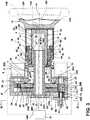
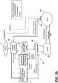
1 ist eine teilweise fragmentarische schematische Ansicht einer Lenksäule in einer verstauten/eingezogenen/autonomen Konfiguration oder einem verstauten/eingezogenen/autonomen Modus;2 ist eine teilweise fragmentarische schematische Ansicht einer Lenksäule in einer ausgefahrenen manuellen Einsatzkonfiguration oder einem ausgefahrenen manuellen Einsatzmodus;3 ist eine teilweise schematische Querschnittsansicht der Lenksäule der1 und2 in einer ausgefahrenen manuellen Einsatzkonfiguration;3A ist eine teilweise schematische Querschnittsansicht der Lenksäule der3 entlang der Linie IIIA-IIIA der 3 ;4 ist eine teilweise schematische Ansicht der Lenksäule der3 entlang der Linie IV-IV der 3 ;5 ist eine teilweise schematische Ansicht eines Abschnitts der Lenksäule der3 ;6 ist eine teilweise schematische Ansicht eines Abschnitts der Lenksäule der3 ;7 ist eine teilweise schematische Querschnittsansicht der Lenksäule der1 und 2 , die die Lenksäule in einer autonomen (eingezogenen) Konfiguration oder einem autonomen Modus zeigt;8 ist eine teilweise schematische Querschnittsansicht der Lenksäule der1 und 2 , die das Ausfahren und Einziehen der Lenksäule zeigt;9 ist eine teilweise schematische Querschnittsansicht der Lenksäule der1 und 2 , die die Lenksäule in einer manuellen (ausgefahrenen) Lenkkonfiguration oder einem manuellen Lenkmodus zeigt; und10 ist ein Blockdiagramm eines autonomen Fahrzeugs, das die Lenksäule der1-9 beinhaltet.
1 Figure 4 is a partially fragmentary schematic view of a steering column in a stowed / retracted / autonomous configuration or a stowed / retracted / autonomous mode;2 Figure 13 is a partially fragmentary schematic view of a steering column in an extended manual deployment configuration or mode;3 FIG. 13 is a partially schematic cross-sectional view of the steering column of FIG1 and2 in an extended manual deployment configuration;3A FIG. 13 is a partially schematic cross-sectional view of the steering column of FIG3 along the line IIIA-IIIA of the3 ;4th FIG. 14 is a partially schematic view of the steering column of FIG3 along the line IV-IV of the3 ;5 FIG. 13 is a partially schematic view of a portion of the steering column of FIG3 ;6th FIG. 13 is a partially schematic view of a portion of the steering column of FIG3 ;7th FIG. 13 is a partially schematic cross-sectional view of the steering column of FIG1 and2 showing the steering column in an autonomous (retracted) configuration or mode;8th FIG. 13 is a partially schematic cross-sectional view of the steering column of FIG1 and2 showing the extension and retraction of the steering column;9 FIG. 13 is a partially schematic cross-sectional view of the steering column of FIG1 and2 showing the steering column in a manual (extended) steering configuration or a manual steering mode; and10 Figure 13 is a block diagram of an autonomous vehicle that employs the steering column of the1-9 includes.
DETAILLIERTE BESCHREIBUNG DER BEVORZUGTEN AUSFÜHRUNGSFORMENDETAILED DESCRIPTION OF THE PREFERRED EMBODIMENTS
Für die Zwecke der Beschreibung in dieser Schrift beziehen sich die Ausdrücke „oberes“, „unteres“, „rechtes“, „linkes“, „hinteres“, „vorderes“, „vertikales“, „horizontales“ und Ableitungen davon auf die Offenbarung in ihrer Ausrichtung in
Unter Bezugnahme auf die
Unter weiterer Bezugnahme auf
Die Lenksäule
Unter erneuter Bezugnahme auf
Wenn sich das Arretierungselement
Der Elektromotor
Unter erneuter Bezugnahme auf
Die innere Säule
Wie vorstehend erörtert, ermöglicht die keilartige Verbindung
Innengewinde
Unter Bezugnahme auf die
Unter Bezugnahme auf
Unter weiterer Bezugnahme auf
Unter weiterer Bezugnahme auf
Unter weiterer Bezugnahme auf
Es versteht sich, dass Variationen und Modifikationen an der vorangehend erwähnten Struktur vorgenommen werden können, ohne von den Konzepten der vorliegenden Offenbarung abzuweichen, und es versteht sich ferner, dass derartige Konzepte durch die folgenden Patentansprüche abgedeckt sein sollen, sofern diese Patentansprüche durch ihren Wortlaut nicht ausdrücklich etwas anderes festlegen.It should be understood that variations and modifications can be made to the aforementioned structure without departing from the concepts of the present disclosure, and it is further understood that such concepts are intended to be covered by the following claims, unless those claims are literal expressly specify something else.
Gemäß der vorliegenden Erfindung wird eine Lenksäule für autonome Kraftfahrzeuge bereitgestellt, die Folgendes aufweist: ein statisches Element; eine drehbare untere Säule; einen Motor, der die untere Säule betriebsfähig in Eingriff nimmt, wodurch eine Betätigung des Motors bewirkt, dass sich die untere Säule dreht, und wobei der Motor einen gesperrten Zustand aufweist, in dem der Motor die Drehung der unteren Säule blockiert; einen Winkelpositionssensor, der dazu konfiguriert ist, ein Lenkbefehlssignal zu erzeugen, das einer Winkelposition der unteren Säule entspricht; eine drehbare innere Säule; eine drehbare obere Säule, die die untere Säule und die innere Säule teleskopisch in Eingriff nimmt, wodurch die obere Säule entlang einer Achse der Lenksäule relativ zu der unteren Säule und relativ zu der inneren Säule zwischen einer eingezogenen Position und einer Einsatzposition axial bewegbar ist, wobei die obere Säule relativ zu der inneren Säule drehfest ist, wodurch die obere Säule und die innere Säule zusammen um die Achse der Lenksäule drehen, und wobei die obere Säule und die untere Säule über Gewinde miteinander verbunden sind, sodass eine Betätigung des Motors eine Drehung der unteren Säule relativ zu der oberen Säule bewirkt und eine lineare Bewegung der oberen Säule relativ zu der unteren Säule zwischen der eingezogenen Position und der Einsatzposition bewirkt; ein Lenkrad, das an der oberen Säule befestigt ist; eine angetriebene Arretierung, die dazu konfiguriert ist, die innere Säule an der unteren Säule zu arretieren, wenn sich die angetriebene Arretierung in einer ersten Position befindet, und wobei die angetriebene Arretierung dazu konfiguriert ist, die innere Säule an dem statischen Element zu arretieren, wenn sich die angetriebene Arretierung in einer zweiten Position befindet, wobei die Lenksäule Folgendes definiert: 1) eine autonome Konfiguration, in der sich die obere Säule und das Lenkrad in der verstauten Position befinden, sich die angetriebene Arretierung in der ersten Position befindet und sich der Motor in einem gesperrten Zustand befindet, um eine Drehung der unteren Säule zu verhindern; und 2) eine manuelle Lenkkonfiguration, in der sich die obere Säule in der Einsatzposition befindet, sich die angetriebene Arretierung in der zweiten Position befindet, um eine Drehung der inneren Säule relativ zu dem statischen Element zu verhindern, und wobei der Sensor ein Lenkbefehlssignal erzeugt, das einer Winkelposition der unteren Säule, der oberen Säule und des Lenkrads entspricht.According to the present invention, there is provided a steering column for autonomous vehicles, comprising: a static member; a rotatable lower column; a motor operably engaging the lower pillar whereby actuation of the motor causes the lower pillar to rotate, and wherein the motor is in a locked condition in which the motor blocks rotation of the lower pillar; an angular position sensor configured to generate a steering command signal corresponding to an angular position of the lower pillar; a rotatable inner column; a rotatable upper column telescopically engaging the lower column and the inner column, whereby the upper column is axially movable along an axis of the steering column relative to the lower column and relative to the inner column between a retracted position and an deployed position, wherein the upper pillar is rotatably fixed relative to the inner pillar, whereby the upper pillar and the inner pillar rotate together about the axis of the steering column, and wherein the upper pillar and the lower pillar are connected by means of threads, so that an actuation of the motor a rotation of the causes lower column relative to upper column and causes linear movement of upper column relative to lower column between the retracted position and the deployed position; a steering wheel attached to the upper pillar; a powered lock configured to lock the inner column to the lower column when the powered lock is in a first position, and the powered lock configured to lock the inner column to the static member when the powered detent is in a second position, the steering column defining: 1) an autonomous configuration with the top column and steering wheel in the stowed position, the powered detent in the first position, and the motor is in a locked state to prevent rotation of the lower column; and 2) a manual steering configuration in which the upper column is in the deployed position, the powered detent is in the second position to prevent rotation of the inner column relative to the static member, and wherein the sensor generates a steering command signal corresponding to an angular position of the lower pillar, the upper pillar and the steering wheel.
Gemäß einer Ausführungsform ist die innere Säule drehbar mit dem statischen Element verbunden.According to one embodiment, the inner column is rotatably connected to the static element.
Gemäß einer Ausführungsform beinhaltet die innere Säule eine Welle, die sich durch eine Öffnung in der unteren Säule erstreckt.In one embodiment, the inner pillar includes a shaft that extends through an opening in the lower pillar.
Gemäß einer Ausführungsform beinhaltet die untere Säule nach außen gewandte Zahnradzähne; beinhaltet der Motor eine drehende Ausgangswelle mit einem an der Ausgangswelle montierten Antriebszahnrad, wobei das Antriebszahnrad die nach außen gewandten Zahnradzähne der unteren Säule in Eingriff nimmt, wodurch sich die Ausgangswelle dreht, wenn der Motor betätigt wird, um die untere Säule zu drehen.In one embodiment, the lower column includes outwardly facing gear teeth; the motor includes a rotating output shaft with a drive gear mounted on the output shaft, the drive gear engaging the outwardly facing gear teeth of the lower column, whereby the output shaft rotates when the motor is actuated to rotate the lower column.
Gemäß einer Ausführungsform ist der Winkelpositionssensor mit der Ausgangswelle des Motors wirkverbunden, wodurch der Winkelpositionssensor ein Signal erzeugt, das einer Winkelposition der Ausgangswelle entspricht.According to one embodiment, the angular position sensor is operatively connected to the output shaft of the motor, as a result of which the angular position sensor generates a signal which corresponds to an angular position of the output shaft.
Gemäß einer Ausführungsform beinhaltet die innere Säule nach außen gewandte Zahnradzähne; beinhaltet die angetriebene Arretierung ein Arretierungselement, das gleichzeitig die nach außen gewandten Zahnradzähne der unteren Säule und die nach außen gewandten Zahnradzähne der inneren Säule in Eingriff nimmt, wenn sich die angetriebene Arretierung in der ersten Position befindet, um die untere Säule drehbar an der inneren Säule zu arretieren.In one embodiment, the inner column includes outwardly facing gear teeth; the powered detent includes a detent that simultaneously engages the outward facing gear teeth of the lower pillar and the outward facing gear teeth of the inner pillar when the powered detent is in the first position, rotatable about the lower pillar on the inner pillar to lock.
Gemäß einer Ausführungsform nimmt das Arretierungselement gleichzeitig die nach außen gewandten Zahnradzähne der inneren Säule und eine Arretierungsfläche des statischen Elements in Eingriff, wenn sich die angetriebene Arretierung in der zweiten Position befindet, um eine Drehung der inneren Säule relativ zu dem statischen Element zu verhindern.In one embodiment, the locking element simultaneously engages the outwardly facing gear teeth of the inner column and a locking surface of the static element when the powered lock is in the second position to prevent rotation of the inner column relative to the static element.
Gemäß einer Ausführungsform umfasst die angetriebene Arretierung einen linearen Elektromagneten, der das Arretierungselement zwischen der ersten und der zweiten Position verschiebt, wenn die angetriebene Arretierung betätigt wird.According to one embodiment, the powered lock comprises a linear electromagnet which moves the locking element between the first and the second position when the powered lock is actuated.
Gemäß einer Ausführungsform beinhaltet die Welle der inneren Säule einen ersten Keilabschnitt, der axial und verschiebbar einen entsprechenden zweiten Keilabschnitt der oberen Säule in Eingriff nimmt, wodurch die innere Säule und die obere Säule relativ zueinander drehfest sind und die innere Säule und die zweite Säule axial relativ zueinander teleskopieren.In one embodiment, the shaft of the inner pillar includes a first wedge portion that axially and slidably engages a corresponding second wedge portion of the upper pillar, whereby the inner pillar and the upper pillar are rotationally fixed relative to one another and the inner pillar and the second pillar are axially relative telescope towards each other.
Gemäß der vorliegenden Erfindung wird ein autonomes Fahrzeug bereitgestellt, das Folgendes aufweist: ein Steuersystem, das dazu konfiguriert ist, Lenkbefehle zu erzeugen, wenn sich das autonome Fahrzeug in einem autonomen Betriebsmodus befindet, und wobei das Steuersystem dazu konfiguriert ist, Lenkbefehle von einem Fahrzeugführer zu nutzen, wenn sich das autonome Fahrzeug in einem manuellen Betriebsmodus befindet, eine Lenksäule, die Folgendes umfasst: ein statisches Element; eine drehbare erste Säule; einen Motor, der mit dem Steuersystem wirkverbunden ist, wobei der Motor die erste Säule mechanisch in Eingriff nimmt, wodurch eine Betätigung des Motors bewirkt, dass sich die erste Säule dreht; einen Winkelpositionssensor, der dazu konfiguriert ist, ein Lenkbefehlssignal an das Steuersystem zu erzeugen, das einer Winkelposition der ersten Säule entspricht, wenn sich das autonome Fahrzeug in dem manuellen Betriebsmodus befindet, eine drehbare zweite Säule; eine drehbare dritte Säule, die bewegbar an die erste Säule und die zweite Säule gekoppelt ist, wodurch die dritte Säule entlang einer Achse der Lenksäule relativ zu der ersten Säule und der zweiten Säule zwischen einer eingezogenen Position und einer Einsatzposition bewegbar ist, wobei die dritte Säule relativ zu der zweiten Säule drehfest ist, wodurch die dritte Säule und die zweite Säule zusammen drehen, und wobei die dritte Säule und die erste Säule betriebsfähig miteinander verbunden sind, sodass eine Betätigung des Motors eine Drehung der ersten Säule relativ zu der dritten Säule bewirkt und eine axiale Bewegung der dritten Säule relativ zu der ersten Säule zwischen der eingezogenen Position und der Einsatzposition bewirkt, wobei die dritte Säule ein manuelles Lenkeingabeelement beinhaltet; eine angetriebene Arretierung, die dazu konfiguriert ist, die zweite Säule an der ersten Säule zu arretieren, wenn sich die angetriebene Arretierung in einer ersten Position befindet, und die zweite Säule an dem statischen Element zu arretieren, wenn sich die angetriebene Arretierung in einer zweiten Position befindet, wobei die Lenksäule Folgendes definiert: 1) eine autonome Konfiguration, in der sich die dritte Säule in der verstauten Position befindet, sich die angetriebene Arretierung in der ersten Position befindet und der Motor eine Drehung der ersten Säule verhindert; und 2) eine manuelle Lenkkonfiguration, in der sich die dritte Säule in der Einsatzposition befindet, sich die angetriebene Arretierung in der zweiten Position befindet, um eine Drehung der zweiten Säule relativ zu dem statischen Element zu verhindern, und wobei der Sensor ein Lenkbefehlssignal erzeugt, das einer Winkelposition der ersten Säule, der dritten Säule und des manuellen Lenkeingabeelements entspricht; und wobei das Steuersystem dazu konfiguriert ist, den Motor und die angetriebene Arretierung zu betätigen, um die Lenksäule zwischen der autonomen Konfiguration und der manuellen Lenkkonfiguration zu verschieben.According to the present invention, there is provided an autonomous vehicle comprising: a control system configured to generate steering commands when the autonomous vehicle is in an autonomous operating mode, and wherein the control system is configured to provide steering commands from a vehicle operator when the autonomous vehicle is in a manual operating mode, utilize a steering column comprising: a static element; a rotatable first column; a motor operatively connected to the control system, the motor mechanically engaging the first column, whereby actuation of the motor causes the first column to rotate; an angular position sensor configured to generate a steering command signal to the control system corresponding to an angular position of the first column when the autonomous vehicle is in the manual operating mode, a rotatable second column; a rotatable third column movably coupled to the first column and the second column, whereby the third column is movable along an axis of the steering column relative to the first column and the second column between a retracted position and a deployed position, the third column is rotationally fixed relative to the second column, whereby the third column and the second column rotate together, and wherein the third column and the first column are operably connected to one another so that actuation of the motor causes the first column to rotate relative to the third column and causing axial movement of the third column relative to the first column between the retracted position and the deployed position, the third column including a manual steering input member; a powered lock configured to lock the second column to the first column when the powered lock is in a first position and to lock the second column to the static member when the powered lock is in a second position wherein the steering column defines: 1) an autonomous configuration in which the third column is in the stowed position, the powered detent is in the first position, and the motor prevents rotation of the first column; and 2) a manual steering configuration in which the third column is in the deployed position, the powered detent is in the second position to prevent rotation of the second column relative to the static member, and wherein the sensor generates a steering command signal, corresponding to an angular position of the first pillar, the third pillar, and the manual steering input member; and wherein the control system is configured to actuate the motor and the powered lock to shift the steering column between the autonomous configuration and the manual steering configuration.
Gemäß einer Ausführungsform sind die erste und dritte Säule durch Gewinde miteinander verbunden.According to one embodiment, the first and third columns are connected to one another by means of threads.
Gemäß einer Ausführungsform beinhaltet die zweite Säule eine Welle, die sich durch eine Öffnung in der ersten Säule erstreckt, um die zweite Säule und die erste Säule drehbar miteinander zu verbinden.In one embodiment, the second column includes a shaft that extends through an opening in the first column for rotatably connecting the second column and the first column together.
Gemäß einer Ausführungsform beinhaltet die erste Säule nach außen gewandte Zahnradzähne; beinhaltet die zweite Säule nach außen gewandte Zahnradzähne; beinhaltet der Motor eine drehende Ausgangswelle mit einem an der Ausgangswelle montierten Antriebszahnrad, wobei das Antriebszahnrad die nach außen gewandten Zahnradzähne der ersten Säule in Eingriff nimmt, wodurch sich die Ausgangswelle dreht, wenn der Motor betätigt wird, um die untere Säule zu drehen; beinhaltet die angetriebene Arretierung ein Arretierungselement, das gleichzeitig die nach außen gewandten Zahnradzähne der ersten Säule und die nach außen gewandten Zahnradzähne der zweiten Säule in Eingriff nimmt, wenn sich die angetriebene Arretierung in der ersten Position befindet, um die erste Säule drehbar an der zweiten Säule zu arreti eren.In one embodiment, the first column includes outwardly facing gear teeth; the second column includes outwardly facing gear teeth; the motor includes a rotating output shaft having a drive gear mounted on the output shaft, the drive gear engaging the outwardly facing gear teeth of the first column, thereby rotating the output shaft when the motor is actuated to rotate the lower column; the powered detent includes a detent that simultaneously engages the outwardly facing gear teeth of the first column and the outwardly facing gear teeth of the second column when the powered detent is in the first position, rotatable about the first column on the second column to lock.
Gemäß einer Ausführungsform ist der Winkelpositionssensor mit der Ausgangswelle des Motors wirkverbunden, wodurch der Winkelpositionssensor ein Signal an das Steuersystem erzeugt, das einer Winkelposition der Ausgangswelle entspricht.According to one embodiment, the angular position sensor is operatively connected to the output shaft of the motor, as a result of which the angular position sensor generates a signal to the control system which corresponds to an angular position of the output shaft.
Gemäß einer Ausführungsform nimmt das Arretierungselement gleichzeitig die nach außen gewandten Zahnradzähne der zweiten Säule und eine Arretierungsfläche des statischen Elements in Eingriff, wenn sich die angetriebene Arretierung in der zweiten Position befindet, um eine Drehung der zweiten Säule relativ zu dem statischen Element zu verhindern.In one embodiment, the locking element simultaneously engages the outwardly facing gear teeth of the second column and a locking surface of the static element when the powered lock is in the second position to prevent rotation of the second column relative to the static element.
Gemäß einer Ausführungsform umfasst die angetriebene Arretierung einen linearen Elektromagneten, der das Arretierungselement zwischen der ersten und der zweiten Position verschiebt, wenn die angetriebene Arretierung betätigt wird.According to one embodiment, the powered lock comprises a linear electromagnet which moves the locking element between the first and the second position when the powered lock is actuated.
Gemäß einer Ausführungsform umfasst die erste Säule eine untere Säule; umfasst die zweite Säule eine innere Säule; umfasst die dritte Säule eine obere Säule; umfasst das manuelle Lenkeingabeelement ein Lenkrad; und wobei die innere Säule mindestens teilweise innerhalb der unteren Säule und der oberen Säule angeordnet ist und die obere Säule die innere Säule und die untere Säule teleskopisch in Eingriff nimmt, wodurch sich die obere Säule bei Betätigung des Motors linear entlang der Achse der Lenksäule verlagert.According to one embodiment, the first column comprises a lower column; the second column includes an inner column; the third column includes an upper column; the manual steering input element comprises a steering wheel; and wherein the inner pillar is disposed at least partially within the lower pillar and the upper pillar and the upper pillar telescopically engages the inner pillar and the lower pillar, whereby the upper pillar translates linearly along the axis of the steering column when the motor is actuated.
Gemäß der vorliegenden Erfindung wird eine Lenksäule für autonome Kraftfahrzeuge bereitgestellt, die Folgendes aufweist: ein statisches Element; eine drehbare untere Säule; einen Motor, der dazu konfiguriert ist, die untere Säule zu drehen; eine drehbare innere Säule; eine drehbare obere Säule, die betriebsfähig mit der unteren Säule und der inneren Säule verbunden ist und relativ zu der unteren Säule und der inneren Säule entlang einer Achse der Lenksäule axial bewegbar ist, wobei sich die obere Säule und die innere Säule zusammen drehen, und wobei die obere Säule und die innere Säule betriebsfähig miteinander verbunden sind, sodass eine motorgetriebene Drehung der unteren Säule relativ zu der oberen Säule eine Ein- und Auswärtsbewegung der oberen Säule relativ zu der unteren Säule zwischen der eingezogenen Position und der Einsatzposition bewirkt, wobei die obere Säule ein Lenkrad beinhaltet; eine Arretierung, die dazu konfiguriert ist, die innere Säule an der unteren Säule zu arretieren, wenn sich die Arretierung in einer ersten Position befindet, und wobei die Arretierung dazu konfiguriert ist, die innere Säule an dem statischen Element zu arretieren, wenn sich die Arretierung in einer zweiten Position befindet, wobei die Lenksäule Folgendes definiert: 1) eine autonome Konfiguration, in der sich die obere Säule und das Lenkrad in der verstauten Position befinden, sich die Arretierung sich in der ersten Position befindet und sich der Motor in einem gesperrten Zustand befindet, um eine Drehung der unteren Säule zu verhindern; und 2) eine manuelle Lenkkonfiguration, in der sich die obere Säule in der Einsatzposition befindet, sich die Arretierung sich in der zweiten Position befindet, um eine Drehung der inneren Säule relativ zu dem statischen Element zu verhindern.According to the present invention, there is provided a steering column for autonomous vehicles, comprising: a static member; a rotatable lower column; a motor configured to rotate the lower column; a rotatable inner column; a rotatable upper column operably connected to the lower column and inner column and axially movable relative to the lower column and inner column along an axis of the steering column, the upper column and inner column rotating together, and wherein the upper pillar and the inner pillar are operably connected so that motorized rotation of the lower pillar relative to the upper pillar causes the upper pillar to move in and out relative to the lower pillar between the retracted position and the deployed position, the upper pillar includes a steering wheel; a lock configured to lock the inner column to the lower column when the lock is in a first position, and wherein the lock is configured to lock the inner column to the static member when the lock is in place is in a second position, the steering column defining: 1) an autonomous configuration in which the top column and steering wheel are in the stowed position, the detent is in the first position, and the motor is in a locked state located to prevent the lower column from rotating; and 2) a manual steering configuration with the upper column in the deployed position, the detent in the second position to prevent rotation of the inner column relative to the static member.
Gemäß einer Ausführungsform ist die Erfindung ferner durch einen Winkelpositionssensor gekennzeichnet, der dazu konfiguriert ist, ein Lenkbefehlssignal zu erzeugen, das einer Winkelposition der unteren Säule entspricht; und wobei der Sensor ein Lenkbefehlssignal erzeugt, das einer Winkelposition der unteren Säule, der oberen Säule und des Lenkrads entspricht.In one embodiment, the invention is further characterized by an angular position sensor configured to generate a steering command signal corresponding to an angular position of the lower pillar; and wherein the sensor generates a steering command signal corresponding to an angular position of the lower pillar, the upper pillar, and the steering wheel.
Gemäß einer Ausführungsform umfasst die Arretierung einen angetriebenen Aktor und ein bewegbares Arretierungselement, das gleichzeitig die untere Säule und die innere Säule in Eingriff nimmt, wenn sich die angetriebene Arretierung in der ersten Position befindet, um die untere Säule drehbar an der inneren Säule zu arretieren.In one embodiment, the lock includes a powered actuator and a movable lock member that simultaneously engages the lower column and the inner column when the powered lock is in the first position to rotatably lock the lower column to the inner column.
Claims (14)
Translated fromGermanApplications Claiming Priority (2)
| Application Number | Priority Date | Filing Date | Title |
|---|---|---|---|
| US16/666,873 | 2019-10-29 | ||
| US16/666,873US11061401B2 (en) | 2019-10-29 | 2019-10-29 | Stowable steering wheel for autonomous vehicles |
Publications (1)
| Publication Number | Publication Date |
|---|---|
| DE102020128017A1true DE102020128017A1 (en) | 2021-04-29 |
Family
ID=75379080
Family Applications (1)
| Application Number | Title | Priority Date | Filing Date |
|---|---|---|---|
| DE102020128017.3APendingDE102020128017A1 (en) | 2019-10-29 | 2020-10-23 | STOWABLE STEERING WHEEL FOR AUTONOMOUS VEHICLES |
Country Status (3)
| Country | Link |
|---|---|
| US (1) | US11061401B2 (en) |
| CN (1) | CN112744282A (en) |
| DE (1) | DE102020128017A1 (en) |
Cited By (2)
| Publication number | Priority date | Publication date | Assignee | Title |
|---|---|---|---|---|
| DE102022114095B3 (en) | 2022-06-03 | 2023-06-07 | Schaeffler Technologies AG & Co. KG | Steering column with hollow telescopic shaft |
| WO2024126280A1 (en)* | 2022-12-14 | 2024-06-20 | Robert Bosch Gmbh | Steer-by-wire steering system for a motor vehicle |
Families Citing this family (16)
| Publication number | Priority date | Publication date | Assignee | Title |
|---|---|---|---|---|
| DE102017007841A1 (en)* | 2017-08-17 | 2019-02-21 | Leopold Kostal Gmbh & Co. Kg | motor vehicle |
| US10953912B2 (en)* | 2018-03-14 | 2021-03-23 | Ford Global Technologies, Llc | Steering wheel systems and torque feedback actuator assemblies for use in steer-by-wire vehicles |
| DE102019107577A1 (en)* | 2019-03-25 | 2020-10-01 | Zf Automotive Germany Gmbh | Steer-by-wire steering system |
| FR3098483B1 (en)* | 2019-07-12 | 2021-06-18 | Jtekt Europe Sas | Power steering system with a retractable steering column with improved recoil stroke by means of a through-inductive sensor |
| KR20210069995A (en)* | 2019-12-04 | 2021-06-14 | 현대자동차주식회사 | Device for storing steering wheel and its control method |
| JP7375565B2 (en)* | 2020-01-15 | 2023-11-08 | 株式会社ジェイテクト | steering device |
| DE102020122327B4 (en)* | 2020-08-26 | 2024-09-05 | Audi Aktiengesellschaft | Method for positioning a steering wheel of a motor vehicle in a rest and/or an easy-entry position and a motor vehicle for carrying out the method |
| KR20220074568A (en)* | 2020-11-27 | 2022-06-03 | 현대자동차주식회사 | Apparatus and method for controlling driving of vehicle |
| DE102020215761A1 (en)* | 2020-12-11 | 2022-06-15 | Thyssenkrupp Ag | Electrically adjustable steering column with safety circuit and a method of operating an electrically adjustable steering column |
| KR20220122012A (en)* | 2021-02-26 | 2022-09-02 | 현대자동차주식회사 | Foldable steering system for automobiles |
| DE102021203818A1 (en)* | 2021-04-16 | 2022-10-20 | Volkswagen Aktiengesellschaft | Method for switching between a manual and an autonomous drive and vehicle |
| US11891108B2 (en)* | 2021-11-17 | 2024-02-06 | Steering Solutions Ip Holding Corporation | Auxiliary unstowing mechanism for vehicle steering column |
| KR102586997B1 (en)* | 2021-12-08 | 2023-10-10 | 에이치엘만도 주식회사 | Electronic control steering system and driving method thereof |
| CN114572295A (en)* | 2022-02-15 | 2022-06-03 | 宜宾凯翼汽车有限公司 | Steering column assembly and vehicle |
| DE102022111084B3 (en)* | 2022-05-05 | 2023-07-06 | Dr. Ing. H.C. F. Porsche Aktiengesellschaft | Steering device for actively controlling an at least partially autonomous motor vehicle |
| EP4574627A1 (en)* | 2023-12-22 | 2025-06-25 | FERRARI S.p.A. | Steering column for road vehicles |
Family Cites Families (58)
| Publication number | Priority date | Publication date | Assignee | Title |
|---|---|---|---|---|
| US1125539A (en) | 1914-10-01 | 1915-01-19 | Morris M Horowitz | Steering-wheel. |
| US1268505A (en) | 1917-12-14 | 1918-06-04 | Antonio C Sincare | Folding steering-wheel. |
| US1416636A (en) | 1921-09-15 | 1922-05-16 | Dorris A Hanes | Foldable steering wheel |
| US1459957A (en) | 1922-01-10 | 1923-06-26 | Fredrick B Merritt | Folding steering wheel |
| BE350944A (en) | 1927-06-20 | |||
| US1847209A (en) | 1930-01-11 | 1932-03-01 | Jr Andre Bolinas | Folding steering wheel and lock |
| US2155123A (en) | 1938-04-05 | 1939-04-18 | Gerardy Robert | Folding steering wheel |
| US2326131A (en) | 1942-04-23 | 1943-08-10 | Eschelbacher Emanuel | Clear vision steering wheel |
| US3386309A (en) | 1965-11-26 | 1968-06-04 | Borg Warner | Adjustable steering mechanism |
| JPS5833569A (en) | 1981-08-21 | 1983-02-26 | Aisin Seiki Co Ltd | Controller for position on vehicle |
| JPH01111566A (en) | 1987-10-26 | 1989-04-28 | Fuji Kiko Co Ltd | electric telescopic steering device |
| FR2662986B1 (en) | 1990-06-07 | 1994-11-18 | Nacam | DEVICE FOR ADJUSTING THE POSITION OF AN ADJUSTABLE STEERING COLUMN. |
| JP3203949B2 (en) | 1994-04-28 | 2001-09-04 | 豊田合成株式会社 | Console box and manufacturing method thereof |
| DE19548717C1 (en) | 1995-12-23 | 1997-05-07 | Daimler Benz Ag | Control element arrangement for controlling the longitudinal movement and / or the transverse movement of a motor vehicle |
| FR2779695B1 (en) | 1998-06-16 | 2000-09-08 | Peugeot | DASHBOARD FOR A MOTOR VEHICLE THAT CAN BE TRANSFORMED INTO AN ACTIVITY STATION |
| DE19962494A1 (en) | 1998-12-25 | 2000-07-06 | Nsk Ltd | Automatic steering column adjusting device has steering shaft position detectors and electrical shaft angle and telescopic length actuators |
| JP3468742B2 (en) | 2000-08-18 | 2003-11-17 | 株式会社山田製作所 | Rotation support structure of tilt steering |
| WO2003020571A1 (en) | 2001-08-31 | 2003-03-13 | Johnson Controls Technology Company | Stowable steering wheel |
| US6857498B2 (en) | 2002-07-25 | 2005-02-22 | General Motors Corporation | Console with driver's interface |
| DE10245523A1 (en) | 2002-09-27 | 2004-04-08 | Continental Teves Ag & Co. Ohg | Adjustable pedal controls for automobile has holder supporting rotatable carrier within which each pedal is rotatable about a respective axis |
| DE10347925A1 (en) | 2003-10-15 | 2005-05-19 | Daimlerchrysler Ag | Automotive steering wheel has moving L-shaped link to shaft assembly for shift to vehicle centerline position |
| US7441799B2 (en) | 2003-12-08 | 2008-10-28 | Autoliv Asp, Inc. | Non-circular steering wheel assembly and airbag module |
| DE102005044289B4 (en) | 2005-09-16 | 2008-04-30 | GM Global Technology Operations, Inc., Detroit | Steering wheel for a motor vehicle |
| US20070241548A1 (en)* | 2006-04-13 | 2007-10-18 | Fong Jian J | Steering wheel retracting device for vehicle |
| US20070295151A1 (en) | 2006-05-16 | 2007-12-27 | Boris Kentor | Steering wheel having pivoting rim |
| JP5131523B2 (en) | 2007-09-10 | 2013-01-30 | 株式会社ジェイテクト | Vehicle steering system |
| JP5228003B2 (en) | 2010-07-20 | 2013-07-03 | 森六テクノロジー株式会社 | Hinge structure of vehicular storage device |
| DE102010055589A1 (en) | 2010-12-22 | 2012-06-28 | Daimler Ag | Steering wheel for motor vehicle, has rings that are moved together with spokes, into open position of steering wheel rim |
| JP6071477B2 (en) | 2012-11-29 | 2017-02-01 | しげる工業株式会社 | Vehicle console box |
| US9333983B2 (en) | 2013-03-15 | 2016-05-10 | Volkswagen Ag | Dual-state steering wheel/input device |
| US9630644B2 (en)* | 2013-03-15 | 2017-04-25 | Ford Global Technologies, Llc | Method and system for stowing steering column in an autonomous vehicle |
| US9073574B2 (en) | 2013-11-20 | 2015-07-07 | Ford Global Technologies, Llc | Autonomous vehicle with reconfigurable interior |
| US20160325662A1 (en) | 2015-05-04 | 2016-11-10 | Steering Solutions Ip Holding Corporation | Steering wheel with integral tray table |
| US9919724B2 (en) | 2015-05-29 | 2018-03-20 | Steering Solutions Ip Holding Corporation | Retractable steering column with manual retrieval |
| US10343706B2 (en)* | 2015-06-11 | 2019-07-09 | Steering Solutions Ip Holding Corporation | Retractable steering column system, vehicle having the same, and method |
| US20160375924A1 (en) | 2015-06-25 | 2016-12-29 | Steering Solutions Ip Holding Corporation | Steering wheel with integrated keyboard assembly |
| US9845103B2 (en) | 2015-06-29 | 2017-12-19 | Steering Solutions Ip Holding Corporation | Steering arrangement |
| CH711640B1 (en) | 2015-10-09 | 2019-06-28 | Rinspeed Ag | Steering device with at least one folding steering wheel segment or steering wheel lever and its use. |
| US20180304788A1 (en) | 2015-10-14 | 2018-10-25 | MOTHERSON AUTOMOTIVE TECHNOLOGIES & ENGINEERING (A Division of Motherson Sumi Systems Ltd.) | Controlled movement of the armrest |
| DE102015220526A1 (en) | 2015-10-21 | 2017-04-27 | Bayerische Motoren Werke Aktiengesellschaft | Retractable and extendable steering device for a vehicle |
| US9963035B2 (en) | 2016-02-05 | 2018-05-08 | Ford Global Technologies, Llc | Removable steering wheel and pedals for autonomous vehicle |
| CN107416008A (en)* | 2016-04-13 | 2017-12-01 | 法拉第未来公司 | The system and method for making steering wheel for vehicle retract and stretch out automatically |
| GB2550641B (en) | 2016-05-25 | 2019-11-20 | Ford Global Tech Llc | A steering wheel assembly |
| GB2550640B (en) | 2016-05-25 | 2020-03-25 | Ford Global Tech Llc | A steering wheel assembly |
| DE102016115466B4 (en) | 2016-08-19 | 2021-02-11 | Thyssenkrupp Ag | Control horn for steering a motor vehicle |
| US10442455B2 (en)* | 2016-09-19 | 2019-10-15 | Fca Us Llc | Stowable steering wheel assembly |
| FR3057533B1 (en) | 2016-10-17 | 2021-11-05 | Renault Sas | STEERING WHEEL FOR AUTONOMOUS MOTOR VEHICLE. |
| FR3057532B1 (en) | 2016-10-17 | 2019-04-12 | Renault S.A.S | FLYWHEEL FOR AUTONOMOUS MOTOR VEHICLE. |
| US10351160B2 (en)* | 2016-11-30 | 2019-07-16 | Steering Solutions Ip Holding Corporation | Steering column assembly having a sensor assembly |
| US20180154921A1 (en)* | 2016-12-06 | 2018-06-07 | Ford Global Technologies, Llc | Folding steering wheel |
| US10780915B2 (en)* | 2016-12-07 | 2020-09-22 | Steering Solutions Ip Holding Corporation | Vehicle steering system having a user experience based automated driving to manual driving transition system and method |
| FR3066462B1 (en)* | 2017-05-19 | 2019-07-19 | Faurecia Interieur Industrie | STEERING WHEEL OF A VEHICLE MOVING BETWEEN A DEPLOYED POSITION AND A RETRACTED POSITION |
| DE102017209499A1 (en) | 2017-06-06 | 2018-12-06 | Brose Fahrzeugteile Gmbh & Co. Kommanditgesellschaft, Coburg | Folding steering wheel |
| US10882548B2 (en)* | 2017-10-17 | 2021-01-05 | Steering Solutions Ip Holding Corporation | Stowable steering column apparatus |
| DE102018221992A1 (en) | 2017-12-19 | 2019-06-19 | Mando Corporation | STEERING DEVICE FOR VEHICLES |
| US11124219B2 (en)* | 2018-06-04 | 2021-09-21 | Ford Global Technologies, Llc | Stowable vehicle interface |
| GB2578777B (en) | 2018-11-08 | 2022-02-23 | Bentley Motors Ltd | Manual steering control unit for autonomous vehicle |
| US10562558B1 (en) | 2019-04-09 | 2020-02-18 | Ford Global Technologies, Llc | Foldable steering wheel system |
- 2019
- 2019-10-29USUS16/666,873patent/US11061401B2/enactiveActive
- 2020
- 2020-10-23CNCN202011144984.2Apatent/CN112744282A/enactivePending
- 2020-10-23DEDE102020128017.3Apatent/DE102020128017A1/enactivePending
Cited By (2)
| Publication number | Priority date | Publication date | Assignee | Title |
|---|---|---|---|---|
| DE102022114095B3 (en) | 2022-06-03 | 2023-06-07 | Schaeffler Technologies AG & Co. KG | Steering column with hollow telescopic shaft |
| WO2024126280A1 (en)* | 2022-12-14 | 2024-06-20 | Robert Bosch Gmbh | Steer-by-wire steering system for a motor vehicle |
Also Published As
| Publication number | Publication date |
|---|---|
| CN112744282A (en) | 2021-05-04 |
| US11061401B2 (en) | 2021-07-13 |
| US20210124349A1 (en) | 2021-04-29 |
Similar Documents
| Publication | Publication Date | Title |
|---|---|---|
| DE102020128017A1 (en) | STOWABLE STEERING WHEEL FOR AUTONOMOUS VEHICLES | |
| EP3322632B1 (en) | Feedback actuator for a steering device | |
| EP3500476B1 (en) | Control yoke for steering a motor vehicle | |
| EP4175865B1 (en) | Steering column for a motor vehicle | |
| EP1110828A2 (en) | Locking device | |
| EP4103451B1 (en) | Steering column for a motor vehicle | |
| EP2193077B1 (en) | Steering unit for a steer-by-wire ship's control system and method for operating the steering unit | |
| DE4217664A1 (en) | POWER DRIVE FOR AN ADJUSTABLE MECHANISM | |
| DE10295885T5 (en) | Permanently engaging linear mechanism | |
| EP1836421B1 (en) | Device for operating selector forks | |
| EP1870617B1 (en) | Actuating device for the transmission of a vehicle | |
| DE112020002348T5 (en) | AUTOMOTIVE STEERING DEVICE | |
| DE102019219600A1 (en) | Steering device for a motor vehicle | |
| DE112020002349T5 (en) | VEHICLE STEERING DEVICE | |
| DE69000308T2 (en) | DEVICE FOR CONTROLLING THE TILTING OF A HEADLAMP. | |
| WO2021239180A1 (en) | Drive unit for motor vehicle applications | |
| DE69107829T2 (en) | Steering lock device for a telescopic steering device. | |
| WO2024126280A1 (en) | Steer-by-wire steering system for a motor vehicle | |
| WO2020089199A1 (en) | Steering shaft for a steering column of a motor vehicle and steering column for a motor vehicle | |
| DE102019108848B3 (en) | Actuator system, rearview device, motor vehicle and adjustment method | |
| DE202014100866U1 (en) | Single-axis linear drive | |
| DE102018107762A1 (en) | linear actuator | |
| DE102013012660A1 (en) | Gear cutting machine and method for machining a toothing | |
| DE102024121574B3 (en) | Actuating device with activatable auxiliary drive | |
| DE202005001208U1 (en) | Electromotive drive device for shifting movable furniture components, has linear portable control element arranged in housing with two end switches arranged at a distance to each other and functionally cooperative with it |
Legal Events
| Date | Code | Title | Description |
|---|---|---|---|
| R082 | Change of representative | Representative=s name:ETL IP PATENTANWALTSGESELLSCHAFT MBH, DE Representative=s name:ETL IP PATENT- UND RECHTSANWALTSGESELLSCHAFT M, DE |