DE102020125632A1 - pressure sprayer - Google Patents
pressure sprayerDownload PDFInfo
- Publication number
- DE102020125632A1 DE102020125632A1DE102020125632.9ADE102020125632ADE102020125632A1DE 102020125632 A1DE102020125632 A1DE 102020125632A1DE 102020125632 ADE102020125632 ADE 102020125632ADE 102020125632 A1DE102020125632 A1DE 102020125632A1
- Authority
- DE
- Germany
- Prior art keywords
- pressure
- pump
- container
- sprayer
- bar
- Prior art date
- Legal status (The legal status is an assumption and is not a legal conclusion. Google has not performed a legal analysis and makes no representation as to the accuracy of the status listed.)
- Pending
Links
- 239000007921spraySubstances0.000claimsabstractdescription45
- 210000002445nippleAnatomy0.000claimsdescription9
- 239000007788liquidSubstances0.000description15
- 239000006260foamSubstances0.000description9
- 229910001416lithium ionInorganic materials0.000description8
- 239000003795chemical substances by applicationSubstances0.000description7
- HBBGRARXTFLTSG-UHFFFAOYSA-NLithium ionChemical compound[Li+]HBBGRARXTFLTSG-UHFFFAOYSA-N0.000description4
- 238000005086pumpingMethods0.000description4
- 241000196324EmbryophytaSpecies0.000description3
- 239000004009herbicideSubstances0.000description3
- 239000002917insecticideSubstances0.000description3
- 238000000034methodMethods0.000description3
- 238000005507sprayingMethods0.000description3
- XLYOFNOQVPJJNP-UHFFFAOYSA-NwaterSubstancesOXLYOFNOQVPJJNP-UHFFFAOYSA-N0.000description3
- 238000009736wettingMethods0.000description3
- 230000015572biosynthetic processEffects0.000description2
- 230000000903blocking effectEffects0.000description2
- 229920001971elastomerPolymers0.000description2
- 238000009415formworkMethods0.000description2
- 239000000463materialSubstances0.000description2
- 239000003595mistSubstances0.000description2
- 238000012544monitoring processMethods0.000description2
- BASFCYQUMIYNBI-UHFFFAOYSA-NplatinumChemical compound[Pt]BASFCYQUMIYNBI-UHFFFAOYSA-N0.000description2
- 229920001296polysiloxanePolymers0.000description2
- 239000004814polyurethaneSubstances0.000description2
- 230000001681protective effectEffects0.000description2
- BUHVIAUBTBOHAG-FOYDDCNASA-N(2r,3r,4s,5r)-2-[6-[[2-(3,5-dimethoxyphenyl)-2-(2-methylphenyl)ethyl]amino]purin-9-yl]-5-(hydroxymethyl)oxolane-3,4-diolChemical compoundCOC1=CC(OC)=CC(C(CNC=2C=3N=CN(C=3N=CN=2)[C@H]2[C@@H]([C@H](O)[C@@H](CO)O2)O)C=2C(=CC=CC=2)C)=C1BUHVIAUBTBOHAG-FOYDDCNASA-N0.000description1
- 229910052782aluminiumInorganic materials0.000description1
- XAGFODPZIPBFFR-UHFFFAOYSA-NaluminiumChemical compound[Al]XAGFODPZIPBFFR-UHFFFAOYSA-N0.000description1
- 238000009530blood pressure measurementMethods0.000description1
- 238000004140cleaningMethods0.000description1
- 238000007906compressionMethods0.000description1
- 230000000694effectsEffects0.000description1
- 239000000806elastomerSubstances0.000description1
- 238000005187foamingMethods0.000description1
- 230000017525heat dissipationEffects0.000description1
- 238000001746injection mouldingMethods0.000description1
- 238000009434installationMethods0.000description1
- 239000012528membraneSubstances0.000description1
- 229910052987metal hydrideInorganic materials0.000description1
- 239000007769metal materialSubstances0.000description1
- 239000004476plant protection productSubstances0.000description1
- 239000004033plasticSubstances0.000description1
- 229920003023plasticPolymers0.000description1
- 229920002635polyurethanePolymers0.000description1
- 229920000915polyvinyl chloridePolymers0.000description1
- 238000003825pressingMethods0.000description1
- 238000007789sealingMethods0.000description1
- 239000000243solutionSubstances0.000description1
Images


Classifications
- B—PERFORMING OPERATIONS; TRANSPORTING
- B05—SPRAYING OR ATOMISING IN GENERAL; APPLYING FLUENT MATERIALS TO SURFACES, IN GENERAL
- B05B—SPRAYING APPARATUS; ATOMISING APPARATUS; NOZZLES
- B05B9/00—Spraying apparatus for discharge of liquids or other fluent material, without essentially mixing with gas or vapour
- B05B9/03—Spraying apparatus for discharge of liquids or other fluent material, without essentially mixing with gas or vapour characterised by means for supplying liquid or other fluent material
- B05B9/04—Spraying apparatus for discharge of liquids or other fluent material, without essentially mixing with gas or vapour characterised by means for supplying liquid or other fluent material with pressurised or compressible container; with pump
- B05B9/08—Apparatus to be carried on or by a person, e.g. of knapsack type
- B05B9/0805—Apparatus to be carried on or by a person, e.g. of knapsack type comprising a pressurised or compressible container for liquid or other fluent material
- B—PERFORMING OPERATIONS; TRANSPORTING
- B05—SPRAYING OR ATOMISING IN GENERAL; APPLYING FLUENT MATERIALS TO SURFACES, IN GENERAL
- B05B—SPRAYING APPARATUS; ATOMISING APPARATUS; NOZZLES
- B05B12/00—Arrangements for controlling delivery; Arrangements for controlling the spray area
- B05B12/004—Arrangements for controlling delivery; Arrangements for controlling the spray area comprising sensors for monitoring the delivery, e.g. by displaying the sensed value or generating an alarm
- B05B12/006—Pressure or flow rate sensors
- B05B12/008—Pressure or flow rate sensors integrated in or attached to a discharge apparatus, e.g. a spray gun
- B—PERFORMING OPERATIONS; TRANSPORTING
- B05—SPRAYING OR ATOMISING IN GENERAL; APPLYING FLUENT MATERIALS TO SURFACES, IN GENERAL
- B05B—SPRAYING APPARATUS; ATOMISING APPARATUS; NOZZLES
- B05B9/00—Spraying apparatus for discharge of liquids or other fluent material, without essentially mixing with gas or vapour
- B05B9/03—Spraying apparatus for discharge of liquids or other fluent material, without essentially mixing with gas or vapour characterised by means for supplying liquid or other fluent material
- B05B9/04—Spraying apparatus for discharge of liquids or other fluent material, without essentially mixing with gas or vapour characterised by means for supplying liquid or other fluent material with pressurised or compressible container; with pump
- B05B9/08—Apparatus to be carried on or by a person, e.g. of knapsack type
- B05B9/085—Apparatus to be carried on or by a person, e.g. of knapsack type with a liquid pump
- B05B9/0855—Apparatus to be carried on or by a person, e.g. of knapsack type with a liquid pump the pump being motor-driven
- B05B9/0861—Apparatus to be carried on or by a person, e.g. of knapsack type with a liquid pump the pump being motor-driven the motor being electric
- B—PERFORMING OPERATIONS; TRANSPORTING
- B05—SPRAYING OR ATOMISING IN GENERAL; APPLYING FLUENT MATERIALS TO SURFACES, IN GENERAL
- B05B—SPRAYING APPARATUS; ATOMISING APPARATUS; NOZZLES
- B05B9/00—Spraying apparatus for discharge of liquids or other fluent material, without essentially mixing with gas or vapour
- B05B9/03—Spraying apparatus for discharge of liquids or other fluent material, without essentially mixing with gas or vapour characterised by means for supplying liquid or other fluent material
- B05B9/04—Spraying apparatus for discharge of liquids or other fluent material, without essentially mixing with gas or vapour characterised by means for supplying liquid or other fluent material with pressurised or compressible container; with pump
- B05B9/08—Apparatus to be carried on or by a person, e.g. of knapsack type
- B05B9/0888—Carrying means for knapsack sprayers
Landscapes
- Chemical & Material Sciences (AREA)
- Analytical Chemistry (AREA)
- Physics & Mathematics (AREA)
- Fluid Mechanics (AREA)
- Nozzles (AREA)
Abstract
Translated fromGerman
Description
Translated fromGermanDie Erfindung betrifft ein Drucksprühgerät mit einem Druckbehälter, einer elektrischen Pumpe, sowie einer elektrischen Speichereinrichtung zur Energieversorgung der elektrischen Pumpe, wobei mit der elektrischen Pumpe im Innenraum des Behälters ein Behälterdruck aufgebaut wird.The invention relates to a pressure spray device with a pressure container, an electric pump and an electric storage device for supplying energy to the electric pump, with the electric pump building up a container pressure in the interior of the container.
Drucksprühgeräte für unterschiedliche Anwendungen sind aus einer Vielzahl von Druckschriften bekannt geworden.Pressure sprayers for different applications have become known from a large number of publications.
Aus der
Die
Insbesondere bei großen Volumina war dies aufwändig.This was time-consuming, especially in the case of large volumes.
Aus der
Ähnlich ist auch das Drucksprühgerät, das aus der
Ähnliche Prinzipien zeigen auch die
Alle zuvor genannten elektrischen Systeme verfügen über einen Druckschalter, der den Motor bei Erreichen eines vorgegebenen Druckes abschaltet und wieder einschaltet.All of the electrical systems mentioned above have a pressure switch that turns the motor off and on again when a predetermined pressure is reached.
Aus der
Anstelle der NiMh-Akkumulatoren wie beispielsweise in der
Nachteilig an sämtlichen Drucksprühgeräten mit elektrischen Pumpen im Stand der Technik war, dass der Austausch der Energiequellen zeitaufwändig gewesen ist und ein leichter Wechsel der Akkumulatoren nicht möglich war.A disadvantage of all pressure sprayers with electric pumps in the prior art was that replacing the energy sources was time-consuming and it was not possible to easily change the accumulators.
Ein weiterer Nachteil im Stand der Technik war, dass der Druck im Behälter unter Ausbringen der Flüssigkeit abgesunken ist. Die Druckreduzierung hatte zur Folge, dass sich der Volumenstrom der zu versprühenden Flüssigkeit geändert hat.A further disadvantage of the prior art was that the pressure in the container dropped when the liquid was dispensed. The pressure reduction meant that the volume flow of the liquid to be sprayed changed.
Aufgabe der Erfindung ist es diese und andere Nachteile des Standes der Technik zu überwinden.The object of the invention is to overcome these and other disadvantages of the prior art.
Diese Aufgabe wird durch ein Drucksprühgerät gemäß Anspruch 1 gelöst, bei dem die elektrische Speichereinrichtung, insbesondere der Akkumulator außerhalb des Innenraumes des Behälters seitlich an der Außenwand des Behälters oder seitlich an dem Tragegriff eines Einsatzes für das Drucksprühgerät angeordnet ist, wobei der Einsatz die elektrische Pumpe umfasst.This object is achieved by a pressure sprayer according to
Bevorzugt ist die Pumpe in einem Gehäuse, das Teil des Einsatzes ist, untergebracht. Ein ganz besonders leichter Austausch wird dann ermöglicht, wenn am Behälter oder am Gehäuse, das Teil des Einsatzes ist, eine Befestigungsvorrichtung, die ein Einrasten der Speichereinrichtung, insbesondere des Akkumulators ermöglicht, vorgesehen ist. Hierbei es ganz bevorzugt, wenn der Akkumulator an der Behälteraußenseite bzw. Wand des Gehäuses angeordnet ist, das die Pumpe aufnimmt. Bevorzugt kann der Akkumulator in Gleitschienen eingeschoben werden, bis die Speichereinrichtung bzw. der Akkumulator einrastet und die Spannungsversorgung über elektrische Kontakte von der eingeschobenen Speichereinrichtung bzw. Akkumulator zur Pumpe hergestellt ist.Preferably the pump is housed in a housing which is part of the insert. A very particularly easy exchange is made possible if a fastening device, which enables the storage device, in particular the accumulator, to snap into place, is provided on the container or on the housing, which is part of the insert. It is very preferred here if the accumulator is arranged on the outside of the container or on the wall of the housing which accommodates the pump. The accumulator can preferably be pushed into slide rails until the storage device or the accumulator snaps into place and the power supply is established via electrical contacts from the inserted storage device or accumulator to the pump.
Anstelle der bislang verwendeten Nickel-Metallhydrid-Zellen wie in der
Um zu gewährleisten, dass immer der für den Sprühvorgang notwendige Druck im Behälter des Drucksprühgerätes vorliegt, sind bei dem erfindungsgemäßen Drucksprühgerät Drucksensoren vorgesehen, die den Druckverlust bei ausströmender Sprühflüssigkeit im Behälter erfassen und einer Druckregelung zuleiten. Bevorzugt sind die Drucksensoren im Gehäuse des Einsatzes, das die elektrische Pumpe aufnimmt, vorgesehen. Sobald der Druckverlust, der vom Drucksensor gemessen wird, einen unteren Grenzwert erreicht, schaltet die Druckregelung die elektrische Pumpe an. Durch die Pumpe wird dann Druckluft solange in den Behälter des Drucksprühgerätes gefördert, bis ein oberer Grenzwert erreicht ist. Die Druckregelung schaltet dann die Pumpe wieder ab. Mit der ständigen Überwachung des Druckes und dem Abschalten und Anschalten der elektrischen Pumpe ist es möglich einen voreingestellten Druck im Behälter des Drucksprühgerätes aufrecht zu erhalten.In order to ensure that the pressure required for the spraying process is always present in the container of the pressure sprayer, pressure sensors are provided in the pressure sprayer according to the invention, which detect the pressure loss when the spray liquid flows out in the container and forward it to a pressure regulator. The pressure sensors are preferably provided in the housing of the insert that accommodates the electric pump. As soon as the pressure loss measured by the pressure sensor reaches a lower limit, the pressure control switches on the electric pump. Compressed air is then fed into the container of the pressure sprayer by the pump until an upper limit value is reached. The pressure control then switches the pump off again. By constantly monitoring the pressure and switching the electric pump on and off, it is possible to maintain a preset pressure in the pressure sprayer tank.
Der konstant gehaltene Druck führt dazu, dass ein konstanter Volumenstrom gewährleistet wird. Auf diese Weise kann sichergestellt werden, dass nicht unnötig viel Spritzflüssigkeit, insbesondere Pflanzenschutzmittel, in die Umwelt gelangt. Zum Anderen bestimmt der Druck auch die Tröpfchengröße des Sprühnebels. Bei zu hohem Druck sind die Tröpfchen kleiner und können somit durch Abdrift bei Wind Pflanzen kontaminieren, die gar nicht besprüht werden sollen. Zu große Tropfen, die bei niedrigem Druck entstehen, verhindern eine ausreichende Benetzung der Pflanzenblätter. Bei Insektiziden ist es vorteilhaft, wenn der Druck so eingestellt wird, dass kleine Tröpfchen vorliegen. In einem derartigen Fall wird ein feiner Nebel ausgebildet, der eine vollständige Benetzung der Blätter sicherstellt. Der Druck für das Ausbringen von Insektiziden liegt bevorzugt zwischen 2 und 2,5 bar.The constant pressure means that a constant volume flow is guaranteed. In this way it can be ensured that not an unnecessarily large amount of spray liquid, in particular plant protection products, gets into the environment. On the other hand, the pressure also determines the droplet size of the spray mist. If the pressure is too high, the droplets are smaller and can therefore contaminate plants that should not be sprayed at all by drifting in the wind. Drops that are too large, which occur at low pressure, prevent sufficient wetting of the plant leaves. In the case of insecticides, it is advantageous if the pressure is adjusted so that small droplets are present. In such a case, a fine mist is formed that ensures complete wetting of the leaves. The pressure for applying insecticides is preferably between 2 and 2.5 bar.
Bei Herbiziden ist eine größere Tröpfchengröße anzustreben, damit ein Abdriften der Tröpfchen verhindert wird. Bevorzugt liegt der Druck nicht über 1,5 bar, bevorzugt im Bereich 1 bis 2 bar, bevorzugt bei ungefähr 1,5 bar.In the case of herbicides, a larger droplet size should be aimed for, so that the droplets are prevented from drifting. The pressure is preferably not more than 1.5 bar, preferably in the range from 1 to 2 bar, preferably around 1.5 bar.
Für eine Anwendung bei der Schaumerzeugung in der Reinigung, z.B. von Kraftfahrzeugen ist ein konstanter Druck erforderlich, damit die eingestellte Schaumqualität während des Einschäumungsprozesses gleich bleibt. Um eine befriedigende Schaumqualität zur Verfügung zu stellen, liegt der Druck im Bereich 2 bis 2,5 bar, mindestens jedoch bei 2 bar, da eine Schaumbildung unterhalb von 2 bar nicht stattfindet. Für eine gleichmäßige Benetzung ist es vorteilhaft, wenn ein Druck konstant aufrecht erhalten wird.For use in foam generation in cleaning, e.g. of motor vehicles, a constant pressure is required so that the set foam quality remains the same during the foaming process. In order to provide a satisfactory foam quality, the pressure is in the range from 2 to 2.5 bar, but at least 2 bar, since foam formation below 2 bar does not take place. For uniform wetting, it is advantageous if a constant pressure is maintained.
Für das Aufbringen von Schalöl auf eine Einschalung z.B. für Beton als Trennmittel müssen abhängig von der Viskosität des Öls unterschiedliche Arbeitsdrücke eingestellt werden. Durch einen konstanten Druck kann bei einer derartigen Anwendung eine gleichmäßige benetzte Oberfläche erreicht werden.For the application of formwork oil to formwork, e.g. for concrete as a release agent, different working pressures must be set depending on the viscosity of the oil. A constant pressure can be used to achieve an evenly wetted surface in such an application.
Für den Fall, das aus dem Behälter mehr Volumen an Luft entnommen wird, als die Pumpe fördern kann, stellt sich ein Arbeitsdruck unterhalb des eingestellten Solldruckes ein und die Pumpe läuft durch.In the event that more volume of air is taken from the container than the pump can deliver, the working pressure will be below the set target pressure and the pump will run.
Bevorzugt ist die Pumpe so ausgelegt, dass für verschiedene Sprühanwendungen und Anforderungen ein ausreichender Volumenstrom in einem Druckbereich zwischen 1 und 3 bar, besonders bevorzugt zwischen 1,5 und 2,5 bar zur Verfügung gestellt wird. Insbesondere wird der Druck auf einem Bedienfeld bevorzugt einer Anzeigevorrichtung, insbesondere einem Display im Bereich 1,5 bis 2,5 bar eingestellt.The pump is preferably designed in such a way that, for various spray applications and requirements, there is a sufficient volume flow in a pressure range between 1 and 3 bar, in particular preferably between 1.5 and 2.5 bar is provided. In particular, the pressure is set on a control panel, preferably a display device, in particular a display, in the range from 1.5 to 2.5 bar.
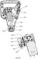
In einer ersten Ausgestaltung der Erfindung wird als elektrische Pumpe eine Pendel-Kolben-Pumpe verwendet. Bei dem Einsatz einer Pendel-Kolben-Pumpe wird die Abdichtung des Kolbens zum Zylinder mit Hilfe einer Gummimembrane erreicht. Dadurch vereint die Pendel-Kolben-Pumpe die Vorteile der Membranpumpe mit denen der Kolbenpumpe. Vorteilhafterweise ist die Pendel-Kolben-Pumpe laufruhiger als eine Kolbenpumpe und muss nicht geschmiert werden.. Besonders bevorzugt ist es, wenn die aus dem Gehäuse angesaugte Luft durch den Kolben der Pumpe komprimiert und über ein Auslassventil in einen Druckschlauch geleitet wird. Der Druckschlauch wiederum mündet in den Behälter des Drucksprühgerätes. Durch Einleiten von Luft mit Hilfe der Kolbenpumpe über den Druckschlauch in den Behälter des Drucksprühers wird im Behälter das Gaspolster und damit der Druck im Druckspühgerät eingestellt. Da der Drucksensor den Druck im Behälter misst kann mit Hilfe der elektrischen Pumpe und der Regelung bzw. Regeleinheit der Druck im Drucksprühgerät bevorzugt im Bereich von 1 bis 3 bar eingestellt werden. Der Drucksensor ist bevorzugt auf einer Platine des Bedienfeldes rückseitig angeordnet. Der dort angeordnete Drucksensor wird über einen Schlauch mit dem Behälter verbunden. Auf diese Art und Weise kann dann der Druck im Behälter bestimmt werden. Der Druckschlauch besteht bevorzugt aus Silikon, Polyurethan oder PVC. Mit Hilfe eines bevorzugt flexiblen Schlauch aus den zuvor genannten Materialien lassen sich die einzelnen Komponenten in dem relativ kleinen zur Verfügung stehenden Bauraum besser montieren, als bspw. mit steifen Rohren. Der Schlauch selbst ist bevorzugt an einen Drucknippel am Gehäuse angeschlossen, so dass Druckluft über diesen Nippel in den Tank bzw. Druckbehälter geleitet werden kann. Des Weiteren ist bevorzugt ein Einlassventil zwischen Pumpengehäuse und Schlauch vorgesehen, das nur dann öffnet, wenn Druckluft in Richtung des Nippels und damit in den Behälter fließt. Auf diese Art und Weise ist es möglich, den Behälterinnendruck auch bei ausgeschalteter Pumpe zu halten. Der Drucksensor ist bevorzugt mit dem Drucknippel über den Druckschlauch oder einen weiteren Schlauch verbunden.In a first embodiment of the invention, a pendulum piston pump is used as the electric pump. When using a pendulum piston pump, the piston is sealed to the cylinder with the help of a rubber membrane. As a result, the pendulum piston pump combines the advantages of the diaphragm pump with those of the piston pump. Advantageously, the pendulum piston pump runs more quietly than a piston pump and does not have to be lubricated. It is particularly preferred if the air drawn in from the housing is compressed by the piston of the pump and fed into a pressure hose via an outlet valve. The pressure hose in turn ends in the container of the pressure sprayer. By introducing air with the help of the piston pump via the pressure hose into the container of the pressure sprayer, the gas cushion in the container and thus the pressure in the pressure sprayer are adjusted. Since the pressure sensor measures the pressure in the container, the pressure in the pressure spray device can preferably be set in the range from 1 to 3 bar with the aid of the electric pump and the control or control unit. The pressure sensor is preferably arranged on the back of a circuit board of the control panel. The pressure sensor located there is connected to the container via a hose. In this way, the pressure in the container can then be determined. The pressure hose is preferably made of silicone, polyurethane or PVC. With the help of a preferably flexible hose made of the aforementioned materials, the individual components can be installed better in the relatively small available installation space than, for example, with rigid pipes. The hose itself is preferably connected to a pressure nipple on the housing, so that compressed air can be fed into the tank or pressure vessel via this nipple. Furthermore, an inlet valve is preferably provided between the pump housing and hose, which only opens when compressed air flows in the direction of the nipple and thus into the container. In this way it is possible to maintain the internal pressure in the container even when the pump is switched off. The pressure sensor is preferably connected to the pressure nipple via the pressure hose or another hose.
Zum Schutz des Motors gegen Blockieren ist es vorteilhaft, wenn die Pumpe im Umkehrmodus betrieben werden kann. So kann es bei hohen Behälterdrücken und ungünstiger Kolbenstellung dazu kommen, dass der Motor beim Anlaufen blockiert. Ist die Pumpe mit einem Umkehrmodus ausgestattet, so sorgt der Umkehrmodus dafür, dass der Motor kurz rückwärts läuft und sofort neu startet. Hierfür ist vorgesehen, den Motorstrom zu messen und bei Überschreitung eines bestimmten Motorstromwertes den Umkehrstrom zu aktivieren. Auf diese Art und Weise ist auch bei ungünstigen Stellungen des Motors gewährleistet, dass dieser schnell und unproblematisch anläuft.To protect the motor against seizing, it is advantageous if the pump can be operated in reverse mode. With high tank pressures and an unfavorable piston position, the motor can stall when it starts up. If the pump is equipped with a reverse mode, the reverse mode causes the motor to reverse briefly and restart immediately. For this purpose, the motor current is measured and the reverse current is activated when a specific motor current value is exceeded. This ensures that the motor starts up quickly and without problems, even if the motor is in an unfavorable position.
Die Erfindung soll nachfolgend anhand der Zeichnungen beispielhaft beschrieben werden.The invention will be described below by way of example with reference to the drawings.
Es zeigen:
1 ein Drucksprühgerät gemäß dem Stand der Technik2 ein Gehäuse eines Einsatzes mit einer elektrischen Pumpe für ein Drucksprühgerät3a eine erste Schnittdarstellung des Gehäuses des Einsatzes mit verdeckter Platine.3b eine weitere Schnittdarstellung des Gehäuses des Einsatzes mit Platine3c Kennlinie Volumenstrom in Abhängigkeit vom Tankdruck4 Gehäuse des Einsatzes mit angebrachtem Akkumulator5 Drucksprühgerät mit einem erfindungsgemäßem Einsatz und elektrischer Pumpe
1 a pressure sprayer according to the prior art2 a housing of an insert with an electric pump for a pressure sprayer3a a first sectional view of the housing of the insert with hidden circuit board.3b another sectional view of the housing of the insert with circuit board3c Characteristic volume flow depending on the tank pressure4 Housing of the insert with attached accumulator5 Pressure sprayer with an insert according to the invention and an electric pump
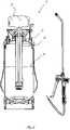
Bei der dargestellten Ausführungsform gemäß dem Stand der Technik wird der Druck im Drucksprüher mittels der Handpumpe 5 aufgebaut. Gemäß der Erfindung kann die in
Durch das Ausbringen des Sprühmittels wird der durch die Handpumpe bzw. die elektrische Pumpe im Behälter aufgebaute Druck abgebaut. Nach einem bestimmten Zeitraum muss daher durch Nachpumpen mit der Handpumpe bzw. der elektrischen Pumpe gemäß der Erfindung der Druck im Druckbehälter erneut erhöht werden, um ein Ausbringen der im Druckbehälter befindlichen Sprühmittelflüssigkeit wieder zu ermöglichen. Je größer das Gaspolster im Vergleich zum Volumen der Sprühlösung bzw. Sprühmittelflüssigkeit ist, umso länger kann der Zeitraum ab dem durch Nachpumpen der Druck wieder erhöht werden muss, gewählt werden. Erfindungsgemäß ist vorgesehen, das durch eine ständige Drucküberwachung des Druckes im Behälter und einer Regelung, die je nach Behälterdruck, der mittels des Drucksensors bestimmt wird, die elektrische Pumpe an- und ausschaltet ein konstanter Druck im Behälter bevorzugt im Bereich 1 bis 3 bar eingestellt werden kann, was mit einer Handpumpe nicht möglich ist. Bei der Handpumpe sinkt ein eingestellter Druck kontinuierlich ab.By applying the spray, the pressure built up in the container by the hand pump or the electric pump is released. After a certain period of time, the pressure in the pressure vessel must therefore be increased again by re-pumping with the hand pump or the electric pump according to the invention in order to enable the spray medium liquid in the pressure vessel to be discharged again. The larger the gas cushion is compared to the volume of the spray solution or spray liquid, the longer the period after which the pressure has to be increased again by pumping can be selected. According to the invention, a constant pressure in the container can be set, preferably in the range of 1 to 3 bar, by constantly monitoring the pressure in the container and by controlling the electric pump on and off depending on the container pressure, which is determined by the pressure sensor can do what is not possible with a hand pump. With the hand pump, a set pressure drops continuously.
Bei Herbiziden ist eine größere Tröpfchengröße anzustreben, damit ein Abdriften der Tröpfchen verhindert wird. Daher liegt der bevorzugte Druck beim Ausbringen von Herbiziden im Bereich von 1,0 bis 2,0 bar, bevorzugt bei ungefähr 1,5 bar.In the case of herbicides, a larger droplet size should be aimed for, so that the droplets are prevented from drifting. Therefore, the preferred pressure when applying herbicides is in the range of 1.0 to 2.0 bar, preferably about 1.5 bar.
Für die Schaumerzeugung ist ein höherer Druck von über 2 bar bis zu 3 bar und ein entsprechender Volumenstrom erforderlich. Eine befriedigende Schaumqualität wird im Bereich 2 bis 2,5 bar, mindestens jedoch 2 bar erreicht.A higher pressure of more than 2 bar up to 3 bar and a corresponding volume flow is required for foam generation. A satisfactory foam quality is achieved in the range from 2 to 2.5 bar, but at least 2 bar.
Das aus der
Gegenüber Einsätzen mit Druckpumpen für Sprühgeräte gemäß dem Stand der Technik wie in der
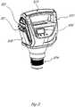
In
Zum Schutz des Motors gegen Blockieren kann vorgesehen sein, dass beim Motor ein Umkehrmodus implementiert ist. Dies hat zur Folge, dass bei ungünstiger Kolbenstellung ein Blockieren des Motors zu verhindert wird, in dem dieser im Umkehrmodus betrieben wird, d.h. der Motor kurz rückwärts läuft und dann neu startet. Die Aktivierung des Umkehrmodus des Motors erfolgt, wenn der Motorstrom einen bestimmten Wert überschreitet.To protect the motor against blocking, it can be provided that a reverse mode is implemented in the motor. As a result, if the piston is in an unfavorable position, the engine is prevented from blocking by operating it in reverse mode, i.e. the engine runs backwards for a short time and then restarts. The motor is activated into reverse mode when the motor current exceeds a certain value.
Die seitlich am Gehäuse angeordnete Speichereinrichtung 500, insbesondere der Akkumulator, bevorzugt der Li-lonen-Akkumulator ist gut in
Die eingesetzten Speichereinrichtungen, insbesondere Akkumulatoren haben eine Spannung von nominell 18V. Es können Akkumulatoren unterschiedlicher Kapazitäten zwischen 1,5 und 8 Ah verwendet werden. Bei einer Kapazität von 2,5 Ah beträgt die theoretische Nutzungskapazität für eine Akkuladung ca 60-80 Liter Flüssigkeit, die versprüht werden kann. Der Vorteil dieser Akkumulatoren ist zudem, dass diese auch für andere, kompatible Elektrogeräte verwendet werden können.The storage devices used, in particular accumulators, have a nominal voltage of 18V. Accumulators with different capacities between 1.5 and 8 Ah can be used. With a capacity of 2.5 Ah, the theoretical usage capacity for one battery charge is about 60-80 liters of liquid that can be sprayed. The advantage of these accumulators is that they can also be used for other compatible electronic devices.
Besonders bevorzugt ist es, wenn der Akkumulator mit einer zusätzlichen Schutzhülle versehen ist, um die elektrische Verbindung des Akkumulators zum Gehäuse vor eintretender Feuchtigkeit zu schützen.It is particularly preferred if the accumulator is provided with an additional protective cover in order to protect the electrical connection of the accumulator to the housing against the ingress of moisture.
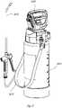
In
Der Behälter 1100 des Drucksprühgerätes ist mit einem Tragegurt 1102 versehen. Des Weiteren gut zu erkennen ist die am Behälter des Drucksprühgerätes angebrachte Drucklanze 1104 mit der die im Behälter befindliche Flüssigkeit ausgebracht werden kann. Des Weiteren umfasst der Einsatz mit der Pumpe noch einen Tragegriff 1010. Ist kein Tragegurt 1002 vorhanden, so kann das Drucksprühgerät alleine mit dem Tragegriff 1010 getragen werden. Der Tragegriff ist so ausgelegt, dass der Tragegriff in der Lage ist auch das Gewicht des befüllten Behältern aufzunehmen.The
Mit der Erfindung wird erstmals ein Drucksprühgerät mit einer elektrischen Pumpe angegeben, bei der die elektrische Versorgungseinrichtung auf einfache Art und Weise getauscht werden kann, ohne dass beispielsweise Druck aus dem Behälter abgelassen werden muss. Des Weiteren zeichnet sich der erfindungsgemäße Einsatz des Drucksprühgerätes dadurch aus, dass ein Behälterdruck eingestellt und mit Hilfe der Regelung auch bei Ausbringen von Flüssigkeit aus dem Behälter des Drucksprühgerätes gehalten werden kann.With the invention, a pressure sprayer with an electric pump is specified for the first time, in which the electrical supply device can be exchanged in a simple manner without, for example, pressure having to be released from the container. Furthermore, the use of the pressure sprayer according to the invention is characterized in that a container pressure can be set and maintained with the aid of the control even when liquid is being discharged from the container of the pressure sprayer.
ZITATE ENTHALTEN IN DER BESCHREIBUNGQUOTES INCLUDED IN DESCRIPTION
Diese Liste der vom Anmelder aufgeführten Dokumente wurde automatisiert erzeugt und ist ausschließlich zur besseren Information des Lesers aufgenommen. Die Liste ist nicht Bestandteil der deutschen Patent- bzw. Gebrauchsmusteranmeldung. Das DPMA übernimmt keinerlei Haftung für etwaige Fehler oder Auslassungen.This list of the documents cited by the applicant was generated automatically and is included solely for the better information of the reader. The list is not part of the German patent or utility model application. The DPMA assumes no liability for any errors or omissions.
Zitierte PatentliteraturPatent Literature Cited
- DE 9415691 [0003]DE 9415691 [0003]
- DE 8420572 U [0004]DE 8420572 U [0004]
- US 7207500 B2 [0006, 0007]US 7207500 B2 [0006, 0007]
- WO 2012/000578 A1 [0007, 0011, 0017, 0036, 0037]WO 2012/000578 A1 [0007, 0011, 0017, 0036, 0037]
- EP 1949972 A1 [0008]EP 1949972 A1 [0008]
- EP 2588247 B1 [0008]EP 2588247 B1 [0008]
- DE 102010017988 [0010]DE 102010017988 [0010]
- US 10137465 B2 [0011]US 10137465 B2 [0011]
Claims (11)
Translated fromGermanPriority Applications (2)
| Application Number | Priority Date | Filing Date | Title |
|---|---|---|---|
| DE102020125632.9ADE102020125632A1 (en) | 2020-10-01 | 2020-10-01 | pressure sprayer |
| EP21198194.9AEP3978141B1 (en) | 2020-10-01 | 2021-09-22 | Pressure spray device |
Applications Claiming Priority (1)
| Application Number | Priority Date | Filing Date | Title |
|---|---|---|---|
| DE102020125632.9ADE102020125632A1 (en) | 2020-10-01 | 2020-10-01 | pressure sprayer |
Publications (1)
| Publication Number | Publication Date |
|---|---|
| DE102020125632A1true DE102020125632A1 (en) | 2022-04-07 |
Family
ID=77897547
Family Applications (1)
| Application Number | Title | Priority Date | Filing Date |
|---|---|---|---|
| DE102020125632.9APendingDE102020125632A1 (en) | 2020-10-01 | 2020-10-01 | pressure sprayer |
Country Status (2)
| Country | Link |
|---|---|
| EP (1) | EP3978141B1 (en) |
| DE (1) | DE102020125632A1 (en) |
Families Citing this family (2)
| Publication number | Priority date | Publication date | Assignee | Title |
|---|---|---|---|---|
| ES1272859Y (en)* | 2021-04-29 | 2021-10-18 | Coop Goizper S | PRESSURIZED SPRAYER |
| IT202200026259A1 (en)* | 2022-12-21 | 2023-03-21 | Vitaliano Donato | POST-EXPLOSURE WALK KIT WITH ANIMAL DEJECTION PRESSURE WASHER |
Citations (12)
| Publication number | Priority date | Publication date | Assignee | Title |
|---|---|---|---|---|
| DE8420572U1 (en) | 1984-07-10 | 1984-10-11 | Kühbauch, Adam, 7410 Reutlingen | PORTABLE PRESSURE SPRAYER |
| DE9415691U1 (en) | 1994-09-28 | 1994-11-17 | Gloria-Werke H. Schulte-Frankenfeld Gmbh & Co, 59329 Wadersloh | Pressure sprayer, such as hand-held fire extinguishers, crop protection sprayers or the like. |
| US5409167A (en) | 1993-08-24 | 1995-04-25 | Borod; Murray | Hygienic spray apparatus |
| US5931207A (en) | 1997-03-05 | 1999-08-03 | Gianino; Rosario N. | Portable home and garden sprayer, power unit |
| US6109548A (en) | 1999-07-01 | 2000-08-29 | George; Vernon | Sprayer system |
| US20050045745A1 (en) | 2003-08-13 | 2005-03-03 | Unilever Home & Personal Care Usa, Division Of Conopco, Inc. | Domestic spray device |
| US7207500B2 (en) | 2004-10-13 | 2007-04-24 | H.D. Hudson Manufacturing Co. | Battery-powered pump for liquid sprayer |
| EP1949972A1 (en) | 2007-01-29 | 2008-07-30 | Goizper, S. Coop. | Power-operated sprayer, for manual use |
| DE102010017988A1 (en) | 2010-04-21 | 2011-10-27 | Al-Ko Kober Ag | Riding mower, has brake pedals connected with power transmission mechanism for driving mower in forward direction, where pedal drives of another power transmission mechanism are partially decoupled for actuating brake pedals |
| WO2012000578A1 (en) | 2010-06-30 | 2012-01-05 | Markus Kress | Insert for a pressurized container with an electric pump, and pressurized container having such an insert |
| US20160243570A1 (en) | 2015-02-13 | 2016-08-25 | Green Shoots, LLC | Electric tank dispenser having a pressurizable space and selectable pressure levels |
| US10137465B2 (en) | 2015-06-25 | 2018-11-27 | Suzhou Crosstec Co., Ltd. | Electric sprayer |
Family Cites Families (6)
| Publication number | Priority date | Publication date | Assignee | Title |
|---|---|---|---|---|
| FR2817142B1 (en) | 2000-11-24 | 2003-05-16 | Sofradim Production | PROSTHETIC FASTENER AND TRANSCUTANEOUS INSERTION DEVICE |
| DE102009048572A1 (en) | 2009-10-07 | 2011-04-28 | Markus Kress | Pressure sprayer |
| JP2013169486A (en)* | 2012-02-17 | 2013-09-02 | Hitachi Koki Co Ltd | High pressure washing device |
| US9538872B2 (en)* | 2014-03-07 | 2017-01-10 | Prince Castle LLC | Pressurized viscous condiment dispenser |
| DE102014012433A1 (en)* | 2014-08-26 | 2016-03-03 | Markus Kress | Device for admixing a liquid substrate and device for spraying a liquid |
| US10532370B2 (en)* | 2015-10-20 | 2020-01-14 | Phillip B. Schrum | Portable pressurized sprayer |
- 2020
- 2020-10-01DEDE102020125632.9Apatent/DE102020125632A1/enactivePending
- 2021
- 2021-09-22EPEP21198194.9Apatent/EP3978141B1/enactiveActive
Patent Citations (13)
| Publication number | Priority date | Publication date | Assignee | Title |
|---|---|---|---|---|
| DE8420572U1 (en) | 1984-07-10 | 1984-10-11 | Kühbauch, Adam, 7410 Reutlingen | PORTABLE PRESSURE SPRAYER |
| US5409167A (en) | 1993-08-24 | 1995-04-25 | Borod; Murray | Hygienic spray apparatus |
| DE9415691U1 (en) | 1994-09-28 | 1994-11-17 | Gloria-Werke H. Schulte-Frankenfeld Gmbh & Co, 59329 Wadersloh | Pressure sprayer, such as hand-held fire extinguishers, crop protection sprayers or the like. |
| US5931207A (en) | 1997-03-05 | 1999-08-03 | Gianino; Rosario N. | Portable home and garden sprayer, power unit |
| US6109548A (en) | 1999-07-01 | 2000-08-29 | George; Vernon | Sprayer system |
| US20050045745A1 (en) | 2003-08-13 | 2005-03-03 | Unilever Home & Personal Care Usa, Division Of Conopco, Inc. | Domestic spray device |
| US7207500B2 (en) | 2004-10-13 | 2007-04-24 | H.D. Hudson Manufacturing Co. | Battery-powered pump for liquid sprayer |
| EP1949972A1 (en) | 2007-01-29 | 2008-07-30 | Goizper, S. Coop. | Power-operated sprayer, for manual use |
| DE102010017988A1 (en) | 2010-04-21 | 2011-10-27 | Al-Ko Kober Ag | Riding mower, has brake pedals connected with power transmission mechanism for driving mower in forward direction, where pedal drives of another power transmission mechanism are partially decoupled for actuating brake pedals |
| WO2012000578A1 (en) | 2010-06-30 | 2012-01-05 | Markus Kress | Insert for a pressurized container with an electric pump, and pressurized container having such an insert |
| EP2588247B1 (en) | 2010-06-30 | 2014-08-20 | Markus Kress | Insert for a pressurized container with an electric pump, and pressurized container having such an insert |
| US20160243570A1 (en) | 2015-02-13 | 2016-08-25 | Green Shoots, LLC | Electric tank dispenser having a pressurizable space and selectable pressure levels |
| US10137465B2 (en) | 2015-06-25 | 2018-11-27 | Suzhou Crosstec Co., Ltd. | Electric sprayer |
Also Published As
| Publication number | Publication date |
|---|---|
| EP3978141B1 (en) | 2025-05-14 |
| EP3978141A1 (en) | 2022-04-06 |
Similar Documents
| Publication | Publication Date | Title |
|---|---|---|
| EP3978141B1 (en) | Pressure spray device | |
| DE60107957T2 (en) | FLÜSSIGKEITSSPRÜHGERÄTE | |
| DE69619819T2 (en) | KNAPSACK SPRAYER | |
| EP3408033B1 (en) | Dispensing device for spaying of a sprayable fluid | |
| CH713274A2 (en) | Device for firing a projectile. | |
| WO2003043112A1 (en) | Devices for supplying fuel to fuel cells | |
| DE102007022980A1 (en) | Independent equipment for the application of paints | |
| DE4231826A1 (en) | Device for atomizing liquids | |
| WO2000059566A1 (en) | Breathing apparatus | |
| DE4304091C2 (en) | Massager | |
| DE69907668T2 (en) | PRESSURE CONTROLLED WATER SUPPLY SYSTEM | |
| DE102019105738A1 (en) | Device with disinfectant dispensing function, in particular for door handles or ironing or bar handles | |
| DE202006002469U1 (en) | Device for pneumatically spraying viscose fluids with container and spraying system | |
| EP1706211B1 (en) | Device and spray head for atomising a cosmetic liquid | |
| DE602004003027T2 (en) | liquid sprayer | |
| DE2427211C3 (en) | Spray device | |
| DE102010017998B4 (en) | Pressure sprayer | |
| DE102015002241A1 (en) | Filling device and method for filling a gas storage | |
| DE202015001244U1 (en) | Mobile travel shower | |
| EP2644023A1 (en) | Manual plant irrigation device | |
| DE202008006952U1 (en) | grease Gun | |
| EP2588247B1 (en) | Insert for a pressurized container with an electric pump, and pressurized container having such an insert | |
| DE202005019242U1 (en) | Device for dispersing cleaning and care agents, has large medium pressure container provided with defined external valves possibly swiveled inside and is replaced by tubular mixing and air chamber | |
| DE19741424A1 (en) | Breathing device for divers | |
| DE3910395A1 (en) | Painting outfit with roller or brush, of increased productivity, which ensures a continuous supply of paint to the working region by means of the pressure generated in the paint can |
Legal Events
| Date | Code | Title | Description |
|---|---|---|---|
| R012 | Request for examination validly filed | ||
| R016 | Response to examination communication |