DE102020118265A1 - Medical instrument and electrosurgical system - Google Patents
Medical instrument and electrosurgical systemDownload PDFInfo
- Publication number
- DE102020118265A1 DE102020118265A1DE102020118265.1ADE102020118265ADE102020118265A1DE 102020118265 A1DE102020118265 A1DE 102020118265A1DE 102020118265 ADE102020118265 ADE 102020118265ADE 102020118265 A1DE102020118265 A1DE 102020118265A1
- Authority
- DE
- Germany
- Prior art keywords
- neutral electrode
- electrode surface
- instrument
- supply line
- neutral
- Prior art date
- Legal status (The legal status is an assumption and is not a legal conclusion. Google has not performed a legal analysis and makes no representation as to the accuracy of the status listed.)
- Pending
Links
- 230000007935neutral effectEffects0.000claimsabstractdescription113
- 238000005520cutting processMethods0.000claimsabstractdescription7
- 238000009413insulationMethods0.000claimsdescription6
- 229910052751metalInorganic materials0.000claimsdescription4
- 239000002184metalSubstances0.000claimsdescription4
- 210000001519tissueAnatomy0.000description5
- 230000000694effectsEffects0.000description3
- 238000004519manufacturing processMethods0.000description3
- 238000002324minimally invasive surgeryMethods0.000description3
- 229910000831SteelInorganic materials0.000description2
- 239000011324beadSubstances0.000description2
- 239000012212insulatorSubstances0.000description2
- 238000000034methodMethods0.000description2
- 239000010959steelSubstances0.000description2
- 238000001356surgical procedureMethods0.000description2
- WFKWXMTUELFFGS-UHFFFAOYSA-NtungstenChemical compound[W]WFKWXMTUELFFGS-UHFFFAOYSA-N0.000description2
- 229910052721tungstenInorganic materials0.000description2
- 239000010937tungstenSubstances0.000description2
- BUHVIAUBTBOHAG-FOYDDCNASA-N(2r,3r,4s,5r)-2-[6-[[2-(3,5-dimethoxyphenyl)-2-(2-methylphenyl)ethyl]amino]purin-9-yl]-5-(hydroxymethyl)oxolane-3,4-diolChemical compoundCOC1=CC(OC)=CC(C(CNC=2C=3N=CN(C=3N=CN=2)[C@H]2[C@@H]([C@H](O)[C@@H](CO)O2)O)C=2C(=CC=CC=2)C)=C1BUHVIAUBTBOHAG-FOYDDCNASA-N0.000description1
- 238000012084abdominal surgeryMethods0.000description1
- 230000015572biosynthetic processEffects0.000description1
- 238000004140cleaningMethods0.000description1
- 239000004020conductorSubstances0.000description1
- 238000002955isolationMethods0.000description1
- 210000000056organAnatomy0.000description1
- 210000002307prostateAnatomy0.000description1
Images

Classifications
- A—HUMAN NECESSITIES
- A61—MEDICAL OR VETERINARY SCIENCE; HYGIENE
- A61B—DIAGNOSIS; SURGERY; IDENTIFICATION
- A61B18/00—Surgical instruments, devices or methods for transferring non-mechanical forms of energy to or from the body
- A61B18/04—Surgical instruments, devices or methods for transferring non-mechanical forms of energy to or from the body by heating
- A61B18/12—Surgical instruments, devices or methods for transferring non-mechanical forms of energy to or from the body by heating by passing a current through the tissue to be heated, e.g. high-frequency current
- A61B18/14—Probes or electrodes therefor
- A61B18/149—Probes or electrodes therefor bow shaped or with rotatable body at cantilever end, e.g. for resectoscopes, or coagulating rollers
- A—HUMAN NECESSITIES
- A61—MEDICAL OR VETERINARY SCIENCE; HYGIENE
- A61B—DIAGNOSIS; SURGERY; IDENTIFICATION
- A61B18/00—Surgical instruments, devices or methods for transferring non-mechanical forms of energy to or from the body
- A61B18/04—Surgical instruments, devices or methods for transferring non-mechanical forms of energy to or from the body by heating
- A61B18/12—Surgical instruments, devices or methods for transferring non-mechanical forms of energy to or from the body by heating by passing a current through the tissue to be heated, e.g. high-frequency current
- A61B18/14—Probes or electrodes therefor
- A61B18/16—Indifferent or passive electrodes for grounding
- A—HUMAN NECESSITIES
- A61—MEDICAL OR VETERINARY SCIENCE; HYGIENE
- A61B—DIAGNOSIS; SURGERY; IDENTIFICATION
- A61B18/00—Surgical instruments, devices or methods for transferring non-mechanical forms of energy to or from the body
- A61B18/04—Surgical instruments, devices or methods for transferring non-mechanical forms of energy to or from the body by heating
- A61B18/12—Surgical instruments, devices or methods for transferring non-mechanical forms of energy to or from the body by heating by passing a current through the tissue to be heated, e.g. high-frequency current
- A61B18/1206—Generators therefor
- A—HUMAN NECESSITIES
- A61—MEDICAL OR VETERINARY SCIENCE; HYGIENE
- A61B—DIAGNOSIS; SURGERY; IDENTIFICATION
- A61B18/00—Surgical instruments, devices or methods for transferring non-mechanical forms of energy to or from the body
- A61B2018/00053—Mechanical features of the instrument of device
- A61B2018/00184—Moving parts
- A61B2018/00196—Moving parts reciprocating lengthwise
- A—HUMAN NECESSITIES
- A61—MEDICAL OR VETERINARY SCIENCE; HYGIENE
- A61B—DIAGNOSIS; SURGERY; IDENTIFICATION
- A61B18/00—Surgical instruments, devices or methods for transferring non-mechanical forms of energy to or from the body
- A61B2018/00315—Surgical instruments, devices or methods for transferring non-mechanical forms of energy to or from the body for treatment of particular body parts
- A61B2018/00434—Neural system
- A—HUMAN NECESSITIES
- A61—MEDICAL OR VETERINARY SCIENCE; HYGIENE
- A61B—DIAGNOSIS; SURGERY; IDENTIFICATION
- A61B18/00—Surgical instruments, devices or methods for transferring non-mechanical forms of energy to or from the body
- A61B2018/00315—Surgical instruments, devices or methods for transferring non-mechanical forms of energy to or from the body for treatment of particular body parts
- A61B2018/00505—Urinary tract
- A61B2018/00517—Urinary bladder or urethra
- A—HUMAN NECESSITIES
- A61—MEDICAL OR VETERINARY SCIENCE; HYGIENE
- A61B—DIAGNOSIS; SURGERY; IDENTIFICATION
- A61B18/00—Surgical instruments, devices or methods for transferring non-mechanical forms of energy to or from the body
- A61B2018/00315—Surgical instruments, devices or methods for transferring non-mechanical forms of energy to or from the body for treatment of particular body parts
- A61B2018/00547—Prostate
- A—HUMAN NECESSITIES
- A61—MEDICAL OR VETERINARY SCIENCE; HYGIENE
- A61B—DIAGNOSIS; SURGERY; IDENTIFICATION
- A61B18/00—Surgical instruments, devices or methods for transferring non-mechanical forms of energy to or from the body
- A61B2018/00315—Surgical instruments, devices or methods for transferring non-mechanical forms of energy to or from the body for treatment of particular body parts
- A61B2018/00559—Female reproductive organs
- A—HUMAN NECESSITIES
- A61—MEDICAL OR VETERINARY SCIENCE; HYGIENE
- A61B—DIAGNOSIS; SURGERY; IDENTIFICATION
- A61B18/00—Surgical instruments, devices or methods for transferring non-mechanical forms of energy to or from the body
- A61B2018/00571—Surgical instruments, devices or methods for transferring non-mechanical forms of energy to or from the body for achieving a particular surgical effect
- A61B2018/00601—Cutting
- A—HUMAN NECESSITIES
- A61—MEDICAL OR VETERINARY SCIENCE; HYGIENE
- A61B—DIAGNOSIS; SURGERY; IDENTIFICATION
- A61B18/00—Surgical instruments, devices or methods for transferring non-mechanical forms of energy to or from the body
- A61B18/04—Surgical instruments, devices or methods for transferring non-mechanical forms of energy to or from the body by heating
- A61B18/12—Surgical instruments, devices or methods for transferring non-mechanical forms of energy to or from the body by heating by passing a current through the tissue to be heated, e.g. high-frequency current
- A61B18/1206—Generators therefor
- A61B2018/1246—Generators therefor characterised by the output polarity
- A61B2018/126—Generators therefor characterised by the output polarity bipolar
- A—HUMAN NECESSITIES
- A61—MEDICAL OR VETERINARY SCIENCE; HYGIENE
- A61B—DIAGNOSIS; SURGERY; IDENTIFICATION
- A61B18/00—Surgical instruments, devices or methods for transferring non-mechanical forms of energy to or from the body
- A61B18/04—Surgical instruments, devices or methods for transferring non-mechanical forms of energy to or from the body by heating
- A61B18/12—Surgical instruments, devices or methods for transferring non-mechanical forms of energy to or from the body by heating by passing a current through the tissue to be heated, e.g. high-frequency current
- A61B18/14—Probes or electrodes therefor
- A61B2018/1475—Electrodes retractable in or deployable from a housing
- A—HUMAN NECESSITIES
- A61—MEDICAL OR VETERINARY SCIENCE; HYGIENE
- A61B—DIAGNOSIS; SURGERY; IDENTIFICATION
- A61B18/00—Surgical instruments, devices or methods for transferring non-mechanical forms of energy to or from the body
- A61B18/04—Surgical instruments, devices or methods for transferring non-mechanical forms of energy to or from the body by heating
- A61B18/12—Surgical instruments, devices or methods for transferring non-mechanical forms of energy to or from the body by heating by passing a current through the tissue to be heated, e.g. high-frequency current
- A61B18/14—Probes or electrodes therefor
- A61B18/16—Indifferent or passive electrodes for grounding
- A61B2018/162—Indifferent or passive electrodes for grounding located on the probe body
- A—HUMAN NECESSITIES
- A61—MEDICAL OR VETERINARY SCIENCE; HYGIENE
- A61B—DIAGNOSIS; SURGERY; IDENTIFICATION
- A61B18/00—Surgical instruments, devices or methods for transferring non-mechanical forms of energy to or from the body
- A61B18/04—Surgical instruments, devices or methods for transferring non-mechanical forms of energy to or from the body by heating
- A61B18/12—Surgical instruments, devices or methods for transferring non-mechanical forms of energy to or from the body by heating by passing a current through the tissue to be heated, e.g. high-frequency current
- A61B18/14—Probes or electrodes therefor
- A61B18/16—Indifferent or passive electrodes for grounding
- A61B2018/165—Multiple indifferent electrodes
Landscapes
- Health & Medical Sciences (AREA)
- Surgery (AREA)
- Engineering & Computer Science (AREA)
- Life Sciences & Earth Sciences (AREA)
- Biomedical Technology (AREA)
- Otolaryngology (AREA)
- Nuclear Medicine, Radiotherapy & Molecular Imaging (AREA)
- Plasma & Fusion (AREA)
- Physics & Mathematics (AREA)
- Heart & Thoracic Surgery (AREA)
- Medical Informatics (AREA)
- Molecular Biology (AREA)
- Animal Behavior & Ethology (AREA)
- General Health & Medical Sciences (AREA)
- Public Health (AREA)
- Veterinary Medicine (AREA)
- Surgical Instruments (AREA)
Abstract
Translated fromGermanDescription
Translated fromGermanBipolares medizinisches Instrument zum Schneiden von Gewebe unter der Wirkung von Hochfrequenzstrom, wobei sich das Instrument entlang einer Längsrichtung von einem proximalen Ende zu einem distalen Ende erstreckt und wobei am distalen Ende eine Aktivelektrode und eine der Aktivelektrode benachbarten Neutralelektrode angeordnet sind.Bipolar medical instrument for cutting tissue under the effect of high-frequency current, wherein the instrument extends along a longitudinal direction from a proximal end to a distal end and wherein an active electrode and a neutral electrode adjacent to the active electrode are arranged at the distal end.
Die Erfindung betrifft ferner ein elektrochirurgisches System, mit einem Hochfrequenzgenerator und einem Instrument der eingangs genannten Art.The invention also relates to an electrosurgical system with a high-frequency generator and an instrument of the type mentioned at the outset.
Ein Instrument und ein System der eingangs genannten Art sind aus
Ein Instrument bzw. ein System der eingangs genannten Art wird in der offenen, vorzugsweise aber in der minimal-invasiven Chirurgie zum Schneiden von Gewebe im menschlichen oder tierischen Körper verwendet.An instrument or a system of the type mentioned is used in open surgery, but preferably in minimally invasive surgery, for cutting tissue in the human or animal body.
Das eingangs genannte Instrument kann im Sinne der vorliegenden Erfindung bei Verwendung in der minimalinvasiven Chirurgie zusammen mit einem Endoskop zu einem sogenannten Resektoskop kombiniert werden oder selbst ein solches Resektoskop darstellen.In terms of the present invention, the instrument mentioned at the beginning can be combined with an endoscope to form a so-called resectoscope when used in minimally invasive surgery, or it can itself represent such a resectoscope.
Die Elektro- oder Hochfrequenzchirurgie wird therapeutisch in verschiedenen medizinischen Fachdisziplinen wie bspw. der Urologie, Gynäkologie, Neurochirurgie, Abdominalchirurgie usw. eingesetzt. Speziell in der Urologie wird mittels eines eingangs genannten Instruments im Rahmen der minimal-invasiven Chirurgie endoskopisch Prostatagewebe abgetragen.Electrosurgery or high-frequency surgery is used therapeutically in various medical disciplines such as urology, gynaecology, neurosurgery, abdominal surgery, etc. Especially in urology, prostate tissue is endoscopically removed using an instrument mentioned at the outset as part of minimally invasive surgery.
Bei elektrochirurgischen Verfahren der Resektoskopie unterscheidet man zwischen der monopolaren und der bipolaren Applikation des Hochfrequenzstromes.In electrosurgical resectoscopy procedures, a distinction is made between monopolar and bipolar application of the high-frequency current.
Bei der monopolaren Applikation wird nur die Aktivelektrode, manchmal auch als Schneidelektrode oder Behandlungselektrode bezeichnet, in das Behandlungsgebiet eingeführt, während die Neutralelektrode außen am Patienten angeordnet wird. Folglich führt der Stromfluss zwischen der Aktivelektrode und der Neutralelektrode durch den Körper des Patienten hindurch, wobei der Nachteil besteht, dass der Strompfad durch den Patienten nicht sicher kontrolliert werden kann mit der Folge möglicher Verletzungen von Organen. Darüber hinaus kann die am Patientenkörper angebrachte Neutralelektrode zu Verbrennungen der Haut des Patienten führen.With the monopolar application, only the active electrode, sometimes referred to as the cutting electrode or treatment electrode, is inserted into the treatment area, while the neutral electrode is placed on the outside of the patient. As a result, the current flow between the active electrode and the neutral electrode passes through the patient's body, with the disadvantage that the current path through the patient cannot be safely controlled, with the result that organs may be injured. In addition, the neutral electrode attached to the patient's body can burn the patient's skin.
Bei der bipolaren Technik, von der die vorliegende Erfindung ausgeht, werden sowohl Aktivelektrode als auch Neutralelektrode in das Behandlungsgebiet eingeführt. Der Stromfluss kann dadurch in kontrollierbarer Weise auf den Bereich zwischen der Aktivelektrode und der Neutralelektrode begrenzt werden, dass er räumlich nur zwischen der Aktivelektrode und der Neutralelektrode fließt. Entsprechend sind medizinische Instrumente der eingangs genannten Art geschaffen worden, bei denen die Aktivelektrode und die Neutralelektrode an einem Elektrodenträger angeordnet sind, so dass die Aktivelektrode und die Neutralelektrode einander benachbart in das Behandlungsgebiet eingebracht werden können.In the bipolar technique on which the present invention is based, both the active electrode and the neutral electrode are introduced into the treatment area. The current flow can be limited in a controllable manner to the area between the active electrode and the neutral electrode in that it only flows spatially between the active electrode and the neutral electrode. Correspondingly, medical instruments of the type mentioned at the outset have been created in which the active electrode and the neutral electrode are arranged on an electrode carrier, so that the active electrode and the neutral electrode can be introduced into the treatment area adjacent to one another.
Bei bipolaren medizinischen Instrumenten der eingangs genannten Art ist die Aktivelektrode üblicherweise mit einer kleinen wirksamen Oberfläche ausgebildet, so dass sich an der Aktivelektrode eine hohe Stromdichte einstellt, während die Neutralelektrode üblicherweise relativ großflächig ausgebildet ist, so dass sich an der Neutralelektrode nur mittlere oder geringe Stromdichten einstellen. Mit der Aktivelektrode wird entsprechend geschnitten, während die Neutralelektrode möglichst keine Wirkung auf das Gewebe ausüben soll, sondern lediglich der Begrenzung des Strompfades auf den Bereich zwischen der Aktivelektrode und der Neutralelektrode dienen soll.In the case of bipolar medical instruments of the type mentioned at the outset, the active electrode is usually designed with a small effective surface, so that a high current density is established at the active electrode, while the neutral electrode is usually designed with a relatively large area, so that only medium or low current densities occur at the neutral electrode to adjust. The active electrode is used to cut accordingly, while the neutral electrode should have as little effect on the tissue as possible, but should only serve to limit the current path to the area between the active electrode and the neutral electrode.
Bei dem aus der oben genannten
Aus
Der Erfindung liegt die Aufgabe zu Grunde, ein verbessertes Instrument sowie ein verbessertes System der eingangs genannten Art bereitzustellen.The invention is based on the object of providing an improved instrument and an improved system of the type mentioned at the outset.
Die Aufgabe wird gelöst durch ein bipolares medizinisches Instrument zum Schneiden von Gewebe unter der Wirkung von Hochfrequenzstrom, wobei sich das Instrument entlang einer Längsrichtung von einem proximalen Ende zu einem distalen Ende erstreckt und wobei am distalen Ende eine Aktivelektrode und eine der Aktivelektrode benachbarten Neutralelektrode angeordnet sind und die Neutralelektrode eine erste elektrische Zuleitung, die vom proximalen Ende zur Aktivelektrode führt, in einem ersten Abschnitt des Instruments zumindest teilweise umschließt, wobei die Neutralelektrode eine erste gekrümmte Neutralelektrodenfläche und eine zweite gekrümmte Neutralelektrodenfläche aufweist, die erste Neutralelektrodenfläche mit einer zweiten Zuleitung verbunden ist, die vom proximalen Ende zur ersten Neutralelektrodenfläche führt, und die zweite Neutralelektrodenfläche mit einer dritten Zuleitung verbunden ist, die vom proximalen Ende zur zweiten Neutralelektrodenfläche führt, und wobei die zweite elektrische Zuleitung in proximaler Richtung vor dem ersten Abschnitt die erste elektrische Zuleitung zumindest teilweise umschließt.The object is achieved by a bipolar medical instrument for cutting tissue under the action of high-frequency current, the instrument extending along a longitudinal direction from a proximal end to a distal end and an active electrode and a neutral electrode adjacent to the active electrode being arranged at the distal end and the neutral electrode at least partially encloses a first electrical supply line, which leads from the proximal end to the active electrode, in a first section of the instrument, the neutral electrode having a first curved neutral electrode surface and a second curved neutral electrode surface, the first neutral electrode surface being connected to a second supply line, which leads from the proximal end to the first neutral electrode surface, and the second neutral electrode surface is connected to a third supply line, which leads from the proximal end to the second neutral electrode surface, and the second ele ktric lead in the proximal direction in front of the first section encloses the first electrical lead at least partially.
Einer der Vorteile, die sich mit einem solchen Instrument erzielen lassen, ist die Ausgestaltung als getrennte Gestänge, später in den Figuren als Elektrodenträgerteile bezeichnet. Die Gestänge können dabei einfach mit Klammern verbunden werden, später in den Figuren als Haltelemente bezeichnet. Jedes Gestänge enthält eine Zu- und Rückführung der Energie, die im Betrieb von einem Hochfrequenzgenerator geliefert wird. Dabei lässt sich insbesondere eine erhöhte mechanische Stabilität erzielen.One of the advantages that can be achieved with such an instrument is the design as separate linkages, referred to later in the figures as electrode support parts. The rods can be easily connected with brackets, later referred to as holding elements in the figures. Each linkage contains a supply and return of energy, which is supplied by a high-frequency generator during operation. In this way, in particular, increased mechanical stability can be achieved.
Bei einer bevorzugten Ausgestaltung sind die erste Neutralelektrodenfläche und die zweite Neutralelektrodenfläche am distalen Ende nicht elektrisch verbunden und/oder nur am proximalen Ende elektrisch verbunden.In a preferred embodiment, the first neutral electrode surface and the second neutral electrode surface are not electrically connected at the distal end and/or are electrically connected only at the proximal end.
Bei dieser Ausgestaltung wird keine elektrische Brücke zwischen den Gestängen benötigt. Die Neutralelektroden sind separat konnektiert, ohne eine direkte Verbindung miteinander.With this configuration, no electrical bridge is required between the linkages. The neutral electrodes are connected separately, without a direct connection to each other.
Bei einer weiteren bevorzugten Ausgestaltung sind die zweite Zuleitung und/oder die dritte Zuleitung röhrenförmig ausgebildet.In a further preferred configuration, the second supply line and/or the third supply line are/are of tubular design.
Dies ergibt einen stabilen Aufbau, der sich gut für eine effiziente Herstellung eignet.This results in a stable structure that lends itself well to efficient manufacture.
Bei einer weiteren bevorzugten Ausgestaltung laufen die erste Neutralelektrodenfläche oder die zweite elektrische Zuleitung in einem zweiten Abschnitt in proximaler Richtung konisch zu.In a further preferred configuration, the first neutral electrode surface or the second electrical feed line tapers in a second section in the proximal direction.
Diese Ausgestaltung ermöglicht es in den verschiedenen Abschnitten des Instruments entlang seiner Längserstreckung einen zumindest im Wesentlichen gleichbleibenden Durchmesser der Gestänge zu erzielen.This configuration makes it possible to achieve an at least essentially constant diameter of the linkage in the various sections of the instrument along its length.
Bei einer weiteren bevorzugten Ausgestaltung umschließt die erste Neutralelektrodenfläche die erste elektrische Zuleitung zu zumindest 120°, bevorzugt zumindest 180°, besonders bevorzugt zumindest 270° und insbesondere vollständig.In a further preferred configuration, the first neutral electrode surface encloses the first electrical supply line by at least 120°, preferably at least 180°, particularly preferably at least 270° and in particular completely.
Bei dieser Ausgestaltung kann der Grad der Umschließung je nach Anwendungsfall festgelegt werden. Dabei wird eine vollständige Umschließung als vorteilhaft hinsichtlich der Fertigung angesehen. Diese Ausführungen gelten entsprechend auch für die zweite Neutralelektrodenfläche.In this configuration, the degree of enclosure can be determined depending on the application. A complete enclosure is considered to be advantageous in terms of production. These statements also apply correspondingly to the second neutral electrode surface.
Bei einer weiteren bevorzugten Ausgestaltung umschließt die zweite elektrische Zuleitung die erste elektrische Zuleitung zu zumindest 120°, bevorzugt zumindest 180°, besonders bevorzugt zumindest 270° und insbesondere vollständig.In a further preferred configuration, the second electrical supply line encloses the first electrical supply line by at least 120°, preferably at least 180°, particularly preferably at least 270° and in particular completely.
Bei dieser Ausgestaltung kann der Grad der Umschließung je nach Anwendungsfall festgelegt werden. Dabei wird eine vollständige Umschließung als vorteilhaft hinsichtlich der Fertigung angesehen. Diese Ausführungen gelten entsprechend auch für die dritte Zuleitung.In this configuration, the degree of enclosure can be determined depending on the application. A complete enclosure is considered to be advantageous in terms of production. These statements also apply correspondingly to the third supply line.
Bei einer weiteren bevorzugten Ausgestaltung ist die zweite elektrische Zuleitung in einer rohrförmigen Isolierung geführt ist, die optional von einem metallischen Röhrchen umschlossen ist.In a further preferred embodiment, the second electrical supply line is routed in tubular insulation, which is optionally surrounded by a metal tube.
Diese Ausgestaltung bietet eine gute Art der Isolierung. Mit dem optionalen metallischen Röhrchen kann eine gute Reinigung des Instruments erzielt werden.This configuration provides a good form of isolation. A good cleaning of the instrument can be achieved with the optional metallic tube.
Bei einer weiteren bevorzugten Ausgestaltung entspricht ein Durchmesser der rohrförmigen Isolierung oder, wenn vorhanden, ein Durchmesser des metallischen Röhrchens zumindest in etwa dem Durchmesser der ersten Neutralelektrodenfläche.In a further preferred embodiment, a diameter of the tubular insulation or, if present, a diameter of the metal tube corresponds at least approximately to the diameter of the first neutral electrode surface.
Bei dieser Ausgestaltung kann ein konstanter Durchmesser der Gestänge bzw. der Elektrodenträgerteile erzielt werden.With this configuration, a constant diameter of the linkage or of the electrode carrier parts can be achieved.
Bei einer weiteren bevorzugten Ausgestaltung ist die erste Neutralelektrodenfläche an ihrem distalen Ende radial aufgeweitet.In a further preferred embodiment, the first neutral electrode surface is radially widened at its distal end.
Diese Ausgestaltung kann das Zündverhalten verbessern und kann insbesondere als Bördelung oder Flansch ausgeführt sein.This configuration can improve the ignition behavior and can be designed in particular as a bead or flange.
Bei einer weiteren bevorzugten Ausgestaltung ist in distaler Richtung vor der ersten Neutralelektrodenfläche ein rohrförmiges Isolierstück angeordnet, das die zweite Zuleitung umschließt, wobei das Isolierstück optional teilweise von der ersten Neutralelektrodenfläche umschlossen ist.In a further preferred configuration, a tubular insulating piece is arranged in the distal direction in front of the first neutral electrode surface, which encloses the second supply line, the insulating piece optionally being partially enclosed by the first neutral electrode surface.
Bei dieser Ausgestaltung kann das Risiko eines ungewolltes Zünden der Neutralelektrode verringert werden.With this configuration, the risk of the neutral electrode unintentionally igniting can be reduced.
Bei einer weiteren bevorzugten Ausgestaltung entfernen sich die erste Neutralelektrodenfläche und die zweite Neutralelektrodenfläche in distaler Richtung voneinander.In a further preferred configuration, the first neutral electrode surface and the second neutral electrode surface move away from one another in the distal direction.
Diese Ausgestaltung ermöglicht auch bei kompakter Bauweise eine ausreichend große Aktivelektrode. Ein Winkel zwischen den beiden Neutralelektrodenflächen, genauer, zwischen den beiden Längserstreckungen der Neutralelektrodenflächen beträgt bevorzugt 0,1° - 20°, besonders bevorzugt 2° - 10° und insbesondere 5° - 7°.This configuration enables a sufficiently large active electrode even with a compact design. An angle between the two neutral electrode surfaces, more precisely, between the two longitudinal extents of the neutral electrode surfaces, is preferably 0.1°-20°, particularly preferably 2°-10° and in particular 5°-7°.
Bei einer weiteren bevorzugten Ausgestaltung tritt die Aktivelektrode aus der Neutralelektrode aus, insbesondere durch ein Isolierstück hindurchgeführt, und erstreckt sich quer zur Längserstreckung von der ersten Neutralelektrodenfläche zur zweiten Neutralelektrodenfläche.In a further preferred configuration, the active electrode emerges from the neutral electrode, in particular passed through an insulating piece, and extends transversely to the longitudinal extension from the first neutral electrode surface to the second neutral electrode surface.
Diese Ausgestaltung bietet eine Ausgestaltung der Aktivelektrode, die es dem Arzt ermöglicht, in einem ihm bekannten Weise zu arbeiten.This configuration offers a configuration of the active electrode which enables the physician to work in a manner known to him.
Bei einer weiteren bevorzugten Ausgestaltung ist am proximalen Ende ein erster Kontaktierbereich der ersten Zuleitung und ein zweiter Kontaktierbereich der zweiten Zuleitung ausgebildet, die entlang der Längsrichtung versetzt zueinander angeordnet sind, und weisen die Kontaktierbereiche insbesondere jeweils eine zylinderförmige Oberfläche auf.In a further preferred embodiment, a first contacting area of the first lead and a second contacting area of the second lead are formed at the proximal end, which are offset from one another along the longitudinal direction, and the contacting areas each have a cylindrical surface.
Diese Ausgestaltung ermöglich eine Mehrfachkontaktierung, insbesondere mit vier Kontaktstellen. Dabei kann insbesondere eine großflächige Kontaktierung erzielt werden, wenn die Längserstreckung der Kontaktierbereiche größer ist als deren jeweiliger Radius, bevorzugt mehr als zweimal so groß und besonders bevorzug mehr als dreimal so groß. Es lässt sich ein reduzierter Übergangswiderstand erzielen. Außerdem kann ein Wärmeverlust an den Kontaktstellen verringert werden. Wie später noch gezeigt wird, ist insbesondere die erste Zuleitung innerhalb des zweiten Kontaktierbereichs durch den Kontaktierbereich geführt. Dieser Aufbau gilt für beide Gestänge des Instruments in entsprechender Weise.This refinement enables multiple contacting, in particular with four contact points. Large-area contacting can be achieved in particular if the longitudinal extent of the contacting areas is greater than their respective radius, preferably more than twice as large and particularly preferably more than three times as large. A reduced contact resistance can be achieved. In addition, heat loss at the contact points can be reduced. As will be shown later, in particular the first lead is routed through the contacting area within the second contacting area. This structure applies to both linkages of the instrument in a corresponding manner.
Bei einer weiteren bevorzugten Ausgestaltung ist an der Aktivelektrode eine Kante ausgebildet.In a further preferred configuration, an edge is formed on the active electrode.
Diese Ausgestaltung kann das Zündverhalten verbessern. Es sei darauf hingewiesen, dass es sich hierbei um eine eigenständige Weiterbildung einer Aktivelektrode aus dem Stand der Technik handelt, die auch ohne die beanspruchten Zuleitungen und Neutralelektrodenflächen eine erfinderische Tätigkeit begründet.This configuration can improve ignition performance. It should be pointed out that this is an independent development of an active electrode from the prior art, which constitutes an inventive step even without the claimed supply lines and neutral electrode surfaces.
Bei einer weiteren bevorzugten Ausgestaltung beträgt das Flächenverhältnis zwischen der Neutralelektrode und der Aktivelektrode 1 bis 10, bevorzugt 2 bis 8, besonders bevorzugt 3 bis 6 und insbesondere zumindest ungefähr 4.In a further preferred embodiment, the area ratio between the neutral electrode and the active electrode is 1 to 10, preferably 2 to 8, particularly preferably 3 to 6 and in particular at least approximately 4.
Bei einer weiteren bevorzugten Ausgestaltung beträgt der Abstand zwischen Aktivelektrode und Neutralelektrode 0,1 mm bis 5 mm, bevorzugt 0,5 mm bis 3 mm, besonders bevorzugt 0,75 mm bis 2mm und insbesondere zumindest ungefähr 1 mm.In a further preferred embodiment, the distance between the active electrode and the neutral electrode is 0.1 mm to 5 mm, preferably 0.5 mm to 3 mm, particularly preferably 0.75 mm to 2 mm and in particular at least approximately 1 mm.
Bei einer weiteren bevorzugten Ausgestaltung ist die Neutralelektrode aus Stahl gebildet oder weist Stahl auf.In a further preferred embodiment, the neutral electrode is made of steel or has steel.
Bei einer weiteren bevorzugten Ausgestaltung ist die Aktivelektrode aus Wolfram gebildet oder weist Wolfram auf.In a further preferred configuration, the active electrode is formed from tungsten or includes tungsten.
Die Aufgabe wird ferner gelöst durch ein elektrochirurgisches System mit einem Hochfrequenzgenerator und mit einem zuvor beschriebenen Instrument, das an den Hochfrequenzgenerator anschließbar ist.The object is also achieved by an electrosurgical system with a high-frequency generator and with an instrument as described above, which can be connected to the high-frequency generator.
Weitere Vorteile und Merkmale ergeben sich aus der nachfolgenden Beschreibung und der beigefügten Zeichnung.Further advantages and features emerge from the following description and the attached drawing.
Es versteht sich, dass die vorstehend genannten und die nachstehend noch zu erläuternden Merkmale nicht nur in der jeweils angegebenen Kombination, sondern auch in anderen Kombinationen oder in Alleinstellung verwendbar sind, ohne den Rahmen der vorliegenden Erfindung zu verlassen.It goes without saying that the features mentioned above and those still to be explained below can be used not only in the combination specified in each case, but also in other combinations or on their own, without departing from the scope of the present invention.
Ausführungsbeispiele der Erfindung sind in der Zeichnung näher dargestellt und werden in der nachfolgenden Beschreibung näher erläutert. Es zeigen:
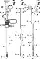
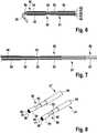
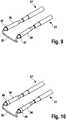
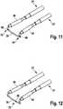
1 ein bipolares medizinisches Instrument gemäß der vorliegenden Erfindung in der Seitenansicht, hier ein Resektoskop;2 Elemente innerhalb des Instruments gemäß1 in der Seitenansicht;3 Elemente innerhalb des Instruments gemäß1 in der Draufsicht;4 die Elemente gemäß2 in perspektivischer Ansicht;5 den vergrößerten Ausschnitt A aus4 ;6 einen Querschnitt in Längsrichtung der Elemente gemäß2 im distalen Abschnitt des Instruments;7 einen Querschnitt in Längsrichtung der Elemente gemäß2 im proximalen Abschnitt des Instruments;8 eine Schnittdarstellung des Schnitts B aus der5 ;9 eine erste alternative Ausgestaltung der Neutralelektrode des bipolaren medizinischen Instruments;10 eine zweite alternative Ausgestaltung der Neutralelektrode des bipolaren medizinischen Instruments;11 eine erste alternative Ausgestaltung der Aktivelektrode des bipolaren medizinischen Instruments; und12 eine zweite alternative Ausgestaltung der Aktivelektrode des bipolaren medizinischen Instruments.
1 a bipolar medical instrument according to the present invention in side view, here a resectoscope;2 Items within the instrument as per1 in side view;3 Items within the instrument as per1 in top view;4 the elements according to2 in perspective view;5 the enlarged section A4 ;6 a cross-section in the longitudinal direction of the elements according to FIG2 in the distal section of the instrument;7 a cross-section in the longitudinal direction of the elements according to FIG2 in the proximal section of the instrument;8th a sectional view of section B from FIG5 ;9 a first alternative embodiment of the neutral electrode of the bipolar medical instrument;10 a second alternative embodiment of the neutral electrode of the bipolar medical instrument;11 a first alternative embodiment of the active electrode of the bipolar medical instrument; and12 a second alternative embodiment of the active electrode of the bipolar medical instrument.
Das Instrument 10 erstreckt sich entlang einer Längsrichtung 12 von einem proximalen Ende 14 zu einem distalen Ende 16. Das Instrument 10 ist hier im eingefahrenen Zustand gezeigt. Es ist zu erkennen, dass sich sowohl eine Aktivelektrode 30 (siehe
Am proximalen Ende 14 des ersten Elektrodenträgerteils 21 sind ein erster Kontaktierbereich 60 der ersten Zuleitung 40 und ein zweiter Kontaktierbereich 62 der zweiten Zuleitung 42 ausgebildet ist, die entlang der Längsrichtung 12 versetzt zueinander angeordnet sind. Bei dieser Ausgestaltung weisen die Kontaktierbereiche 60, 62 jeweils eine zylinderförmige Oberfläche aufweisen. Entsprechendes gilt für einen dritten Kontaktierbereich 64 und einen vierten Kontaktierbereich 66 des zweiten Elektrodenträgerteils 21'.A first contacting
Ferner ist symbolisch dargestellt, wie die elektrisch aktiven Elemente des Instruments 10 an einen Hochfrequenzgenerator 26 angeschlossen werden können, wobei der Hochfrequenzgenerator 26 einen ersten hier eine Ausgangsleistung von mindestens 200 W abgeben kann. Der erste Elektrodenträgerteil 21 ist mit einem ersten Port 27 des Hochfrequenzgenerators 26 verbunden, und der zweite Elektrodenträgerteil 21' ist mit einem zweiten Port 27' des Hochfrequenzgenerators 26 verbunden.Furthermore, it is shown symbolically how the electrically active elements of the instrument 10 can be connected to a high-
Zudem ist auch ein Winkel α zwischen den beiden Neutralelektrodenflächen 34, 36, genauer, zwischen den beiden Längserstreckungen der Neutralelektrodenflächen 34, 36, dargestellt. Die Neutralelektrodenflächen 34, 36 können aber auch parallel zu einander liegen, wobei dann α = 0° gilt.In addition, an angle α between the two neutral electrode surfaces 34, 36, more precisely, between the two longitudinal extents of the neutral electrode surfaces 34, 36, is also shown. However, the neutral electrode surfaces 34, 36 can also lie parallel to one another, in which case α=0° applies.
Die erste Neutralelektrodenfläche 34 ist mit einer zweiten Zuleitung 42 verbunden, die vom proximalen Ende 14 zur ersten Neutralelektrodenfläche 34 führt, und die zweite Neutralelektrodenfläche 36 ist mit einer dritten Zuleitung 44 (siehe
Die erste Neutralelektrodenfläche 34 und die zweite Neutralelektrodenfläche 36 sind am distalen Ende 16 nicht elektrisch verbunden. Dabei kann die Ausgestaltung auch so gewählt werden, dass die erste Neutralelektrodenfläche 34 und die zweite Neutralelektrodenfläche 36 nur am proximalen Ende 14 elektrisch verbunden sind, zum Beispiel, siehe
Die erste Neutralelektrodenfläche 34 oder die zweite elektrische Zuleitung 42 in einem zweiten Abschnitt 50 in proximaler Richtung, als auf das proximale Ende 14 zu, konisch zulaufen. Entsprechend gilt, auch wenn nicht gezeigt, dass die zweite Neutralelektrodenfläche 36 oder die dritte elektrische Zuleitung 42 in dem zweiten Abschnitt 50 in proximaler Richtung konisch zulaufen. Bei der gezeigten Ausgestaltung umschließt die erste Neutralelektrodenfläche 34 die erste elektrische Zuleitung 40.The first
Die zweite elektrische Zuleitung 42 in einer rohrförmigen Isolierung 52 geführt ist, die optional von einem metallischen Röhrchen 54 umschlossen ist. Ein Durchmesser der rohrförmigen Isolierung 52 oder, wenn vorhanden, ein Durchmesser des metallischen Röhrchens 54 ist hier so gewählt, dass er zumindest in etwa dem Durchmesser der ersten Neutralelektrodenfläche 34 entspricht.The second
Es ist ferner zu erkennen, dass in distaler Richtung vor der ersten Neutralelektrodenfläche 34 ein rohrförmiges Isolierstück 56 angeordnet ist, das die zweite Zuleitung 42 umschließt, wobei das Isolierstück 56 hier zudem von der ersten Neutralelektrodenfläche 34 umschlossen ist.It can also be seen that in the distal direction in front of the first
ZITATE ENTHALTEN IN DER BESCHREIBUNGQUOTES INCLUDED IN DESCRIPTION
Diese Liste der vom Anmelder aufgeführten Dokumente wurde automatisiert erzeugt und ist ausschließlich zur besseren Information des Lesers aufgenommen. Die Liste ist nicht Bestandteil der deutschen Patent- bzw. Gebrauchsmusteranmeldung. Das DPMA übernimmt keinerlei Haftung für etwaige Fehler oder Auslassungen.This list of documents cited by the applicant was generated automatically and is included solely for the better information of the reader. The list is not part of the German patent or utility model application. The DPMA assumes no liability for any errors or omissions.
Zitierte PatentliteraturPatent Literature Cited
- DE 2521719 [0003, 0011]DE 2521719 [0003, 0011]
- WO 9916371 A1 [0012]WO 9916371 A1 [0012]
- EP 1163886 A2 [0013]EP 1163886 A2 [0013]
- US 9474438 B2 [0014]US9474438B2 [0014]
- EP 1567079 B1 [0052]EP 1567079 B1 [0052]
Claims (15)
Translated fromGermanPriority Applications (1)
| Application Number | Priority Date | Filing Date | Title |
|---|---|---|---|
| DE102020118265.1ADE102020118265A1 (en) | 2020-07-10 | 2020-07-10 | Medical instrument and electrosurgical system |
Applications Claiming Priority (1)
| Application Number | Priority Date | Filing Date | Title |
|---|---|---|---|
| DE102020118265.1ADE102020118265A1 (en) | 2020-07-10 | 2020-07-10 | Medical instrument and electrosurgical system |
Publications (1)
| Publication Number | Publication Date |
|---|---|
| DE102020118265A1true DE102020118265A1 (en) | 2022-01-13 |
Family
ID=79019925
Family Applications (1)
| Application Number | Title | Priority Date | Filing Date |
|---|---|---|---|
| DE102020118265.1APendingDE102020118265A1 (en) | 2020-07-10 | 2020-07-10 | Medical instrument and electrosurgical system |
Country Status (1)
| Country | Link |
|---|---|
| DE (1) | DE102020118265A1 (en) |
Cited By (3)
| Publication number | Priority date | Publication date | Assignee | Title |
|---|---|---|---|---|
| DE102023100244A1 (en)* | 2023-01-05 | 2024-07-11 | Olympus Winter & Ibe Gmbh | Electrode for an electrosurgical hand instrument |
| DE102023108868A1 (en)* | 2023-04-06 | 2024-10-10 | Bowa-Electronic Gmbh & Co. Kg | Electrode unit for an electrosurgical instrument and electrosurgical instrument |
| DE102023129912A1 (en) | 2023-10-30 | 2025-04-30 | Henke-Sass, Wolf Gmbh | Bipolar electrode for a resectoscope and resectoscope with such a bipolar electrode |
Citations (8)
| Publication number | Priority date | Publication date | Assignee | Title |
|---|---|---|---|---|
| DE2521719A1 (en) | 1975-05-15 | 1976-11-25 | Delma Elektro Med App | ELECTROSURGICAL DEVICE |
| JPH06191A (en) | 1992-06-20 | 1994-01-11 | Kazuo Kato | Coaxial bipolar catheter for high-frequency catheter abrasion and junction coaxial cable |
| WO1999016371A1 (en) | 1997-09-30 | 1999-04-08 | Boston Scientific Corporation | Apparatus for electro-surgical tissue removal |
| EP1163886A2 (en) | 2000-06-16 | 2001-12-19 | Olympus Winter & Ibe Gmbh | HF resectoscope |
| EP1567079B1 (en) | 2002-12-06 | 2006-08-16 | Karl Storz GmbH & Co. KG | Bipolar medical instrument and electrosurgical system comprising one such instrument |
| DE102013109505A1 (en) | 2013-08-30 | 2015-03-05 | Karl Storz Gmbh & Co. Kg | Medical instrument and electrosurgical system |
| US9474438B2 (en) | 2010-05-28 | 2016-10-25 | Gyrus Acmi, Inc. | Continuous flow endoscope systems |
| EP2767250B1 (en) | 2013-02-19 | 2018-07-25 | Covidien LP | Electrosurgical electrodes |
- 2020
- 2020-07-10DEDE102020118265.1Apatent/DE102020118265A1/enactivePending
Patent Citations (8)
| Publication number | Priority date | Publication date | Assignee | Title |
|---|---|---|---|---|
| DE2521719A1 (en) | 1975-05-15 | 1976-11-25 | Delma Elektro Med App | ELECTROSURGICAL DEVICE |
| JPH06191A (en) | 1992-06-20 | 1994-01-11 | Kazuo Kato | Coaxial bipolar catheter for high-frequency catheter abrasion and junction coaxial cable |
| WO1999016371A1 (en) | 1997-09-30 | 1999-04-08 | Boston Scientific Corporation | Apparatus for electro-surgical tissue removal |
| EP1163886A2 (en) | 2000-06-16 | 2001-12-19 | Olympus Winter & Ibe Gmbh | HF resectoscope |
| EP1567079B1 (en) | 2002-12-06 | 2006-08-16 | Karl Storz GmbH & Co. KG | Bipolar medical instrument and electrosurgical system comprising one such instrument |
| US9474438B2 (en) | 2010-05-28 | 2016-10-25 | Gyrus Acmi, Inc. | Continuous flow endoscope systems |
| EP2767250B1 (en) | 2013-02-19 | 2018-07-25 | Covidien LP | Electrosurgical electrodes |
| DE102013109505A1 (en) | 2013-08-30 | 2015-03-05 | Karl Storz Gmbh & Co. Kg | Medical instrument and electrosurgical system |
Cited By (4)
| Publication number | Priority date | Publication date | Assignee | Title |
|---|---|---|---|---|
| DE102023100244A1 (en)* | 2023-01-05 | 2024-07-11 | Olympus Winter & Ibe Gmbh | Electrode for an electrosurgical hand instrument |
| DE102023108868A1 (en)* | 2023-04-06 | 2024-10-10 | Bowa-Electronic Gmbh & Co. Kg | Electrode unit for an electrosurgical instrument and electrosurgical instrument |
| DE102023129912A1 (en) | 2023-10-30 | 2025-04-30 | Henke-Sass, Wolf Gmbh | Bipolar electrode for a resectoscope and resectoscope with such a bipolar electrode |
| EP4548869A1 (en)* | 2023-10-30 | 2025-05-07 | Henke-Sass, Wolf GmbH | Bipolar electrode for a resectoscope and resectoscope having such a bipolar electrode |
Similar Documents
| Publication | Publication Date | Title |
|---|---|---|
| DE102013109505B4 (en) | Medical instrument and electrosurgical system | |
| DE602005001776T2 (en) | Bipolar electrosurgical sling | |
| DE60024877T2 (en) | ELEKTROKAUTERISATIONSKATHETER | |
| EP1567079B1 (en) | Bipolar medical instrument and electrosurgical system comprising one such instrument | |
| DE69629501T2 (en) | SLEEVE ELECTRODES FOR ELECTROCAUTERIZING PROBE FOR USE IN A RESECTOSCOPE | |
| EP0866672B1 (en) | Arrangement for electrothermal treatment of the human or animal body | |
| DE69730049T2 (en) | CUTTING BLADES FOR AN ELECTRIC CAUCATION ENGINE | |
| EP2451374B1 (en) | Electrosurgical instrument and method for producing an electrosurgical instrument | |
| WO2001089403A1 (en) | Electrode configuration for a surgical instrument | |
| EP0871405A1 (en) | Bipolar high-frequency surgical instrument | |
| DE102020118265A1 (en) | Medical instrument and electrosurgical system | |
| DE69921256T2 (en) | Electrocoagulation device for varices | |
| EP3649974B1 (en) | Electrode arrangement for a bipolar resectoscope and resectoscope | |
| DE10354275A1 (en) | High-frequency knife for cutting living tissue has protrusion whose front end comprises electrical insulator which covers electrode so that edge portion at side of base of electrode extends to side of protrusion | |
| EP3141203A1 (en) | Ablation device for large-scale mucosa ablation | |
| WO2012003966A1 (en) | Electrode arrangement | |
| DE102019220537A1 (en) | Devices for enucleation of intracorporeal tissue areas | |
| DE10354830B4 (en) | High frequency cutter | |
| DE102004042998A1 (en) | Electrosurgical probe | |
| DE102005042312A1 (en) | High frequency treatment instrument for an endoscope | |
| DE202008004064U1 (en) | Ablation device with reduced nerve stimulation | |
| DE102018125287A1 (en) | Resectoscope with shaft tube electrode instrument | |
| DE102017007732B4 (en) | Surgical instrument for flexible endoscope | |
| DE102020124917A1 (en) | Medical instrument for minimally invasive removal of biological material from a human or animal body | |
| EP3708103A1 (en) | Electrode instrument and resectoscope with gripping function |
Legal Events
| Date | Code | Title | Description |
|---|---|---|---|
| R012 | Request for examination validly filed | ||
| R016 | Response to examination communication |