DE102020117713A1 - Lithotripsy device and method of operating a lithotripsy device - Google Patents
Lithotripsy device and method of operating a lithotripsy deviceDownload PDFInfo
- Publication number
- DE102020117713A1 DE102020117713A1DE102020117713.5ADE102020117713ADE102020117713A1DE 102020117713 A1DE102020117713 A1DE 102020117713A1DE 102020117713 ADE102020117713 ADE 102020117713ADE 102020117713 A1DE102020117713 A1DE 102020117713A1
- Authority
- DE
- Germany
- Prior art keywords
- sonotrode
- lithotripsy device
- ultrasonic
- lithotripsy
- unit
- Prior art date
- Legal status (The legal status is an assumption and is not a legal conclusion. Google has not performed a legal analysis and makes no representation as to the accuracy of the status listed.)
- Granted
Links
Images


Classifications
- A—HUMAN NECESSITIES
- A61—MEDICAL OR VETERINARY SCIENCE; HYGIENE
- A61B—DIAGNOSIS; SURGERY; IDENTIFICATION
- A61B17/00—Surgical instruments, devices or methods
- A61B17/22—Implements for squeezing-off ulcers or the like on inner organs of the body; Implements for scraping-out cavities of body organs, e.g. bones; for invasive removal or destruction of calculus using mechanical vibrations; for removing obstructions in blood vessels, not otherwise provided for
- A61B17/22004—Implements for squeezing-off ulcers or the like on inner organs of the body; Implements for scraping-out cavities of body organs, e.g. bones; for invasive removal or destruction of calculus using mechanical vibrations; for removing obstructions in blood vessels, not otherwise provided for using mechanical vibrations, e.g. ultrasonic shock waves
- A61B17/22012—Implements for squeezing-off ulcers or the like on inner organs of the body; Implements for scraping-out cavities of body organs, e.g. bones; for invasive removal or destruction of calculus using mechanical vibrations; for removing obstructions in blood vessels, not otherwise provided for using mechanical vibrations, e.g. ultrasonic shock waves in direct contact with, or very close to, the obstruction or concrement
- A—HUMAN NECESSITIES
- A61—MEDICAL OR VETERINARY SCIENCE; HYGIENE
- A61B—DIAGNOSIS; SURGERY; IDENTIFICATION
- A61B17/00—Surgical instruments, devices or methods
- A61B17/22—Implements for squeezing-off ulcers or the like on inner organs of the body; Implements for scraping-out cavities of body organs, e.g. bones; for invasive removal or destruction of calculus using mechanical vibrations; for removing obstructions in blood vessels, not otherwise provided for
- A61B17/22004—Implements for squeezing-off ulcers or the like on inner organs of the body; Implements for scraping-out cavities of body organs, e.g. bones; for invasive removal or destruction of calculus using mechanical vibrations; for removing obstructions in blood vessels, not otherwise provided for using mechanical vibrations, e.g. ultrasonic shock waves
- A61B2017/22005—Effects, e.g. on tissue
- A61B2017/22011—Combined types of vibration, e.g. ultrasonic and electrohydraulic
- A—HUMAN NECESSITIES
- A61—MEDICAL OR VETERINARY SCIENCE; HYGIENE
- A61B—DIAGNOSIS; SURGERY; IDENTIFICATION
- A61B17/00—Surgical instruments, devices or methods
- A61B17/22—Implements for squeezing-off ulcers or the like on inner organs of the body; Implements for scraping-out cavities of body organs, e.g. bones; for invasive removal or destruction of calculus using mechanical vibrations; for removing obstructions in blood vessels, not otherwise provided for
- A61B17/22004—Implements for squeezing-off ulcers or the like on inner organs of the body; Implements for scraping-out cavities of body organs, e.g. bones; for invasive removal or destruction of calculus using mechanical vibrations; for removing obstructions in blood vessels, not otherwise provided for using mechanical vibrations, e.g. ultrasonic shock waves
- A61B17/22012—Implements for squeezing-off ulcers or the like on inner organs of the body; Implements for scraping-out cavities of body organs, e.g. bones; for invasive removal or destruction of calculus using mechanical vibrations; for removing obstructions in blood vessels, not otherwise provided for using mechanical vibrations, e.g. ultrasonic shock waves in direct contact with, or very close to, the obstruction or concrement
- A61B2017/22014—Implements for squeezing-off ulcers or the like on inner organs of the body; Implements for scraping-out cavities of body organs, e.g. bones; for invasive removal or destruction of calculus using mechanical vibrations; for removing obstructions in blood vessels, not otherwise provided for using mechanical vibrations, e.g. ultrasonic shock waves in direct contact with, or very close to, the obstruction or concrement the ultrasound transducer being outside patient's body; with an ultrasound transmission member; with a wave guide; with a vibrated guide wire
Landscapes
- Health & Medical Sciences (AREA)
- Surgery (AREA)
- Engineering & Computer Science (AREA)
- Life Sciences & Earth Sciences (AREA)
- Biomedical Technology (AREA)
- Nuclear Medicine, Radiotherapy & Molecular Imaging (AREA)
- Vascular Medicine (AREA)
- Orthopedic Medicine & Surgery (AREA)
- Mechanical Engineering (AREA)
- Heart & Thoracic Surgery (AREA)
- Medical Informatics (AREA)
- Molecular Biology (AREA)
- Animal Behavior & Ethology (AREA)
- General Health & Medical Sciences (AREA)
- Public Health (AREA)
- Veterinary Medicine (AREA)
- Surgical Instruments (AREA)
Abstract
Translated fromGerman
Description
Translated fromGermanStand der TechnikState of the art
Die Erfindung betrifft eine Lithotripsievorrichtung, insbesondere eine intrakorporale Lithotripsievorrichtung, nach dem Oberbegriff des Anspruchs 1 sowie ein Verfahren zum Betrieb einer Lithotripsievorrichtung nach dem Oberbegriff des Anspruchs 19.The invention relates to a lithotripsy device, in particular an intracorporeal lithotripsy device, according to the preamble of claim 1 and a method for operating a lithotripsy device according to the preamble of claim 19.
Aus dem Stand der Technik ist bereits eine Lithotripsievorrichtung bekannt, welche eine Sonotrode, welche einen Sonotrodenkopf und eine Sonotrodenspitze umfasst, und ein Ultraschallhorn aufweist. Das Ultraschallhorn ist dazu eingerichtet, entlang einer Übertragungsrichtung Ultraschallwellen auf den Sonotrodenkopf zu übertragen und zu fokussieren. Ferner ist die Sonotrode dazu eingerichtet, die Ultraschallwellen entlang derselben Übertragungsrichtung die Ultraschallwellen von dem Sonotrodenkopf zu der Sonotrodenspitze zu leiten.A lithotripsy device is already known from the prior art, which has a sonotrode, which comprises a sonotrode head and a sonotrode tip, and an ultrasonic horn. The ultrasonic horn is set up to transmit and focus ultrasonic waves along a transmission direction onto the sonotrode head. Furthermore, the sonotrode is set up to guide the ultrasonic waves along the same transmission direction, the ultrasonic waves from the sonotrode head to the sonotrode tip.
Die Aufgabe der Erfindung besteht insbesondere darin, eine gattungsgemäße Vorrichtung mit verbesserten Eigenschaften hinsichtlich einer Effizienz, insbesondere einer Bauraumeffizienz und/oder einer Bauteileffizienz bereitzustellen. Die Aufgabe wird erfindungsgemäß durch die Merkmale des Patentanspruchs 1 bzw. 19 gelöst, während vorteilhaft Ausgestaltung und Weiterbildung der Erfindung den Unteransprüchen entnommen werden können.The object of the invention is in particular to provide a generic device with improved properties in terms of efficiency, in particular installation space efficiency and/or component efficiency. The object is achieved according to the invention by the features of patent claim 1 and 19, respectively, while the advantageous embodiment and further development of the invention can be found in the dependent claims.
Vorteile der ErfindungAdvantages of the Invention
Die Erfindung geht aus von einer Lithotripsievorrichtung, insbesondere einer intrakorporalen Lithotripsievorrichtung, mit wenigstens einer Sonotrode, welche zur Aufnahme von Ultraschallwellen wenigstens einen Sonotrodenkopf und zur Beaufschlagung von Konkrementen wenigstens eine Sonotrodenspitze, welche mit dem Sonotrodenkopf verbunden ist, umfasst, und mit einem Ultraschallhorn.The invention is based on a lithotripsy device, in particular an intracorporeal lithotripsy device, with at least one sonotrode, which comprises at least one sonotrode head for receiving ultrasonic waves and at least one sonotrode tip, which is connected to the sonotrode head, for impinging on calculus, and with an ultrasonic horn.
Es wird vorgeschlagen, dass das Ultraschallhorn dazu eingerichtet ist, entlang einer ersten Übertragungsrichtung Ultraschallwellen zumindest mittelbar auf den Sonotrodenkopf zu übertragen und zu fokussieren, und die Sonotrode dazu eingerichtet ist, entlang wenigstens einer zweiten Übertragungsrichtung, die von der ersten Übertragungsrichtung verschieden ist, die Ultraschallwellen vom Sonotrodenkopf zur Sonotrodenspitze zu übertragen.It is proposed that the ultrasonic horn be set up to transmit and focus ultrasonic waves at least indirectly onto the sonotrode head along a first transmission direction, and the sonotrode be set up to transmit the ultrasonic waves along at least a second transmission direction, which is different from the first transmission direction from the sonotrode head to the sonotrode tip.
Hierdurch kann vorteilhaft eine Effizienz verbessert werden. Insbesondere kann eine kompakte Anordnung von Bauteilen realisiert werden, wodurch sich weitere Baugruppen und Komponenten eines Lithotripters, wie insbesondere eine Stoßimpulseinheit, zur kombinierten Lithotripsie einbinden lassen. Besonders vorteilhaft kann eine Energieübertragung von Energie, bereitstellenden Komponenten auf die Sonotrode verbessert werden, wie beispielsweise in Form von Ultraschallwellen und/oder Stoßimpulsen. Besonders vorteilhaft kann ein modularer Aufbau erzielt werden, welcher je nach Kombination bzw. Betrieb einzelner Module, sowohl den Einzelbetrieb nur mit Ultraschallwellen oder einen Kombinationsbetrieb mit Ultraschallwellen und Stoßimpulsen erlaubt. Dies kann insbesondere zur Beseitigung von besonders großen oder festen Konkrementen von Vorteil sein.As a result, efficiency can advantageously be improved. In particular, a compact arrangement of components can be implemented, as a result of which further assemblies and components of a lithotripter, such as in particular a shock pulse unit, can be integrated for combined lithotripsy. Energy transfer from energy-providing components to the sonotrode can be improved particularly advantageously, for example in the form of ultrasonic waves and/or impact pulses. A modular design can be achieved in a particularly advantageous manner, which, depending on the combination or operation of individual modules, allows both individual operation using only ultrasonic waves or combined operation with ultrasonic waves and shock pulses. This can be of particular advantage when removing particularly large or solid calculi.
Unter einer „Lithotripsievorrichtung“ soll insbesondere ein vorzugsweise funktionsfähiger Bestandteil, beispielsweise einer Unterbaugruppe und/oder eine Konstruktions- und/oder eine Funktionskomponente eines Lithotripters verstanden werden. Vorzugsweise kann die Lithotripsievorrichtung den Lithotripter zumindest teilweise, bevorzugt zumindest zu einem Großteil und besonders bevorzugt vollständig ausbilden. Die Lithotripsievorrichtung ist insbesondere zu einer Zertrümmerung von Konkrementen eingerichtet. Unter „Konkrementen“ sollen insbesondere sich in Körpern durch Abscheidung entstehende feste Gebilde verstanden werden, welche zumindest teilweise, vorzugsweise zumindest zu einem Großteil und besonders bevorzugt vollständig aus Salzen bestehen, wie beispielsweise Nierensteine, Gallensteine, Harnsteine, Speichelsteine oder dergleichen. Unter einer „intrakorporalen Lithotripsievorrichtung“ soll insbesondere eine Lithotripsievorrichtung verstanden werden, welche dazu eingerichtet ist zumindest teilweise und vorzugsweise zumindest zu einem Großteil in eine insbesondere künstliche und/oder natürliche Öffnung, insbesondere Körperöffnung, eingeführt zu werden, um dort angesammelte Konkremente zu zertrümmern und/oder zu entfernen. Unter „eingerichtet“ soll insbesondere speziell programmiert, vorgesehen, ausgelegt, ausgebildet und/oder ausgestattet verstanden werden. Darunter, dass ein Bauteil zu einer bestimmten Funktion eingerichtet ist, soll insbesondere verstanden werden, dass das Bauteil diese bestimmte Funktion in zumindest einen Anwendungs- und/oder Betriebszustand erfüllt und/oder ausführt. Unter dem Ausdruck „zumindest zu einem Großteil“ soll dabei insbesondere dabei zumindest zu 55%, vorzugsweise zumindest zu 65%, bevorzugst zumindest zu 70% und besonders bevorzugt zumindest zu 85% und ganz besonders bevorzugt zumindest zu 95%, sowie vorteilhaft vollständig verstanden werden und zwar insbesondere mit Bezug auf ein Volumen und/oder eine Masse eines Bauteilts. Unter einer „Sonotrode“ soll insbesondere eine stab-, röhren- und/oder schlauchförmige Sonde verstanden werden, welche zur Untersuchung und/oder Behandlung eingerichtet ist. Vorzugsweise ist die Sonotrode als eine intrakorporale Sonotrode ausgebildet. Unter einer „intrakorporalen Sonotrode“ soll insbesondere eine Sonotrode verstanden werden, welche dazu eingerichtet ist, zumindest teilweise, vorzugsweise zumindest zu einem Großteil und besonders bevorzugt vollständig in eine insbesondere künstliche und/oder natürliche Öffnung, insbesondere Körperöffnung, eingeführt zu werden, um beispielsweise dort angesammelte Konkremente zu zertrümmern und/oder zu entfernen. Die Sonotrode weist insbesondere zumindest eine Sonotrodenspitze auf, welche dazu eingerichtet ist, Konkremente unmittelbar zu kontaktieren sowie Ultraschallwellen auf diese zu übertragen. Anstelle einer unmittelbaren Beaufschlagung kann auch eine zumindest mittelbare Beaufschlagung der Konkremente durch die Sonotrode denkbar sein. Unter „zumindest mittelbar“ soll insbesondere indirekt, aber vorzugsweise auch direkt, also insbesondere unmittelbar, verstanden werden. Der Sonotrodenkopf und die Sonotrodenspitze der Sonotrode sind vorzugsweise voneinander separat ausgebildet. Alternativ könnten Sonotrodenkopf und Sonotrodenspitze einstückig ausgebildet und/oder verbunden sein. Darunter, dass „ein Bauteil und ein weiteres Bauteil zumindest teilweise einstückig ausgebildet und/oder verbunden sind“, soll insbesondere verstanden werden, dass zumindest ein Element und/oder Teil des Bauteils und zumindest ein Element und/oder ein Teil des weiteren Bauteils einteilig miteinander ausgebildet und/oder verbunden sind. Unter „einstückig“ soll insbesondere zumindest stoffschlüssig verbunden, wie beispielsweise durch einen Schweißprozess, einen Klebeprozess, einen Anspritzprozess und/oder einen anderen dem Fachmann als sinnvoll erscheinenden Prozess und/oder vorteilhaft in einem Stück geformt verstanden werden, wie beispielsweise durch eine Herstellung aus einem Guss und/oder durch eine Herstellung in einem Ein- oder Mehrkomponentenspritzverfahren und vorteilhaft aus einem einzelnen Rohling. Die Lithotripsievorrichtung weist insbesondere wenigstens einen Ultraschallgenerator auf. Der Ultraschallgenerator ist dazu eingerichtet, die Ultraschallwellen bereitzustellen und/oder zu erzeugen. Zur Erzeugung der Ultraschallwellen weist der Ultraschallgenerator wenigstens einen, vorzugsweise zumindest zwei, besonders bevorzugst zumindest drei und ganz besonders bevorzugt eine Vielzahl von Ultraschallaktoren auf. Der Ultraschallaktor ist vorzugsweise als ein Piezoaktor ausgebildet. Es sind jedoch auch andere, insbesondere mechanische Ausgestaltungen des Ultraschallaktors denkbar. Insbesondere für den Fall, dass der Ultraschallgenerator zumindest zwei Ultraschallaktoren umfasst, liegen diese zumindest mittelbar aneinander an, um vorteilhaft eine Intensität der erzeugten Ultraschallwellen zu erhöhen. Der Ultraschallgenerator ist insbesondere mit dem Ultraschallhorn wirkverbunden. Vorzugseise liegt das Ultraschallhorn zumindest mittelbar an dem Ultraschallgenerator an. Bevorzugt besteht das Ultraschallhorn zumindest teilweise, vorzugsweise zumindest zu einem Großteil und besonders bevorzugt vollständig aus Metall, wie beispielsweise Eisen, Titan, Stahl oder einer Metalllegion. Unter „Ultraschallwellen“ sollen insbesondere Schallwellen verstanden werden, welche oberhalb eines für den Menschen wahrnehmbaren Hörfrequenzbereichs liegen. Im vorliegenden Fall weisen die Ultraschallwelle insbesondere eine Ultraschallfrequenz von zumindest 10 kHz, vorzugsweise zumindest 15 kHz und besonders bevorzugt von zumindest 20 kHz und/oder von höchstens 100 kHz, vorzugsweise von höchstens 80 kHz und besonders bevorzugt von höchstens 56 kHz auf. Ganz besonders bevorzugt beträgt die Ultraschallfrequenz der Ultraschallwellen einen Wert zwischen 22 kHz und 55 kHz. Unter einer „Übertragungsrichtung“ soll insbesondere eine Richtung verstanden werden, welche eine Übertragung von Ultraschallwellen entlang eines Bauteils entspricht. Insbesondere ist die erste Übertragungsrichtung zumindest im Wesentlichen parallel zu einer Haupterstreckungsrichtung des Ultraschallhorn. Ferner ist insbesondere die zweite Übertragungsrichtung zumindest im Wesentlichen parallel zu einer Haupterstreckungsrichtung der Sonotrode. Unter einer „Haupterstreckungsrichtung“ eines Bauteils soll dabei insbesondere eine Richtung verstanden werden, welche parallel zu einer längsten Kante eines kleinsten gedachten Quaders verläuft, welcher das Bauteil gerade noch vollständig umschließt. Unter „zumindest im Wesentlichen parallel“ soll insbesondere das Einschließen eines Winkels von 0°verstanden werden, wobei insbesondere dieser Winkel eine Abweichung von höchstens 15°, vorzugsweise von höchstens 10° und besonders bevorzug von höchstens 5° aufweisen kann.A “lithotripsy device” is to be understood in particular as a preferably functional component, for example a subassembly and/or a structural and/or a functional component of a lithotripter. The lithotripsy device can preferably form the lithotripter at least partially, preferably at least to a large extent and particularly preferably completely. The lithotripsy device is designed in particular to break up calculi. “Concretions” are to be understood in particular as solid structures formed in bodies by precipitation, which consist at least partially, preferably at least to a large extent and particularly preferably completely of salts, such as kidney stones, gallstones, urinary stones, salivary stones or the like. An “intracorporeal lithotripsy device” should be understood to mean, in particular, a lithotripsy device which is set up to be inserted at least partially and preferably at least to a large extent into an in particular artificial and/or natural opening, in particular a body opening, in order to shatter calculus that has accumulated there and/or or to remove. “Established” should be understood to mean, in particular, specially programmed, provided, designed, trained and/or equipped. The fact that a component is set up for a specific function is to be understood in particular to mean that the component fulfills and/or executes this specific function in at least one application and/or operating state. The expression “at least to a large extent” is to be understood here in particular as at least 55%, preferably at least 65%, preferably at least 70% and particularly preferably at least 85% and very particularly preferably at least 95%, and advantageously completely in particular with reference to a volume and/or a mass of a component. A "sonotrode" is to be understood in particular as a rod-, tube- and/or hose-shaped probe which is set up for examination and/or treatment. Preferably, the sonotrode is an intracorporeal one Trained sonotrode. An “intracorporeal sonotrode” is to be understood in particular as a sonotrode which is designed to be inserted at least partially, preferably at least to a large extent and particularly preferably completely into an in particular artificial and/or natural opening, in particular a body opening, in order to be inserted there, for example to break up and/or remove accumulated calculus. In particular, the sonotrode has at least one sonotrode tip, which is set up to directly contact calculi and to transmit ultrasonic waves to them. Instead of direct exposure, at least indirect exposure of the calculus to the sonotrode can also be conceivable. “At least indirectly” is to be understood in particular as indirect, but preferably also directly, that is to say in particular directly. The sonotrode head and the sonotrode tip of the sonotrode are preferably designed separately from one another. Alternatively, the sonotrode head and the sonotrode tip could be designed and/or connected in one piece. The fact that “a component and a further component are at least partially integrally formed and/or connected” is to be understood in particular as meaning that at least one element and/or part of the component and at least one element and/or part of the further component are integral with one another are formed and / or connected. “In one piece” is to be understood in particular as being at least cohesively connected, such as by a welding process, an adhesive process, an injection molding process and/or another process that appears sensible to the person skilled in the art and/or advantageously formed in one piece, such as by production from a Casting and/or by manufacturing in a one-component or multi-component injection molding process and advantageously from a single blank. In particular, the lithotripsy device has at least one ultrasound generator. The ultrasonic generator is set up to provide and/or generate the ultrasonic waves. In order to generate the ultrasonic waves, the ultrasonic generator has at least one, preferably at least two, particularly preferably at least three and very particularly preferably a large number of ultrasonic actuators. The ultrasonic actuator is preferably designed as a piezo actuator. However, other, in particular mechanical, configurations of the ultrasonic actuator are also conceivable. In particular in the event that the ultrasonic generator comprises at least two ultrasonic actuators, these are at least indirectly in contact with one another in order to advantageously increase an intensity of the ultrasonic waves generated. The ultrasonic generator is in particular operatively connected to the ultrasonic horn. The ultrasonic horn is preferably at least indirectly in contact with the ultrasonic generator. The ultrasonic horn preferably consists at least partially, preferably at least to a large extent and particularly preferably entirely of metal, such as iron, titanium, steel or a metal alloy. “Ultrasonic waves” should be understood to mean, in particular, sound waves which are above an audible frequency range that can be heard by humans. In the present case, the ultrasonic wave has an ultrasonic frequency of at least 10 kHz, preferably at least 15 kHz and particularly preferably at least 20 kHz and/or at most 100 kHz, preferably at most 80 kHz and particularly preferably at most 56 kHz. Very particularly preferably, the ultrasonic frequency of the ultrasonic waves is between 22 kHz and 55 kHz. A “direction of transmission” is to be understood in particular as a direction which corresponds to a transmission of ultrasonic waves along a component. In particular, the first transmission direction is at least essentially parallel to a main extension direction of the ultrasonic horn. Furthermore, in particular the second transmission direction is at least essentially parallel to a main extension direction of the sonotrode. A “main extension direction” of a component is to be understood in particular as a direction that runs parallel to a longest edge of an imaginary cuboid that just barely completely encloses the component. “At least essentially parallel” is to be understood in particular as including an angle of 0°, with this angle in particular being able to deviate by at most 15°, preferably at most 10° and particularly preferably at most 5°.
Es ist denkbar, dass die erste Übertragungsrichtung und die zweite Übertragungsrichtung winklig zueinander sind, um beispielsweise einen Schereffekt bei der Beaufschlagung der Konkremente zu erzeugen, wodurch vorteilhaft eine Zerstörung der Konkremente verbessert werden kann. Des Weiteren wird vorgeschlagen, dass die erste Übertragungsrichtung und die zweite Übertragungsrichtung einander entgegengerichtet sind. Hierdurch kann eine Kompaktheit weiter verbessert werden. Vorzugsweise sind die erste Übertragungsrichtung und die zweite Übertragungsrichtung zueinander antiparallel. Die erste Übertragungsrichtung ist insbesondere eine proximale Richtung. Unter einer „proximalen Richtung“ soll insbesondere eine Richtung verstanden werden, welche in Richtung eines Benutzers der Vorrichtung ausgerichtet ist. Die zweite Übertragungsrichtung ist insbesondere eine distale Richtung. Unter einer „distalen Richtung“ soll insbesondere eine Richtung verstanden werden, welche in Richtung eines zu behandelnden Patienten ausgerichtet ist.It is conceivable that the first transmission direction and the second transmission direction are at an angle to one another, for example in order to produce a shearing effect when the calculus is acted upon, as a result of which destruction of the calculus can advantageously be improved. Furthermore, it is proposed that the first direction of transmission and the second direction of transmission are opposite to one another. In this way, compactness can be further improved. The first transmission direction and the second transmission direction are preferably antiparallel to one another. The first transmission direction is in particular a proximal direction. A "proximal direction" is to be understood in particular as a direction which is oriented in the direction of a user of the device. The second transmission direction is in particular a distal direction. A “distal direction” is to be understood in particular as a direction which is oriented in the direction of a patient to be treated.
Es wird zudem vorgeschlagen, dass das Ultraschallhorn sich entlang der ersten Übertragungsrichtung verjüngt. Hierdurch kann vorteilhaft eine Kompaktheit weiter verbessert werden, da derart das Ultraschallhorn weniger Bauraum innerhalb eines Gehäuses benötigt. Auch können hierdurch Ultraschallwellen besser fokussiert werden. Das Ultraschallhorn weist vorzugsweise eine sich insbesondere konkav verjüngende Zylinderform auf.It is also proposed that the ultrasonic horn tapers along the first transmission direction. In this way, compactness can advantageously be further improved, since in this way the ultrasonic horn requires less installation space within a housing. Ultrasonic waves can also be better focused as a result. The ultrasonic horn preferably has a cylindrical shape that tapers in particular in a concave manner.
Um vorteilhaft einen Bauraum weiter zu verringern wird vorgeschlagen, dass das Ultraschallhorn die Sonotrode koaxial umgebend angeordnet ist. Darunter, dass „zwei Bauteile koaxial angeordnet sind“, soll insbesondere verstanden werden, dass beide Bauteile eine identische Haupterstreckungsachse aufweisen. Die Sonotrode weist einen Außendurchmesser auf, welcher im Wesentlichen kleiner ist als ein Außendurchmesser des Ultraschallhorns. Unter dem Ausdruck „im Wesentlichen kleiner“ soll insbesondere verstanden werden wenigstens um 10% kleiner, vorzugsweise um wenigstens 20% kleiner und besonders bevorzugt um wenigstens 30% kleiner.In order to advantageously further reduce installation space, it is proposed that the ultrasonic horn be arranged coaxially surrounding the sonotrode. The fact that “two components are arranged coaxially” is to be understood in particular to mean that both components have an identical main axis of extension. The sonotrode has an outer diameter that is essentially smaller than an outer diameter of the ultrasonic horn. The expression “substantially smaller” should be understood in particular to mean at least 10% smaller, preferably at least 20% smaller and particularly preferably at least 30% smaller.
In einer Ausgestaltung der Erfindung wird vorgeschlagen, dass die Sonotrode das Ultraschallhorn entlang der zweiten Übertragungsrichtung durchstößt. Hierdurch kann vorteilhaft ein Bauraum weiter reduziert werden. Das Ultraschallhorn weist insbesondere eine zu der Sonotrode korrespondierend ausgebildete Ausnehmung auf, innerhalb welcher die Sonotrode zumindest teilweise angeordnet ist.In one embodiment of the invention, it is proposed that the sonotrode pierces the ultrasonic horn along the second transmission direction. As a result, an installation space can advantageously be further reduced. The ultrasonic horn has in particular a recess designed to correspond to the sonotrode, within which the sonotrode is at least partially arranged.
Um eine effiziente Energieübertragung zu gewährleisten und trotzdem wenig Bauraum, insbesondere innerhalb eines Gehäuses der Lithotripsievorrichtung, zu beanspruchen, wird des Weiteren vorgeschlagen, dass eine Haupterstreckung der Sonotrode größer ist als eine Haupterstreckung des Ultraschallhorns. Insbesondere ragt ein Teil der Sonotrode distalseitig über das Ultraschallhorn hinaus. Besonders bevorzugt ragt die Ultraschallspitze über das Ultraschallhorn hinaus. Insbesondere liegt der Sonotrodenkopf innerhalb eines Bereichs des Ultraschallhorns. Die Haupterstreckung der Sonotrode ist insbesondere zumindest um 15%, vorzugsweise zumindest um 30% und besonders bevorzugt zumindest um 45% größer als eine Haupterstreckung des Ultraschallhorns.In order to ensure efficient energy transfer and still take up little installation space, in particular within a housing of the lithotripsy device, it is also proposed that a main extent of the sonotrode is greater than a main extent of the ultrasonic horn. In particular, part of the sonotrode projects beyond the ultrasonic horn on the distal side. The ultrasonic tip particularly preferably protrudes beyond the ultrasonic horn. In particular, the sonotrode head lies within a region of the ultrasonic horn. The main extension of the sonotrode is in particular at least 15%, preferably at least 30% and particularly preferably at least 45% greater than a main extension of the ultrasonic horn.
Des Weiteren wird vorgeschlagen, dass die Lithotripsievorrichtung eine Koppeleinheit umfasst, welche zu einer Beaufschlagung der Sonotrode dazu eingerichtet ist, die Sonotrode mit einer Stoßimpulseinheit zu koppeln. Es kann vorteilhaft ein modularer Aufbau erzielt werden, wobei insbesondere verschiedene Komponenten der Lithotripsievorrichtung abhängig von einer Betriebsart miteinander koppelbar sind. Unter einer „Koppeleinheit“ soll insbesondere eine Einheit verstanden werden, welche dazu eingerichtet ist, zumindest zwei weitere Bauteile miteinander wirkverbunden zu koppeln. Dazu kann die Koppeleinheit zu einer form- und/oder kraftschlüssigen Verbindung eingerichtet sein. Insbesondere weist die Lithotripsievorrichtung die Stoßimpulseinheit auf. Unter einer „Stoßimpulseinheit“ soll insbesondere eine Einheit verstanden werden, welche zur Bereitstellung von Stoßimpulsen wenigstens ein beweglich gelagertes Projektil umfasst, welches dazu eingerichtet ist, die Sonotrode zumindest mittelbar mit Stoßimpulsen zu beaufschlagen. Die Stoßimpulseinheit ist insbesondere dazu eingerichtet, das Projektil mechanisch, pneumatisch, hydraulisch und/oder elektromagnetisch zu beschleunigen, wobei vorzugsweise das Projektil sein durch die Beschleunigung erfahrenen Impuls zumindest teilweise, vorzugsweise zu einem Großteil und besonders bevorzugt vollständig als Stoßimpuls auf die Sonotrode überträgt.Furthermore, it is proposed that the lithotripsy device comprises a coupling unit which is set up to act on the sonotrode in order to couple the sonotrode to a shock pulse unit. Advantageously, a modular structure can be achieved, in which case, in particular, different components of the lithotripsy device can be coupled to one another depending on an operating mode. A “coupling unit” is to be understood in particular as a unit which is set up to operatively couple at least two further components to one another. For this purpose, the coupling unit can be set up for a positive and/or non-positive connection. In particular, the lithotripsy device has the shock pulse unit. A “shock pulse unit” is to be understood in particular as a unit which, in order to provide shock pulses, comprises at least one movably mounted projectile which is set up to at least indirectly impinge on the sonotrode with shock pulses. The shock impulse unit is set up in particular to accelerate the projectile mechanically, pneumatically, hydraulically and/or electromagnetically, with the projectile preferably transmitting the impulse experienced by the acceleration at least partially, preferably to a large extent and particularly preferably completely as a shock impulse to the sonotrode.
Um eine bauteileffiziente Kopplung zu erzielen wird insbesondere vorgeschlagen, dass die Koppeleinheit zumindest ein Übertragungselement aufweist, welches zumindest eine erste Wirkfläche aufweist, die dazu eingerichtet ist, einen Impuls aufzunehmen und wenigstens eine zweite Wirkfläche aufweist, welche dazu eingerichtet ist, den aufgenommenen Impuls auf die Sonotrode entlang der zweiten Übertragungsrichtung zumindest mittelbar zu übertragen. Die erste Wirkfläche ist insbesondere eine proximale Wirkfläche. Die erste Wirkfläche zeigt vorzugsweise in Richtung der ersten Übertragungsrichtung. Die erste Wirkfläche ist insbesondere dazu eingerichtet, einen Stoßimpuls zumindest mittelbar von der Stoßimpulseinheit aufzunehmen und zwar insbesondere von dem Projektil der Stoßimpulseinheit. Insbesondere ist die zweite Wirkfläche eine distale Wirkfläche. Die zweite Wirkfläche zeigt vorzugsweise in Richtung der zweiten Übertragungsrichtung. Die zweite Wirkfläche ist insbesondere dazu eingerichtet, einen Stoßimpuls zumindest mittelbar auf die Sonotrode und zwar insbesondere den Sonotrodenkopf zu übertragen. Die erste Wirkfläche und die zweite Wirkfläche sind zueinander, vorzugsweise entgegengesetzt ausgerichtet. Das Übertragungselement ist insbesondere separat von der Sonotrode ausgebildet. Alternativ ist es denkbar, dass das Übertragungselement zumindest teilweise einstückig mit der Sonotrode ausgebildet ist. Beispielsweise könnte das Übertragungselement einstückig mit dem Sonotrodenkopf ausgebildet sein. Das Übertragungselement ist insbesondere zwischen dem Sonotrodenkopf und dem Projektil der Stoßimpulseinheit angeordnet. Besonders bevorzugt ist das Übertragungselement als ein Bolzen ausgebildet.In order to achieve a component-efficient coupling, it is proposed in particular that the coupling unit has at least one transmission element, which has at least one first effective surface that is set up to absorb an impulse and has at least one second effective surface that is set up to transmit the received impulse to the To transmit at least indirectly sonotrode along the second transmission direction. The first active surface is in particular a proximal active surface. The first active surface preferably points in the direction of the first transmission direction. The first effective surface is set up in particular to receive a shock impulse at least indirectly from the shock impulse unit, specifically in particular from the projectile of the shock impulse unit. In particular, the second effective surface is a distal effective surface. The second active surface preferably points in the direction of the second transmission direction. The second effective surface is set up, in particular, to transmit a shock pulse at least indirectly to the sonotrode, specifically to the sonotrode head in particular. The first active surface and the second active surface are aligned with one another, preferably in opposite directions. The transmission element is in particular designed separately from the sonotrode. Alternatively, it is conceivable that the transmission element is at least partially formed in one piece with the sonotrode. For example, the transmission element could be designed in one piece with the sonotrode head. The transmission element is arranged in particular between the sonotrode head and the projectile of the shock pulse unit. The transmission element is particularly preferably designed as a bolt.
Weiterhin wird vorgeschlagen, dass die Koppeleinheit einen Schnellverbinder umfasst, welcher zu einer herstell- und/oder lösbaren mechanischen Verbindung der Stoßimpulseinheit mit der Sonotrode eingerichtet ist. Hierdurch kann vorteilhaft eine Kopplung zwischen Stoßimpulseinheit und der Sonotrode vereinfacht werden. Unter einem „Schnellverbinder“ soll insbesondere eine Einheit verstanden werden, welche zu einer einfachen und/oder schnellen, vorzugsweise werkzeuglosen und/oder einhändigen Herstellung und/oder Aufhebung einer Verbindung zumindest zwei der Bauteile eingerichtet ist. Der Schnellverbinder kann insbesondere einen Schnellspanner und vorzugsweise einen Bajonettverschluss umfassen. Ferner ist der Schnellverbinder zu einer austauschbaren Verbindung von Bauteilen vorgesehen. Unter einer „austauschbaren Verbindung“ soll insbesondere eine Verbindung zwischen einem ersten Bauteil und einem zweiten Bauteil verstanden werden, wobei das erste Bauteil gegen zumindest ein weiteres zusätzliches Bauteil ausgetauscht werden kann, welches insbesondere an Stelle des ersten Bauteils mit dem zweiten Bauteil verbindbar ist. Beispielsweise ist denkbar, dass verschieden ausgebildete Stoßimpulseinheiten mit der Sonotrode koppelbar sind. Beispielsweise könnte man eine pneumatische Stoßimpulseinheit, eine mechanische Stoßimpulseinheit, eine elektromagnetische Stoßimpulseinheit und/oder eine hydraulische Stoßimpulseinheit variabel verbunden werden, um Stoßimpulse auf die Sonotrode zu übertragen.It is also proposed that the coupling unit includes a quick connector, which is set up for a mechanical connection of the shock pulse unit to the sonotrode that can be manufactured and/or released. In this way, coupling between the shock pulse unit and the sonotrode can advantageously be simplified. A “quick connector” is to be understood in particular as a unit which is set up for simple and/or quick, preferably tool-free and/or one-handed production and/or disconnection of a connection of at least two of the components. The quick connector can in particular include a quick release and preferably a bayonet lock. Furthermore, the quick connector is provided for an exchangeable connection of components. An “exchangeable connection” is to be understood in particular as a connection between a first component and a second component, in which case the first component can be exchanged for at least one further additional component, which can be connected to the second component in particular in place of the first component. For example, it is conceivable that differently designed shock pulse units can be coupled to the sonotrode. For example, one could variably connect a pneumatic shock impulse unit, a mechanical shock impulse unit, an electromagnetic shock impulse unit and/or a hydraulic shock impulse unit in order to transmit shock impulses to the sonotrode.
Ferner wird vorgeschlagen, dass die Lithotripsievorrichtung eine Fluideinheit umfasst, die wenigstens einen Fluidkanal umfasst, welcher wenigstens teilweise von der Sonotrode ausgebildet ist und wenigstens eine Abwinklung aufweist. Unter einem „Fluidkanal“ soll insbesondere eine Baueinheit verstanden werden, die zumindest teilweise zu einer Führung eines Fluidstroms vorgesehen ist und die den Fluidstrom, in einer Hauptströmungsrichtung betrachtet, unmittelbar zumindest teilweise, vorzugsweise auf drei Seiten und besonders vorteilhaft vollständig umschließt. Vorzugsweise ist eine Erstreckung des Fluidkanals entlang der Hauptströmungsrichtung des Fluidstroms zumindest 1 -mal, insbesondere wenigstens 3-mal und vorteilhaft zumindest 5-mal so lang wie wenigstens eine Querschnittserstreckung an einem Punkt des Fluidkanals senkrecht zu der Hauptströmungsrichtung des Fluidstroms an dem Punkt. Unter einem „Fluid“ soll in diesem Zusammenhang insbesondere eine Flüssigkeit, vorzugsweise Wasser, ein Gas und/oder ein Gas-Flüssigkeits-Gemisch verstanden werden. Unter einer „Abwinklung“ soll insbesondere ein Zwischenabschnitt des Fluidkanals verstanden werden, entlang dessen eine Hauptströmungsrichtung des Fluidkanals variiert. Vorzugsweise bildet der Zwischenabschnitt zumindest eine Biegung oder einen Knick aus. Insbesondere weist der Fluidkanal zumindest einen ersten Teilabschnitt und zumindest einen zweiten Teilabschnitt auf, welche insbesondere zueinander winklig ausgerichtet sind. Insbesondere ist der Zwischenabschnitt vorzugsweise unmittelbar zwischen dem ersten Teilabschnitt und dem zweiten Teilabschnitt angeordnet. Vorteilhaft weist der erste Teilabschnitt eine erste Haupterstreckungsrichtung und/oder eine erste Hauptströmungsrichtung auf und der zweite Teilabschnitt weist zumindest eine zweite Haupterstreckungsrichtung und/oder zumindest eine zweite Hauptströmungsrichtung auf, wobei die erste Haupterstreckungsrichtung und/oder die erste Hauptströmungsrichtung winklig zur zweiten Haupterstreckungsrichtung und/oder zur zweiten Hauptströmungsrichtung ausgerichtet ist. Unter „winklig ausgerichtet“ soll in diesem Zusammenhang insbesondere von parallel und/oder antiparallel verschieden ausgerichtet verstanden werden. Vorzugsweise schließt der erste Teilabschnitt, insbesondere die erste Haupterstreckungsrichtung und/oder die erste Hauptströmungsrichtung, mit dem zweiten Teilabschnitt, insbesondere der zweiten Haupterstreckungsrichtung und/oder der zweiten Hauptströmungsrichtung, des Fluidkanals zumindest einen Winkel von zumindest 45°, insbesondere von zumindest 60°, vorteilhaft von zumindest 75° und besonders bevorzugt von zumindest im Wesentlichen 90° ein. Unter einem Winkel von „zumindest im Wesentlichen 90“ soll insbesondere ein Winkel von 90° insbesondere mit einer Abweichung von höchstens 8°, vorzugsweise von höchstens 5° und besonders bevorzugt von höchstens 2° verstanden werden. Insbesondere sind die erste Haupterstreckungsrichtung und/oder die erste Hauptströmungsrichtung zumindest im Wesentlichen parallel zu der Haupterstreckungsrichtung der Sonotrode. Insbesondere sind die zweite Haupterstreckungsrichtung und/oder die zweite Hauptströmungsrichtung zumindest im Wesentlichen senkrecht zu der Haupterstreckungsrichtung der Sonotrode.Furthermore, it is proposed that the lithotripsy device comprises a fluid unit which comprises at least one fluid channel which is at least partially formed by the sonotrode and has at least one bend. A “fluid channel” is to be understood in particular as a structural unit which is at least partially provided for guiding a fluid flow and which, viewed in a main flow direction, directly at least partially, preferably on three sides and particularly advantageously completely encloses the fluid flow. An extension of the fluid channel along the main flow direction of the fluid stream is preferably at least 1 time, in particular at least 3 times and advantageously at least 5 times as long as at least one cross-sectional extension at one point of the fluid channel perpendicular to the main flow direction of the fluid stream at the point. In this context, a “fluid” should be understood to mean, in particular, a liquid, preferably water, a gas and/or a gas-liquid mixture. A “bend” is to be understood in particular as meaning an intermediate section of the fluid channel along which a main flow direction of the fluid channel varies. The intermediate section preferably forms at least one bend or kink. In particular, the fluid channel has at least one first section and at least one second section, which are aligned in particular at an angle to one another. In particular, the intermediate section is preferably arranged directly between the first section and the second section. Advantageously, the first section has a first main extension direction and/or a first main flow direction and the second section has at least one second main extension direction and/or at least one second main flow direction, with the first main extension direction and/or the first main flow direction being at an angle to the second main extension direction and/or is aligned to the second main flow direction. In this context, “aligned at an angle” is to be understood in particular as being aligned differently from parallel and/or antiparallel. Preferably, the first subsection, in particular the first main direction of extension and/or the first main flow direction, advantageously encloses at least an angle of at least 45°, in particular of at least 60°, with the second subsection, in particular the second main extension direction and/or the second main flow direction, of the fluid channel of at least 75° and more preferably of at least substantially 90°. An angle of "at least essentially 90" is to be understood in particular as an angle of 90°, in particular with a deviation of at most 8°, preferably at most 5° and particularly preferably at most 2°. In particular, the first main direction of extent and/or the first main direction of flow are at least essentially parallel to the main direction of extent of the sonotrode. In particular, the second main direction of extension and/or the second main direction of flow are at least essentially perpendicular to the main direction of extension of the sonotrode.
Des Weiteren wird vorgeschlagen, dass der Fluidkanal zumindest teilweise von der Koppeleinheit ausgebildet ist. Es kann vorteilhaft ein Bauraum eingespart werden. Insbesondere ist die Abwinklung des Fluidkanals im Bereich der Koppeleinheit angeordnet ist. Vorzugsweise ist die Abwinklung in das Übertragungselement der Koppeleinheit integriert. Das Übertragungselement weist insbesondere eine Ausnehmung auf, welche die Abwinklung ausbildet.Furthermore, it is proposed that the fluid channel is formed at least partially by the coupling unit. Installation space can advantageously be saved. In particular, the bend in the fluid channel is arranged in the area of the coupling unit. The bend is preferably integrated into the transmission element of the coupling unit. In particular, the transmission element has a recess which forms the bend.
Zudem vorgeschlagen, dass die Lithotripsievorrichtung wenigstens eine Lagereinheit umfasst, welche dazu eingerichtet ist, die Sonotrode und/oder das Übertragungselement beweglich entlang der ersten und/oder zweiten Übertragungsrichtung schwimmend zu lagern. Es kann vorteilhaft ein Eintrag von Stoßimpulsen in die Sonotrode verbessert werden. Die Lagereinheit ist insbesondere als ein Gleitlager ausgebildet. Die Lagereinheit ist insbesondere von aneinander liegenden Oberflächen der Sonotrode und/oder das Übertragungselement sowie eines in das Gehäuse eingelassenen Führungskanal gebildet.It is also proposed that the lithotripsy device comprises at least one bearing unit which is set up to mount the sonotrode and/or the transmission element in a floating manner so that it can move along the first and/or second transmission direction. The entry of impact pulses into the sonotrode can advantageously be improved. The bearing unit is designed in particular as a slide bearing. The bearing unit is, in particular, of surfaces of the sonotrode and/or the transmission element that lie against one another and a guide channel embedded in the housing.
Es wird zudem vorgeschlagen, dass die Lagereinheit zumindest ein Dichtelement umfasst, welches wenigstens teilweise den Fluidkanal begrenzt. Es kann vorteilhaft weitere Bauteile eingespart werden.It is also proposed that the bearing unit includes at least one sealing element which at least partially delimits the fluid channel. Further components can advantageously be saved.
Ferner wird vorgeschlagen, dass das Dichtelement mit der Sonotrode und dem Übertragungselement verbunden ist. Es kann vorteilhaft weitere Bauteile welche zu einer Abdichtung sowohl der Sonotrode als auch des Übertragungselement notwendig wären eingespart werden. Vorzugsweise ist das Dichtelement kraft- und/oder formschlüssig mit der Sonotrode und dem Übertragungselement verbunden.It is also proposed that the sealing element is connected to the sonotrode and the transmission element. Advantageously, further components which would be necessary for sealing both the sonotrode and the transmission element can be saved. The sealing element is preferably connected to the sonotrode and the transmission element in a non-positive and/or positive manner.
Das Dichtelement könnte beispielsweise als ein O-Ring ausgebildet sein. In einer offenbarungsgemäßen Ausgestaltung wird vorgeschlagen, dass das Dichtelement als ein Faltenbalg ausgebildet ist. Es kann vorteilhaft weitere Bauteile eingespart werdenThe sealing element could be designed as an O-ring, for example. In an embodiment according to the disclosure, it is proposed that the sealing element be designed as a bellows. Further components can advantageously be saved
Ein weiterer Aspekt der Erfindung geht aus von einem Verfahren zum Betrieb einer Lithotripsievorrichtung, wie beispielsweise zu einem vorzugsweise extrakorporalen Testbetrieb einer Lithotripsievorrichtung, insbesondere einer solchen Lithotripsievorrichtung, bei welchem Ultraschallwellen von einem Sonotrodenkopf einer Sonotrode aufgenommen wird und Konkrementen von wenigstens einer Sonotrodenspitze der Sonotrode, welche mit dem Sonotrodenkopf verbunden ist, beaufschlagt werden und die Ultraschallwellen von einem Ultraschallhorn weitergeleitet werden.Another aspect of the invention is based on a method for operating a lithotripsy device, such as for a preferably extracorporeal test operation of a lithotripsy device, in particular such a lithotripsy device, in which ultrasonic waves are recorded by a sonotrode head of a sonotrode and calculus from at least one sonotrode tip of the sonotrode, which is connected to the sonotrode head, are applied and the ultrasonic waves are passed on by an ultrasonic horn.
Es wird vorgeschlagen, dass das Ultraschallhorn die Ultraschallwellen entlang einer ersten Übertragungsrichtung zumindest mittelbar auf den Sonotrodenkopf überträgt und fokussiert und die Sonotrode entlang wenigstens einer zweiten Übertragungsrichtung, die von der ersten Übertragungsrichtung verschieden ist, die Ultraschallwellen vom Sonotrodenkopf zur Sonotrodenspitze überträgt.It is proposed that the ultrasonic horn transmits and focuses the ultrasonic waves at least indirectly along a first transmission direction onto the sonotrode head and the sonotrode along at least a second transmission direction, which differs from the first transmission direction, transmits the ultrasonic waves from the sonotrode head to the sonotrode tip.
Hierdurch kann vorteilhaft eine Effizienz verbessert werden. Insbesondere kann eine kompakte Anordnung von Bauteilen realisiert werden, wodurch sich weitere Baugruppen und Komponenten eines Lithotripters, wie insbesondere eine Stoßimpulseinheit, zur kombinierten Lithotripsie einbinden lassen.As a result, efficiency can advantageously be improved. In particular, a compact arrangement of components can be implemented, as a result of which further assemblies and components of a lithotripter, such as in particular a shock pulse unit, can be integrated for combined lithotripsy.
Figurenlistecharacter list
Weitere Vorteile ergeben sich aus der folgenden Zeichnungsbeschreibung. In den Zeichnungen ist ein Ausführungsbeispiel der Erfindung dargestellt. Die Zeichnungen, die Beschreibung und die Ansprüche enthalten zahlreiche Merkmale in Kombination. Der Fachmann wird die Merkmale zweckmäßigerweise auch einzeln betrachten und zu sinnvollen weiteren Kombinationen zusammenfassen.Further advantages result from the following description of the drawing. In the drawings an embodiment of the invention is shown. The drawings, the description and the claims contain numerous features in combination. The person skilled in the art will expediently also consider the features individually and combine them into further meaningful combinations.
Es zeigen:
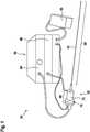
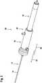
1 eine schematische Darstellung eines Lithotripsiesystems mit einer Lithotripsievorrichtung in einer perspektivischen Ansicht,2 eine schematische Darstellung eines Teils der Lithotripsievorrichtung in einer perspektivischen Ansicht,3 eine schematische Darstellung eines Teils der Lithotripsievorrichtung in einer Schnittansicht,4 eine schematische Darstellung eines Teils der Lithotripsievorrichtung mit einer Koppeleinheit in einer Schnittansicht,5 einen schematischen Ablaufplan eines beispielhaften Verfahrens zum Betrieb der Lithotripsievorrichtung und6 eine schematische Darstellung einer alternativen Ausgestaltung einer Lithotripsievorrichtung mit einer alternativen Lithotripsievorrichtung.
1 a schematic representation of a lithotripsy system with a lithotripsy device in a perspective view,2 a schematic representation of a part of the lithotripsy device in a perspective view,3 a schematic representation of a part of the lithotripsy device in a sectional view,4 a schematic representation of a part of the lithotripsy device with a coupling unit in a sectional view,5 a schematic flow chart of an exemplary method for operating the lithotripsy device and6 a schematic representation of an alternative embodiment of a lithotripsy device with an alternative lithotripsy device.
Beschreibung der AusführungsbeispieleDescription of the exemplary embodiments
Der Lithotripter 52 weist wenigstens eine Lithotripsievorrichtung auf. Im vorliegenden Fall bildet die Lithotripsievorrichtung den Lithotripter 52 vollständig aus. Alternativ könnte die Lithotripsievorrichtung nur einen Teil eines Lithotripters ausbilden.The
Das Lithotripsiesystem 54 weist wenigstens ein Steuergerät 56 auf. Das Steuergerät 56 ist zumindest zu einer Steuerung der Lithotripsievorrichtung eingerichtet. Die Lithotripsievorrichtung ist mit dem Steuergerät 56 verbunden. Das Steuergerät 56 besitzt zumindest eine Steuerelektronik (nicht dargestellt). Zu einer Ansteuerung der Lithotripsievorrichtung ist die Steuerelektronik elektrisch und/oder elektronisch mit dieser verbunden. Die Steuerelektronik enthält zumindest einen Prozessor. Ferner enthält die Steuerelektronik wenigstens einen Speicher. Auf dem Speicher ist ein Betriebsprogramm hinterlegt. Das Betriebsprogramm ist von dem Prozessor ausführbar.The
Das Lithotripsiesystem 54 weist wenigstens ein Betätigungsmittel 58 auf. Das Betätigungsmittel 58 ist zu einer Aktivierung und/oder Deaktivierung der Lithotripsievorrichtung ausgebildet. Das Betätigungsmittel 58 ist mit dem Steuergerät 56 und zwar insbesondere mit der Steuerelektronik des Steuergeräts 56 verbunden. Im vorliegenden Fall ist das Betätigungsmittel 58 als ein Fußschalter ausgebildet. Alternativ könnte ein Betätigungsmittel auch als ein anderer elektrischer und/oder elektronischer Schalter ausgebildet sein, wie beispielsweise als ein Druckknopf, einen Kippschalter oder dergleichen, welcher insbesondere Teil einer Lithotripsievorrichtung sein könnte. Auch könnte eine Bedienung der Lithotripsievorrichtung über ein externes Gerät, insbesondere ein Handgerät, wie beispielsweise ein Tablet, ein Smartphone, eine Smartwatch oder dergleichen erfolgen.The
Das Lithotripsiesystem 54 weist ferner eine Fördereinrichtung 60 auf. Die Fördereinrichtung 60 ist im vorliegenden Fall als eine Pumpe ausgebildet. Die Fördereinrichtung 60 ist zur Förderung eines Irrigats eingerichtet. Dazu ist die Fördereinrichtung 60 fluidtechnisch mit der Lithotripsievorrichtung verbunden. Die Fördereinrichtung 60 dient zum Absaugen eines Irrigats und/oder zu einem Freispulen mittels eines Irrigats bei einem Lithotripsievorgang. Bei dem Irrigat kann es sich um eine Flüssigkeit handeln, wie in etwa eine Kochsalzlösung. Beispielsweise können mit dem Irrigat Bruchteile eines bei einem Lithotripsievorgang zerstörten Konkrements abtransportiert werden.The
Zur Erzeugung von Stoßimpulsen, wie beispielsweise mittels eines Projektils 62, der Lithotripsievorrichtung ist wenigstens eine Antriebseinrichtung 64 vorgesehen (vgl.
Die Lithotripsievorrichtung besitzt einen proximalen Abschnitt 66. Der proximale Abschnitt 66 ist bei einer Bedienung einem Bediener der Lithotripsievorrichtung zugewandt. Der proximale Abschnitt 66 ist bei einer Bedienung einem Patienten abgewandt. Der proximale Abschnitt 66 liegt bei einer Behandlung eines Patienten außerhalb des Patienten. Ferner besitzt die Lithotripsievorrichtung einen distalen Abschnitt 68. Der distale Abschnitt 68 ist bei einer Bedienung einem Bediener der Lithotripsievorrichtung abgewandt. Der distale Abschnitt 68 ist bei einer Bedienung einem Patienten zugewandt. Der distale Abschnitt 68 liegt bei einer Behandlung eines Patienten zumindest teilweise innerhalb des Patienten.The lithotripsy device has a
Die Lithotripsievorrichtung weist ein Gehäuse 70 auf. Das Gehäuse 70 ist hohlzylinderförmig. Das Gehäuse 70 bildet zumindest teilweise den proximalen Abschnitt 66 der Lithotripsievorrichtung aus. Das Gehäuse 70 dient zur Anordnung weiterer Komponenten der Lithotripsievorrichtung.The lithotripsy device has a
Ferner weist die Lithotripsievorrichtung eine Handhabe 72 auf. Die Handhabe 72 ist zu einer manuellen Bedienung der Lithotripsievorrichtung ausgebildet. Die Handhabe 72 ist von dem Gehäuse 70 ausgebildet. Die Handhabe 72 bildet zumindest teilweise den proximalen Abschnitt 66a aus. Alternativ könnte insbesondere bei einer robotischen Ansteuerung einer solchen Lithotripsievorrichtung auch auf eine Handhabe verzichtet werden oder zu einer Anbindung an einen Roboterarm genutzt werden.The lithotripsy device also has a
Die Lithotripsievorrichtung weist wenigstens einen Ultraschallgenerator 74 auf. Der Ultraschallgenerator 74 ist dazu ausgebildet, Ultraschallwellen bereitzustellen. Zu einer Ansteuerung ist der Ultraschallgenerator 74 mit dem Steuergerät 56 und zwar insbesondere der Steuerelektronik verbunden. Der Ultraschallgenerator 74 ist zumindest teilweise in dem Gehäuse 70 angeordnet. Im vorliegenden Fall ist der Ultraschallgenerator 74 vollständig in dem Gehäuse 70 angeordnet. Der Ultraschallgenerator 74 bildet zumindest teilweise den proximalen Abschnitt 66 der Lithotripsievorrichtung aus.The lithotripsy device has at least one
Der Ultraschallgenerator 74 enthält wenigstens einen Ultraschallaktor 76. Im vorliegenden Fall weist der Ultraschallgenerator 74 mehrere Ultraschallaktoren 76 auf. Der Ultraschallgenerator 74 weist zwei Ultraschallaktoren 76 auf. Die Ultraschallaktoren 76 sind aneinander anliegend gestapelt angeordnet. Der Übersichtlichkeit halber ist in den Zeichnungen nur ein Ultraschallaktor 76 mit einem Bezugszeichen versehen. Die Ultraschallaktoren 76 sind zumindest im Wesentlichen identisch zueinander ausgebildet. Im Folgenden ist nur ein Ultraschallaktor 76 näher beschrieben. Diese Beschreibung ist auch auf die weiteren Ultraschallaktoren 76 übertragbar. Im vorliegenden Fall ist der Ultraschallaktor 76 als ein Piezoaktor ausgebildet. Der Ultraschallaktor 76 ist zylinderplattenförmig ausgebildet. Der Übersichtlichkeit halber sind etwaige Anschluss- und/oder Kontaktierungsmittel und/oder Isolationen der Ultraschallaktoren 76 nicht in der
Ferner weist die Lithotripsievorrichtung wenigstens ein Ultraschallhorn 18 auf. Das Ultraschallhorn 18 nimmt die von dem Ultraschallgenerator 74 bereitgestellten Ultraschallwellen auf. Das Ultraschallhorn 18 ist zur Übertragung von Ultraschallwellen ausgebildet. Das Ultraschallhorn 18 liegt an dem Ultraschallaktor 76 an.Furthermore, the lithotripsy device has at least one
Das Ultraschallhorn 18 ist zumindest teilweise in dem Gehäuse 70 angeordnet. Das Ultraschallhorn 18 bildet zumindest teilweise den proximalen Abschnitt 66 der Lithotripsievorrichtung aus. Das Ultraschallhorn 18 ist zumindest teilweise außerhalb des Gehäuse 70 angeordnet. Das Ultraschallhorn 18 weist die Form eines Rotationskörpers auf. Im vorliegenden Fall weist das Ultraschallhorn 18 eine hohlzylinderartige Form auf. Das Ultraschallhorn 18 ist zumindest teilweise aus Metall, insbesondere Stahl oder Titan ausgebildet. Der Ultraschallgenerator 74 liegt an dem Ultraschallhorn 18 an.The
Das Ultraschallhorn 18 verjüngt sich entlang der ersten Übertragungsrichtung 20. Das Ultraschallhorn 18 weist eine Verjüngung auf. Die Verjüngung liegt innerhalb des Gehäuses 70. Die Verjüngung ist frei von Stufen. Die Verjüngung weist einen stetigen Verlauf auf. Der Verlauf der Verjüngung ist konkav. Der Verlauf der Verjüngung ist exponentiell. Alternativ oder zusätzlich könnte die Verjüngung auch stufenförmig oder katenoidalförmig sein. Das Ultraschallhorn 18 weist eine Ausnehmung 80 auf. Die Ausnehmung 80 verläuft koaxial entlang einer Rotationsachse des Ultraschallhorns 18.The
Die Lithotripsievorrichtung weist wenigstens eine Sonotrode 10 auf. Die Sonotrode 10 weist eine Haupterstreckung 26 auf. Die Sonotrode 10 ist zumindest teilweise außerhalb des Gehäuse 70 angeordnet. Die Sonotrode 10 bildet zumindest zu einem Großteil den distalen Abschnitt 68 der Lithotripsievorrichtung aus. Die Sonotrode 10 ist rohrförmig ausgebildet. Die Sonotrode 10 ist starr ausgebildet. Die Sonotrode 10 besteht zumindest teilweise aus Metall, insbesondere Stahl. Zur Aufnahme von Ultraschallwellen weist die Sonotrode 10 wenigstens einen Sonotrodenkopf 12 auf. Der Sonotrodenkopf 12 bildet zumindest teilweise ein proximales End der Sonotrode 10 aus. Zur Beaufschlagung von Konkrementen weist die Sonotrode 10 wenigstens eine Sonotrodenspitze 14 auf. Die Sonotrodenspitze 14 bildet zumindest teilweise ein distales Ende der Sonotrode 10 aus. Die Sonotrodenspitze 14 ist mit dem Sonotrodenkopf 12 verbunden.The lithotripsy device has at least one
Die Sonotrode 10 ist zumindest teilweise in/an dem Ultraschallhorn 18 angeordnet. Die Sonotrode 10 ist von dem Ultraschallhorn 18 umgeben. Das Ultraschallhorn 18 ist die Sonotrode 10 koaxial umgebend angeordnet. Die Sonotrode 10 ist in der Ausnehmung 80 des Ultraschallhorns 18 angeordnet. Die Sonotrode 10 weist eine Haupterstreckung 26 auf. Das Ultraschallhorn 18 weist eine Haupterstreckung 28 auf. Die Haupterstreckung 26 der Sonotrode 10 ist größer als die Haupterstreckung 28 des Ultraschallhorns 18. Die Sonotrode 10 und die Ultraschallaktoren 76 sind so zueinander angeordnet, dass die Haupterstreckung 28 des Ultraschallhorn 18 vollständig innerhalb der Haupterstreckung 26 der Sonotrode 10 liegt.The
Das Ultraschallhorn 18 ist dazu eingerichtet, entlang einer ersten Übertragungsrichtung 20 Ultraschallwellen zumindest mittelbar auf einen Sonotrodenkopf 12 der Sonotrode 10 zu übertragen und zu fokussieren. Die erste Übertragungsrichtung 20 entspricht einer proximalen Richtung. Die Sonotrode 10a ist mit dem Ultraschallhorn 18 verbunden. Der Sonotrodenkopf 12 ist mit dem Ultraschallhorn 18 verbunden. Die Sonotrode 10 und das Ultraschallhorn 18 sind im vorliegenden Fall miteinander verschraubt. Alternativ oder zusätzlich kann die Sonotrode mit dem Ultraschallhorn verklebt oder verlötet sein. Ferner ist denkbar, dass eine solche Sonotrode mit solch einem Ultraschallhorn einstückig ausgebildet sein könnte.The
Die Sonotrode 10 ist dazu eingerichtet, entlang wenigstens einer zweiten Übertragungsrichtung 22, die von der ersten Übertragungsrichtung 20 verschieden ist, die Ultraschallwellen vom Sonotrodenkopf 12 zur Sonotrodenspitze 14 zu übertragen. Die zweite Übertragungsrichtung 22 entspricht einer distalen Richtung. Die erste Übertragungsrichtung 20 und die zweite Übertragungsrichtung 22 sind einander entgegengerichtet. Die Sonotrode 10 durchstößt das Ultraschallhorn 18 entlang der zweiten Übertragungsrichtung 22. Die Sonotrode 10 ragt proximalseitig aus dem Ultraschallhorn 18 heraus. Ferner ragt sie Sonotrode 10 distalseitig aus den Ultraschallwellen heraus.The
Zusätzlich zu einer Behandlung mit Ultraschallwellen ist die Lithotripsievorrichtung dazu eingerichtet, Stoßimpulse auf Konkremente zu übertragen. Dazu weist die Lithotripsievorrichtung eine Stoßimpulseinheit 32 auf. Die Stoßimpulseinheit 32 wenigstens ein Projektil 62 auf. Das Projektil 62 ist linear beweglich gelagert. In wenigstens einem Betriebszustand ist das Projektil 62 dazu ausgebildet, die Sonotrode 10 und/oder das Ultraschallhorn 18 zumindest mittelbar zu beaufschlagen. Im vorliegenden Fall beaufschlagt das Projektil 62 die Sonotrode 10 mittelbar. Zur Lagerung des Projektils 62 weist die Stoßimpulseinheit 32 wenigstens einen Führungskanal 82 auf. Die Lithotripsievorrichtung weist ein Führungsrohr 84 auf, welches den Führungskanal 82 begrenzt. Alternativ ist es denkbar, dass das Projektil innerhalb der Sonotrode oder des Ultraschallhorns beweglich gelagert sein könnte.In addition to treatment with ultrasonic waves, the lithotripsy device is set up to transmit impact pulses to calculi. For this purpose, the lithotripsy device has a
Die Antriebseinrichtung 64 ist mit der Stoßimpulseinheit 32 gekoppelt. Die die Stoßimpulseinheit 32 ist mit dem Führungskanal 82 verbunden. An dem Führungsrohr 84 ist ein Verbindungsstutzen angeordnet. Die Antriebseinrichtung 64a ist über einen Schlauch mit dem Verbindungsstutzen verbunden. Die Antriebseinrichtung 64a überträgt Druckluftstöße auf den Führungskanal 82, wodurch das in dem Führungskanal 82 angeordnete Projektil 62a beschleunigt wird. Die Antriebseinrichtung 64a beschleunigt das Projektil 62a innerhalb des Führungskanals 82.The
Die Lithotripsievorrichtung weist eine Koppeleinheit 30 auf (siehe
Die Koppeleinheit 30 weist einen Schnellverbinder 40 auf. Der Schnellverbinder 40 ist zu einer herstell- und lösbaren mechanischen Verbindung der Stoßimpulseinheit 32 mit der Sonotrode 10 eingerichtet. Der Schnellverbinder 40 ist dazu eingerichtet, eine werkzeuglos und zerstörungsfrei lösbare Verbindung herzustellen. Im vorliegenden Fall ist die Verbindung eine kraft- und/oder formschlüssige Verbindung. Der Schnellverbinder 40 bildet im vorliegenden Fall den Schraubverschluss aus. Alternativ sind noch andere Schnellverbinderarten denkbar, wie beispielsweise einen Bajonettverschluss oder dergleichen.The
Die Lithotripsievorrichtung weist eine Fluideinheit 42 auf. Die Fluideinheit 42 ist dazu eingerichtet, ein Fluid zum Spülen bereitzustellen und/oder ein Fluid abzuführen. Die Fluideinheit 42 weist wenigstens einen Fluidkanal 44 auf. Der Fluidkanal 44 ist zumindest teilweise von der Sonotrode 10 ausgebildet. Die Sonotrode 10 als eine axiale Ausnehmung auf, welche den Fluidkanal 44 teilweise ausbildet. Der Fluidkanal 44 ist zumindest teilweise von der Koppeleinheit 30 ausgebildet. Das Übertragungselement 34 weist eine axiale Ausnehmung auf, welche den Fluidkanal 44 teilweise ausbildet.The lithotripsy device has a
Der Fluidkanal 44 weist wenigstens eine Abwinklung 46 auf. Die Abwinklung 46 des Fluidkanals 44 ist im Bereich der Koppeleinheit 30 angeordnet. Die Abwinklung 46 ist in das Übertragungselement 34 integriert. Das Übertragungselement 34 weist wenigstens eine radiale Öffnung auf. Die radiale Öffnung stellt eine Verbindung zu der axialen Ausnehmung des Übertragungselements 34 her.The
Die Lithotripsievorrichtung weist wenigstens eine Lagereinheit 48 auf. Die Lagereinheit 48 ist dazu eingerichtet, die Sonotrode 10 beweglich entlang der ersten und/oder zweiten Übertragungsrichtung 20, 22 schwimmend zu lagern. Die Lagereinheit 48 ist als ein Gleitlager ausgebildet. Die Lagereinheit 48 weist zumindest ein Dichtelement 50 auf. Die Lagereinheit 48 ist von aneinander liegenden Oberflächen der Sonotrode 10 und/oder das Übertragungselement 34 sowie eines in das Gehäuse 70 eingelassenen Führungskanal 82 gebildet.The lithotripsy device has at least one
Das Verfahren umfasst einen Verfahrensschritt 100. In dem Verfahrensschritt 100 wird der Ultraschallgenerator 74 aktiviert. Der Ultraschallgenerator 74 erzeugt Ultraschallwellen. Die Ultraschallwellen werden von dem Ultraschallhorn 18 entlang der ersten Übertragungsrichtung 20 übertragen und fokussiert. Die Ultraschallwellen werden von dem Sonotrodenkopf 12 aufgenommen. Von dem Sonotrodenkopf 12 aus werden die Ultraschallwellen entlang einer zweiten Übertragungsrichtung 22 auf den Sonotrodenspitze 14 übertragen. Die Sonotrodenspitze 14 überträgt die Ultraschallwellen wiederum auf etwaige Konkremente, welche hierdurch zerstört werden können.The method includes a method step 100. In method step 100, the
Das Verfahren umfasst ein Verfahrensschritt 102. In dem Verfahrensschritt 102 wird die Stoßimpulseinheit 32 aktiviert. Die Antriebseinrichtung 64 beschleunigt das Projektil 62 pneumatisch. Das Projektil 62 schlägt am Ende einer Beschleunigungsstrecke auf das Übertragungselement 34. Dadurch wird eine Bewegung des Projektils 62 größtenteils gestoppt und ein Stoßimpuls des Projektils 62 an das Übertragungselement 34 abgegeben. Da das Übertragungselement 34 in Kontakt mit der Sonotrode 10 steht, überträgt diese wiederum den Stoßimpuls an den Sonotrodenkopf 12. Der Stoßimpuls wird entlang der zweiten Übertragungsrichtung 22 von dem Sonotrodenkopf 12 auf die Sonotrodenspitze 14 übertragen. Die Sonotrodenspitze 14 überträgt den Stoßimpuls wiederum auf etwaige Konkremente, welche hierdurch zerstört werden können.The method includes a
Die Verfahrensschritte 100, 102 können dabei in beliebiger Reihenfolge alternierend oder aber auch gleichzeitig durchgeführt werden. Gerade bei der gleichzeitigen Ausführung der Verfahrensschritte 100 und 102 kann ein Kombinationsbetrieb erzielt werden, bei welchen etwaige Konkrementen gleichzeitig mit Ultraschallwellen und Stoßimpulsen beaufschlagt werden können.The method steps 100, 102 can be carried out alternately in any order or simultaneously. It is precisely when method steps 100 and 102 are carried out simultaneously that a combined operation can be achieved, in which any concretions can be subjected to ultrasonic waves and impact pulses at the same time.
In der
Die Lithotripsievorrichtung weist wenigstens eine Lagereinheit 48a auf. Die Lagereinheit 48a ist dazu eingerichtet, eine Sonotrode 10a der Lithotripsievorrichtung beweglich entlang einer ersten und/oder einer zweiten Übertragungsrichtung 20a, 22a schwimmend zu lagern. Die Lagereinheit 48a weist zumindest ein Dichtelement 50a auf, welches wenigstens teilweise einen Fluidkanal 44a einer Fluideinheit 42a der Lithotripsievorrichtung begrenzt. Das Dichtelement 50a ist mit der Sonotrode 10a und einem Übertragungselement 34a einer Koppeleinheit 30a der Lithotripsievorrichtung verbunden. Das Dichtelement 50a ist als ein Faltenbalg ausgebildet ist. Dichtelement 50a ist kraft- und/oder formschlüssig mit einer Sonotrode 10a und dem Übertragungselement 34a verbunden.
- 10
- Sonotrode
- 12
- Sonotrodenkopf
- 14
- Sonotrodenspitze
- 16
- Ultraschalleinheit
- 18
- Ultraschallhorn
- 20
- erste Übertragungsrichtung
- 22
- zweite Übertragungsrichtung
- 26
- Haupterstreckung der Sonotrode
- 28
- Haupterstreckung des Ultraschallhorns
- 30
- Koppeleinheit
- 32
- Stoßimpulseinheit
- 34
- Übertragungselement
- 36
- Erste Wirkfläche
- 38
- Zweite Wirkfläche
- 40
- Schnellverbinder
- 42
- Fluideinheit
- 44
- Fluidkanal
- 46
- Abwinklung
- 48
- Lagereinheit
- 50
- Dichtelement
- 52
- Lithotripter
- 54
- Lithotripsiesystem
- 56
- Steuergerät
- 58
- Betätigungsmittel
- 60
- Fördereinrichtung
- 62
- Projektil
- 64
- Antriebseinrichtung
- 66
- Proximaler Abschnitt
- 68
- Distaler Abschnitt
- 70
- Gehäuse
- 72
- Handhabe
- 74
- Ultraschallgenerator
- 76
- Ultraschallaktor
- 80
- Ausnehmung des Ultraschallhorns
- 82
- Führungskanal
- 84
- Führungsrohr
- 100
- Verfahrensschritt
- 102
- Verfahrensschritt
- 10
- sonotrode
- 12
- sonotrode head
- 14
- sonotrode tip
- 16
- ultrasonic unit
- 18
- ultrasonic horn
- 20
- first transmission direction
- 22
- second transmission direction
- 26
- Main extension of the sonotrode
- 28
- Main extension of the ultrasonic horn
- 30
- coupling unit
- 32
- shock impulse unit
- 34
- transmission element
- 36
- First active surface
- 38
- Second effective area
- 40
- quick connector
- 42
- fluid unit
- 44
- fluid channel
- 46
- deflection
- 48
- storage unit
- 50
- sealing element
- 52
- lithotripter
- 54
- lithotripsy system
- 56
- control unit
- 58
- actuating means
- 60
- conveyor
- 62
- projectile
- 64
- drive device
- 66
- Proximal Section
- 68
- distal section
- 70
- casing
- 72
- handle
- 74
- ultrasonic generator
- 76
- ultrasonic actuator
- 80
- Recess of the ultrasonic horn
- 82
- guide channel
- 84
- guide tube
- 100
- process step
- 102
- process step
Claims (20)
Translated fromGermanPriority Applications (3)
| Application Number | Priority Date | Filing Date | Title |
|---|---|---|---|
| DE102020117713.5ADE102020117713B4 (en) | 2020-07-06 | 2020-07-06 | Lithotripsy device and method for operating a lithotripsy device |
| PCT/EP2021/068510WO2022008440A1 (en) | 2020-07-06 | 2021-07-05 | Lithotripsy device, and method for operating a lithotripsy device |
| EP21746651.5AEP4175567B1 (en) | 2020-07-06 | 2021-07-05 | Lithotripsy device, and method for test operating a lithotripsy device |
Applications Claiming Priority (1)
| Application Number | Priority Date | Filing Date | Title |
|---|---|---|---|
| DE102020117713.5ADE102020117713B4 (en) | 2020-07-06 | 2020-07-06 | Lithotripsy device and method for operating a lithotripsy device |
Publications (2)
| Publication Number | Publication Date |
|---|---|
| DE102020117713A1true DE102020117713A1 (en) | 2022-01-13 |
| DE102020117713B4 DE102020117713B4 (en) | 2024-11-07 |
Family
ID=77104014
Family Applications (1)
| Application Number | Title | Priority Date | Filing Date |
|---|---|---|---|
| DE102020117713.5AActiveDE102020117713B4 (en) | 2020-07-06 | 2020-07-06 | Lithotripsy device and method for operating a lithotripsy device |
Country Status (3)
| Country | Link |
|---|---|
| EP (1) | EP4175567B1 (en) |
| DE (1) | DE102020117713B4 (en) |
| WO (1) | WO2022008440A1 (en) |
Cited By (23)
| Publication number | Priority date | Publication date | Assignee | Title |
|---|---|---|---|---|
| US11517713B2 (en) | 2019-06-26 | 2022-12-06 | Boston Scientific Scimed, Inc. | Light guide protection structures for plasma system to disrupt vascular lesions |
| US11583339B2 (en) | 2019-10-31 | 2023-02-21 | Bolt Medical, Inc. | Asymmetrical balloon for intravascular lithotripsy device and method |
| US11648057B2 (en) | 2021-05-10 | 2023-05-16 | Bolt Medical, Inc. | Optical analyzer assembly with safety shutdown system for intravascular lithotripsy device |
| US11660427B2 (en) | 2019-06-24 | 2023-05-30 | Boston Scientific Scimed, Inc. | Superheating system for inertial impulse generation to disrupt vascular lesions |
| DE102021131670A1 (en) | 2021-12-01 | 2023-06-01 | Karl Storz Se & Co. Kg | Lithotripsy device for crushing bodily stones and method for adjusting an acceleration distance of an acceleration tube of a lithotripsy device |
| US11672585B2 (en) | 2021-01-12 | 2023-06-13 | Bolt Medical, Inc. | Balloon assembly for valvuloplasty catheter system |
| US11672599B2 (en) | 2020-03-09 | 2023-06-13 | Bolt Medical, Inc. | Acoustic performance monitoring system and method within intravascular lithotripsy device |
| US11707323B2 (en) | 2020-04-03 | 2023-07-25 | Bolt Medical, Inc. | Electrical analyzer assembly for intravascular lithotripsy device |
| US11717139B2 (en) | 2019-06-19 | 2023-08-08 | Bolt Medical, Inc. | Plasma creation via nonaqueous optical breakdown of laser pulse energy for breakup of vascular calcium |
| US11806075B2 (en) | 2021-06-07 | 2023-11-07 | Bolt Medical, Inc. | Active alignment system and method for laser optical coupling |
| US11819229B2 (en) | 2019-06-19 | 2023-11-21 | Boston Scientific Scimed, Inc. | Balloon surface photoacoustic pressure wave generation to disrupt vascular lesions |
| US11839391B2 (en) | 2021-12-14 | 2023-12-12 | Bolt Medical, Inc. | Optical emitter housing assembly for intravascular lithotripsy device |
| US11903642B2 (en) | 2020-03-18 | 2024-02-20 | Bolt Medical, Inc. | Optical analyzer assembly and method for intravascular lithotripsy device |
| EP4353162A1 (en)* | 2022-10-14 | 2024-04-17 | Karl Storz SE & Co. KG | Medical instrument for treating a body having a pressure relief device |
| DE102022109138B4 (en) | 2022-04-13 | 2024-06-20 | Karl Storz Se & Co. Kg | Lithotripsy device for breaking up body stones with a control sleeve and method for accelerating a projectile of a lithotripsy device |
| DE102022109140B4 (en) | 2022-04-13 | 2024-06-20 | Karl Storz Se & Co. Kg | Lithotripsy device for breaking up body stones with an axially movable acceleration tube and method for accelerating a projectile of a lithotripsy device |
| US12016610B2 (en) | 2020-12-11 | 2024-06-25 | Bolt Medical, Inc. | Catheter system for valvuloplasty procedure |
| US12102384B2 (en) | 2019-11-13 | 2024-10-01 | Bolt Medical, Inc. | Dynamic intravascular lithotripsy device with movable energy guide |
| US12207870B2 (en) | 2020-06-15 | 2025-01-28 | Boston Scientific Scimed, Inc. | Spectroscopic tissue identification for balloon intravascular lithotripsy guidance |
| US12274497B2 (en) | 2019-12-18 | 2025-04-15 | Bolt Medical, Inc. | Multiplexer for laser-driven intravascular lithotripsy device |
| US12274485B2 (en) | 2021-01-12 | 2025-04-15 | Bolt Medical, Inc. | Balloon assembly for valvuloplasty catheter system |
| US12295654B2 (en) | 2020-06-03 | 2025-05-13 | Boston Scientific Scimed, Inc. | System and method for maintaining balloon integrity within intravascular lithotripsy device with plasma generator |
| US12402946B2 (en) | 2019-06-19 | 2025-09-02 | Boston Scientific Scimed, Inc. | Breakdown of laser pulse energy for breakup of vascular calcium |
Families Citing this family (1)
| Publication number | Priority date | Publication date | Assignee | Title |
|---|---|---|---|---|
| DE102022129228A1 (en)* | 2022-11-04 | 2024-05-08 | Karl Storz Se & Co. Kg | Lithotripsy device for breaking up body stones with a lever element and retrofit kit for retrofitting an existing lithotripsy device |
Citations (2)
| Publication number | Priority date | Publication date | Assignee | Title |
|---|---|---|---|---|
| EP1163883A1 (en) | 2000-06-15 | 2001-12-19 | Ferton Holding SA | Intracorporeal lithotripter for removing calculi |
| US6875220B2 (en) | 2002-12-30 | 2005-04-05 | Cybersonics, Inc. | Dual probe |
Family Cites Families (18)
| Publication number | Priority date | Publication date | Assignee | Title |
|---|---|---|---|---|
| US3776560A (en) | 1971-03-04 | 1973-12-04 | Borg Warner | Bellows type fluid seal |
| JPS62127041A (en) | 1985-11-28 | 1987-06-09 | オリンパス光学工業株式会社 | Ultrasonic stone crushing probe |
| DE3707403C2 (en) | 1986-03-11 | 1996-08-01 | Olympus Optical Co | Medical resection device |
| DE4042435C3 (en) | 1990-02-02 | 1998-12-10 | Olympus Optical Co | Ultrasound treatment device |
| DE19507478C1 (en) | 1995-03-03 | 1996-05-15 | Siemens Ag | Therapy device for treatment with focused ultrasound |
| US6241703B1 (en) | 1996-08-19 | 2001-06-05 | Angiosonics Inc. | Ultrasound transmission apparatus having a tip |
| DE10021529A1 (en) | 2000-05-03 | 2001-11-15 | Celon Ag Medical Instruments | Manually operated ultrasonic breaker for crushing or removing human or animal tissue |
| DE10029582A1 (en) | 2000-06-15 | 2002-01-03 | Ferton Holding Sa | Device for removing body stones using an intracorporeal lithotripter |
| DE20022925U1 (en) | 2000-06-15 | 2002-10-02 | Ferton Holding S.A., Delemont | Body stone removal device using an intracorporeal lithotripter |
| DE10029580C1 (en) | 2000-06-15 | 2002-01-10 | Ferton Holding Sa | Device for removing body stones with an intracorporeal lithotripter |
| JP2004180997A (en) | 2002-12-04 | 2004-07-02 | Olympus Corp | Stone crushing apparatus under the use of endoscope |
| CN104519815B (en) | 2012-10-25 | 2017-04-12 | 奥林巴斯株式会社 | Ultrasonic probe |
| DE102014202571A1 (en) | 2014-02-12 | 2015-08-13 | Robert Bosch Gmbh | Pump for conveying a fluid |
| CN106102623B (en) | 2014-07-02 | 2018-09-28 | 奥林巴斯株式会社 | Ultrasonic probe and ultrasonic operation system |
| JP2018042185A (en) | 2016-09-09 | 2018-03-15 | マイクロソニック株式会社 | Ultrasonic wave transmission line and ultrasonic wave utilization device |
| DE102018101221B4 (en) | 2018-01-19 | 2023-05-17 | Ferton Holding S.A. | System for crushing and/or removing bodily stones and method of providing such a system |
| DE102018101215B4 (en) | 2018-01-19 | 2023-09-07 | Ferton Holding S.A. | Device for breaking up a body stone |
| US11918245B2 (en) | 2018-10-05 | 2024-03-05 | Kogent Surgical, LLC | Ultrasonic surgical handpiece with torsional transducer |
- 2020
- 2020-07-06DEDE102020117713.5Apatent/DE102020117713B4/enactiveActive
- 2021
- 2021-07-05EPEP21746651.5Apatent/EP4175567B1/enactiveActive
- 2021-07-05WOPCT/EP2021/068510patent/WO2022008440A1/ennot_activeCeased
Patent Citations (2)
| Publication number | Priority date | Publication date | Assignee | Title |
|---|---|---|---|---|
| EP1163883A1 (en) | 2000-06-15 | 2001-12-19 | Ferton Holding SA | Intracorporeal lithotripter for removing calculi |
| US6875220B2 (en) | 2002-12-30 | 2005-04-05 | Cybersonics, Inc. | Dual probe |
Cited By (28)
| Publication number | Priority date | Publication date | Assignee | Title |
|---|---|---|---|---|
| US11819229B2 (en) | 2019-06-19 | 2023-11-21 | Boston Scientific Scimed, Inc. | Balloon surface photoacoustic pressure wave generation to disrupt vascular lesions |
| US12402946B2 (en) | 2019-06-19 | 2025-09-02 | Boston Scientific Scimed, Inc. | Breakdown of laser pulse energy for breakup of vascular calcium |
| US11717139B2 (en) | 2019-06-19 | 2023-08-08 | Bolt Medical, Inc. | Plasma creation via nonaqueous optical breakdown of laser pulse energy for breakup of vascular calcium |
| US11660427B2 (en) | 2019-06-24 | 2023-05-30 | Boston Scientific Scimed, Inc. | Superheating system for inertial impulse generation to disrupt vascular lesions |
| US12311124B2 (en) | 2019-06-26 | 2025-05-27 | Boston Scientific Scimed, Inc. | Fortified balloon inflation fluid for plasma system to disrupt vascular lesions |
| US11517713B2 (en) | 2019-06-26 | 2022-12-06 | Boston Scientific Scimed, Inc. | Light guide protection structures for plasma system to disrupt vascular lesions |
| US12186499B2 (en) | 2019-06-26 | 2025-01-07 | Boston Scientific Scimed, Inc. | Light guide protection structures for plasma system to disrupt vascular lesions |
| US11911574B2 (en) | 2019-06-26 | 2024-02-27 | Boston Scientific Scimed, Inc. | Fortified balloon inflation fluid for plasma system to disrupt vascular lesions |
| US12280223B2 (en) | 2019-06-26 | 2025-04-22 | Boston Scientific Scimed, Inc. | Focusing element for plasma system to disrupt vascular lesions |
| US11583339B2 (en) | 2019-10-31 | 2023-02-21 | Bolt Medical, Inc. | Asymmetrical balloon for intravascular lithotripsy device and method |
| US12102384B2 (en) | 2019-11-13 | 2024-10-01 | Bolt Medical, Inc. | Dynamic intravascular lithotripsy device with movable energy guide |
| US12274497B2 (en) | 2019-12-18 | 2025-04-15 | Bolt Medical, Inc. | Multiplexer for laser-driven intravascular lithotripsy device |
| US11672599B2 (en) | 2020-03-09 | 2023-06-13 | Bolt Medical, Inc. | Acoustic performance monitoring system and method within intravascular lithotripsy device |
| US11903642B2 (en) | 2020-03-18 | 2024-02-20 | Bolt Medical, Inc. | Optical analyzer assembly and method for intravascular lithotripsy device |
| US11707323B2 (en) | 2020-04-03 | 2023-07-25 | Bolt Medical, Inc. | Electrical analyzer assembly for intravascular lithotripsy device |
| US12295654B2 (en) | 2020-06-03 | 2025-05-13 | Boston Scientific Scimed, Inc. | System and method for maintaining balloon integrity within intravascular lithotripsy device with plasma generator |
| US12207870B2 (en) | 2020-06-15 | 2025-01-28 | Boston Scientific Scimed, Inc. | Spectroscopic tissue identification for balloon intravascular lithotripsy guidance |
| US12016610B2 (en) | 2020-12-11 | 2024-06-25 | Bolt Medical, Inc. | Catheter system for valvuloplasty procedure |
| US12274485B2 (en) | 2021-01-12 | 2025-04-15 | Bolt Medical, Inc. | Balloon assembly for valvuloplasty catheter system |
| US11672585B2 (en) | 2021-01-12 | 2023-06-13 | Bolt Medical, Inc. | Balloon assembly for valvuloplasty catheter system |
| US11648057B2 (en) | 2021-05-10 | 2023-05-16 | Bolt Medical, Inc. | Optical analyzer assembly with safety shutdown system for intravascular lithotripsy device |
| US11806075B2 (en) | 2021-06-07 | 2023-11-07 | Bolt Medical, Inc. | Active alignment system and method for laser optical coupling |
| DE102021131670A1 (en) | 2021-12-01 | 2023-06-01 | Karl Storz Se & Co. Kg | Lithotripsy device for crushing bodily stones and method for adjusting an acceleration distance of an acceleration tube of a lithotripsy device |
| US12232753B2 (en) | 2021-12-14 | 2025-02-25 | Bolt Medical, Inc. | Optical emitter housing assembly for intravascular lithotripsy device |
| US11839391B2 (en) | 2021-12-14 | 2023-12-12 | Bolt Medical, Inc. | Optical emitter housing assembly for intravascular lithotripsy device |
| DE102022109140B4 (en) | 2022-04-13 | 2024-06-20 | Karl Storz Se & Co. Kg | Lithotripsy device for breaking up body stones with an axially movable acceleration tube and method for accelerating a projectile of a lithotripsy device |
| DE102022109138B4 (en) | 2022-04-13 | 2024-06-20 | Karl Storz Se & Co. Kg | Lithotripsy device for breaking up body stones with a control sleeve and method for accelerating a projectile of a lithotripsy device |
| EP4353162A1 (en)* | 2022-10-14 | 2024-04-17 | Karl Storz SE & Co. KG | Medical instrument for treating a body having a pressure relief device |
Also Published As
| Publication number | Publication date |
|---|---|
| EP4175567B1 (en) | 2025-04-02 |
| EP4175567A1 (en) | 2023-05-10 |
| DE102020117713B4 (en) | 2024-11-07 |
| WO2022008440A1 (en) | 2022-01-13 |
Similar Documents
| Publication | Publication Date | Title |
|---|---|---|
| DE102020117713B4 (en) | Lithotripsy device and method for operating a lithotripsy device | |
| EP2344252B1 (en) | Device for introducing shock waves into a living body and use thereof | |
| EP3733313B1 (en) | Lithotripsy device and test method for operating a lithotripsy device | |
| EP1163882A1 (en) | Intracorporeal lithotripter for removal of calculi | |
| DE19859135B4 (en) | Device for driving a wire pin, in particular a Kirschner wire, in bone material | |
| EP4267021A1 (en) | Lithotripsy device, lithotripsy system and method for operating a lithotripsy device | |
| DE102020105457B4 (en) | lithotripsy device | |
| DE3707403C2 (en) | Medical resection device | |
| EP4507594A1 (en) | Lithotripsy device for breaking up calculi with a control sleeve, and method for accelerating a projectile of a lithotripsy device | |
| DE19881185B4 (en) | Device for crushing concrements | |
| WO2023099466A1 (en) | Lithotripsy device for breaking up calculi and method for adjusting the acceleration path of an acceleration tube of a lithotripsy device | |
| DE102007013288B4 (en) | Apparatus for the treatment of biological body substances with mechanical pressure waves | |
| DE102009042276A1 (en) | Device for introducing shock wave into living body i.e. human body, in hand-held medical device for e.g. intracorporeal shock wave lithotripsy, has tensioning device allowing abrupt release of spring while delivering shock pulses | |
| DE3814743C2 (en) | Device for dissolving concrements in a body cavity | |
| DE602004007758T2 (en) | Instrument for the medical treatment of tissue by means of shock waves | |
| DE102022126988B3 (en) | Head device of a lithotripsy device, lithotripsy device and retrofit kit for retrofitting an existing lithotripsy device | |
| DE102021121986B3 (en) | lithotripsy device | |
| DE102022133521B3 (en) | Holding device for a lithotripsy device and lithotripsy device for breaking up body stones | |
| DE102022126994A1 (en) | Head assembly of a lithotripsy device, lithotripsy device for crushing body stones and retrofit kit | |
| DE102008051174A1 (en) | Device for introducing shock wave into living body i.e. human body, in hand-held medical device for e.g. intracorporeal shock wave lithotripsy, has tensioning device allowing abrupt release of spring while delivering shock pulses | |
| WO2024094842A1 (en) | Lithotripsy apparatus for breaking up calculi, having a lever element, and retrofit kit for retrofitting an existing lithotripsy apparatus | |
| DE102022126990A1 (en) | Hollow probe for a lithotripsy device, lithotripsy device for crushing body stones, retrofit kit and method for manufacturing a hollow probe | |
| DE102022109140A1 (en) | Lithotripsy device for breaking up body stones with an axially movable acceleration tube and method for accelerating a projectile of a lithotripsy device | |
| DE2053982B2 (en) | Ultrasonic disintegrator for calculi - has piezoelectric transducer coupled to cystoscope between different metal discs |
Legal Events
| Date | Code | Title | Description |
|---|---|---|---|
| R012 | Request for examination validly filed | ||
| R016 | Response to examination communication | ||
| R018 | Grant decision by examination section/examining division | ||
| R026 | Opposition filed against patent |