DE102020116263A1 - ARRANGEMENT FOR A VEHICLE, VEHICLE LAMP AND VEHICLE - Google Patents
ARRANGEMENT FOR A VEHICLE, VEHICLE LAMP AND VEHICLEDownload PDFInfo
- Publication number
- DE102020116263A1 DE102020116263A1DE102020116263.4ADE102020116263ADE102020116263A1DE 102020116263 A1DE102020116263 A1DE 102020116263A1DE 102020116263 ADE102020116263 ADE 102020116263ADE 102020116263 A1DE102020116263 A1DE 102020116263A1
- Authority
- DE
- Germany
- Prior art keywords
- light
- optical element
- coupling
- vehicle
- arrangement
- Prior art date
- Legal status (The legal status is an assumption and is not a legal conclusion. Google has not performed a legal analysis and makes no representation as to the accuracy of the status listed.)
- Pending
Links
- 230000003287optical effectEffects0.000claimsabstractdescription203
- 230000008878couplingEffects0.000claimsdescription89
- 238000010168coupling processMethods0.000claimsdescription89
- 238000005859coupling reactionMethods0.000claimsdescription89
- 239000000463materialSubstances0.000claimsdescription8
- 239000004922lacquerSubstances0.000claimsdescription5
- 230000002093peripheral effectEffects0.000claimsdescription5
- 239000004020conductorSubstances0.000claimsdescription3
- 238000001459lithographyMethods0.000claimsdescription2
- 230000006870functionEffects0.000description11
- 238000001746injection mouldingMethods0.000description9
- 238000009434installationMethods0.000description7
- 238000013461designMethods0.000description6
- 238000000605extractionMethods0.000description6
- 229920003023plasticPolymers0.000description5
- 230000007704transitionEffects0.000description5
- 238000011982device technologyMethods0.000description3
- 238000009826distributionMethods0.000description3
- 238000004519manufacturing processMethods0.000description3
- 239000002184metalSubstances0.000description3
- 230000003071parasitic effectEffects0.000description3
- 238000007740vapor depositionMethods0.000description3
- 230000008901benefitEffects0.000description2
- 239000003086colorantSubstances0.000description2
- 230000007423decreaseEffects0.000description2
- 229910052736halogenInorganic materials0.000description2
- 150000002367halogensChemical class0.000description2
- 238000003384imaging methodMethods0.000description2
- 238000000465mouldingMethods0.000description2
- 239000003973paintSubstances0.000description2
- 239000004417polycarbonateSubstances0.000description2
- 229920001296polysiloxanePolymers0.000description2
- 2380000101463D printingMethods0.000description1
- OAICVXFJPJFONN-UHFFFAOYSA-NPhosphorusChemical compound[P]OAICVXFJPJFONN-UHFFFAOYSA-N0.000description1
- 238000002679ablationMethods0.000description1
- 239000000654additiveSubstances0.000description1
- 230000000996additive effectEffects0.000description1
- 238000000149argon plasma sinteringMethods0.000description1
- 230000033228biological regulationEffects0.000description1
- 238000006243chemical reactionMethods0.000description1
- 239000011248coating agentSubstances0.000description1
- 238000000576coating methodMethods0.000description1
- 150000001875compoundsChemical class0.000description1
- 230000001419dependent effectEffects0.000description1
- 239000000975dyeSubstances0.000description1
- 238000005516engineering processMethods0.000description1
- 239000011888foilSubstances0.000description1
- 239000011521glassSubstances0.000description1
- 230000012447hatchingEffects0.000description1
- 238000002347injectionMethods0.000description1
- 239000007924injectionSubstances0.000description1
- 238000003780insertionMethods0.000description1
- 230000037431insertionEffects0.000description1
- 239000003550markerSubstances0.000description1
- 238000001465metallisationMethods0.000description1
- 238000000034methodMethods0.000description1
- 238000002156mixingMethods0.000description1
- 239000004033plasticSubstances0.000description1
- 229920000515polycarbonatePolymers0.000description1
- 238000012545processingMethods0.000description1
- 230000005855radiationEffects0.000description1
- 230000001105regulatory effectEffects0.000description1
- 230000009131signaling functionEffects0.000description1
- 239000011343solid materialSubstances0.000description1
- 239000000758substrateSubstances0.000description1
- 238000009827uniform distributionMethods0.000description1
- XLYOFNOQVPJJNP-UHFFFAOYSA-NwaterSubstancesOXLYOFNOQVPJJNP-UHFFFAOYSA-N0.000description1
Images


Classifications
- F—MECHANICAL ENGINEERING; LIGHTING; HEATING; WEAPONS; BLASTING
- F21—LIGHTING
- F21S—NON-PORTABLE LIGHTING DEVICES; SYSTEMS THEREOF; VEHICLE LIGHTING DEVICES SPECIALLY ADAPTED FOR VEHICLE EXTERIORS
- F21S43/00—Signalling devices specially adapted for vehicle exteriors, e.g. brake lamps, direction indicator lights or reversing lights
- F21S43/20—Signalling devices specially adapted for vehicle exteriors, e.g. brake lamps, direction indicator lights or reversing lights characterised by refractors, transparent cover plates, light guides or filters
- F21S43/235—Light guides
- F21S43/236—Light guides characterised by the shape of the light guide
- F21S43/239—Light guides characterised by the shape of the light guide plate-shaped
- F—MECHANICAL ENGINEERING; LIGHTING; HEATING; WEAPONS; BLASTING
- F21—LIGHTING
- F21S—NON-PORTABLE LIGHTING DEVICES; SYSTEMS THEREOF; VEHICLE LIGHTING DEVICES SPECIALLY ADAPTED FOR VEHICLE EXTERIORS
- F21S41/00—Illuminating devices specially adapted for vehicle exteriors, e.g. headlamps
- F21S41/20—Illuminating devices specially adapted for vehicle exteriors, e.g. headlamps characterised by refractors, transparent cover plates, light guides or filters
- F21S41/24—Light guides
- F—MECHANICAL ENGINEERING; LIGHTING; HEATING; WEAPONS; BLASTING
- F21—LIGHTING
- F21S—NON-PORTABLE LIGHTING DEVICES; SYSTEMS THEREOF; VEHICLE LIGHTING DEVICES SPECIALLY ADAPTED FOR VEHICLE EXTERIORS
- F21S43/00—Signalling devices specially adapted for vehicle exteriors, e.g. brake lamps, direction indicator lights or reversing lights
- F21S43/20—Signalling devices specially adapted for vehicle exteriors, e.g. brake lamps, direction indicator lights or reversing lights characterised by refractors, transparent cover plates, light guides or filters
- F21S43/235—Light guides
- F21S43/236—Light guides characterised by the shape of the light guide
- F21S43/241—Light guides characterised by the shape of the light guide of complex shape
- F—MECHANICAL ENGINEERING; LIGHTING; HEATING; WEAPONS; BLASTING
- F21—LIGHTING
- F21S—NON-PORTABLE LIGHTING DEVICES; SYSTEMS THEREOF; VEHICLE LIGHTING DEVICES SPECIALLY ADAPTED FOR VEHICLE EXTERIORS
- F21S43/00—Signalling devices specially adapted for vehicle exteriors, e.g. brake lamps, direction indicator lights or reversing lights
- F21S43/20—Signalling devices specially adapted for vehicle exteriors, e.g. brake lamps, direction indicator lights or reversing lights characterised by refractors, transparent cover plates, light guides or filters
- F21S43/235—Light guides
- F21S43/242—Light guides characterised by the emission area
- F21S43/245—Light guides characterised by the emission area emitting light from one or more of its major surfaces
- G—PHYSICS
- G02—OPTICS
- G02B—OPTICAL ELEMENTS, SYSTEMS OR APPARATUS
- G02B6/00—Light guides; Structural details of arrangements comprising light guides and other optical elements, e.g. couplings
- G02B6/0001—Light guides; Structural details of arrangements comprising light guides and other optical elements, e.g. couplings specially adapted for lighting devices or systems
- G02B6/0011—Light guides; Structural details of arrangements comprising light guides and other optical elements, e.g. couplings specially adapted for lighting devices or systems the light guides being planar or of plate-like form
- G02B6/0033—Means for improving the coupling-out of light from the light guide
- G02B6/0035—Means for improving the coupling-out of light from the light guide provided on the surface of the light guide or in the bulk of it
- G02B6/0045—Means for improving the coupling-out of light from the light guide provided on the surface of the light guide or in the bulk of it by shaping at least a portion of the light guide
- G—PHYSICS
- G02—OPTICS
- G02B—OPTICAL ELEMENTS, SYSTEMS OR APPARATUS
- G02B6/00—Light guides; Structural details of arrangements comprising light guides and other optical elements, e.g. couplings
- G02B6/0001—Light guides; Structural details of arrangements comprising light guides and other optical elements, e.g. couplings specially adapted for lighting devices or systems
- G02B6/0005—Light guides; Structural details of arrangements comprising light guides and other optical elements, e.g. couplings specially adapted for lighting devices or systems the light guides being of the fibre type
- G02B6/001—Light guides; Structural details of arrangements comprising light guides and other optical elements, e.g. couplings specially adapted for lighting devices or systems the light guides being of the fibre type the light being emitted along at least a portion of the lateral surface of the fibre
Landscapes
- Physics & Mathematics (AREA)
- Engineering & Computer Science (AREA)
- General Engineering & Computer Science (AREA)
- General Physics & Mathematics (AREA)
- Optics & Photonics (AREA)
- Lighting Device Outwards From Vehicle And Optical Signal (AREA)
- Non-Portable Lighting Devices Or Systems Thereof (AREA)
Abstract
Translated fromGermanDescription
Translated fromGermanDie Erfindung geht aus von einer Anordnung für ein Fahrzeug, einer Fahrzeugleuchte und einem Fahrzeug mit dieser Anordnung.The invention is based on an arrangement for a vehicle, a vehicle lamp and a vehicle with this arrangement.
Vermehrt kommen in der Automobilindustrie aktive Beleuchtungsszenarien zu designtechnischer Akzentsetzung ins Gespräch, beispielsweise um verschiedene Modelle oder Fabrikate voneinander abzugrenzen. Die Beleuchtungsszenarien kommen auch verstärkt außerhalb der Scheinwerfer, wie beispielsweise der Frontscheinwerfer oder Rückleuchten, vor. Neben einer designtechnischen Akzentsetzung liegt auch ein Augenmerk auf einer Darstellung verschiedenster Symbole zum Geben von Hinweisen oder zur Kommunikation mit anderen Verkehrsteilnehmern oder Personen, die am Straßenverkehr teilnehmen. Bei den Symbolen kann es sich zum Beispiel um Logos, insbesondere Logos von Herstellern, handeln, aber auch um technische Informationen, wie beispielsweise Batterieladezustandsanzeigen. Eine Integration der aktiven Beleuchtungsszenarien kann beispielsweise in einer Karosserie, einem Stoßfänger, einer Innenverkleidung oder einer Abdeckscheibe eines Fahrzeugs erfolgen.In the automotive industry, active lighting scenarios for design-related accents are increasingly being discussed, for example to differentiate between different models or makes. The lighting scenarios also occur increasingly outside the headlights, such as the front headlights or taillights. In addition to accentuating the design, attention is also paid to the representation of a wide variety of symbols for giving information or for communicating with other road users or people who take part in road traffic. The symbols can be, for example, logos, in particular logos of manufacturers, but also technical information such as battery charge status displays. The active lighting scenarios can be integrated, for example, in a body, a bumper, an interior trim or a cover pane of a vehicle.
Es ist eine Aufgabe der Erfindung, eine vorrichtungstechnisch einfache und kostengünstige Anordnung für ein Fahrzeug zu schaffen, durch die eine ästhetische Anmutung des Fahrzeugs verbessert ist. Eine weitere Aufgabe der Erfindung ist es, eine vorrichtungstechnisch einfache und kostengünstige Fahrzeugleuchte mit der Anordnung und ein vorrichtungstechnisch einfaches und kostengünstiges Fahrzeug mit der Anordnung zu schaffen.It is an object of the invention to create an inexpensive arrangement for a vehicle that is simple in terms of device technology and that improves the aesthetic appearance of the vehicle. A further object of the invention is to create a simple and inexpensive vehicle light with the arrangement and a simple and inexpensive vehicle with the arrangement in terms of device.
Die Aufgabe hinsichtlich der Anordnung wird gemäß den Merkmalen des Anspruchs 1 gelöst. Die Aufgabe hinsichtlich der Fahrzeugleuchte wird gelöst gemäß den Merkmalen des Anspruchs 14 und die Aufgabe hinsichtlich des Fahrzeugs wird gemäß den Merkmalen des Anspruchs 15 gelöst.The object with regard to the arrangement is achieved according to the features of claim 1. The object with regard to the vehicle lamp is achieved according to the features of claim 14 and the object with regard to the vehicle is achieved according to the features of claim 15.
Besonders vorteilhafte Ausgestaltung befindet sich in den abhängigen Ansprüchen.A particularly advantageous embodiment is contained in the dependent claims.
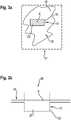
Erfindungsgemäß ist eine Anordnung für ein Fahrzeug vorgesehen, wobei die Anordnung mindestens ein Fahrzeugbauteil, wie beispielsweise einen Kotflügel oder eine Motorhaube oder eine Fahrzeugtür, aufweist. Des Weiteren weist die Anordnung zumindest ein optisches Element, wie beispielsweise einen Lichtleiter oder einen Reflektor, und/oder eine Lichtquelle auf. Das heißt, das Licht der Lichtquelle kann in das optische Element einkoppeln oder die Lichtquelle kann ohne das optische Element vorliegen. Des Weiteren bildet eine Außenfläche des Fahrzeugbauteils oder das Fahrzeugbauteil und eine Lichtauskoppelfläche des optischen Elements oder eine Lichtauskoppelfläche der Lichtquelle eine gemeinsame und/oder durchgängige und/oder einheitliche Fläche aus. Das heißt, die Lichtquelle oder das optische Element sind derart in das Fahrzeugbauteil oder in einen Teil/Abschnitt des Fahrzeugbauteils integriert oder mit diesem verbunden oder in das Fahrzeugbauteil oder in den Teil/Abschnitt des Fahrzeugbauteils aufgenommen, sodass eine gemeinsame und/oder ebene und/oder plane Fläche von der Lichtauskoppelfläche der Lichtquelle oder der Lichtauskoppelfläche des optischen Elements und einer Außenfläche des Fahrzeugbauteils gebildet ist. Des Weiteren ist die Fläche, die von dem Fahrzeugbauteil und der Lichtquelle oder dem optischen Element gebildet ist, mit einer lichtundurchlässigen Schicht, wie beispielsweise einem Lack, insbesondere einem Fahrzeuglack, versehen. Des Weiteren ist zumindest ein Abschnitt der Schicht in einem Bereich der Lichtauskoppelfläche des optischen Elements oder der Lichtauskoppelfläche der Lichtquelle perforiert. Mit anderen Worten ist die lichtundurchlässige Schicht zumindest teilweise in dem Abschnitt, der in dem Bereich der Lichtauskoppelfläche des optischen Elements oder der Lichtauskoppelfläche der Lichtquelle ist, abgetragen. Eine Perforation kann vorzugweise derart erfolgen, dass bei einer nicht eingeschalteten Lichtquelle die Perforation oder die Abtragung nicht oder zumindest kaum sichtbar ist.According to the invention, an arrangement for a vehicle is provided, the arrangement having at least one vehicle component, such as a fender or a hood or a vehicle door. Furthermore, the arrangement has at least one optical element, such as, for example, a light guide or a reflector, and / or a light source. That is, the light from the light source can couple into the optical element or the light source can be present without the optical element. Furthermore, an outer surface of the vehicle component or the vehicle component and a light coupling-out surface of the optical element or a light coupling-out surface of the light source form a common and / or continuous and / or uniform surface. That is, the light source or the optical element are integrated in the vehicle component or in a part / section of the vehicle component or connected to it or incorporated in the vehicle component or in the part / section of the vehicle component, so that a common and / or flat and / or planar surface is formed by the light coupling-out surface of the light source or the light coupling-out surface of the optical element and an outer surface of the vehicle component. Furthermore, the surface which is formed by the vehicle component and the light source or the optical element is provided with an opaque layer, such as a paint, in particular a vehicle paint. Furthermore, at least a section of the layer is perforated in a region of the light coupling-out surface of the optical element or the light coupling-out surface of the light source. In other words, the opaque layer is at least partially removed in the section that is in the region of the light coupling-out surface of the optical element or the light coupling-out surface of the light source. A perforation can preferably take place in such a way that, when the light source is not switched on, the perforation or the ablation is not or at least barely visible.
Ein Vorteil dieser Anordnung ist, dass auf vorrichtungstechnisch einfache und kostengünstiger Weise eine optisch ästhetisch anmutende Beleuchtung des Fahrzeugbauteils möglich ist. Durch eine geeignete Ausbildung des Abschnitts der Schicht, der perforiert ist, kann kostengünstig ein leuchtendes Symbol oder Zeichen, beispielsweise ein leuchtendes Logo, insbesondere ein leuchtendes Herstellerlogo, erzeugt sein. Auch Warnsymbole oder andere Symbole oder Nachrichten oder Anzeigen können mit der Anordnung vorrichtungstechnisch einfach und kostengünstig umgesetzt werden. Beispielsweise kann das Fahrzeugbauteil eine Kofferraumklappe und/oder eine Heckklappe sein und durch die Anordnung kann beispielsweise bei eingeschalteter Lichtquelle, beispielsweise bei einer Gefahrensituation, ein Warnsymbol für andere Verkehrsteilnehmer erzeugt werden. Des Weiteren ist es möglich, dass das Fahrzeugteil beispielsweise eine Frontstoßstange ist, und somit das Markenlogo des Fahrzeugs als leuchtendes Symbol durch die Anordnung dargestellt werden kann. Dies schafft Aufmerksamkeit und somit kann sich ein Fahrzeug designtechnisch von anderen Fahrzeugen unterscheiden.One advantage of this arrangement is that it is possible to illuminate the vehicle component in a manner that is simple and inexpensive in terms of device technology. By suitably designing the section of the layer that is perforated, a luminous symbol or sign, for example a luminous logo, in particular a luminous manufacturer's logo, can be generated at low cost. Warning symbols or other symbols or messages or displays can also be implemented simply and inexpensively with the arrangement in terms of device technology. For example, the vehicle component can be a trunk lid and / or a tailgate and the arrangement can generate a warning symbol for other road users when the light source is switched on, for example in a dangerous situation. Furthermore, it is possible that the vehicle part is, for example, a front bumper, and thus the brand logo of the vehicle can be represented as a luminous symbol by the arrangement. This attracts attention and thus a vehicle can differ from other vehicles in terms of design.
Durch die Perforation kann ein Muster oder ein Zeichen oder ein Symbol erzeugt werden, welches beispielsweise aus einzelnen Subelementen zusammengesetzt ist, wie zum Beispiel Quadraten und/oder Kreisen und/oder Rechtecken oder Hexagons. Es kann die gesamte Lichtauskoppelfläche des optischen Elements oder der Lichtquelle perforiert sein. Es ist auch möglich, dass der perforierte Abschnitt der Schicht den Bereich der Lichtauskoppelfläche des optischen Elements oder der Lichtquelle nur teilweise umfasst. Ein Zeichen oder ein Symbol oder ein Muster kann auch aus mehreren perforierten Abschnitten ausgebildet sein, die nicht miteinander verbunden sind.The perforation can be used to generate a pattern or a character or a symbol which is composed, for example, of individual sub-elements, such as, for example, squares and / or circles and / or rectangles or hexagons. It can cover the entire light output surface of the optical element or the light source be perforated. It is also possible that the perforated section of the layer only partially encompasses the area of the light coupling-out surface of the optical element or of the light source. A character or a symbol or a pattern can also be formed from a plurality of perforated sections which are not connected to one another.
Das optische Element und das Fahrzeugbauteil sind vorzugsweise einstückig ausgebildet. Beispielsweise können das Fahrzeugbauteil und das optische Element in einem Spritzgussverfahren hergestellt sein. Das Fahrzeugbauteil und das optische Element können beispielsweise aus einem transparenten oder zumindest halbtransparenten Kunststoff spritzgegossen sein. Des Weiteren ist es möglich, das Fahrzeugbauteil und das optische Element in einem Zwei-Komponenten-Spritzgussverfahren herzustellen. Beispielsweise kann das Fahrzeugbauteil aus einem nicht transparenten Kunststoff und das optische Element aus einem zumindest halbtransparenten oder transparenten Kunststoff hergestellt sein. Es ist auch möglich, beispielsweise, wenn das optische Element ein Reflektor ist, dass das optische Element bei einem Spritzgussverfahren des Fahrzeugbauteils in ein Spritzgusswerkzeug zur Herstellung des Fahrzeugbauteils eingelegt wird und umgossen wird, sodass das Fahrzeugbauteil und das optische Element einstückig ausgebildet sind. Weiter denkbar wäre, dass das Fahrzeugbauteil und das optische Element über ein additives Fertigungsverfahren, wie zum Beispiels 3D-Druck, hergestellt werden. Hierbei könnten beispielsweise für das Fahrzeugbauteil und das optische Element unterschiedliche Materialien verwendet werden.The optical element and the vehicle component are preferably formed in one piece. For example, the vehicle component and the optical element can be produced in an injection molding process. The vehicle component and the optical element can, for example, be injection molded from a transparent or at least semi-transparent plastic. It is also possible to manufacture the vehicle component and the optical element in a two-component injection molding process. For example, the vehicle component can be made from a non-transparent plastic and the optical element can be made from an at least semi-transparent or transparent plastic. It is also possible, for example if the optical element is a reflector, for the optical element to be inserted into an injection molding tool for producing the vehicle component during an injection molding process of the vehicle component and to be encapsulated so that the vehicle component and the optical element are formed in one piece. It would also be conceivable that the vehicle component and the optical element are manufactured using an additive manufacturing process, such as 3D printing, for example. Here, for example, different materials could be used for the vehicle component and the optical element.
Das optische Element hat vorzugsweise eine Einkoppelfläche für Licht der Lichtquelle. Die Einkoppelfläche kann derart ausgestaltet sein und die Lichtquelle derart angeordnet sein, dass das Licht weg von der Lichtauskoppelfläche und/oder hin zu der Lichtauskoppelfläche einkoppelbar ist. Beispielsweise kann die Einkoppelfläche derart ausgebildet sein und die Lichtquelle derart angeordnet sein, dass das Licht der Lichtquelle parallel oder entlang zu der gemeinsamen Fläche des Fahrzeugbauteils und des optischen Elements einkoppelbar ist. Es ist in einem weiteren Ausführungsbeispiel möglich, dass das Licht der Lichtquelle senkrecht zu der gemeinsamen Fläche oder direkt auf die Lichtauskoppelfläche einkoppelbar ist. Somit kann die Lichtquelle, deren Licht in die Einkoppelfläche einkoppelt, an verschiedenen Positionen angeordnet sein, sodass die Anordnung beispielsweise auch bei einem engen oder kleinen Bauraum eingesetzt werden kann. Ist das Fahrzeugbauteil beispielsweise eine Fahrzeugtür, so ist es insbesondere vorteilhaft, wenn das Licht der Lichtquelle über die Einkoppelfläche insbesondere entlang oder parallel zur gemeinsamen Fläche einkoppelbar ist, da somit die Anordnung insgesamt in einer Richtung senkrecht oder vertikal zu der gemeinsamen Fläche klein sein kann, das heißt, eine Tiefe des optischen Elements von der lichtundurchlässigen Schicht aus gesehen, kann klein sein. Dies ist vorteilhaft, da beispielsweise eine Fahrzeugtür in der Richtung senkrecht zu der gemeinsamen Fläche ebenfalls klein ausgebildet ist, das heißt ebenfalls eine geringe Tiefe aufweist. Ist das Fahrzeugbauteil beispielsweise eine Stoßstange, die beispielsweise eine Mehrzahl von Sensoren aufweist, so ist es möglich, dass der Bauraum parallel oder entlang zu der gemeinsamen Fläche beschränkt ist, und somit kann die Einkoppelfläche derart ausgebildet sein, dass das Licht hin zu der Lichtauskoppelfläche, insbesondere senkrecht zu der gemeinsamen Fläche, einkoppelbar ist.The optical element preferably has a coupling surface for light from the light source. The coupling-in surface can be configured and the light source can be arranged such that the light can be coupled in away from the light coupling-out surface and / or towards the light coupling-out surface. For example, the coupling surface can be designed and the light source can be arranged such that the light from the light source can be coupled in parallel to or along the common surface of the vehicle component and the optical element. In a further exemplary embodiment, it is possible for the light from the light source to be able to be coupled in perpendicular to the common surface or directly onto the light coupling-out surface. Thus, the light source, the light of which is coupled into the coupling surface, can be arranged at different positions, so that the arrangement can also be used, for example, in a narrow or small installation space. If the vehicle component is, for example, a vehicle door, it is particularly advantageous if the light from the light source can be coupled in via the coupling surface, in particular along or parallel to the common surface, since the arrangement can thus be small overall in a direction perpendicular or vertical to the common surface, that is, a depth of the optical element viewed from the opaque layer can be small. This is advantageous because, for example, a vehicle door is also designed to be small in the direction perpendicular to the common surface, that is to say also has a small depth. If the vehicle component is, for example, a bumper that has a plurality of sensors, for example, it is possible that the installation space is limited parallel to or along the common surface, and thus the coupling-in surface can be designed in such a way that the light is directed towards the light-coupling-out surface, in particular perpendicular to the common surface, can be coupled.
Das optische Element kann vorzugsweise von der Schicht wegkragen, insbesondere in Richtung Fahrzeuginnenseite, so dass das optische Element vorteilhafterweise von einem Betrachter von außen nicht sichtbar ist. Beispielsweise kann das optische Element blockförmig oder quaderförmig oder boxförmig oder trapezförmig oder tulpenförmig ausgebildet sein und von der Schicht wegkragen. Ist das Licht parallel oder entlang zu der gemeinsamen Fläche in das optische Element eingekoppelt, so kann beispielsweise zumindest eine Fläche des optischen Elements, die sich, insbesondere in etwa senkrecht, von der Lichtauskoppelfläche in das Fahrzeuginnere erstreckt und/oder sich von der Schicht weg erstreckt, eine Einkoppelfläche sein. Ist das Licht hin zu der Lichtauskoppelfläche in das optische Element eingekoppelt, so kann eine Fläche des optischen Elements, das der Lichtauskoppelfläche zugewandt ist, eine Einkoppelfläche sein.The optical element can preferably protrude away from the layer, in particular in the direction of the inside of the vehicle, so that the optical element is advantageously not visible to an observer from the outside. For example, the optical element can be block-shaped or cuboid or box-shaped or trapezoidal or tulip-shaped and protrude away from the layer. If the light is coupled into the optical element parallel or along the common surface, for example at least one surface of the optical element that extends, in particular approximately perpendicular, from the light output surface into the vehicle interior and / or extends away from the layer , be a coupling surface. If the light is coupled into the optical element towards the light coupling-out surface, a surface of the optical element which faces the light coupling-out surface can be a coupling-in surface.
In einer bevorzugten Ausgestaltung ist das optische Element als Block oder blockförmig oder als Substrat oder substratförmig ausgebildet. Des Weiteren hat das blockförmige optische Element vorzugsweise eine Umfangsfläche, die sich von der gemeinsamen Fläche oder der Schicht, insbesondere in Richtung Fahrzeuginneres, wegerstreckt. Die Umfangsfläche kann zwischen der gemeinsamen Fläche und einer Bodenfläche oder Stirnfläche des optischen Elements ausgebildet sein, die gegenüber der gemeinsamen Fläche oder der Lichtauskoppelfläche angeordnet ist. Zumindest ein Abschnitt der Umfangsfläche und/oder der Bodenfläche kann als die Einkoppelfläche dienen. Zwischen der Bodenfläche und der Umfangsfläche kann eine Kante ausgebildet sein. Es ist auch möglich, dass die Umfangsfläche und die Bodenfläche ohne Kante dazwischen ausgebildet sind. Beispielsweise kann das optische Element dann eine kuppelförmige oder halbkugelförmige Grundform aufweisen.In a preferred embodiment, the optical element is designed as a block or block-shaped or as a substrate or substrate-shaped. Furthermore, the block-shaped optical element preferably has a circumferential surface which extends away from the common surface or the layer, in particular in the direction of the interior of the vehicle. The circumferential surface can be formed between the common surface and a bottom surface or end surface of the optical element which is arranged opposite the common surface or the light coupling-out surface. At least a section of the circumferential surface and / or the bottom surface can serve as the coupling surface. An edge can be formed between the bottom surface and the peripheral surface. It is also possible that the circumferential surface and the bottom surface are formed without an edge therebetween. For example, the optical element can then have a dome-shaped or hemispherical basic shape.
Die Umfangsfläche des blockförmigen optischen Elements kann von dem Fahrzeugbauteil in einem Bereich bis zu einer vorbestimmten Tiefe von dem Fahrzeugbauteil teilweise oder vollständig umfasst oder umgeben sein. In einem bevorzugten Ausführungsbeispiel kann das optische Element bis zu einer bestimmten Tiefe einstückig mit dem Fahrzeugbauteil verbunden sein, sodass das Fahrzeugbauteil und das optische Element einstückig ausgebildet sind. In einem Bereich, der sich dem Bereich, der von dem Fahrzeugbauteil umfasst ist oder der mit dem Fahrzeugbauteil verbunden ist, in Richtung Fahrzeuginneres anschließt, kann die Umfangsfläche zumindest teilweise oder vollständig frei liegen. Mindestens ein Abschnitt des freiliegenden Bereichs kann als die Einkoppelfläche dienen. Die Tiefe des optischen Elements in Richtung Fahrzeuginneres kann derart gewählt werden, dass sich das Licht insbesondere gleichmäßig in dem optischen Element verteilt, und somit eine Lichtintensität des aus der Lichtauskoppelfläche austretenden Lichts besonders gleichmäßig ist. Die Tiefe kann jedoch auch abhängig vom vorhandenen Bauraum gewählt werden. Insbesondere wird die Tiefe derart ausgelegt, dass diese mit einer Homogenitätsanforderung einer Lichtverteilung aus der Lichtauskoppelfläche kompatibel ist.The peripheral surface of the block-shaped optical element can be from the vehicle component in FIG be partially or completely encompassed or surrounded by the vehicle component in an area up to a predetermined depth. In a preferred exemplary embodiment, the optical element can be connected in one piece to the vehicle component up to a certain depth, so that the vehicle component and the optical element are formed in one piece. In a region that adjoins the region that is encompassed by the vehicle component or that is connected to the vehicle component in the direction of the vehicle interior, the circumferential surface can be at least partially or completely free. At least a section of the exposed area can serve as the coupling surface. The depth of the optical element in the direction of the interior of the vehicle can be selected in such a way that the light is distributed, in particular, evenly in the optical element, and thus a light intensity of the light emerging from the light decoupling surface is particularly uniform. However, the depth can also be selected depending on the available installation space. In particular, the depth is designed in such a way that it is compatible with a homogeneity requirement for a light distribution from the light decoupling surface.
Mit Vorteil ist die zumindest eine Lichtquelle in einer Richtung senkrecht zur Schicht gesehen zwischen der Bodenfläche und der Schicht angeordnet und somit gegenüberliegend von der Umfangsfläche vorgesehen. Alternativ oder zusätzlich ist denkbar, dass die zumindest eine Lichtquelle oder eine weitere Lichtquelle gegenüberliegend von der Bodenfläche vorgesehen ist.The at least one light source is advantageously arranged between the bottom surface and the layer, seen in a direction perpendicular to the layer, and is thus provided opposite the circumferential surface. Alternatively or additionally, it is conceivable that the at least one light source or a further light source is provided opposite the bottom surface.
Des Weiteren kann das optische Element zumindest eine Einkoppelstruktur für Licht der Lichtquelle aufweisen. Die Einkoppelstruktur weist vorzugsweise die Einkoppelfläche auf, das heißt, die Einkoppelfläche kann ein Teil der Einkoppelstruktur sein. Vorzugsweise verbreitert sich die Einkoppelstruktur ausgehend von der Einkoppelfläche. Dies ist vorteilhaft, da somit eine Lichtverteilung in dem optischen Element besonders gleichmäßig ist. Des Weiteren kann die Einkoppelstruktur zumindest eine, insbesondere konkave, insbesondere stirnseitige Aussparung haben, wobei diese vorzugsweise die Einkoppelfläche bildet. Durch die Einkoppelstruktur kann Licht mit einer gleichmäßigen Verteilung in das optische Element eingeleitet werden, sodass eine Lichtintensität von Licht, das aus der Lichtauskoppelfläche auskoppelt, ebenfalls möglichst gleichmäßig ist. Auch eine effizientere Verwendung des Lichtes der Lichtquelle ist dadurch möglich. Des Weiteren kann durch die Einkoppelstruktur Licht der Lichtquelle zu dem optischen Element geführt werden, wenn beispielsweise der vorhandene Bauraum, in dem das optische Element angeordnet ist, zu klein ist, um direkt an dem optischen Element eine Lichtquelle anzubringen. Die Oberfläche der Einkoppelstruktur ist vorzugsweise ein Teil der Umfangsfläche des optischen Elements oder der Bodenfläche des optischen Elements.Furthermore, the optical element can have at least one coupling structure for light from the light source. The coupling-in structure preferably has the coupling-in surface, that is to say the coupling-in surface can be part of the coupling-in structure. The coupling-in structure preferably widens starting from the coupling-in surface. This is advantageous because a light distribution in the optical element is particularly uniform. Furthermore, the coupling structure can have at least one, in particular concave, in particular frontal recess, this preferably forming the coupling surface. Through the coupling structure, light can be introduced into the optical element with a uniform distribution, so that a light intensity of light that is coupled out from the light output surface is also as uniform as possible. A more efficient use of the light from the light source is also possible as a result. Furthermore, through the coupling structure, light from the light source can be guided to the optical element if, for example, the existing installation space in which the optical element is arranged is too small to attach a light source directly to the optical element. The surface of the coupling structure is preferably part of the circumferential surface of the optical element or the bottom surface of the optical element.
Die Einkoppelstruktur kann in einem Ausführungsbeispiel als ein, insbesondere zylindrischer oder als ein gekrümmter, Einkopplungslichtleiter mit einem beispielsweise runden Querschnitt ausgebildet sein. Dieser kann beispielsweise zumindest eine Krümmung in seiner Längsrichtung aufweisen. Eine Innenwandung des Einkopplungslichtleiter kann das Licht von einer Einkoppelfläche, die insbesondere eine Endfläche oder Stirnfläche des Einkopplungslichtleiters ist, zu dem optischen Element leiten. Der Einkopplungslichtleiter ist vorzugsweise abhängig von Bauverhältnissen und von TIR-(total internal reflection-)Winkeln so gut wie möglich ausgelegt. Das heißt, der Einkopplungslichtleiter ist vorzugsweise derart ausgelegt, dass eine Mantelfläche des Einkopplungslichtleiter vorzugsweise eine TIR-Fläche ist. Es ist auch möglich, dass die Mantelfläche des Einkopplungslichtleiters reflektierend oder verspiegelt ausgebildet ist, indem beispielsweise an der Mantelfläche eine Reflexionsfolie vorgesehen ist. Der Einkopplungslichtleiter kann beispielsweise rotationsymmetrisch sein oder auch nicht rotationsymmetrisch, beispielsweise mit einem ovalen Querschnitt ausgebildet sein. Es ist auch möglich, dass der Einkopplungslichtleiter freiförmig ausgebildet ist. Das heißt, beispielsweise kann dieser einen sich in der Längsrichtung des Einkopplungslichtleiters verändernden Querschnitt haben. Der Einkopplungslichtleiter kann vorzugsweise an dem optischen Element ausgebildet sein, wenn ein Bauraum eine direkte Einkopplung in das optische Element nicht zulässt, das heißt wenn der Bauraum für eine Anordnung einer Lichtquelle direkt oder nahe an dem optischen Element zu klein ist.In one exemplary embodiment, the coupling-in structure can be designed as a, in particular cylindrical, or as a curved, coupling-in light guide with, for example, a round cross-section. This can for example have at least one curvature in its longitudinal direction. An inner wall of the coupling-in light guide can guide the light from a coupling-in surface, which is in particular an end face or end face of the coupling-in light guide, to the optical element. The coupling light guide is preferably designed as well as possible depending on the structural conditions and TIR (total internal reflection) angles. That is to say, the coupling-in light guide is preferably designed in such a way that a lateral surface of the coupling-in light guide is preferably a TIR surface. It is also possible for the outer surface of the coupling-in light guide to be reflective or reflective, for example in that a reflective film is provided on the outer surface. The coupling-in light guide can for example be rotationally symmetrical or not rotationally symmetrical, for example with an oval cross-section. It is also possible for the coupling-in light guide to be of free-form design. That is to say, for example, this can have a cross section that changes in the longitudinal direction of the coupling-in light guide. The coupling-in light guide can preferably be formed on the optical element if an installation space does not permit direct coupling into the optical element, that is, if the installation space is too small for an arrangement of a light source directly or close to the optical element.
Des Weiteren kann die Einkoppelstruktur in einem weiteren Ausführungsbeispiel ein Kollimator sein, insbesondere ein TIR-(total internal reflection-)Kollimator, sodass das Licht optimal und effizient in das optische Element einkoppeln kann und sich gleichmäßig in dem optischen Element ausbreitet, sodass eine Lichtintensität des Lichtes, das aus der Lichtauskoppelfläche des optischen Elements auskoppelt, gleichmäßig ist. Der Kollimator kann in einem Ausführungsbeispiel einen direkt abbildenden Linsenteil in seiner Mitte aufweisen.Furthermore, in a further exemplary embodiment, the coupling structure can be a collimator, in particular a TIR (total internal reflection) collimator, so that the light can optimally and efficiently couple into the optical element and spread evenly in the optical element, so that a light intensity of the Light that is decoupled from the light decoupling surface of the optical element is uniform. In one embodiment, the collimator can have a directly imaging lens part in its center.
Es ist bevorzugt, dass das optische Element und die Einkoppelstruktur einstückig ausgebildet und gefertigt sind, das heißt, beispielsweise gemeinsam urgeformt sind, beispielsweise durch Spritzgießen. Es ist jedoch auch möglich, insbesondere, wenn die Einkoppelstruktur eine komplexe Struktur aufweist, dass das optische Element und die Einkoppelstruktur getrennt voneinander gefertigt sind und anschließend form- und/oder stoff- und/oder kraftschlüssig verbunden sind. Dies ist vorteilhaft, da somit leichter Entformungsschrägen in einem Spritzgusswerkzeug umsetzbar sind, mit dem die Einkoppelstruktur oder das optische Element ausgebildet sein können. Sind das optische Element und die Einkoppelstruktur getrennt voneinander ausgebildet, so ist es vorteilhaft, wenn eine Indexanpassung (Index Matching Kit) zwischen dem optischen Element und der Einkoppelstruktur vorgesehen ist. Dies ist vorteilhaft um Verluste im Übergang zwischen den beiden Materialien zu minimieren.It is preferred that the optical element and the coupling structure are designed and manufactured in one piece, that is to say, for example, are originally molded together, for example by injection molding. However, it is also possible, in particular if the coupling structure has a complex structure, for the optical element and the coupling structure to be manufactured separately from one another and then connected in a form-fitting and / or material-fit and / or force-fitting manner. This is advantageous as it is easier draft bevels can be implemented in an injection molding tool with which the coupling structure or the optical element can be formed. If the optical element and the coupling structure are formed separately from one another, it is advantageous if an index matching kit is provided between the optical element and the coupling structure. This is advantageous in order to minimize losses in the transition between the two materials.
Das optische Element kann aus lichtleitenden Material ausgebildet sein. Das heißt, das optische Element kann beispielsweise ein Lichtleiter oder ein Taper (sich zur Lichtquelle verjüngendes optisches Element) oder ein Mixing Rod (Mischstab) sein.The optical element can be formed from light-conducting material. That is to say, the optical element can be, for example, a light guide or a taper (an optical element that tapers towards the light source) or a mixing rod.
Das optische Element, das beispielsweise ein Lichtleiter ist, kann beispielsweise aus einem transparenten Kunststoff, wie beispielsweise Silikon oder PC (Polycarbonat), oder aus einem sonstigen transparenten und/oder lichtdurchlässigen Material ausgebildet sein, und in den Lichtleiter eingekoppeltes Licht, kann von der Einkoppelfläche bis zur Lichtauskoppelfläche geführt sein. Der Kunststoff oder das Material, aus dem das optische Element ausgebildet ist, kann in einem Ausführungsbeispiel getönt sein, wobei die Tönung insbesondere spektral an die Lichtquelle angepasst sein kann. Der Lichtleiter kann sich von der Lichtauskoppelfläche wegerstrecken, insbesondere mit einer beliebigen Form.The optical element, which is a light guide, for example, can be made from a transparent plastic, such as silicone or PC (polycarbonate), or from another transparent and / or translucent material, and light coupled into the light guide can come from the coupling surface be performed up to the light extraction surface. In one exemplary embodiment, the plastic or the material from which the optical element is formed can be tinted, wherein the tint can in particular be spectrally adapted to the light source. The light guide can extend away from the light coupling-out surface, in particular with any shape.
Des Weiteren kann das optische Element, das insbesondere aus einem lichtleitenden Material ausgebildet ist, zumindest eine Elementfläche haben, die vorzugsweise nicht die Einkoppelfläche und nicht die Lichtauskoppelfläche ist. Die Elementfläche ist beispielsweise ein Abschnitt der Umfangsfläche und/oder ein Abschnitt der Bodenfläche. Denkbar wäre auch, dass die Elementfläche die gesamte Umfangsfläche und/oder Bodenfläche bildet (bis auf die Einkoppelfläche/n). Die Elementfläche kann derart ausgebildet sein, dass Licht, das auf dieser auftritt, zu der Lichtauskoppelfläche gelenkt ist. Es ist vorteilhaft, wenn das optische Element derart ausgebildet ist, dass das in das optische Element eingekoppelte Licht vorzugsweise ausschließlich oder im Wesentlichen vollständig aus der Lichtauskoppelfläche austritt. Um eine parasitäre Lichtauskopplung zu vermeiden, ist vorzugsweise die Elementfläche, die sich von der Lichtauskoppelfläche unterscheidet, derart ausgebildet, dass Licht von dieser reflektiert ist und nicht aus dieser Fläche austritt. Es können insbesondere alle Flächen Elementflächen sein, die nicht als die Lichtauskoppelflächen oder als die Einkoppelfläche ausgebildet sind.Furthermore, the optical element, which is formed in particular from a light-conducting material, can have at least one element surface, which is preferably not the coupling-in surface and not the light-coupling-out surface. The element surface is, for example, a section of the circumferential surface and / or a section of the bottom surface. It would also be conceivable that the element surface forms the entire circumferential surface and / or bottom surface (except for the coupling surface (s)). The element surface can be designed in such a way that light that occurs on it is directed to the light coupling-out surface. It is advantageous if the optical element is designed in such a way that the light coupled into the optical element preferably emerges exclusively or essentially completely from the light output surface. In order to avoid parasitic light outcoupling, the element surface which differs from the light outcoupling surface is preferably designed in such a way that light is reflected by it and does not exit from this surface. In particular, all surfaces can be element surfaces that are not designed as the light coupling-out surfaces or as the coupling-in surface.
Die Elementfläche kann zumindest teilweise mit einer reflektierenden Folie, insbesondere von außen, beschichtet sein. Beispielsweise ist die Elementfläche mit einer Metallschicht bedampft. Die Elementfläche, die beschichtet ist, kann beispielsweise eine der Flächen oder zumindest die eine Fläche sein, die sich von der Schicht in Richtung Fahrzeuginneres erstreckt, also beispielsweise die Umfangsfläche. Es ist auch möglich, dass eine Fläche, die der Lichtauskoppelfläche zugewandt ist und/oder dieser gegenüberliegt, reflektierend ausgebildet ist, also beispielsweise die Bodenfläche.The element surface can be at least partially coated with a reflective film, in particular from the outside. For example, the element surface is vapor-deposited with a metal layer. The element surface that is coated can be, for example, one of the surfaces or at least the one surface that extends from the layer in the direction of the vehicle interior, that is to say, for example, the circumferential surface. It is also possible for a surface facing the light coupling-out surface and / or opposite it to be reflective, that is to say, for example, the bottom surface.
Zusätzlich oder alternativ kann das optische Element zumindest eine Auskoppelstrukturfläche aufweisen, die zumindest eine Auskoppelstruktur hat. Die Auskoppelstrukturfläche liegt beispielsweise der Lichtauskoppelfläche gegenüber. Die Auskoppelstrukturfläche kann zumindest einen Abschnitt der Bodenfläche bilden. Die Lichtauskoppelfläche und die Auskoppelstrukturfläche können einander zugewandt sein. Die Auskoppelstrukturfläche kann beispielsweise parallel oder etwa parallel zur Lichtauskoppelfläche angeordnet sein. Insbesondere weist die Auskoppelstrukturfläche eine Mehrzahl oder Vielzahl von Auskoppelstrukturen auf. Beispielsweise können eine Mehrzahl von Auskoppelstrukturen gebildet sein, indem die Auskoppelstrukturfläche, insbesondere von außen, aufgeraut und/oder teilweise aufgeraut sein kann. Es ist auch möglich, dass, insbesondere wenn das optische Element ein Lichtleiter ist, die Auskoppelstruktur oder zumindest eine der Auskoppelstrukturen eine z.B. prismenförmige Auskragung oder Ausbeulung ist, die von dem optischen Element auskragt. Des Weiteren kann die zumindest eine Auskoppelstruktur eine Aussparung sein, die in das optische Element einkragt. Die Aussparung oder Ausbeulung kann pyramidenförmig oder zylinderförmig oder halbkugelförmig oder teilkugelförmig sein. Die zumindest eine Auskoppelstruktur kann direkt beim Urformen, beispielsweise in dem Spritzgusswerkzeugs, des optischen Elements vorgesehen sein, sodass eine Herstellung des optischen Elements besonders kostengünstig sein kann. Die Mehrzahl von Auskoppelstrukturen kann in der Auskoppelstrukturfläche periodisch oder aperiodisch oder auch vollkommen zufällig angeordnet sein. Die Größe einer der Auskoppelstrukturen oder der Auskoppelstruktur ist insbesondere klein im Vergleich zu einer Abmessung des Abschnitts der Schicht, der perforiert ist. Mit anderen Worten ist der Abschnitt der Schicht, der perforiert ist, größer als die zumindest eine Auskoppelstruktur. Es ist also möglich, dass mehrere zehn bis mehrere hundert Auskoppelstrukturen in der Auskopplungsstrukturfläche vorgesehen sind. Es ist auch möglich, dass Mikrostrukturen verwendet werden. Dies ist vorteilhaft, da somit eine besonders gleichmäßige Auskopplung des Lichts aus der Lichtauskoppelfläche erreicht werden kann.Additionally or alternatively, the optical element can have at least one coupling-out structure surface which has at least one coupling-out structure. The outcoupling structure surface lies opposite the light outcoupling surface, for example. The decoupling structure surface can form at least a portion of the bottom surface. The light outcoupling surface and the outcoupling structure surface can face one another. The coupling-out structure surface can be arranged, for example, parallel or approximately parallel to the light coupling-out surface. In particular, the coupling-out structure area has a plurality or multiplicity of coupling-out structures. For example, a plurality of coupling-out structures can be formed in that the coupling-out structure surface can be roughened and / or partially roughened, in particular from the outside. It is also possible, in particular when the optical element is a light guide, that the coupling-out structure or at least one of the coupling-out structures is, for example, a prism-shaped projection or bulge that protrudes from the optical element. Furthermore, the at least one coupling-out structure can be a cutout which protrudes into the optical element. The recess or bulge can be pyramid-shaped or cylindrical or hemispherical or part-spherical. The at least one coupling-out structure can be provided directly during the primary molding, for example in the injection molding tool, of the optical element, so that production of the optical element can be particularly cost-effective. The plurality of coupling-out structures can be arranged periodically or aperiodically or completely randomly in the coupling-out structure surface. The size of one of the coupling-out structures or the coupling-out structure is particularly small compared to a dimension of the section of the layer that is perforated. In other words, the section of the layer that is perforated is larger than the at least one coupling-out structure. It is therefore possible for several tens to several hundred coupling-out structures to be provided in the coupling-out structure area. It is also possible that microstructures are used. This is advantageous because a particularly uniform coupling-out of the light from the light coupling-out surface can be achieved in this way.
Zusätzlich kann die Auskoppelstrukturfläche mit einer reflektierenden Folie versehen sein und/oder eine Metallisierung, beispielsweise durch Bedampfung, aufweisen. Die Bedampfung oder die Folie kann auf einer von der Lichtauskoppelseite wegweisenden Seite aufgebracht sein oder beim Urformen des optischen Elements vergossen sein. Dies ist vorteilhaft, dass somit eine höhere Effizienz der Anordnung erreicht werden kann und keine parasitäre Lichtauskopplung über die Auskoppelstrukturfläche möglich ist. Es ist auch möglich die Zwischenbereiche zwischen den einzelnen Auskoppelstrukturen von der der Lichtauskoppelseite wegweisenden Seite aufgeraut sind und/oder hochdiffus reflektiv weiß ausgestaltet sind.In addition, the coupling-out structure surface can be provided with a reflective film and / or a metallization, for example through Vapor deposition. The vapor deposition or the film can be applied to a side facing away from the light coupling-out side or it can be encapsulated during the primary molding of the optical element. This is advantageous in that a higher efficiency of the arrangement can thus be achieved and no parasitic light decoupling via the decoupling structure surface is possible. It is also possible that the intermediate areas between the individual decoupling structures are roughened from the side facing away from the light decoupling side and / or are designed to be highly diffuse reflective white.
Das optische Element kann in einem Ausführungsbeispiel beispielsweise zumindest eine Wandung, insbesondere eine Mehrzahl von Wandungen, aufweisen, die reflektierend ist/sind. Mit anderen Worten kann das optische Elemente als ein Reflektor ausgebildet sein, wobei die zumindest eine Wandung eine Reflektorwand ist. Der Reflektor kann derart ausgebildet sein, dass sich die zumindest eine Wandung sich von der Schicht weg erstreckt. Der Reflektor kann beispielsweise ein CPC-(compound parabolic concentrators)-Reflektor sein. Das Licht, das über die Einkoppelfläche, die an der zumindest einen Wandung angeordnet ist, einkoppelt, kann von der Wandung reflektiert werden, und zu der Lichtauskoppelfläche geführt werden. Beispielsweise kann das optische Element fünf Wandungen aufweisen, wobei sich vier Wandungen von der Schicht weg erstrecken und eine Wandung der Schicht und somit der Lichtauskoppelfläche zugewandt ist. Beispielsweise kann eine der Wandungen, die sich insbesondere von der Schicht wegerstreckt, die Einkoppelfläche aufweisen oder an dieser kann die Einkoppelstruktur ausgebildet sein. Mit dieser Konfiguration ist das optische Element als, insbesondere hohler, blockförmiger Reflektor ausgebildet. Es ist auch möglich, dass sich eine Wandung mit einer zylindrischen Grundform von der Schicht wegerstreckt und eine weitere Wandung in etwa parallel zu der Lichtauskoppelfläche wegerstreckt, das heißt der Lichtauskoppelfläche zugewandt ist. Eine der Wandungen kann insbesondere die Einkoppelfläche und/oder die Einkoppelstruktur aufweisen. In einem weiteren Ausführungsbeispiel kann die Wandung halbkugelförmig oder schalenförmig ausgebildet sein.In one exemplary embodiment, the optical element can, for example, have at least one wall, in particular a plurality of walls, which is / are reflective. In other words, the optical element can be designed as a reflector, the at least one wall being a reflector wall. The reflector can be designed in such a way that the at least one wall extends away from the layer. The reflector can be, for example, a CPC (compound parabolic concentrators) reflector. The light that is coupled in via the coupling-in surface, which is arranged on the at least one wall, can be reflected by the wall and guided to the light-coupling-out surface. For example, the optical element can have five walls, four walls extending away from the layer and one wall facing the layer and thus the light coupling-out surface. For example, one of the walls, which in particular extends away from the layer, can have the coupling-in surface, or the coupling-in structure can be formed on this. With this configuration, the optical element is designed as, in particular, a hollow, block-shaped reflector. It is also possible for a wall with a cylindrical basic shape to extend away from the layer and for a further wall to extend approximately parallel to the light coupling-out surface, that is to say facing the light coupling-out surface. One of the walls can in particular have the coupling surface and / or the coupling structure. In a further embodiment, the wall can be hemispherical or shell-shaped.
Des Weiteren können mehrere Abschnitte der Schicht, die in dem Bereich der Lichtauskoppelfläche des optischen Elements perforiert sein. Bildet die Lichtquelle die gemeinsame Fläche mit dem Fahrzeugbauteil, so ist es vorteilhaft, wenn mehrere Abschnitte der Schicht in dem Bereich der Lichtauskoppelfläche der Lichtquelle perforiert ist. Das heißt, dass sich das optische Element oder die Lichtquelle über mehrere Abschnitte der Schicht, die perforiert sind, erstreckt. Dies ist vorteilhaft, da somit ein Logo und/oder ein Symbol und/oder auch ein Zeichen einfach dargestellt werden kann, das aus getrennten Abschnitten besteht. Das heißt, die perforierten Abschnitte können nicht verbunden sein. Es ist auch möglich, dass mehrere Symbole oder Zeichen nebeneinander vorgesehen sind.Furthermore, several sections of the layer which are perforated in the area of the light coupling-out surface of the optical element. If the light source forms the common surface with the vehicle component, it is advantageous if several sections of the layer are perforated in the area of the light output surface of the light source. This means that the optical element or the light source extends over several sections of the layer which are perforated. This is advantageous because a logo and / or a symbol and / or also a sign can thus be displayed in a simple manner, which consists of separate sections. That is, the perforated portions cannot be connected. It is also possible that several symbols or characters are provided next to one another.
Es ist auch möglich, dass das Logo zumindest zwei Abschnitte hat, wobei jeder Abschnitt einem jeweiligen optischen Element zugeordnet ist. Alternativ oder zusätzlich ist es möglich, wenn eine jeweilige Lichtauskoppelfläche von Lichtquellen die gemeinsame Fläche mit dem Fahrzeugbauteil bilden, dass ein jeweiliger Abschnitt einer jeweiligen Lichtquelle zugeordnet ist. Es ist auch möglich, dass zum Beispiel die Lichtauskoppelfläche zumindest einer Lichtquelle und die Lichtauskoppelfläche zumindest eines optischen Elements eine gemeinsame Fläche mit dem Fahrzeugbauteil bilden. Dies ist vorteilhaft, da somit beispielsweise ein vergleichsweise kleiner perforierter Abschnitt von einer Lichtquelle hinterleuchtet werden kann und ein vergleichsweise großer perforierter Abschnitt beispielsweise von einem optischen Element. Das heißt die Anordnung kann eine Mehrzahl von optischen Elementen und/oder Lichtquellen aufweisen und die Schicht kann in jeweiligen Abschnitten perforiert sein, die jeweils zumindest in einem Bereich der Lichtauskoppelfläche des optischen Elements oder in einem Bereich der Lichtauskoppelfläche der Lichtquelle angeordnet sind. Die optischen Elemente können verbunden sein oder getrennt voneinander sein. Somit ist es auch möglich, mehrere Symbole oder Zeichen nebeneinander darzustellen. Beispielsweise kann ein jeweiliges Zeichen durch ein jeweiliges optisches Element oder eine jeweilige Lichtquelle hinterleuchtet sein, und somit ist es möglich, die Zeichen oder Symbole durch unabhängiges Ein- und Ausschalten der jeweiligen Lichtquellen zeitlich versetzt zueinander aufleuchten zu lassen.It is also possible for the logo to have at least two sections, each section being assigned to a respective optical element. Alternatively or additionally, it is possible, if a respective light decoupling surface of light sources form the common surface with the vehicle component, that a respective section is assigned to a respective light source. It is also possible, for example, for the light coupling-out surface of at least one light source and the light coupling-out surface of at least one optical element to form a common surface with the vehicle component. This is advantageous because, for example, a comparatively small perforated section can be backlit by a light source and a comparatively large perforated section can be backlit by an optical element, for example. That is, the arrangement can have a plurality of optical elements and / or light sources and the layer can be perforated in respective sections which are each arranged at least in a region of the light coupling-out surface of the optical element or in a region of the light coupling-out surface of the light source. The optical elements can be connected or separate from one another. This means that it is also possible to display several symbols or characters next to one another. For example, a respective sign can be backlit by a respective optical element or a respective light source, and thus it is possible to let the characters or symbols light up at different times by switching the respective light sources on and off independently.
In einem weiteren Ausführungsbeispiel ist es möglich, dass die lichtundurchlässige Schicht nicht nur in einem Bereich der Lichtauskoppelfläche des optischen Elements oder der Lichtauskoppelfläche der Lichtquelle perforiert ist, sondern auch zumindest abschnittsweise im Bereich der Außenfläche des Fahrzeugbauteils. Somit ist im unbeleuchteten Zustand, das heißt, wenn die Lichtquelle ausgeschaltet ist, das Logo und/oder das Symbol nicht wahrzunehmen, sondern erst, wenn die Lichtquelle eingeschaltet ist. Bei diesem Ausführungsbeispiel ist es vorteilhaft, wenn die Lichtauskoppelfläche des optischen Elements oder die Lichtauskoppelfläche der Lichtquelle derart ausgebildet ist, dass diese das Zeichen oder das Symbol ausbildet. Dieses Ausführungsbeispiel ist vorteilhaft, da somit wirkungsvoll eine Shy-Tec-Ausführung, das heißt eine Ausführung, bei der die Technik auf den ersten Blick sichtbar ist, realisierbar ist.In a further exemplary embodiment, it is possible that the opaque layer is perforated not only in a region of the light coupling-out surface of the optical element or the light coupling-out surface of the light source, but also at least in sections in the region of the outer surface of the vehicle component. Thus, in the non-illuminated state, that is, when the light source is switched off, the logo and / or the symbol cannot be perceived, but only when the light source is switched on. In this exemplary embodiment, it is advantageous if the light coupling-out surface of the optical element or the light coupling-out surface of the light source is designed in such a way that it forms the character or symbol. This exemplary embodiment is advantageous because a Shy-Tec design, that is to say a design in which the technology is visible at first glance, can thus be effectively implemented.
In einem weiteren Ausführungsbeispiel kann das optische Element eine sich ausgehend von der Schicht verjüngte Form aufweisen. Das heißt, das optische Element kann sich von der Schicht trompetenförmig oder kegelstumpfförmig oder pyramidenförmig erstrecken, wobei die Lichtauskoppelfläche eine größere Querschnittsfläche aufweist, als die zugewandte oder gegenüberliegende weitere Stirn-, End- oder Bodenfläche des optischen Elements. Somit ist denkbar, dass sich die Umfangsfläche in einer Richtung weg von der Stirnfläche verjüngt. Die der Lichtauskoppelfläche gegenüberliegende oder zugewandte Fläche ist vorzugsweise die Einkoppelfläche für die Lichtquelle. Das heißt, in diesem Ausführungsbeispiel ist es vorteilhaft, wenn die Einkoppelfläche derart ausgebildet ist, dass Licht zu der Lichtauskoppelfläche hin eingekoppelt ist, das heißt, das Licht etwa senkrecht zu der gemeinsamen Fläche vom optischen Element und Fahrzeugbauteil eingekoppelt ist. Das optische Element ist vorzugsweise in einer Richtung senkrecht zu der gemeinsamen Fläche derart ausgebildet, dass das Licht, das aus der Lichtauskoppelfläche auskoppelt, möglichst homogen oder einheitlich ist. Das heißt, eine Tiefe des optischen Elements in Richtung senkrecht zu der gemeinsamen Fläche, also in Richtung Fahrzeuginneres, ist vorzugsweise derart gewählt, dass diese mit einer Homogenitätsanforderung einer Lichtverteilung aus der Lichtauskoppelfläche kompatibel ist. Die Fläche oder die Flächen, das heißt, die Wandung des optischen Elements, die sich von der Lichtauskoppelfläche in Richtung Fahrzeuginneres erstreckt/erstrecken, sind vorzugsweise TIR-Flächen, die das Licht von der Einkoppelfläche zu der Lichtauskoppelfläche leiten.In a further embodiment, the optical element can be based on the Layer have a tapered shape. That is, the optical element can extend from the layer in the shape of a trumpet or a truncated cone or a pyramid, the light coupling-out surface having a larger cross-sectional area than the facing or opposite further face, end or bottom surface of the optical element. It is thus conceivable that the circumferential surface tapers in a direction away from the end surface. The surface opposite or facing the light coupling-out surface is preferably the coupling-in surface for the light source. That is, in this exemplary embodiment, it is advantageous if the coupling surface is designed in such a way that light is coupled in towards the light coupling surface, that is, the light is coupled in approximately perpendicular to the common surface of the optical element and vehicle component. The optical element is preferably designed in a direction perpendicular to the common surface in such a way that the light that is coupled out from the light coupling-out surface is as homogeneous or uniform as possible. That is to say, a depth of the optical element in the direction perpendicular to the common surface, that is to say in the direction of the vehicle interior, is preferably selected such that it is compatible with a homogeneity requirement for a light distribution from the light outcoupling surface. The surface or surfaces, that is, the wall of the optical element, which extends from the light output surface in the direction of the vehicle interior, are preferably TIR surfaces that guide the light from the input surface to the light output surface.
Die Perforation kann beispielsweise einfach und in einer hohen Qualität durch Lithographie, durch Licht und/oder Elektronen eingebracht werden. Es ist jedoch auch möglich, dass die Perforation durch Laserbestrahlung oder ein sonstiges geeignetes Verfahren durchgeführt wird.The perforation can, for example, be introduced easily and in a high quality by lithography, by light and / or electrons. However, it is also possible for the perforation to be carried out by laser irradiation or some other suitable method.
Die lichtundurchlässige Schicht kann insbesondere eine Lackschicht sein, wobei diese eine Mehrzahl von Schichten aufweisen kann, wie beispielsweise zumindest eine Grundierungsschicht und/oder zumindest eine Farblackschicht und/oder zumindest eine Klarlackschicht.The opaque layer can in particular be a lacquer layer, wherein this can have a plurality of layers, such as for example at least one primer layer and / or at least one colored lacquer layer and / or at least one clear lacquer layer.
Die mindestens eine Lichtquelle der Anordnung kann jeweils als eine Licht emittierende Diode (LED), und/oder als eine organische LED (OLED), und/oder als eine Laserdiode und/oder als ein nach einem Laser Activated Remote Phosphor (LARP)-Prinzip arbeitendes Leuchtmittel, und/oder als eine Halogenlampe, und/oder als eine Gasentladungslampe (High Intensity Discharge (HID)), und/oder in Verbindung mit einem nach einem Digital Light Processing (DLP)-Prinzip arbeitenden Projektor ausgebildet sein. Somit steht eine Vielzahl von Alternativen als eine Lichtquelle für die erfindungsgemäße Beleuchtungseinrichtung zur Verfügung. Die zumindest eine Lichtquelle kann weiß (zum Beispiel auch warmweiß und/oder kaltweiß) und/oder gelb und/oder orange und/oder rot und/oder blau und/oder grün oder einer sonstigen Farbe sein. Es können auch mehrere Farben in einem Lichtquellenbauteil kombiniert sein (zum Beispiel durch „Farbräder“ oder unterschiedliche „Sub-Lichtquellen“). Die Farben und/oder Abstrahlwinkel können durch nach-/zwischengeschaltete Optiken (insbesondere auch schon im Bauteil Lichtquelle integriert) modifiziert sein. Beispiele hierfür sind Konversionsfarbstoffe (typisch zum Beispiel bei „weißen“ LEDs, welche durch blaue LEDs mit teilweisem gelbem Konverter realisiert werden), Silikonlinsen (auf LEDs) oder auch „nur“ der Glaskolben einer HID- oder Halogenlampe. Es ist auch möglich, das die Lichtquelle eine Side-Emitter-Lichtquelle, insbesondere Side-Emitter-LED, ist, die 90°C rotiert zu Oberflächennormalen einer Platine, auf der diese angeordnet sind, Licht abstrahlt. Die Wahl der Lichtquelle kann entsprechend einer Kostenabwägung unter Bezugnahme eines Bauraums und/oder sonstigen Spezifikationen durchgeführt werden.The at least one light source of the arrangement can each be a light emitting diode (LED) and / or an organic LED (OLED) and / or a laser diode and / or a laser activated remote phosphor (LARP) principle working light source, and / or as a halogen lamp, and / or as a gas discharge lamp (High Intensity Discharge (HID)), and / or in connection with a projector working according to a digital light processing (DLP) principle. A large number of alternatives are thus available as a light source for the lighting device according to the invention. The at least one light source can be white (for example also warm white and / or cold white) and / or yellow and / or orange and / or red and / or blue and / or green or some other color. Several colors can also be combined in one light source component (for example using “color wheels” or different “sub-light sources”). The colors and / or radiation angles can be modified by downstream / intermediate optics (in particular also already integrated in the component light source). Examples of this are conversion dyes (typically, for example, with "white" LEDs, which are implemented by blue LEDs with partially yellow converters), silicone lenses (on LEDs) or "only" the glass bulb of an HID or halogen lamp. It is also possible for the light source to be a side-emitter light source, in particular a side-emitter LED, which rotates 90 ° C. to the surface normals of a circuit board on which these are arranged and emits light. The choice of the light source can be carried out in accordance with a cost consideration with reference to an installation space and / or other specifications.
Erfindungsgemäß ist eine Fahrzeugleuchte mit der Anordnung vorgesehen. Diese kann vorzugsweise zumindest eine Signallichtfunktion oder eine Mehrzahl von Signallichtfunktionen ausführen oder Teil einer solchen Funktion sein. Vorzugsweise ist/sind als Signallichtfunktion/en eine Blinkerfunktion und/oder eine Bremslichtfunktion und/oder eine Rücklichtfunktion und/oder eine Tagfahrlichtfunktion und/oder eine Positionslichtfunktion und/oder eine Nebellichtfunktion und/oder eine Kombination der genannten sowie weitere Funktionen vorgesehen. Zusätzlich oder alternativ kann durch die Fahrzeugleuchte auch eine Seitenbegrenzungsleuchte realisiert werden. Die Fahrzeugleuchte kann bei ausgeschaltetem Zustand beispielsweise für einen Betrachter nicht sichtbar sein, und erst im eingeschaltetem Zustand erkennbar sein. Dies ist vorteilhaft, da somit eine besonders ästhetische Anmutung des Fahrzeugs erzeugt werden kann. Es ist auch möglich, dass keine regulierte Lichtfunktion dargestellt wird, falls dies in Einklang mit den gesetzlichen und behördlichen und lokalen Bestimmungen ist.According to the invention, a vehicle lamp with the arrangement is provided. This can preferably carry out at least one signal light function or a plurality of signal light functions or be part of such a function. A turn signal function and / or a brake light function and / or a taillight function and / or a daytime running light function and / or a position light function and / or a fog light function and / or a combination of the above and other functions is / are preferably provided as the signal light function (s). Additionally or alternatively, the vehicle light can also be used as a side marker light. When it is switched off, the vehicle light can, for example, not be visible to an observer and only be recognizable when it is switched on. This is advantageous, since a particularly aesthetic appearance of the vehicle can be created in this way. It is also possible that no regulated light function is displayed if this is in accordance with the legal, official and local regulations.
Das Fahrzeugbauteil ist vorzugsweise ein Karosseriebauteil. Es kann jedoch auch ein Innenverkleidungsbauteil eines Fahrzeugs sein. Das Fahrzeugbauteil kann beispielsweise eine Motorhaube oder eine Verkleidung eines Seitenspiegels oder eine Fahrzeugtür oder ein Kotflügel oder ein Fahrzeugdach oder eine Kofferraumklappe oder ein Stoßfänger sein.The vehicle component is preferably a body component. However, it can also be an interior trim component of a vehicle. The vehicle component can, for example, be a bonnet or a lining of a side mirror or a vehicle door or a fender or a vehicle roof or a trunk lid or a bumper.
Das Fahrzeug kann ein Luftfahrzeug oder ein wassergebundenes Fahrzeug oder ein landgebundenes Fahrzeug sein. Das landgebundene Fahrzeug kann ein Kraftfahrzeug oder ein Schienenfahrzeug oder ein Fahrrad sein. Besonders bevorzugt ist das Fahrzeug ein Lastkraftwagen oder ein Personenkraftwagen oder ein Kraftrad. Das Fahrzeug kann des Weiteren als nichtautonomes oder teil-autonomes oder autonomes Fahrzeug ausgestaltet sein.The vehicle can be an aircraft or a water-based vehicle or a land-based vehicle. The land vehicle can be an automobile or a Be a rail vehicle or a bicycle. The vehicle is particularly preferably a truck or a passenger car or a motorcycle. The vehicle can also be designed as a non-autonomous or partially autonomous or autonomous vehicle.
Die hier vorgestellten Aspekte können mit Vorteil auch für ein Fahrzeug mit Anhänger (Trailer) angewendet werden.The aspects presented here can also be used with advantage for a vehicle with a trailer.
Erfindungsgemäß ist eine Anordnung für ein Fahrzeug vorgesehen. Die Anordnung hat zumindest ein Fahrzeugbauteil und ein optisches Element und/oder eine Lichtquelle. Eine Außenfläche des Fahrzeugbauteils und eine Lichtauskoppelfläche des optischen Elements oder eine Lichtauskoppelfläche der Lichtquelle bilden eine gemeinsame oder durchgängige oder einheitliche oder plane Fläche aus. Die Fläche ist mit einer lichtundurchlässigen Schicht versehen, die zumindest in einem Abschnitt in einem Bereich der Lichtauskoppelfläche des optischen Elements oder der Lichtauskoppelfläche der Lichtquelle perforiert ist. Des Weiteren ist eine Fahrzeugleuchte und ein Fahrzeug vorgesehen.According to the invention, an arrangement for a vehicle is provided. The arrangement has at least one vehicle component and an optical element and / or a light source. An outer surface of the vehicle component and a light coupling-out surface of the optical element or a light coupling-out surface of the light source form a common or continuous or uniform or planar surface. The surface is provided with an opaque layer which is perforated at least in a section in a region of the light coupling-out surface of the optical element or the light coupling-out surface of the light source. A vehicle lamp and a vehicle are also provided.
Im Folgenden soll die Erfindung anhand von Ausführungsbeispielen näher erläutert werden. Die Figuren zeigen:
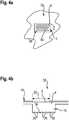
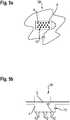
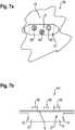
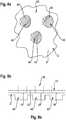
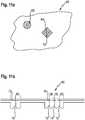
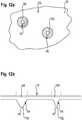
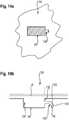
1a eine Draufsicht und1b eine Seitenansicht einer Anordnung gemäß einem ersten Ausführungsbeispiel,2a eine Draufsicht und2b eine Seitenansicht einer Anordnung gemäß einem weiteren Ausführungsbeispiel,3a eine Draufsicht und3b eine Seitenansicht einer Anordnung gemäß einem weiteren Ausführungsbeispiel,4a eine Draufsicht und4b eine Seitenansicht einer Anordnung gemäß einem weiteren Ausführungsbeispiel,5a eine Draufsicht und5b eine Seitenansicht einer Anordnung gemäß einem weiteren Ausführungsbeispiel,6a eine Draufsicht und6b eine Seitenansicht einer Anordnung gemäß einem weiteren Ausführungsbeispiel,7a eine Draufsicht und7b eine Seitenansicht einer Anordnung gemäß einem weiteren Ausführungsbeispiel,8a eine Draufsicht und8b eine Seitenansicht einer Anordnung gemäß einem weiteren Ausführungsbeispiel,9a eine Draufsicht und9b eine Seitenansicht einer Anordnung gemäß einem weiteren Ausführungsbeispiel,10a eine Draufsicht und10b eine Seitenansicht einer Anordnung gemäß einem weiteren Ausführungsbeispiel,11a eine Draufsicht und11b eine Seitenansicht einer Anordnung gemäß einem weiteren Ausführungsbeispiel,12a eine Draufsicht und12b eine Seitenansicht einer Anordnung gemäß einem weiteren Ausführungsbeispiel,13a eine Draufsicht und13b eine Seitenansicht einer Anordnung gemäß einem weiteren Ausführungsbeispiel,14a eine Draufsicht und14b eine Seitenansicht einer Anordnung gemäß einem weiteren Ausführungsbeispiel, und15a eine Draufsicht und15b eine Seitenansicht einer Anordnung gemäß einem weiteren Ausführungsbeispiel.
1a a top view and1b a side view of an arrangement according to a first embodiment,2a a top view and2 B a side view of an arrangement according to a further embodiment,3a a top view and3b a side view of an arrangement according to a further embodiment,4a a top view and4b a side view of an arrangement according to a further embodiment,5a a top view and5b a side view of an arrangement according to a further embodiment,6a a top view and6b a side view of an arrangement according to a further embodiment,7a a top view and7b a side view of an arrangement according to a further embodiment,8a a top view and8b a side view of an arrangement according to a further embodiment,9a a top view and9b a side view of an arrangement according to a further embodiment,10a a top view and10b a side view of an arrangement according to a further embodiment,11a a top view and11b a side view of an arrangement according to a further embodiment,12a a top view and12b a side view of an arrangement according to a further embodiment,13a a top view and13b a side view of an arrangement according to a further embodiment,14a a top view and14b a side view of an arrangement according to a further embodiment, and15a a top view and15b a side view of an arrangement according to a further embodiment.
In
Das optische Element
In
In
Die Anordnung
In
In
In
Eine Anordnung
In
In
In
In
In
In
In
In
Das optische Element
In
In
In
In
Das optische Element
In
In dem Schnitt der Anordnung
In
In
BezugszeichenlisteList of reference symbols
- 1, 26, 28, 32, 38, 44, 54, 58, 62, 66, 80, 92, 106, 124, 1361, 26, 28, 32, 38, 44, 54, 58, 62, 66, 80, 92, 106, 124, 136
- Anordnungarrangement
- 22
- FahrzeugbauteilVehicle component
- 4, 27, 29, 46, 68, 70, 82, 94, 96, 108, 1104, 27, 29, 46, 68, 70, 82, 94, 96, 108, 110
- Optisches ElementOptical element
- 6, 48, 72, 74, 84, 98, 100, 112, 1146, 48, 72, 74, 84, 98, 100, 112, 114
- LichtauskoppelflächeLight output surface
- 88th
- AußenflächeExterior surface
- 10, 116, 118, 126, 13810, 116, 118, 126, 138
- EinkoppelstrukturCoupling structure
- 12, 30, 76, 78, 84, 90, 102, 104, 120, 122, 128, 14212, 30, 76, 78, 84, 90, 102, 104, 120, 122, 128, 142
- EinkoppelflächeCoupling surface
- 130, 144130, 144
- Übergangcrossing
- 1616
- LichtquelleLight source
- 1818th
- Lichtundurchlässige SchichtOpaque layer
- 20, 50, 56, 6020, 50, 56, 60
- Abschnittsection
- 22, 13222, 132
- ElementflächeElement area
- 24, 34, 40, 6424, 34, 40, 64
- AuskoppelstrukturflächeOutcoupling structure area
- 3131
- Fahrzeugvehicle
- 3636
- AuskoppelstrukturDecoupling structure
- 4242
- Bestreuenden BereicheSprinkling areas
- 5252
- MantelflächeOuter surface
- 116, 118116, 118
- TIR-KollimatorTIR collimator
- 126, 138126, 138
- EinkoppelstrukturCoupling structure
- 134, 140134, 140
- MantelflächeOuter surface
Claims (15)
Translated fromGermanApplications Claiming Priority (2)
| Application Number | Priority Date | Filing Date | Title |
|---|---|---|---|
| DE102020109846 | 2020-04-08 | ||
| DE102020109846.4 | 2020-04-08 |
Publications (1)
| Publication Number | Publication Date |
|---|---|
| DE102020116263A1true DE102020116263A1 (en) | 2021-10-14 |
Family
ID=77851650
Family Applications (2)
| Application Number | Title | Priority Date | Filing Date |
|---|---|---|---|
| DE102020116264.2APendingDE102020116264A1 (en) | 2020-04-08 | 2020-06-19 | LIGHT GUIDE DEVICE, VEHICLE COMPONENTS AND VEHICLE |
| DE102020116263.4APendingDE102020116263A1 (en) | 2020-04-08 | 2020-06-19 | ARRANGEMENT FOR A VEHICLE, VEHICLE LAMP AND VEHICLE |
Family Applications Before (1)
| Application Number | Title | Priority Date | Filing Date |
|---|---|---|---|
| DE102020116264.2APendingDE102020116264A1 (en) | 2020-04-08 | 2020-06-19 | LIGHT GUIDE DEVICE, VEHICLE COMPONENTS AND VEHICLE |
Country Status (1)
| Country | Link |
|---|---|
| DE (2) | DE102020116264A1 (en) |
Cited By (1)
| Publication number | Priority date | Publication date | Assignee | Title |
|---|---|---|---|---|
| DE102023128684A1 (en) | 2023-10-19 | 2025-04-24 | Daimler Truck AG | Lighting device, headlight device with such a lighting device and motor vehicle with such a lighting device |
Families Citing this family (1)
| Publication number | Priority date | Publication date | Assignee | Title |
|---|---|---|---|---|
| DE102023002900B3 (en) | 2023-07-17 | 2024-07-18 | Mercedes-Benz Group AG | Illuminated panel for a motor vehicle |
Citations (10)
| Publication number | Priority date | Publication date | Assignee | Title |
|---|---|---|---|---|
| DE4109532A1 (en) | 1990-03-30 | 1991-10-02 | Toyoda Gosei Kk | Illuminated trim panel for vehicle - has small light openings for integral lamp and with plane appearance when switched off |
| US20020101738A1 (en) | 2001-01-31 | 2002-08-01 | Misaras David M. | Backlighting method for an automotive trim panel |
| DE10102774A1 (en) | 2001-01-23 | 2002-08-14 | Bosch Gmbh Robert | Dashboard dial display for a motor vehicle has a light guide device behind a partially transparent display surface with limited areas of brightness enhancement film on the inner surface of the light guide to improve light yield |
| US6454422B1 (en) | 2000-10-26 | 2002-09-24 | Trw Inc. | Backlit indicia on a painted surface |
| EP1696404A1 (en) | 2005-02-25 | 2006-08-30 | Electrovac, Fabrikation elektrotechnischer Spezialartikel Gesellschaft m.b.H. | Light emitting diode assembly |
| DE202006018515U1 (en) | 2006-12-07 | 2007-02-08 | Albea Kunststofftechnik Gmbh | Decorative- and/or operator-element e.g. for automobile interior, has metallised foil joined to edges of opening of housing body |
| FR2937929A1 (en) | 2008-11-04 | 2010-05-07 | Faurecia Interieur Ind | Trim panel for motor vehicle, has light transmitting layer arranged against skin for illuminating pictogram forming zone, and fixation element at support layer for maintaining light transmitting layer in opening |
| DE102010030911A1 (en) | 2010-07-02 | 2012-01-05 | Kunststoff-Technik Scherer & Trier Gmbh & Co Kg | Process for producing a molded part and molded part |
| US20120033408A1 (en) | 2009-07-28 | 2012-02-09 | Sumitomo Wiring Systems, Ltd. | Design panel and method for producing the same |
| US20120327673A1 (en) | 2011-06-21 | 2012-12-27 | Grupo Antolin-Ingeniera, S.A. | Trim part for automobile with integrated lighting device and process for manufacturing it |
Family Cites Families (12)
| Publication number | Priority date | Publication date | Assignee | Title |
|---|---|---|---|---|
| DE19818009C2 (en) | 1998-04-22 | 2003-05-22 | Mcgavigan John Ltd | Multi-layer cover for multi-function rear lights for road vehicles |
| DE20019073U1 (en) | 2000-11-09 | 2001-02-22 | Hella KG Hueck & Co., 59557 Lippstadt | Lighting device |
| GB0215304D0 (en) | 2002-07-03 | 2002-08-14 | Delphi Tech Inc | Illuminated sign or device |
| WO2009074510A1 (en) | 2007-12-10 | 2009-06-18 | Volkswagen Ag | Vehicle lamp and method for producing a transparent element for a vehicle lamp |
| DE102008048751A1 (en) | 2008-09-25 | 2010-04-01 | Automotive Lighting Reutlingen Gmbh | Luminaire for motor vehicles |
| DE102009031820C5 (en) | 2009-07-03 | 2015-11-05 | Novem Car Interior Design Gmbh | Motor vehicle interior lining part with light guide |
| DE102010030660A1 (en) | 2010-06-29 | 2011-12-29 | Lisa Dräxlmaier GmbH | Illuminated vehicle interior part |
| DE102011016394A1 (en) | 2011-04-08 | 2012-10-11 | GM Global Technology Operations LLC (n. d. Gesetzen des Staates Delaware) | Pillar covering parts for use as functional devices for covering e.g. pillar in inner space of saloon car, has lighting device comprising light source and light conductor that forms undetachable, integral part of part |
| DE102011103200A1 (en) | 2011-05-31 | 2012-12-06 | SMR Patents S.à.r.l. | Light window for use as light conductor for turn indicator in outside mirror arrangement of vehicle, has uncoupling structures at certain location of window, and optical film with molded coating and provided with uncoupling structures |
| DE102011081864B4 (en) | 2011-08-31 | 2017-08-24 | Fa. Lisa Dräxlmaier | Molded part for forming a vehicle component |
| AT520399B1 (en) | 2017-08-29 | 2020-10-15 | Zkw Group Gmbh | LIGHTING DEVICE AND / OR SIGNALING DEVICE FOR A MOTOR VEHICLE |
| EP3575153A1 (en) | 2019-05-29 | 2019-12-04 | WEIDPLAS GmbH | Backlit component |
- 2020
- 2020-06-19DEDE102020116264.2Apatent/DE102020116264A1/enactivePending
- 2020-06-19DEDE102020116263.4Apatent/DE102020116263A1/enactivePending
Patent Citations (10)
| Publication number | Priority date | Publication date | Assignee | Title |
|---|---|---|---|---|
| DE4109532A1 (en) | 1990-03-30 | 1991-10-02 | Toyoda Gosei Kk | Illuminated trim panel for vehicle - has small light openings for integral lamp and with plane appearance when switched off |
| US6454422B1 (en) | 2000-10-26 | 2002-09-24 | Trw Inc. | Backlit indicia on a painted surface |
| DE10102774A1 (en) | 2001-01-23 | 2002-08-14 | Bosch Gmbh Robert | Dashboard dial display for a motor vehicle has a light guide device behind a partially transparent display surface with limited areas of brightness enhancement film on the inner surface of the light guide to improve light yield |
| US20020101738A1 (en) | 2001-01-31 | 2002-08-01 | Misaras David M. | Backlighting method for an automotive trim panel |
| EP1696404A1 (en) | 2005-02-25 | 2006-08-30 | Electrovac, Fabrikation elektrotechnischer Spezialartikel Gesellschaft m.b.H. | Light emitting diode assembly |
| DE202006018515U1 (en) | 2006-12-07 | 2007-02-08 | Albea Kunststofftechnik Gmbh | Decorative- and/or operator-element e.g. for automobile interior, has metallised foil joined to edges of opening of housing body |
| FR2937929A1 (en) | 2008-11-04 | 2010-05-07 | Faurecia Interieur Ind | Trim panel for motor vehicle, has light transmitting layer arranged against skin for illuminating pictogram forming zone, and fixation element at support layer for maintaining light transmitting layer in opening |
| US20120033408A1 (en) | 2009-07-28 | 2012-02-09 | Sumitomo Wiring Systems, Ltd. | Design panel and method for producing the same |
| DE102010030911A1 (en) | 2010-07-02 | 2012-01-05 | Kunststoff-Technik Scherer & Trier Gmbh & Co Kg | Process for producing a molded part and molded part |
| US20120327673A1 (en) | 2011-06-21 | 2012-12-27 | Grupo Antolin-Ingeniera, S.A. | Trim part for automobile with integrated lighting device and process for manufacturing it |
Cited By (1)
| Publication number | Priority date | Publication date | Assignee | Title |
|---|---|---|---|---|
| DE102023128684A1 (en) | 2023-10-19 | 2025-04-24 | Daimler Truck AG | Lighting device, headlight device with such a lighting device and motor vehicle with such a lighting device |
Also Published As
| Publication number | Publication date |
|---|---|
| DE102020116264A1 (en) | 2021-10-14 |
Similar Documents
| Publication | Publication Date | Title |
|---|---|---|
| DE102012107437B4 (en) | lighting device | |
| DE102016119326A1 (en) | Lighting device for a vehicle | |
| DE102010006348A1 (en) | Illumination device for car, has two light units comprising two planar light guide elements, respectively, where back sides and/or front sides of guide elements are provided with same uncoupling element | |
| DE102017120532A1 (en) | Lighting device for a vehicle, in particular electric vehicle | |
| AT517394B1 (en) | Lighting device for a motor vehicle with luminescent elements | |
| WO2008080475A1 (en) | Vehicle light | |
| EP3355664A1 (en) | Illuminant with fluorescent element and colour filter and light equipped with same | |
| DE102018214790A1 (en) | Lighting device for a motor vehicle | |
| DE102020116263A1 (en) | ARRANGEMENT FOR A VEHICLE, VEHICLE LAMP AND VEHICLE | |
| DE102016205408A1 (en) | Luminaire for a motor vehicle | |
| DE102005019018A1 (en) | Motor vehicle lamp, has optical waveguide with mutually spaced light entry surfaces | |
| DE102010032946A1 (en) | Motor car has upper light source and lower light source comprising flat organic LED, where upper light source is arranged transverse to main emission direction | |
| DE102007033706A1 (en) | Vehicle lighting device consists of lighting device that has housing with chamber in which light source is located with colour changing light disc | |
| DE102012007227A1 (en) | Lighting device for vehicle lamp, has optical element having coupling point for coupling light beams emitted from light sources and decoupling point for coupling light beams | |
| DE102014104891A1 (en) | License plate lighting device with multiple layers | |
| DE102016114246A1 (en) | Signal light for vehicles | |
| EP3792111B1 (en) | Lamp | |
| DE102011104055A1 (en) | Illumination device, particularly headlight or rear light for vehicle, comprises light source, which has multiple semiconductor light sources, where reflector has reflector body and reflection surface | |
| EP3814172B1 (en) | Method for producing a blinker module, blinker module, rear-view device, and motor vehicle | |
| WO2021204687A1 (en) | Assembly and vehicle | |
| EP4067732A1 (en) | Vehicle light with a luminous surface comprising a reflector surface | |
| EP2146138A1 (en) | Lamp | |
| DE102007033709A1 (en) | Vehicle lighting device i.e. tail lamp, for integrated installation in corner marginal area of motor vehicle i.e. passenger car, has disk integrated with optical units having cylindrical part with pre-settable height and mold surface part | |
| DE102013211780A1 (en) | LICENSE PLATE LIGHTING DEVICE | |
| DE102020201645A1 (en) | Lighting device for a motor vehicle |
Legal Events
| Date | Code | Title | Description |
|---|---|---|---|
| R012 | Request for examination validly filed | ||
| R016 | Response to examination communication | ||
| R016 | Response to examination communication | ||
| R016 | Response to examination communication | ||
| R016 | Response to examination communication |