DE102020115415A1 - Coupling device for connecting high-voltage connections - Google Patents
Coupling device for connecting high-voltage connectionsDownload PDFInfo
- Publication number
- DE102020115415A1 DE102020115415A1DE102020115415.1ADE102020115415ADE102020115415A1DE 102020115415 A1DE102020115415 A1DE 102020115415A1DE 102020115415 ADE102020115415 ADE 102020115415ADE 102020115415 A1DE102020115415 A1DE 102020115415A1
- Authority
- DE
- Germany
- Prior art keywords
- cover element
- coupling device
- connection
- state
- pressure pin
- Prior art date
- Legal status (The legal status is an assumption and is not a legal conclusion. Google has not performed a legal analysis and makes no representation as to the accuracy of the status listed.)
- Pending
Links
- 230000008878couplingEffects0.000titleclaimsabstractdescription33
- 238000010168coupling processMethods0.000titleclaimsabstractdescription33
- 238000005859coupling reactionMethods0.000titleclaimsabstractdescription33
- 230000007246mechanismEffects0.000claimsdescription9
- 230000008859changeEffects0.000description9
- 230000007613environmental effectEffects0.000description7
- 238000011109contaminationMethods0.000description4
- 238000000034methodMethods0.000description4
- 244000059549Borneo rubberSpecies0.000description3
- 238000004146energy storageMethods0.000description3
- 239000000463materialSubstances0.000description3
- 230000008569processEffects0.000description3
- 238000011161developmentMethods0.000description2
- 230000018109developmental processEffects0.000description2
- 238000006073displacement reactionMethods0.000description2
- 239000000428dustSubstances0.000description2
- 238000009434installationMethods0.000description2
- 238000004519manufacturing processMethods0.000description2
- 239000007769metal materialSubstances0.000description2
- 239000002245particleSubstances0.000description2
- 230000008439repair processEffects0.000description2
- XLYOFNOQVPJJNP-UHFFFAOYSA-NwaterSubstancesOXLYOFNOQVPJJNP-UHFFFAOYSA-N0.000description2
- BUHVIAUBTBOHAG-FOYDDCNASA-N(2r,3r,4s,5r)-2-[6-[[2-(3,5-dimethoxyphenyl)-2-(2-methylphenyl)ethyl]amino]purin-9-yl]-5-(hydroxymethyl)oxolane-3,4-diolChemical compoundCOC1=CC(OC)=CC(C(CNC=2C=3N=CN(C=3N=CN=2)[C@H]2[C@@H]([C@H](O)[C@@H](CO)O2)O)C=2C(=CC=CC=2)C)=C1BUHVIAUBTBOHAG-FOYDDCNASA-N0.000description1
- 230000001419dependent effectEffects0.000description1
- 230000000694effectsEffects0.000description1
- 230000005489elastic deformationEffects0.000description1
- 239000013013elastic materialSubstances0.000description1
- 230000010354integrationEffects0.000description1
- 238000012423maintenanceMethods0.000description1
- 230000007257malfunctionEffects0.000description1
- 239000002184metalSubstances0.000description1
Images


Classifications
- H—ELECTRICITY
- H01—ELECTRIC ELEMENTS
- H01R—ELECTRICALLY-CONDUCTIVE CONNECTIONS; STRUCTURAL ASSOCIATIONS OF A PLURALITY OF MUTUALLY-INSULATED ELECTRICAL CONNECTING ELEMENTS; COUPLING DEVICES; CURRENT COLLECTORS
- H01R13/00—Details of coupling devices of the kinds covered by groups H01R12/70 or H01R24/00 - H01R33/00
- H01R13/46—Bases; Cases
- H01R13/53—Bases or cases for heavy duty; Bases or cases for high voltage with means for preventing corona or arcing
- B—PERFORMING OPERATIONS; TRANSPORTING
- B60—VEHICLES IN GENERAL
- B60L—PROPULSION OF ELECTRICALLY-PROPELLED VEHICLES; SUPPLYING ELECTRIC POWER FOR AUXILIARY EQUIPMENT OF ELECTRICALLY-PROPELLED VEHICLES; ELECTRODYNAMIC BRAKE SYSTEMS FOR VEHICLES IN GENERAL; MAGNETIC SUSPENSION OR LEVITATION FOR VEHICLES; MONITORING OPERATING VARIABLES OF ELECTRICALLY-PROPELLED VEHICLES; ELECTRIC SAFETY DEVICES FOR ELECTRICALLY-PROPELLED VEHICLES
- B60L53/00—Methods of charging batteries, specially adapted for electric vehicles; Charging stations or on-board charging equipment therefor; Exchange of energy storage elements in electric vehicles
- B60L53/10—Methods of charging batteries, specially adapted for electric vehicles; Charging stations or on-board charging equipment therefor; Exchange of energy storage elements in electric vehicles characterised by the energy transfer between the charging station and the vehicle
- B60L53/14—Conductive energy transfer
- B60L53/16—Connectors, e.g. plugs or sockets, specially adapted for charging electric vehicles
- H—ELECTRICITY
- H01—ELECTRIC ELEMENTS
- H01R—ELECTRICALLY-CONDUCTIVE CONNECTIONS; STRUCTURAL ASSOCIATIONS OF A PLURALITY OF MUTUALLY-INSULATED ELECTRICAL CONNECTING ELEMENTS; COUPLING DEVICES; CURRENT COLLECTORS
- H01R13/00—Details of coupling devices of the kinds covered by groups H01R12/70 or H01R24/00 - H01R33/00
- H01R13/62—Means for facilitating engagement or disengagement of coupling parts or for holding them in engagement
- H01R13/629—Additional means for facilitating engagement or disengagement of coupling parts, e.g. aligning or guiding means, levers, gas pressure electrical locking indicators, manufacturing tolerances
- H01R13/633—Additional means for facilitating engagement or disengagement of coupling parts, e.g. aligning or guiding means, levers, gas pressure electrical locking indicators, manufacturing tolerances for disengagement only
- H01R13/635—Additional means for facilitating engagement or disengagement of coupling parts, e.g. aligning or guiding means, levers, gas pressure electrical locking indicators, manufacturing tolerances for disengagement only by mechanical pressure, e.g. spring force
- H—ELECTRICITY
- H01—ELECTRIC ELEMENTS
- H01R—ELECTRICALLY-CONDUCTIVE CONNECTIONS; STRUCTURAL ASSOCIATIONS OF A PLURALITY OF MUTUALLY-INSULATED ELECTRICAL CONNECTING ELEMENTS; COUPLING DEVICES; CURRENT COLLECTORS
- H01R2201/00—Connectors or connections adapted for particular applications
- H01R2201/26—Connectors or connections adapted for particular applications for vehicles
- Y—GENERAL TAGGING OF NEW TECHNOLOGICAL DEVELOPMENTS; GENERAL TAGGING OF CROSS-SECTIONAL TECHNOLOGIES SPANNING OVER SEVERAL SECTIONS OF THE IPC; TECHNICAL SUBJECTS COVERED BY FORMER USPC CROSS-REFERENCE ART COLLECTIONS [XRACs] AND DIGESTS
- Y02—TECHNOLOGIES OR APPLICATIONS FOR MITIGATION OR ADAPTATION AGAINST CLIMATE CHANGE
- Y02E—REDUCTION OF GREENHOUSE GAS [GHG] EMISSIONS, RELATED TO ENERGY GENERATION, TRANSMISSION OR DISTRIBUTION
- Y02E60/00—Enabling technologies; Technologies with a potential or indirect contribution to GHG emissions mitigation
- Y02E60/10—Energy storage using batteries
- Y—GENERAL TAGGING OF NEW TECHNOLOGICAL DEVELOPMENTS; GENERAL TAGGING OF CROSS-SECTIONAL TECHNOLOGIES SPANNING OVER SEVERAL SECTIONS OF THE IPC; TECHNICAL SUBJECTS COVERED BY FORMER USPC CROSS-REFERENCE ART COLLECTIONS [XRACs] AND DIGESTS
- Y02—TECHNOLOGIES OR APPLICATIONS FOR MITIGATION OR ADAPTATION AGAINST CLIMATE CHANGE
- Y02T—CLIMATE CHANGE MITIGATION TECHNOLOGIES RELATED TO TRANSPORTATION
- Y02T10/00—Road transport of goods or passengers
- Y02T10/60—Other road transportation technologies with climate change mitigation effect
- Y02T10/70—Energy storage systems for electromobility, e.g. batteries
- Y—GENERAL TAGGING OF NEW TECHNOLOGICAL DEVELOPMENTS; GENERAL TAGGING OF CROSS-SECTIONAL TECHNOLOGIES SPANNING OVER SEVERAL SECTIONS OF THE IPC; TECHNICAL SUBJECTS COVERED BY FORMER USPC CROSS-REFERENCE ART COLLECTIONS [XRACs] AND DIGESTS
- Y02—TECHNOLOGIES OR APPLICATIONS FOR MITIGATION OR ADAPTATION AGAINST CLIMATE CHANGE
- Y02T—CLIMATE CHANGE MITIGATION TECHNOLOGIES RELATED TO TRANSPORTATION
- Y02T10/00—Road transport of goods or passengers
- Y02T10/60—Other road transportation technologies with climate change mitigation effect
- Y02T10/7072—Electromobility specific charging systems or methods for batteries, ultracapacitors, supercapacitors or double-layer capacitors
- Y—GENERAL TAGGING OF NEW TECHNOLOGICAL DEVELOPMENTS; GENERAL TAGGING OF CROSS-SECTIONAL TECHNOLOGIES SPANNING OVER SEVERAL SECTIONS OF THE IPC; TECHNICAL SUBJECTS COVERED BY FORMER USPC CROSS-REFERENCE ART COLLECTIONS [XRACs] AND DIGESTS
- Y02—TECHNOLOGIES OR APPLICATIONS FOR MITIGATION OR ADAPTATION AGAINST CLIMATE CHANGE
- Y02T—CLIMATE CHANGE MITIGATION TECHNOLOGIES RELATED TO TRANSPORTATION
- Y02T90/00—Enabling technologies or technologies with a potential or indirect contribution to GHG emissions mitigation
- Y02T90/10—Technologies relating to charging of electric vehicles
- Y02T90/14—Plug-in electric vehicles
Landscapes
- Engineering & Computer Science (AREA)
- Power Engineering (AREA)
- Transportation (AREA)
- Mechanical Engineering (AREA)
- Battery Mounting, Suspending (AREA)
Abstract
Translated fromGerman
Description
Translated fromGermanDie Erfindung betrifft eine Kopplungsvorrichtung zur Verbindung von Hochvolt-Anschlüssen. Die Hochvolt-Anschlüsse sind insbesondere an einer Batterie oder an einem Kraftfahrzeug angeordnet. Das Kraftfahrzeug ist insbesondere ein elektrisch angetriebenes Kraftfahrzeug. Das Kraftfahrzeug weist insbesondere mindestens einen Traktionsantrieb auf, der über die Batterie mit elektrischer Energie versorgt wird.The invention relates to a coupling device for connecting high-voltage connections. The high-voltage connections are arranged in particular on a battery or on a motor vehicle. The motor vehicle is in particular an electrically driven motor vehicle. In particular, the motor vehicle has at least one traction drive that is supplied with electrical energy via the battery.
Kraftfahrzeuge mit einem elektrischem Antriebsstrang, also mit einem (elektrischen) Traktionsantrieb, weisen ein Batteriesystem als elektrischen Energiespeicher auf. Es ist bekannt, die Batterie über einen Hochvolt-Anschluss an das Hochvolt-Netz im Kraftfahrzeug anzuschließen. Soll die Batterie im Rahmen eines Wechselkonzepts z. B. vollautomatisiert ausgetauscht werden, ist eine einfache mechanische Anbindung der Batterie sowie eine automatisiert herstellbare elektrisch leitende Verbindung der Hochvolt-Anschlüsse von Kraftfahrzeug und Batterie erforderlich. Gerade während des Handlings der Batterie sind die Hochvolt-Anschlüsse insbesondere der Batterie vor Verschmutzung zu schützen. Bei Systemen und Bauteilen, die in Kraftfahrzeugen oberhalb 25 Volt oder sogar oberhalb 30 Volt Wechselspannung (AC) bzw. mindestens 60 Volt Gleichspannung (DC) betrieben werden, spricht man von Hochvolt-Systemen - folglich werden elektrische Anschlüsse für solche Anwendungen als Hochvolt-Anschlüsse bezeichnet.Motor vehicles with an electric drive train, that is to say with an (electric) traction drive, have a battery system as an electrical energy store. It is known to connect the battery to the high-voltage network in the motor vehicle via a high-voltage connection. Should the battery as part of a change concept z. B. be exchanged fully automatically, a simple mechanical connection of the battery and an automatically produced electrically conductive connection of the high-voltage connections of the motor vehicle and battery is required. The high-voltage connections, especially those of the battery, must be protected from contamination, especially when handling the battery. Systems and components that are operated in motor vehicles above 25 volts or even above 30 volts alternating voltage (AC) or at least 60 volts direct voltage (DC) are referred to as high-voltage systems - consequently, electrical connections for such applications are used as high-voltage connections designated.
Ziel bei einer Hochvolt-Batteriegehäuseentwicklung ist es, das Volumen für die Batteriezellen so groß wie möglich und das Gehäuse so klein wie möglich zu konstruieren, wobei sämtliche mechanischen Lastfälle ohne Brand und ohne Kurzschluss ertragen werden müssen. Um die maximale Leistungs- und Energiedichte zu erreichen, müssen Strukturbauteile platzsparend und möglichst ohne Redundanzen ausgelegt werden. Gleichzeitig muss neben dem Bauraum für die Zellen ausreichend Bauraum innerhalb des Gehäuses für die elektrischen Leitungen und Steuergeräte vorgehalten werden.The aim of a high-voltage battery housing development is to make the volume for the battery cells as large as possible and the housing as small as possible, whereby all mechanical load cases must be endured without fire and without short circuits. In order to achieve the maximum power and energy density, structural components must be designed to save space and, if possible, without redundancies. At the same time, in addition to the installation space for the cells, sufficient installation space must be kept within the housing for the electrical lines and control devices.
Im Zuge zukünftiger Mobilitätskonzepte gewinnt ein schneller, automatisierter Wechsel von Batteriemodulen und/oder Batterieeinheiten immer mehr an Bedeutung. Hier werden die Grenzen der vorhandenen - meist händischen - Möglichkeiten erreicht bzw. überschritten.In the course of future mobility concepts, a quick, automated change of battery modules and / or battery units is becoming more and more important. Here the limits of the existing - mostly manual - possibilities are reached or exceeded.
Gegenwärtig werden für Hochvolt-Batteriesysteme meist (sehr) große Batteriegehäuse eingesetzt. Der Austausch dieser Batteriesysteme und/oder Teile davon ist im Allgemeinen nicht vorgesehen bzw. findet nur bei Reparaturen statt. Die lasttragenden Batteriemodule bzw. SBUs (Smart Batterie Units) bieten die Möglichkeit eines planmäßigen Austauschs - beispielsweise zur Reichweitenanpassung. Allen Systemen gemein ist jedoch, dass der Wechsel zumindest teilweise händisch und mit hohem zeitlichen Aufwand stattfinden muss.At present, (very) large battery housings are mostly used for high-voltage battery systems. The replacement of these battery systems and / or parts thereof is generally not intended or only takes place during repairs. The load-bearing battery modules or SBUs (Smart Battery Units) offer the option of scheduled replacement - for example to adjust the range. What all systems have in common, however, is that the change must take place at least partially manually and with a high expenditure of time.
Große Batteriegehäuse sind insbesondere schwer und unhandlich. Eine Einzelentnahme von Batteriemodulen z. B. zu Zwecken des Kundendienstes oder für kundenseitige Reichweitenanpassungen ist damit nicht möglich; es muss stets mit hohem Aufwand das gesamte Batteriegehäuse demontiert und wieder montiert werden. Gleichzeitig ist eine aufwändigere und damit teurere Logistik und Produktion erforderlich.Large battery cases, in particular, are heavy and unwieldy. A single removal of battery modules z. B. for the purposes of customer service or for customer-side range adjustments is not possible; the entire battery housing must always be dismantled and reassembled with great effort. At the same time, more complex and therefore more expensive logistics and production are required.
Wie bereits dargestellt, ist der Wechsel bei den derzeitigen Systemen nur mit personellem Zusatzaufwand, d. h. zu signifikant hohen Kosten, möglich und/oder die erforderlichen Hardwarekomponenten sind komplex und bauraumintensiv, da sie keine konsequente Funktionsintegration verfolgen, und/oder für (sehr) große, nicht-gegliederte Batteriesysteme ausgelegt sind. Dadurch entstehen zusätzlich hohe Betriebs- und Wartungskosten sowie eine verlängerte Austauschdauer, die für einen Einsatz in Mobilitätskonzepten untauglich ist.As already shown, the change in the current systems is only possible with additional personnel, i.e. H. at significantly high costs, possible and / or the required hardware components are complex and space-intensive, since they do not pursue a consequent functional integration and / or are designed for (very) large, non-structured battery systems. This also results in high operating and maintenance costs as well as a longer replacement time, which is unsuitable for use in mobility concepts.
Ohne lasttragende Funktion der Batteriemodule kann ein, insbesondere vollautomatischer, Wechsel zu einem Sicherheitsrisiko werden, falls eine Fehlfunktion (z. B. Abrutschen und Herunterfallen, Anstoßen) in der Wechselstation auftritt. Darüber hinaus ist es im Havariefall (z. B. Unfall) den Rettungskräften nicht möglich, das Batteriesystem bzw. Batteriemodule schnell aus dem Fahrzeug zu lösen und vom Fahrzeug zu entfernen.Without the load-bearing function of the battery modules, a particularly fully automatic change can become a safety risk if a malfunction (e.g. slipping and falling, bumping) occurs in the changing station. In addition, in the event of an accident (e.g. accident), the rescue workers are unable to quickly detach the battery system or battery modules from the vehicle and remove them from the vehicle.
Es sind bislang keine Lösungen bekannt, die auf ein (sehr) großes Batteriegehäuse verzichten und einzelne insbesondere lasttragende Batteriemodule im Fahrzeug einsetzen sowie eine vollautomatische Wechselbarkeit dieser Batteriemodule ermöglichen.So far, no solutions are known that do without a (very) large battery housing and use individual, in particular load-bearing, battery modules in the vehicle and enable these battery modules to be exchanged fully automatically.
Die
Aus der
Aufgabe der vorliegenden Erfindung ist es, die mit Bezug auf den Stand der Technik angeführten Probleme zumindest teilweise zu lösen. Insbesondere soll eine Kopplungsvorrichtung zur Verbindung von Hochvolt-Anschlüssen, z. B. der Anschlüsse einer Batterie und eines Kraftfahrzeuges, vorgeschlagen werden, wobei die Kopplungsvorrichtung insbesondere auch ein vollautomatisches Wechseln der Batterie ermöglichen soll.It is the object of the present invention to at least partially solve the problems cited with reference to the prior art. In particular, a coupling device for connecting high-voltage connections, eg. B. the connections of a battery and a motor vehicle, be proposed, wherein the coupling device should in particular also enable fully automatic changing of the battery.
Zur Lösung dieser Aufgaben trägt eine Kopplungsvorrichtung mit den Merkmalen gemäß Patentanspruch 1 bei. Vorteilhafte Weiterbildungen sind Gegenstand der abhängigen Patentansprüche. Die in den Patentansprüchen einzeln aufgeführten Merkmale sind in technologisch sinnvoller Weise miteinander kombinierbar und können durch erläuternde Sachverhalte aus der Beschreibung und/oder Details aus den Figuren ergänzt werden, wobei weitere Ausführungsvarianten der Erfindung aufgezeigt werden.A coupling device with the features according to
Es wird eine Kopplungsvorrichtung zur Verbindung von Hochvolt-Anschlüssen vorgeschlagen. Die Kopplungsvorrichtung umfasst zumindest ein erstes Teil, das einen ersten Anschluss und einen Druckstift aufweist, sowie ein relativ zum ersten Teil bewegbares zweites Teil, dass einen mit dem ersten Anschluss verbindbaren zweiten Anschluss und eine Aufnahme für den Druckstift aufweist. In einem ersten Zustand, (also) bei getrennter Anordnung der Teile, ist zumindest der zweite Anschluss von einem Deckelelement gegenüber einer Umgebung abgedeckt bzw. abdeckbar. Zur Verbindung der Anschlüsse kann der Druckstift das Deckelelement betätigen und dabei (selber) in die Aufnahme eintauchen. Dabei kann das Deckelelement den zweiten Anschluss freigeben.A coupling device for connecting high-voltage connections is proposed. The coupling device comprises at least a first part, which has a first connection and a pressure pin, as well as a second part which is movable relative to the first part and which has a second connection that can be connected to the first connection and a receptacle for the pressure pin. In a first state, (that is to say) when the parts are arranged separately, at least the second connection is covered or can be covered by a cover element with respect to the surroundings. To connect the connections, the pressure pin can actuate the cover element and, in doing so, dip (itself) into the receptacle. The cover element can release the second connection.
Die Kopplungsvorrichtung ist insbesondere ein System zum Schutz der Hochvolt-Anschlüsse gegen Umwelteinflüsse bei Batteriewechselsystemen. Die Kopplungsvorrichtung wird am Beispiel von (automatischen) Batteriewechselsystemen erläutert bzw. beschrieben. Dabei kann sie aber auch grundsätzlich überall dort eingesetzt werden, wo ausgewählte Bereiche verschlossen werden sollen/müssen und der Verschluss (voll-)automatisch geöffnet und geschlossen werden soll.The coupling device is in particular a system for protecting the high-voltage connections against environmental influences in battery changing systems. The coupling device is explained and described using the example of (automatic) battery changing systems. In principle, it can also be used wherever selected areas should / must be closed and the closure should be (fully) automatically opened and closed.
Die Kopplungsvorrichtung dient insbesondere zum Schutz des zweiten Hochvolt-Anschlusses gegen Umwelteinflüsse bei Batteriewechselsystemen. Insbesondere wird so, gerade beim vollautomatischem Batteriewechsel, eine Dichtigkeit des Batteriesystems, welches insbesondere an einer Unterseite eines Kraftfahrzeugs angeordnet und damit allen Umgebungseinflüssen ausgesetzt ist, sichergestellt. Wechselbare Batterien und/oder Batteriemodule stellen insbesondere in sich abgeschlossene und dichte Einzelkomponenten dar und werden abgedichtet untereinander und mit einem Batterie Management System verbunden. Die einzige für Verschmutzung „offene“ Stelle des Batteriesystems ist demnach insbesondere der Hochvoltanschluss zum Kraftfahrzeug bzw. der fahrzeugseitige Hochvolt-Anschluss oder der Hochvolt-Anschluss zur Batterie. Sowohl der fahrzeugseitige, als auch der batterieseitige Hochvolt-Anschluss können als zweiter Anschluss abgedichtet ausgeführt werden, so dass auch im nicht verbundenen Zustand der Hochvoltanschlüsse ein dichtes System zumindest für das zweite Teil vorliegt.The coupling device serves in particular to protect the second high-voltage connection against environmental influences in battery exchange systems. In particular, this ensures that the battery system, which is arranged in particular on the underside of a motor vehicle and is therefore exposed to all environmental influences, is sealed, especially during fully automatic battery changes. Exchangeable batteries and / or battery modules represent, in particular, self-contained and sealed individual components and are sealed to one another and connected to a battery management system. The only “open” point in the battery system for contamination is accordingly in particular the high-voltage connection to the motor vehicle or the high-voltage connection on the vehicle or the high-voltage connection to the battery. Both the vehicle-side and the battery-side high-voltage connection can be designed as a second connection in a sealed manner, so that a tight system is present at least for the second part even when the high-voltage connections are not connected.
In einem ungesteckten bzw. entkoppelten Zustand der Hochvolt-Anschlüsse können insbesondere die beteiligten Steckungspartner (Stecker und Buchse; hier erstes Teil und zweites Teil bzw. erster Anschluss und zweiter Anschluss) von Umwelteinflüssen erreicht werden. In festverbauten Batteriesystemen erfolgt die Steckung manuell während der Montage und Demontage, z. B. bei der Produktion oder bei Reparaturen. Dies findet im Regelfall nur sehr selten statt und unter Bedingungen, bei denen die Umwelteinflüsse bzw. deren Auswirkungen kontrolliert bzw. überwacht werden können und den Folgen begegnet werden kann. Bei einem regelmäßigen vollautomatischen Batteriewechsel finden einerseits naturgemäß deutlich mehr Wechsel statt und andererseits sollen diese Wechsel möglichst schnell und mit möglichst wenigen Prozessschritten erfolgen. Dies führt dazu, dass die Umwelteinflüsse während des Wechsels stärkere Bedeutung erhalten.In an unplugged or decoupled state of the high-voltage connections, in particular the connection partners involved (plug and socket; here first part and second part or first connection and second connection) can be reached by environmental influences. In permanently installed battery systems, the connection is made manually during assembly and disassembly, e.g. B. in production or repairs. As a rule, this only takes place very rarely and under conditions in which the environmental influences or their effects can be controlled or monitored and the consequences can be countered. With a regular, fully automatic battery change, on the one hand, of course, significantly more changes take place and, on the other hand, these changes should be made as quickly as possible and with as few process steps as possible. This means that the environmental influences become more important during the change.
Bei einem entsprechenden Wechsel kann auftreten, dass sich Schmutz, Wasser, Schnee, usw. vom Kraftfahrzeug löst und mit dem sich gerade im An-/Abtransport befindlichen Batteriesystem in Kontakt kommt. Sollte dies im Bereich des Hochvolt-Anschlusses geschehen, so kann sich daraus ein Sicherheitsrisiko ergeben, beispielsweise wenn durch Wasser eine Verbindung zwischen den beiden Polen des Hochvolt-Anschlusses hergestellt wird, was zu einem Kurzschluss führen würde.With a corresponding change, it can happen that dirt, water, snow, etc. come loose from the motor vehicle and come into contact with the battery system that is currently being transported to / from the vehicle. If this happens in the area of the high-voltage connection, this can result in a safety risk, for example if a connection is established between the two poles of the high-voltage connection through water, which would lead to a short circuit.
Vorliegend wird daher eine Kopplungsvorrichtung vorgestellt, die insbesondere den batterieseitigen und/ oder fahrzeugseitigen Hochvolt-Anschluss vor Umwelteinflüssen schützt.In the present case, a coupling device is therefore presented which in particular protects the battery-side and / or vehicle-side high-voltage connection from environmental influences.
Der (erste und zweite) Anschluss umfasst insbesondere mehrere elektrische Kontakte, die mit elektrischen Kontakten eines weiteren (zweiten oder ersten) Anschlusses verbindbar sind. Der Anschluss, bzw. dessen Kontakte, kann von einer Umgebung durch das Deckelelement getrennt und damit vor Verschmutzungen geschützt werden.The (first and second) connection comprises in particular a plurality of electrical contacts which can be connected to electrical contacts of a further (second or first) connection. The connection or its contacts can be separated from the environment by the cover element and thus protected from contamination.
In einem ersten Zustand sind die Teile der Kopplungsvorrichtung insbesondere beabstandet voneinander angeordnet, so dass die Teile einander nicht kontaktieren. Z. B. ist das erste Teil an einem Kraftfahrzeug und das zweite Teil an einer Batterie angeordnet, wobei die Batterie (noch) nicht an dem Kraftfahrzeug angeordnet ist.In a first state, the parts of the coupling device are in particular arranged at a distance from one another, so that the parts do not contact one another. For example, the first part is arranged on a motor vehicle and the second part is arranged on a battery, the battery not (yet) being arranged on the motor vehicle.
In dem ersten Zustand ist zumindest der zweite Anschluss, ggf. auch die Aufnahme, von dem Deckelelement gegenüber der Umgebung abgedeckt, so dass eine Verschmutzung dieser Komponenten aus der Umgebung, z. B. durch Staubpartikel oder Feuchtigkeit, zumindest teilweise verhindert wird.At least the second connection, possibly also the receptacle, is in the first state Cover element covered with respect to the environment, so that contamination of these components from the environment, z. B. by dust particles or moisture, is at least partially prevented.
Sollen die Teile miteinander verbunden werden, so werden sie aufeinander zu bewegt. Dabei kontaktiert, insbesondere als erstes, der Druckstift das Deckelelement. Bei weiterer Annährung der Teile, wird das Deckelelement durch den Druckstift betätigt und aus einer im ersten Zustand vorliegenden Ausgangsstellung sukzessive verlagert bzw. verschoben. Insbesondere taucht dabei der Druckstift in die Aufnahme ein.If the parts are to be connected to one another, they are moved towards one another. In this case, the pressure pin contacts the cover element, in particular first. As the parts come closer together, the cover element is actuated by the pressure pin and gradually displaced or displaced from an initial position in the first state. In particular, the pressure pin dips into the receptacle.
Insbesondere wird der Druckstift durch die Aufnahme geführt, so dass eine Ausrichtung der Teile zueinander erfolgt. Diese Ausrichtung ermöglicht bzw. erleichtert die Verbindung der Anschlüsse.In particular, the pressure pin is guided through the receptacle so that the parts are aligned with one another. This alignment enables or facilitates the connection of the connections.
Die Aufnahme bildet insbesondere eine Hülse, in die der Druckstift eingeführt werden kann. Die Form der Hülse ist insbesondere an die Form des Druckstiftes angepasst, so dass über die Aufnahme die Ausrichtung des Druckstiftes und damit des ersten Teils gegenüber dem zweiten Teil erfolgen kann.The receptacle forms in particular a sleeve into which the pressure pin can be inserted. The shape of the sleeve is adapted in particular to the shape of the pressure pin, so that the pressure pin and thus the first part can be aligned with respect to the second part via the receptacle.
Insbesondere ist in dem ersten Zustand (auch) die Aufnahme von dem Deckelelement abgedeckt.In particular, in the first state, the receptacle is (also) covered by the cover element.
Insbesondere ist das Deckelelement durch den Druckstift zumindest teilweise in die Aufnahme hinein verschiebbar ist.In particular, the cover element can be at least partially displaced into the receptacle by the pressure pin.
Insbesondere sind die Teile ausgehend von dem ersten Zustand und hin zu einem zweiten Zustand, in dem die Teile zumindest über die Anschlüsse miteinander verbunden sind, entlang einer ersten Richtung aufeinander zu bewegbar, wobei das Deckelement durch den Druckstift zumindest entlang einer quer zur ersten Richtung verlaufenden zweiten Richtung verschiebbar ist.In particular, starting from the first state and moving towards a second state in which the parts are connected to one another at least via the connections, the parts can be moved towards one another along a first direction, the cover element being at least transverse to the first direction through the pressure pin second direction is displaceable.
Bevorzugt wird ein zweiter Abschnitt des Deckelelements zusammen mit dem Druckstift in die Aufnahme hinein verschoben. Dabei wird dieser zweite Abschnitt entlang der ersten Richtung in die Aufnahme hinein verlagert.A second section of the cover element is preferably moved into the receptacle together with the pressure pin. This second section is displaced into the receptacle along the first direction.
Insbesondere wird (zusätzlich) ein erster Abschnitt des Deckelelements entlang der zweiten Richtung hin zur Aufnahme verschoben.In particular, a first section of the cover element is (additionally) displaced along the second direction towards the receptacle.
Insbesondere wird mit weiterer Annährung der Teile zueinander der Anteil des zweiten Abschnitts am Deckelelement größer und der Anteil des ersten Abschnitts am Deckelelement kleiner, da ein immer größerer Anteil des Deckelelements in die Aufnahme hinein verlagert wird.In particular, as the parts come closer to one another, the proportion of the second section on the cover element increases and the proportion of the first section on the cover element becomes smaller, since an ever larger proportion of the cover element is displaced into the receptacle.
Insbesondere erstreckt sich das Deckelelement in dem ersten Zustand ausgehend von einem ersten Ende über den zweiten Anschluss und die Aufnahme bis hin zum einem zweiten Ende. Das erste Ende ist insbesondere beweglich gegenüber dem zweiten Teil angeordnet. Das zweite Ende ist insbesondere ortsfest an dem zweiten Teil angeordnet.In particular, in the first state, the cover element extends from a first end over the second connection and the receptacle to a second end. The first end is in particular arranged to be movable with respect to the second part. The second end is in particular arranged in a stationary manner on the second part.
Der erste Abschnitt erstreckt sich ausgehend von dem ersten Ende hin zum zweiten Ende.The first section extends from the first end to the second end.
Alternativ wird das Deckelelement so betätigt, z. B. über das zweite Ende, dass das zweite Ende von dem Druckstift in die Aufnahme hinein verlagert wird.Alternatively, the cover element is operated such. B. via the second end that the second end is displaced from the pressure pin into the receptacle.
Wenn der Druckstift in die Aufnahme hinein verschoben wird, kontaktiert er das sich über die Aufnahme erstreckende Deckelelement und verformt dieses oder kontaktiert das Deckelelement z. B. im Bereich des zweiten Endes. In beiden Fällen wird das Deckelelement zumindest teilweise in die Aufnahme hinein verschoben, so dass das erste Ende hin zur Aufnahme verlagert wird.When the pressure pin is moved into the receptacle, it contacts the cover element extending over the receptacle and deforms it or contacts the cover element z. B. in the area of the second end. In both cases, the cover element is at least partially displaced into the receptacle, so that the first end is displaced towards the receptacle.
Insbesondere ist das Deckelelement so ausgeführt, dass es im Rahmen der Betätigung durch den Druckstift ausschließlich elastisch verformbar ist. Eine ausschließlich elastische Verformung des Deckelelements ermöglicht eine mehrmalige Betätigung des Deckelelements, insbesondere eine trotz mehrmaliger Betätigung dauerfeste Ausführung des Deckelelements.In particular, the cover element is designed in such a way that it can only be elastically deformed as part of the actuation by the pressure pin. An exclusively elastic deformation of the cover element enables repeated actuation of the cover element, in particular a permanent design of the cover element despite repeated actuation.
Insbesondere umfasst die Kopplungsvorrichtung einen Rückstellmechanismus, durch den das Deckelelement in eine zumindest den zweiten Anschluss abdeckende und im ersten Zustand vorliegende Ausgangsstellung zurückbewegbar ist. Der Rückstellmechanismus greift insbesondere an dem ersten Ende des Deckelelements an. Insbesondere umfasst der Rückstellmechanismus eine Energiespeichereinrichtung, z. B. eine Feder, die bei Betätigung des Deckelements gedehnt wird und bei Beendigung der Betätigung des Deckelelements durch den Druckstift das Deckelelement in eine Ausgangsstellung zurückverlagert wird.In particular, the coupling device comprises a reset mechanism, by means of which the cover element can be moved back into an initial position that covers at least the second connection and is present in the first state. The reset mechanism acts in particular on the first end of the cover element. In particular, the reset mechanism comprises an energy storage device, e.g. B. a spring which is stretched when the cover element is actuated and when the actuation of the cover element is terminated by the pressure pin, the cover element is displaced back into an initial position.
Insbesondere ist der Druckstift, z. B. im Hinblick auf eine hohe Wechselzyklenzahl einer Batterie, aus (gehärtetem) Metall hergestellt.In particular, the pressure pin, e.g. B. with regard to a high number of change cycles of a battery, made of (hardened) metal.
Insbesondere ist das Deckelelement einteilig ausgeführt.In particular, the cover element is made in one piece.
Insbesondere ist das Deckelelement mehrteilig ausgeführt und weist eine Mehrzahl von Segmenten auf. Die Segmente sind insbesondere als Lamellen ausgeführt, die einander zumindest teilweise überlappen.In particular, the cover element is designed in several parts and has a plurality of segments. The segments are designed in particular as lamellae which at least partially overlap one another.
Eine Abdeckung bzw. Abdichtung zumindest des zweiten Anschlusses gegenüber der Umgebung kann insbesondere über Segmente mit z. B. Gummilippen erfolgen, oder die Lamellen werden zumindest teilweise aus einem elastischen Material (z. B. Gummi) hergestellt.A cover or seal at least the second connection from the environment can be achieved in particular via segments with z. B. rubber lips, or the slats are at least partially made of an elastic material (z. B. rubber).
Insbesondere ist das Deckelelement zumindest teilweise oder vollständig aus einem elastisch verformbaren Werkstoff (z. B. Gummi) oder aus einem metallischen Werkstoff hergestellt.In particular, the cover element is made at least partially or completely from an elastically deformable material (e.g. rubber) or from a metallic material.
Eine Materialstärke des Deckelelements und dessen Schließkraft können individuell aufeinander abgestimmt werden.A material thickness of the cover element and its closing force can be individually coordinated with one another.
Bei der Ausführung aus einem metallischen Werkstoff ist es insbesondere erforderlich bzw. vorteilhaft, dass die im Rahmen der Betätigung erfolgenden Verformungen im elastischen Bereich des Werkstoffes verbleiben.When it is made from a metallic material, it is particularly necessary or advantageous that the deformations occurring during the actuation remain in the elastic region of the material.
Insbesondere ist zumindest der zweite Anschluss in einem Aufnahmekanal angeordnet, der durch das Deckelelement in dem ersten Zustand verschließbar ist, wobei der Aufnahmekanal mindestens eine Führung aufweist, wobei das Deckelelement zwischen dem ersten Zustand und einem zweiten Zustand, in dem die Teile zumindest über die Anschlüsse miteinander verbunden sind, über die mindestens eine Führung geführt ist. Die Führung kann z. B. auf beiden Seiten des Aufnahmekanals angeordnet sein, z. B. nach Art von Schienen, in denen das Deckelelement geführt wird. Die Führungen können sich insbesondere zumindest teilweise in die Aufnahme hinein erstrecken.In particular, at least the second connection is arranged in a receiving channel which can be closed by the cover element in the first state, the receiving channel having at least one guide, the cover element between the first state and a second state in which the parts at least over the connections are connected to each other, over which at least one guide is guided. The guide can, for. B. be arranged on both sides of the receiving channel, for. B. in the manner of rails in which the cover element is guided. The guides can in particular at least partially extend into the receptacle.
In dem ersten Zustand ist der Aufnahmekanal insbesondere gegenüber der Umgebung durch das Deckelelement abgedichtet.In the first state, the receiving channel is in particular sealed off from the environment by the cover element.
Die mindestens eine Führung und/ oder die mit der Führung zusammenwirkenden Ränder des Deckelelements sind insbesondere mit einer zusätzlichen Abdichtung ausgeführt.The at least one guide and / or the edges of the cover element that interact with the guide are designed in particular with an additional seal.
Insbesondere sind der Druckstift und der Weg des Deckelelements, den dieses bei der Betätigung zurücklegt, in ihren Abmessungen derart aufeinander abgestimmt, dass die Verlagerung des Deckelelements erst unmittelbar vor dem Verbinden der Anschlüsse und/ oder die Verlagerung (bis zum Erreichen der Ausgangsstellung) nur bis unmittelbar nach dem Trennen der Anschlüsse erfolgt. Damit kann insbesondere sichergestellt werden, dass eine Zeitspanne mit gegenüber der Umgebung freiliegenden Anschlüssen (zumindest am zweiten Teil) minimal bleibt.In particular, the dimensions of the pressure pin and the path of the cover element, which it covers during actuation, are matched to one another in such a way that the cover element can only be displaced immediately before the connections are connected and / or the displacement (until the starting position is reached) only up to takes place immediately after disconnecting the connections. In this way it can be ensured in particular that a period of time with connections exposed to the environment (at least on the second part) remains minimal.
Der Rückstellmechanismus kommt insbesondere ohne fremde Energie aus (z. B. ein Energiespeicherelement, beispielsweise eine Feder), so dass eine Ausfallsicherheit gewährleistet werden kann.In particular, the reset mechanism manages without external energy (for example an energy storage element, for example a spring), so that failure safety can be guaranteed.
Der Druckstift wirkt insbesondere als Aktuator für die Kopplungsvorrichtung und ermöglicht zudem gleichzeitig eine (Fein-)Positionierung des zweiten Teils (z. B. einer Batterie) gegenüber dem ersten Teil (z. B. einem Kraftfahrzeug), z. B. beim Einfahren einer Batterie in ein Kraftfahrzeug.The pressure pin acts in particular as an actuator for the coupling device and also enables (fine) positioning of the second part (e.g. a battery) relative to the first part (e.g. a motor vehicle), e.g. B. when driving a battery in a motor vehicle.
Insbesondere ist zumindest ein Teil (also das erste Teil oder das zweite Teil) an einer wechselbaren Batterie und der andere Teil (also das zweite Teil oder das erste Teil) an einem Kraftfahrzeug angeordnet.In particular, at least one part (that is to say the first part or the second part) is arranged on a replaceable battery and the other part (that is to say the second part or the first part) is arranged on a motor vehicle.
Es wird weiterhin eine Batterie vorgeschlagen, die das beschriebene erste Teil oder bevorzugt das zweite Teil aufweist.A battery is also proposed which has the described first part or preferably the second part.
Es wird weiterhin ein Kraftfahrzeug vorgeschlagen, das bevorzugt das beschriebene erste Teil oder alternativ das zweite Teil aufweist.A motor vehicle is also proposed which preferably has the described first part or, alternatively, the second part.
Die Verwendung unbestimmter Artikel („ein“, „eine“, „einer“ und „eines“), insbesondere in den Patentansprüchen und der diese wiedergebenden Beschreibung, ist als solche und nicht als Zahlwort zu verstehen. Entsprechend damit eingeführte Begriffe bzw. Komponenten sind somit so zu verstehen, dass diese mindestens einmal vorhanden sind und insbesondere aber auch mehrfach vorhanden sein können.The use of indefinite articles (“a”, “an”, “an” and “an”), especially in the patent claims and the description reproducing them, is to be understood as such and not as a numerical word. The terms or components introduced in this way are therefore to be understood in such a way that they are present at least once and, in particular, can also be present several times.
Vorsorglich sei angemerkt, dass die hier verwendeten Zahlwörter („erste“, „zweite“, ...) vorrangig (nur) zur Unterscheidung von mehreren gleichartigen Gegenständen, Größen oder Prozessen dienen, also insbesondere keine Abhängigkeit und/oder Reihenfolge dieser Gegenstände, Größen oder Prozesse zueinander zwingend vorgeben. Sollte eine Abhängigkeit und/oder Reihenfolge erforderlich sein, ist dies hier explizit angegeben oder es ergibt sich offensichtlich für den Fachmann beim Studium der konkret beschriebenen Ausgestaltung. Soweit ein Bauteil mehrfach vorkommen kann („mindestens ein“), kann die Beschreibung zu einem dieser Bauteile für alle oder ein Teil der Mehrzahl dieser Bauteile gleichermaßen gelten, dies ist aber nicht zwingend.As a precaution, it should be noted that the numerals used here (“first”, “second”, ...) primarily (only) serve to distinguish between several similar objects, sizes or processes, so in particular no dependency and / or sequence of these objects, sizes or prescribe processes to each other. Should a dependency and / or sequence be necessary, this is explicitly stated here or it is obvious to a person skilled in the art when studying the specifically described embodiment. If a component can occur several times (“at least one”), the description of one of these components can apply equally to all or part of the majority of these components, but this is not mandatory.
Die Erfindung sowie das technische Umfeld werden nachfolgend anhand der beiliegenden Figuren näher erläutert. Es ist darauf hinzuweisen, dass die Erfindung durch die angeführten Ausführungsbeispiele nicht beschränkt werden soll. Insbesondere ist es, soweit nicht explizit anders dargestellt, auch möglich, Teilaspekte der in den Figuren erläuterten Sachverhalte zu extrahieren und mit anderen Bestandteilen und Erkenntnissen aus der vorliegenden Beschreibung zu kombinieren. Insbesondere ist darauf hinzuweisen, dass die Figuren und insbesondere die dargestellten Größenverhältnisse nur schematisch sind. Es zeigen:
1 : eine Kraftfahrzeug mit der Kopplungsvorrichtung;2 : eine Versuchsanordnung mit einer Kopplungsvorrichtung in einem ersten Zustand;3 : dieVersuchsanordnung nach 2 in einer Zwischenstellung;4 : dieVersuchsanordnung nach 1 und2 in einem ersten Zustand;5 : dieVersuchsanordnung nach 4 in einem ersten Zwischenzustand;6 : dieVersuchsanordnung nach 4 und5 in einem zweiten Zwischenzustand;7 : dieVersuchsanordnung nach 6 in einer Detaildarstellung;8 : dieVersuchsanordnung nach 7 in einer weiteren Detaildarstellung;9 : dieVersuchsanordnung nach 4 bis 8 in einem dritten Zwischenzustand;10 : dieVersuchsanordnung nach 4 bis 9 in einem vierten Zwischenzustand;11 : dieVersuchsanordnung nach 4 bis 10 in einem zweiten Zustand; und12 : eine alternative Ausführungsvariante des Deckelelements.
1 : a motor vehicle with the coupling device;2 : an experimental arrangement with a coupling device in a first state;3 : the experimental arrangement according to2 in an intermediate position;4th : the experimental arrangement according to1 and2 in a first state;5 : the experimental arrangement according to4th in a first intermediate state;6th : the experimental arrangement according to4th and5 in a second intermediate state;7th : the experimental arrangement according to6th in a detailed representation;8th : the experimental arrangement according to7th in a further detailed representation;9 : the experimental arrangement according to4th until8th in a third intermediate state;10 : the experimental arrangement according to4th until9 in a fourth intermediate state;11th : the experimental arrangement according to4th until10 in a second state; and12th : an alternative variant of the cover element.
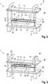
Ausgehend von dem ersten Zustand
In einem ersten Zustand
In dem ersten Zustand
Sollen die Teile
Die Aufnahme
Das Deckelelement
Die Teile
Ein zweiter Abschnitt
Mit einer zunehmenden Annährung der Teile
Das Deckelelement
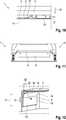
Die Kopplungsvorrichtung
Der zweite Anschluss
Der Druckstift
Die Segmente
Das Deckelelement
Ein zweiter Abschnitt
Mit einer zunehmenden Annährung der Teile
BezugszeichenlisteList of reference symbols
- 11
- KopplungsvorrichtungCoupling device
- 22
- erster Anschlussfirst connection
- 33
- zweiter Anschlusssecond connection
- 44th
- erstes Teilfirst part
- 55
- DruckstiftPush pin
- 66th
- zweites Teilsecond part
- 77th
- Aufnahmeadmission
- 88th
- erster Zustandfirst state
- 99
- DeckelelementCover element
- 1010
- UmgebungSurroundings
- 1111th
- zweiter Zustandsecond state
- 1212th
- erste Richtungfirst direction
- 1313th
- zweite Richtungsecond direction
- 1414th
- RückstellmechanismusReset mechanism
- 1515th
- AusgangsstellungStarting position
- 1616
- Segmentsegment
- 1717th
- AufnahmekanalRecording channel
- 1818th
- Führungguide
- 1919th
- Batteriebattery
- 2020th
- KraftfahrzeugMotor vehicle
- 2121
- erster Abschnittfirst section
- 2222nd
- zweiter Abschnittsecond part
- 2323
- erstes Endefirst end
- 2424
- zweites Endesecond end
ZITATE ENTHALTEN IN DER BESCHREIBUNGQUOTES INCLUDED IN THE DESCRIPTION
Diese Liste der vom Anmelder aufgeführten Dokumente wurde automatisiert erzeugt und ist ausschließlich zur besseren Information des Lesers aufgenommen. Die Liste ist nicht Bestandteil der deutschen Patent- bzw. Gebrauchsmusteranmeldung. Das DPMA übernimmt keinerlei Haftung für etwaige Fehler oder Auslassungen.This list of the documents listed by the applicant was generated automatically and is included solely for the better information of the reader. The list is not part of the German patent or utility model application. The DPMA assumes no liability for any errors or omissions.
Zitierte PatentliteraturPatent literature cited
- DE 102012205414 B3 [0010]DE 102012205414 B3 [0010]
- DE 102009019185 A1 [0011]DE 102009019185 A1 [0011]
Claims (10)
Translated fromGermanPriority Applications (1)
| Application Number | Priority Date | Filing Date | Title |
|---|---|---|---|
| DE102020115415.1ADE102020115415A1 (en) | 2020-06-10 | 2020-06-10 | Coupling device for connecting high-voltage connections |
Applications Claiming Priority (1)
| Application Number | Priority Date | Filing Date | Title |
|---|---|---|---|
| DE102020115415.1ADE102020115415A1 (en) | 2020-06-10 | 2020-06-10 | Coupling device for connecting high-voltage connections |
Publications (1)
| Publication Number | Publication Date |
|---|---|
| DE102020115415A1true DE102020115415A1 (en) | 2021-12-16 |
Family
ID=78718730
Family Applications (1)
| Application Number | Title | Priority Date | Filing Date |
|---|---|---|---|
| DE102020115415.1APendingDE102020115415A1 (en) | 2020-06-10 | 2020-06-10 | Coupling device for connecting high-voltage connections |
Country Status (1)
| Country | Link |
|---|---|
| DE (1) | DE102020115415A1 (en) |
Citations (11)
| Publication number | Priority date | Publication date | Assignee | Title |
|---|---|---|---|---|
| DE7110140U (en) | 1971-03-17 | 1971-07-08 | Nonkovik Dusan | SOCKET LID WITH FUSE BOARD PLUG WITH SLOTTED LEVER |
| US4176897A (en) | 1976-11-19 | 1979-12-04 | Bunker Ramo Corporation | EMI protected connector assembly |
| US4493517A (en) | 1980-12-03 | 1985-01-15 | Wkr Limited | Electrical socket connector |
| DE3604764A1 (en) | 1986-02-14 | 1987-08-20 | Dynamit Nobel Ag | ELECTRICAL CONNECTOR |
| EP0874378A2 (en) | 1997-04-25 | 1998-10-28 | SUMITOMO WIRING SYSTEMS, Ltd. | Charging connector for electric vehicle |
| DE102009019185A1 (en) | 2009-04-22 | 2010-10-28 | Dieter Kitto Werkzeug- Und Maschinenbau Gmbh | Changing device for rechargeable batteries in battery exchange station for electrically powered vehicles, has handling device for removing rechargeable battery from motor vehicle |
| US20130017696A1 (en) | 2011-07-11 | 2013-01-17 | Apple Inc. | Magnetically activated connector port cover |
| DE102012205414B3 (en) | 2012-04-03 | 2013-09-05 | Schaeffler Technologies AG & Co. KG | Electrically powered vehicle has removable traction battery that is arranged in underbody-sided constructed space, where transmission unit is provided for fixed interlocking of traction battery in underbody-sided constructed space |
| US20180186243A1 (en) | 2017-01-04 | 2018-07-05 | Nio Co., Ltd. | Fully-automatic dust proof system for quick change connector of electric vehicle |
| US20180248295A1 (en) | 2015-11-17 | 2018-08-30 | Hewlett-Packard Development Company, L.P. | Device connectors |
| DE102018203162A1 (en) | 2018-03-02 | 2019-09-05 | Bayerische Motoren Werke Aktiengesellschaft | Plug-in system for charging an electrical energy store |
- 2020
- 2020-06-10DEDE102020115415.1Apatent/DE102020115415A1/enactivePending
Patent Citations (11)
| Publication number | Priority date | Publication date | Assignee | Title |
|---|---|---|---|---|
| DE7110140U (en) | 1971-03-17 | 1971-07-08 | Nonkovik Dusan | SOCKET LID WITH FUSE BOARD PLUG WITH SLOTTED LEVER |
| US4176897A (en) | 1976-11-19 | 1979-12-04 | Bunker Ramo Corporation | EMI protected connector assembly |
| US4493517A (en) | 1980-12-03 | 1985-01-15 | Wkr Limited | Electrical socket connector |
| DE3604764A1 (en) | 1986-02-14 | 1987-08-20 | Dynamit Nobel Ag | ELECTRICAL CONNECTOR |
| EP0874378A2 (en) | 1997-04-25 | 1998-10-28 | SUMITOMO WIRING SYSTEMS, Ltd. | Charging connector for electric vehicle |
| DE102009019185A1 (en) | 2009-04-22 | 2010-10-28 | Dieter Kitto Werkzeug- Und Maschinenbau Gmbh | Changing device for rechargeable batteries in battery exchange station for electrically powered vehicles, has handling device for removing rechargeable battery from motor vehicle |
| US20130017696A1 (en) | 2011-07-11 | 2013-01-17 | Apple Inc. | Magnetically activated connector port cover |
| DE102012205414B3 (en) | 2012-04-03 | 2013-09-05 | Schaeffler Technologies AG & Co. KG | Electrically powered vehicle has removable traction battery that is arranged in underbody-sided constructed space, where transmission unit is provided for fixed interlocking of traction battery in underbody-sided constructed space |
| US20180248295A1 (en) | 2015-11-17 | 2018-08-30 | Hewlett-Packard Development Company, L.P. | Device connectors |
| US20180186243A1 (en) | 2017-01-04 | 2018-07-05 | Nio Co., Ltd. | Fully-automatic dust proof system for quick change connector of electric vehicle |
| DE102018203162A1 (en) | 2018-03-02 | 2019-09-05 | Bayerische Motoren Werke Aktiengesellschaft | Plug-in system for charging an electrical energy store |
Similar Documents
| Publication | Publication Date | Title |
|---|---|---|
| DE102019203193A1 (en) | Connector assembly for connecting and disconnecting electrical lines | |
| WO2015062582A1 (en) | Electric plug-in connection, in particular for electric vehicles | |
| EP2547541B1 (en) | Coupling between a replaceable battery and a vehicle | |
| DE102013202591A1 (en) | Charging device for an electric vehicle | |
| DE102012101803A1 (en) | Stromquellenschaltkreisabschaltvorrichtung | |
| DE102010041323A1 (en) | Charging device for charging battery of electric car in charging station, has drive unit for moving electrical contacts from initial position into end position for connecting to electrical contacts of another charging device | |
| DE102010042306A1 (en) | High voltage safety device for a high voltage battery | |
| DE102012215205A1 (en) | Cell connector for use in battery cell module of battery in e.g. electromotive drivable motor car, has access devices connecting connector with terminals of cells, where covering device with which one of access devices is partly covered | |
| DE102010010815A1 (en) | Busbar panel with spring-mounted busbars | |
| DE102016015316A1 (en) | On-board DC charging device for a vehicle | |
| EP3969347A1 (en) | Electric train coupling plug contact, electric train coupling half with an electric train coupling plug contact, electric train coupling and train coupling half and train coupling | |
| DE102020111610A1 (en) | Locking mechanism for a high-current connector | |
| DE102021110895A1 (en) | Battery module for a motor vehicle and method for its manufacture | |
| DE102012012154A1 (en) | Housing for receiving at least one battery cell, contacting device, battery system and vehicle | |
| DE102020115415A1 (en) | Coupling device for connecting high-voltage connections | |
| DE102019121975A1 (en) | Electric pull coupling and pull coupling with such an electric pull coupling | |
| DE102019128509A1 (en) | Locking system for a high-voltage connection | |
| DE102018010105A1 (en) | vehicle battery | |
| WO2015062581A1 (en) | Electric plug-in connection comprising an actuator and bowden cable, in particular for electric vehicles | |
| DE102021202381A1 (en) | Apparatus, method and system for securing a rechargeable electrical energy storage module | |
| DE102014017869A1 (en) | Plug device for electrically connecting two battery units of a motor vehicle | |
| DE102019119465A1 (en) | Electrical connection device | |
| DE102014000966A1 (en) | Cable management arrangement and method for their electrical connection | |
| WO2014053303A1 (en) | Storage cell and storage module | |
| DE102012214118A1 (en) | Safety plug for securing battery e.g. lithium-ion-battery, of motor vehicle, has operating element arranged at base, and sealing membrane made from plastic or metal and arranged above opened area of plug in position of operating element |
Legal Events
| Date | Code | Title | Description |
|---|---|---|---|
| R163 | Identified publications notified |