DE102020114552A1 - Odor trap device for urinals - Google Patents
Odor trap device for urinalsDownload PDFInfo
- Publication number
- DE102020114552A1 DE102020114552A1DE102020114552.7ADE102020114552ADE102020114552A1DE 102020114552 A1DE102020114552 A1DE 102020114552A1DE 102020114552 ADE102020114552 ADE 102020114552ADE 102020114552 A1DE102020114552 A1DE 102020114552A1
- Authority
- DE
- Germany
- Prior art keywords
- sealing
- odor trap
- trap device
- sealing membrane
- pipe section
- Prior art date
- Legal status (The legal status is an assumption and is not a legal conclusion. Google has not performed a legal analysis and makes no representation as to the accuracy of the status listed.)
- Pending
Links
Images


Classifications
- E—FIXED CONSTRUCTIONS
- E03—WATER SUPPLY; SEWERAGE
- E03D—WATER-CLOSETS OR URINALS WITH FLUSHING DEVICES; FLUSHING VALVES THEREFOR
- E03D13/00—Urinals ; Means for connecting the urinal to the flushing pipe and the wastepipe; Splashing shields for urinals
- E03D13/007—Waterless or low-flush urinals; Accessories therefor
- E—FIXED CONSTRUCTIONS
- E03—WATER SUPPLY; SEWERAGE
- E03C—DOMESTIC PLUMBING INSTALLATIONS FOR FRESH WATER OR WASTE WATER; SINKS
- E03C1/00—Domestic plumbing installations for fresh water or waste water; Sinks
- E03C1/12—Plumbing installations for waste water; Basins or fountains connected thereto; Sinks
- E03C1/28—Odour seals
- E03C1/298—Odour seals consisting only of non-return valve
Landscapes
- Engineering & Computer Science (AREA)
- Health & Medical Sciences (AREA)
- Life Sciences & Earth Sciences (AREA)
- Hydrology & Water Resources (AREA)
- Public Health (AREA)
- Water Supply & Treatment (AREA)
- Environmental & Geological Engineering (AREA)
- Sink And Installation For Waste Water (AREA)
- Bidet-Like Cleaning Device And Other Flush Toilet Accessories (AREA)
- Separation Using Semi-Permeable Membranes (AREA)
- Sanitary Device For Flush Toilet (AREA)
Abstract
Translated fromGermanDescription
Translated fromGermanDie Erfindung betrifft eine Geruchsverschlusseinrichtung für Urinale, einen Duftspender für eine Geruchsverschlusseinrichtung, einen Urinaleinsatz mit einer Geruchsverschlusseinrichtung und einem daran gekoppelten Duftspender und ein Set mit einer Geruchsverschlusseinrichtung und einem daran ankoppelbaren Duftspender.The invention relates to an odor trap device for urinals, a fragrance dispenser for an odor trap device, a urinal insert with an odor trap device and a fragrance dispenser coupled to it, and a set with an odor trap device and a fragrance dispenser that can be coupled to it.
Im Bereich von Sanitäranlagen gibt es seit geraumer Zeit Bestrebungen, einen möglichst ressourcenschonenden und damit nachhaltigen Betrieb solcher Anlagen zu erreichen. Aus diesem Grund sind beispielsweise bereits seit vielen Jahrzehnten sogenannte „Trockenurinale“ bekannt, die größtenteils oder sogar vollständig ohne Wasser bzw. Spülvorrichtung auskommen. Diese Trockenurinale, die auch als spülwasserlose Urinale bezeichnet werden, haben zwar den Vorteil, dass sie durch den Verzicht auf Spülwasser besonders ressourcenschonend arbeiten. Allerdings muss auch ohne Spülwasser sichergestellt sein, dass sich im Betrieb keine unangenehmen Gerüche im Trockenurinal bilden.In the area of sanitary facilities, efforts have been made for some time to achieve the most resource-saving and thus sustainable operation of such facilities. For this reason, so-called “dry urinals”, for example, have been known for many decades, which for the most part or even completely manage without water or flushing devices. These dry urinals, which are also known as urinals without flushing water, have the advantage that they work in a particularly resource-saving manner because they do not use flushing water. However, even without flushing water, it must be ensured that no unpleasant odors form in the dry urinal during operation.
Daher ist eine wirksame Geruchsunterbindung bzw. Geruchsunterdrückung bei der Verwendung eines Trockenurinals ein wichtiger Aspekt. Zur Vermeidung von unerwünschten Gerüchen umfasst ein Trockenurinal üblicherweise eine sogenannte „Geruchsverschlusseinrichtung“, beispielsweise einen mit einer Sperrflüssigkeit gefüllten Siphon, wobei die Sperrflüssigkeit vorzugsweise leichter als Urin und hydrophob ist, um so ein Entweichen von Gasen aus dem Trockenurinal zu unterbinden. Ein anderes bekanntes Funktionsprinzip einer Geruchsverschlusseinrichtung arbeitet mit einem Schwimmer in einem flüssigkeitsgefüllten Behälter, wobei der Schwimmer durch auftreffende Flüssigkeit niedergedrückt wird und anschließend wieder in eine Verschlussstellung zurückgedrückt wird.Effective odor suppression is therefore an important aspect when using a dry urinal. To avoid undesirable odors, a dry urinal usually includes a so-called “odor trap”, for example a siphon filled with a barrier liquid, the barrier liquid preferably being lighter than urine and hydrophobic in order to prevent gases from escaping from the dry urinal. Another known functional principle of an odor trap device works with a float in a liquid-filled container, the float being pressed down by incident liquid and then being pushed back into a closed position.
Ein drittes Funktionsprinzip von Geruchsverschlusseinrichtungen bedient sich einer Membran, die einen Abfluss eines Trockenurinals verschließt. Derartige Geruchsverschlusseinrichtungen werden üblicherweise in Form von wechselbaren Kartuschen bzw. Ventileinsätzen angeboten, die in einen Abfluss des Trockenurinals dichtend eingesetzt werden können, also in einen Bereich zwischen einem Becken des Urinals und einem Anschluss an die Kanalisation. Diese kartuschenartigen Geruchsverschlusseinrichtungen mit Dichtmembran können gegenüber den anderen Funktionsprinzipien den Vorteil haben, dass sie bei Bedarf relativ schnell und einfach ausgewechselt werden können, so dass Wartungsarbeiten am Trockenurinal auf ein Minimum reduziert werden können.A third functional principle of odor trap devices makes use of a membrane that closes an outflow of a dry urinal. Such odor trap devices are usually offered in the form of exchangeable cartridges or valve inserts, which can be inserted sealingly into a drain of the dry urinal, that is to say in an area between a basin of the urinal and a connection to the sewer system. These cartridge-like odor trap devices with sealing membrane can have the advantage over the other functional principles that they can be replaced relatively quickly and easily if necessary, so that maintenance work on the dry urinal can be reduced to a minimum.
Üblicherweise ist in einem Inneren einer solchen Kartusche eine Membran bzw. Dichtmembran angeordnet, die in einer Dichtstellung an einer innenliegenden Dichtwandung der Kartusche dichtend anliegt und so verhindert, dass unerwünschte Gerüche aus dem Urinal bzw. der Kanalisation durch die Kartusche ins Freie gelangen. Durch eine anstehende Flüssigkeit wie z.B. Urin kann die Dichtmembran von der Dichtwandung weggedrückt werden, wobei ein temporärer Spalt zwischen der Dichtmembran und der Dichtwandung zur Passage der Flüssigkeit entsteht, d.h. die Dichtmembran wird vorübergehend von der Dichtstellung in eine Öffnungsstellung bewegt und kehrt anschließend wieder von alleine in die Dichtstellung zurück.A membrane or sealing membrane is usually arranged in the interior of such a cartridge, which in a sealing position rests in a sealing position on an inner sealing wall of the cartridge and thus prevents undesirable odors from the urinal or the sewer system from escaping through the cartridge. A pending liquid such as urine can push the sealing membrane away from the sealing wall, creating a temporary gap between the sealing membrane and the sealing wall for the liquid to pass through, i.e. the sealing membrane is temporarily moved from the sealing position to an open position and then returns on its own back into the sealing position.
Ein Nachteil von bekannten Geruchsverschlusseinrichtungen mit Dichtmembran ist die vergleichsweise aufwendige konstruktive Ausgestaltung der Dichtmembran. So werden beispielweise u.a. kugelförmig, glockenförmig oder pilzförmig ausgebildete Dichtmembrane verwendet. Häufig benötigen derartige Dichtmembrane auch noch unterschiedliche funktionelle Bereiche bzw. Abschnitte, um eine zuverlässige Geruchsunterbindung zu erreichen. Beispielsweise ist es üblich, dass Dichtmembrane einen einlassseitigen Stauabschnitt zum Sammeln von Flüssigkeit oberhalb der Membran und einen sich in Abflussrichtung des Urins daran anschließenden Dichtabschnitt aufweisen, z.B. eine flächig an einer Dichtwandung anliegende Dichtfläche der Membran. Durch diese spezielle Konstruktion werden die Herstellungskosten von Dichtmembranen unnötigerweise erhöht.A disadvantage of known odor trap devices with a sealing membrane is the comparatively complex design of the sealing membrane. For example, spherical, bell-shaped or mushroom-shaped sealing membranes are used. Such sealing membranes often also require different functional areas or sections in order to achieve reliable odor suppression. For example, it is common for the sealing membrane to have an inlet-side damming section for collecting liquid above the membrane and a sealing section adjoining it in the outflow direction of the urine, e.g. a sealing surface of the membrane lying flat against a sealing wall. This special construction increases the manufacturing costs of sealing membranes unnecessarily.
Ein weiterer Nachteil von bekannten Dichtmembranen kann sich aus der Art und Weise der Halterung der Membran innerhalb der Geruchsverschlusseinrichtung ergeben. Insbesondere bei den zuvor genannten Membranen mit unterschiedlichen Funktionsabschnitten ist häufig auch eine relativ aufwendig konstruierte Haltevorrichtung nötig, um die Membran im Betrieb in einer bestimmungsgemäßen Position zu halten, insbesondere in Bezug auf eine Dichtwandung. Je nach Ausgestaltung der Membran kann auch noch eine zusätzliche Stützkonstruktion erforderlich sein, um die Membran selbst im Betrieb in einer gewünschten Form zu halten und so eine zuverlässige Geruchsunterbindung zu erreichen. Auch das kann zur Erhöhung der Herstellungskosten der Geruchsverschlusseinrichtung beitragen.Another disadvantage of known sealing membranes can result from the manner in which the membrane is held within the odor trap device. In particular in the case of the aforementioned membranes with different functional sections, a holding device of relatively complex design is often necessary in order to hold the membrane in an intended position during operation, in particular with respect to a sealing wall. Depending on the design of the membrane, an additional support structure may also be required in order to keep the membrane in a desired shape even during operation and thus to achieve reliable odor suppression. This can also contribute to increasing the manufacturing costs of the odor trap device.
Geruchsverschlusseinrichtungen der eingangs genannten Art mit einer Dichtmembran sind üblicherweise Einwegartikel und müssen daher regelmäßig ersetzt werden. Nicht zuletzt aus diesem Grund besteht ein großes Bedürfnis nach einer besonders kostengünstigen und zugleich wirksamen Geruchsverschlusseinrichtung mit Dichtmembran.Odor trap devices of the type mentioned at the beginning with a sealing membrane are usually disposable items and must therefore be replaced regularly. Not least for this reason, there is a great need for a particularly inexpensive and at the same time effective odor trap device with a sealing membrane.
Es ist daher eine Aufgabe der vorliegenden Erfindung, eine Geruchsverschlusseinrichtung für Urinale, einen Duftspender für eine Geruchsverschlusseinrichtung, einen Urinaleinsatz mit einer Geruchsverschlusseinrichtung und einem daran gekoppelten Duftspender und ein Set mit einer Geruchsverschlusseinrichtung und einem daran ankoppelbaren Duftspender bereit zu stellen, mit dem die zuvor erläuterten Nachteile vermieden werden können.It is therefore an object of the present invention to provide an odor trap device for urinals, a fragrance dispenser for an odor trap device, a urinal insert with an odor trap device and a fragrance dispenser coupled to it and a set with an odor trap device and a fragrance dispenser that can be coupled to it, with which the previously explained Disadvantages can be avoided.
Diese Aufgabe wird durch eine Geruchsverschlusseinrichtung für Urinale gemäß Patentanspruch 1, einen Duftspender nach Patentanspruch 13 sowie durch einen Urinaleinsatz nach Patentanspruch 14 und ein Set nach Patentanspruch 15 gelöst.This object is achieved by an odor trap device for urinals according to
Eine erfindungsgemäße Geruchsverschlusseinrichtung für Urinale, insbesondere für Trockenurinale, umfasst ein Einlasselement für eine Flüssigkeit, insbesondere für Urin, und ein damit gekoppeltes Auslasselement für die Flüssigkeit, wobei das Auslasselement ein Rohrstück aufweist. Die Geruchsverschlusseinrichtung ist bevorzugt in Form einer eingangs genannten Kartusche ausgebildet und ist insbesondere dazu bestimmt, in einen Abfluss eines Trockenurinals wechselbar eingesetzt zu werden. Diesbezüglich wird auf die einleitenden Ausführungen Bezug genommen. Eine bestimmungsgemäße Verwendung der Geruchsverschlusseinrichtung in einem Urinal vorausgesetzt, wird unter dem Einlasselement ein Teil der Geruchsverschlusseinrichtung verstanden, der einem (Sammel-)Becken des Urinals zugewandt ist. Entsprechend bezeichnet das Auslasselement einen der Kanalisation zugewandten Teil der Geruchsverschlusseinrichtung.An odor trap device according to the invention for urinals, in particular for dry urinals, comprises an inlet element for a liquid, in particular for urine, and an outlet element for the liquid coupled therewith, the outlet element having a piece of pipe. The odor trap device is preferably designed in the form of a cartridge mentioned at the beginning and is in particular intended to be inserted exchangeably in a drain of a dry urinal. In this regard, reference is made to the introductory remarks. Provided that the odor trap device is used as intended in a urinal, the inlet element is understood to mean a part of the odor trap device that faces a (collecting) basin of the urinal. Correspondingly, the outlet element designates a part of the odor trap device facing the sewer system.
Die Geruchsverschlusseinrichtung weist eine Dichtmembran und eine Halterung für die Dichtmembran auf. Die Dichtmembran wird nachfolgend synonym auch kurz als Membran bezeichnet. Erfindungsgemäß ist die Dichtmembran so in einem Inneren des Auslasselements, insbesondere im Rohrstück, angeordnet, dass die Dichtmembran in einer Dichtstellung der Dichtmembran mit einer Dichtwandung im Inneren des Rohrstücks dichtend zusammenwirkt. Dichtend Zusammenwirken heißt, dass bei bestimmungsgemäßer Verwendung der Geruchsverschlusseinrichtung im Wesentlichen keine Gerüche und/oder Gase aus der Kanalisation und/oder aus Bereichen des Urinals, die in Flussrichtung des Urins stromabwärts der Membran liegen, nach außerhalb bzw. nach oben über das Becken des Urinals austreten.The odor trap device has a sealing membrane and a holder for the sealing membrane. The sealing membrane is hereinafter also referred to synonymously as the membrane for short. According to the invention, the sealing membrane is arranged in an interior of the outlet element, in particular in the pipe section, that the sealing membrane interacts in a sealing position of the sealing membrane with a sealing wall in the interior of the pipe section. Sealing interaction means that when the odor trap device is used as intended, there are essentially no odors and / or gases from the sewer system and / or from areas of the urinal that are downstream of the membrane in the flow direction of the urine, to the outside or above the urinal basin step out.
Die Dichtmembran ist in einer „normally closed“ Position in der Geruchsverschlusseinrichtung angeordnet. Mit anderen Worten ist die Dichtmembran so im Rohrstück angeordnet, dass die Dichtmembran in einer Ruhestellung bzw. Normalstellung der Membran, also insbesondere wenn gerade keine Flüssigkeit durch das Urinal fließt, in der Dichtstellung angeordnet ist.The sealing membrane is arranged in a “normally closed” position in the odor trap device. In other words, the sealing membrane is arranged in the pipe section in such a way that the sealing membrane is arranged in the sealing position in a rest position or normal position of the membrane, that is to say in particular when no liquid is currently flowing through the urinal.
Die Dichtmembran ist so gelagert, dass sie durch eine vom Einlasselement her an der Membran anstehende Flüssigkeit, z.B. Urin, von der Dichtstellung in eine Öffnungsstellung der Dichtmembran bewegt wird. Das zeitweise und reversible Öffnen der Dichtmembran zur Passage der Flüssigkeit erfolgt also durch Schwerkraft.The sealing membrane is mounted in such a way that it is moved from the sealing position to an open position of the sealing membrane by a liquid, e.g. urine, which is present on the membrane from the inlet element. The temporary and reversible opening of the sealing membrane for the passage of the liquid is therefore carried out by gravity.
Erfindungsgemäß umfasst die Halterung für die Dichtmembran ein erstes Lagerelement, das im Einlasselement angeordnet ist. Bevorzugt ist das erste Lagerelement als Teil des Einlasselements ausgebildet. Dies wird später noch genauer beschrieben.According to the invention, the holder for the sealing membrane comprises a first bearing element which is arranged in the inlet element. The first bearing element is preferably designed as part of the inlet element. This will be described in more detail later.
Die Halterung umfasst ein zweites Lagerelement, das separat gegenüber dem ersten Lagerelement ausgebildet ist. Erfindungsgemäß ist das zweite Lagerelement im Auslasselement angeordnet, d.h. das zweite Lagerelement ist räumlich getrennt vom ersten Lagerelement angeordnet. Das erste Lagerelement und das zweite Lagerelement sind so ausgebildet und so zueinander angeordnet, dass sie zur bestimmungsgemäßen Halterung bzw. Lagerung der Dichtmembran relativ zur Dichtwandung funktional zusammenwirken.The holder comprises a second bearing element which is formed separately from the first bearing element. According to the invention, the second bearing element is arranged in the outlet element, i.e. the second bearing element is arranged spatially separated from the first bearing element. The first bearing element and the second bearing element are designed and arranged with respect to one another in such a way that they functionally cooperate for the intended holding or mounting of the sealing membrane relative to the sealing wall.
Das erste Lagerelement und das zweite Lagerelement sind als separate Bauteile ausgebildet. Das bedeutet, die beiden Lagerelemente sind so angeordnet, dass sie zur Halterung der Dichtmembran vorzugsweise keinen direkten, unmittelbaren Kontakt zueinander haben. Mit anderen Worten berühren das erste Lagerelement und das zweite Lagerelement einander zur Halterung der Dichtmembran nicht unmittelbar.The first bearing element and the second bearing element are designed as separate components. This means that the two bearing elements are arranged in such a way that they preferably have no direct, immediate contact with one another in order to hold the sealing membrane. In other words, the first bearing element and the second bearing element do not touch one another directly to hold the sealing membrane.
Erfindungsgemäß ist das erste Lagerelement auf einer ersten Seite bzw. Fläche der Dichtmembran angeordnet. Das zweite Lagerelement ist auf einer zweiten Seite bzw. Fläche der Dichtmembran angeordnet, wobei die zweite Seite der Dichtmembran der ersten Seite der Dichtmembran gegenüberliegt. Das bedeutet, das erste Lagerelement und das zweite Lagerelement sind auf zwei voneinander abgewandten Seiten bzw. Flächen der Dichtmembran angeordnet. Insbesondere sind das erste Lagerelement und das zweite Lagerelement so angeordnet, dass die Dichtmembran zwischen dem ersten Lagerelement und dem zweiten Lagerelement angeordnet ist und/oder gehalten wird, z.B. indem die Membran zwischen die beiden Lagerelemente geklemmt ist.According to the invention, the first bearing element is arranged on a first side or surface of the sealing membrane. The second bearing element is arranged on a second side or surface of the sealing membrane, the second side of the sealing membrane being opposite the first side of the sealing membrane. This means that the first bearing element and the second bearing element are arranged on two sides or surfaces of the sealing membrane facing away from one another. In particular, the first bearing element and the second bearing element are arranged such that the sealing membrane is arranged and / or held between the first bearing element and the second bearing element, e.g. by clamping the membrane between the two bearing elements.
Vorteilhafterweise kann durch die erfindungsgemäße Halterung für die Dichtmembran mit zwei separat ausgebildeten und funktional zusammenwirkenden Lagerelementen die Konstruktion der Haltevorrichtung gegenüber bekannten Geruchsverschlusseinrichtungen vereinfacht werden, wobei dennoch eine gewünschte Anordnung der Dichtmembran im Auslasselement und damit eine zuverlässige Geruchsunterbindung im Betrieb gewährleistet ist. Insbesondere im Vergleich zu bekannten Geruchsverschlusseinrichtungen mit nur einer einzigen und damit häufig sehr aufwendig konstruierten Halterung für die Membran, können bei der erfindungsgemäßen Geruchsverschlusseinrichtung zwei vergleichsweise einfach zu konstruierenden Lagerelemente verwendet werden, da sich die Haltefunktion hier erst aus einem Synergismus der zwei separaten aber zusammenwirkenden Lagerelemente ergibt. Vorteilhafterweise sind daher die konstruktiven Anforderungen an die beiden Lagerelemente vergleichsweise gering, so dass die Herstellungskosten der Halterung und damit der Geruchsverschlusseinrichtung insgesamt reduziert werden können.Advantageously, by means of the holder according to the invention for the sealing membrane with two separately designed and functionally interacting bearing elements, the construction of the Holding device can be simplified compared to known odor trap devices, with a desired arrangement of the sealing membrane in the outlet element and thus a reliable odor suppression during operation being guaranteed. In particular in comparison to known odor trap devices with only a single and therefore often very complexly constructed holder for the membrane, two bearing elements that are comparatively easy to construct can be used in the case of the odor trap device according to the invention, since the holding function here results from a synergism of the two separate but interacting bearing elements results. The structural requirements for the two bearing elements are therefore advantageously comparatively low, so that the production costs of the holder and thus of the odor trap device can be reduced overall.
Weiterhin vorteilhaft ermöglicht die erfindungsgemäße Halterung gerade wegen der funktionellen Interaktion von zwei Lagerelementen, die auf einander gegenüberliegenden Seiten einer Dichtmembran angeordnet sind, die Verwendung von geometrisch relativ einfach ausgestalteten Dichtmembranen, die im Vergleich zu den bekannten o.g. komplexeren Dichtmembranen vergleichsweise günstig herzustellen sind. Auch aus diesem Grund können die Herstellungskosten der Geruchsverschlusseinrichtung insgesamt reduziert werden. Dies wird später noch genauer beschrieben.Furthermore, because of the functional interaction of two bearing elements that are arranged on opposite sides of a sealing membrane, the holder according to the invention advantageously enables the use of geometrically relatively simple sealing membranes, which are comparatively inexpensive to manufacture compared to the known, more complex sealing membranes. For this reason, too, the production costs of the odor trap device can be reduced overall. This will be described in more detail later.
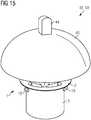
Die Erfindung betrifft weiterhin einen Duftspender für eine Geruchsverschlusseinrichtung, insbesondere einen Duftspender für eine zuvor beschriebene erfindungsgemäße Geruchsverschlusseinrichtung. Erfindungsgemäß weist der Duftspender ein Kopplungselement zur Kopplung an eine Geruchsverschlusseinrichtung auf, vorzugsweise ein Kopplungselement zur Kopplung an eine erfindungsgemäße Geruchsverschlusseinrichtung. Ein erfindungsgemäßer Duftspender ist dazu ausgebildet, im Betrieb eines Urinals, insbesondere bei Kontakt mit einer Flüssigkeit, einen angenehmen Duft in eine ihn umgebende Atmosphäre abzugeben und/oder eine äußere Optik einer Geruchsverschlusseinrichtung aufzuwerten, sofern der Duftspender bestimmungsgemäß an die Geruchsverschlusseinrichtung gekoppelt ist. Details zum Duftspender und zum Kopplungsmechanismus werden später gegeben.The invention further relates to a fragrance dispenser for an odor trap device, in particular a fragrance dispenser for a previously described odor trap device according to the invention. According to the invention, the fragrance dispenser has a coupling element for coupling to an odor trap device, preferably a coupling element for coupling to an odor trap device according to the invention. A fragrance dispenser according to the invention is designed to emit a pleasant fragrance into a surrounding atmosphere when a urinal is in operation, especially when it comes into contact with a liquid, and / or to enhance the external appearance of an odor trap, provided that the fragrance dispenser is properly coupled to the odor trap. Details about the fragrance dispenser and the coupling mechanism will be given later.
Die Erfindung betrifft weiterhin einen Urinaleinsatz mit einer Geruchsverschlusseinrichtung, insbesondere einen Urinaleinsatz mit einer zuvor beschriebenen erfindungsgemäßen Geruchsverschlusseinrichtung. Erfindungsgemäß weist der Urinaleinsatz ein an die Geruchsverschlusseinrichtung gekoppelten Duftspender auf, insbesondere einen zuvor beschriebenen erfindungsgemäßen Duftspender.The invention further relates to a urinal insert with an odor trap device, in particular a urinal insert with a previously described odor trap device according to the invention. According to the invention, the urinal insert has a fragrance dispenser coupled to the odor trap device, in particular a fragrance dispenser according to the invention described above.
Die Erfindung betrifft weiterhin ein Set mit einer Geruchsverschlusseinrichtung, insbesondere mit einer zuvor beschriebenen erfindungsgemäßen Geruchsverschlusseinrichtung und einem an die Geruchsverschlusseinrichtung ankoppelbaren Duftspender. Insbesondere umfasst das Set einen zuvor beschriebenen erfindungsgemäßen Duftspender.The invention further relates to a set with an odor trap device, in particular with a previously described odor trap device according to the invention and a fragrance dispenser that can be coupled to the odor trap device. In particular, the set comprises a previously described fragrance dispenser according to the invention.
Vorteilhafterweise kann durch den erfindungsgemäßen Duftspender, insbesondere in Kombination mit einer erfindungsgemäßen Geruchsverschlusseinrichtung, z.B. in Form eines zuvor beschriebenen Urinaleinsatzes oder eines Sets, die Benutzung eines Urinals für einen Nutzer angenehmer gestaltet werden. Einerseits sorgt der erfindungsgemäße Duftspender dafür, dass ggf. vorhandene unangenehme Gerüche im Bereich eines Urinals, z.B. ausgehend vom Sammelbecken, zuverlässig überdeckt werden und für den Nutzer ein positives Geruchserlebnis entsteht. Andererseits kann der Duftspender auch dazu beitragen, die Optik einer Geruchsverschlusseinrichtung und damit das Erscheinungsbild eines Urinals, insbesondere eines Trockenurinals, insgesamt aufzuwerten. Besonders vorteilhaft ist, dass der Duftspender im (Trocken-)Urinal in Kombination mit einer erfindungsgemäßen Geruchsverschlusseinrichtung eingesetzt werden kann, sodass sich die genannten Vorteile der erfindungsgemäßen Geruchsverschlusseinrichtung und des erfindungsgemäßen Duftspenders ergänzen.The fragrance dispenser according to the invention, in particular in combination with an odor trap device according to the invention, e.g. in the form of a urinal insert or a set described above, can advantageously make the use of a urinal more pleasant for a user. On the one hand, the fragrance dispenser according to the invention ensures that any unpleasant smells that may be present in the area of a urinal, e.g. originating from the collecting basin, are reliably covered and that a positive odor experience is created for the user. On the other hand, the fragrance dispenser can also contribute to upgrading the appearance of an odor trap device and thus the appearance of a urinal, in particular a dry urinal, as a whole. It is particularly advantageous that the fragrance dispenser can be used in the (dry) urinal in combination with an odor trap device according to the invention, so that the stated advantages of the odor trap device according to the invention and the fragrance dispenser according to the invention complement each other.
Weitere, besonders vorteilhafte Ausgestaltungen und Weiterbildungen der Erfindung ergeben sich aus den abhängigen Ansprüchen sowie der nachfolgenden Beschreibung, wobei die unabhängigen Ansprüche einer Anspruchskategorie auch analog zu den abhängigen Ansprüchen und Ausführungsbeispielen einer anderen Anspruchskategorie weitergebildet sein können und insbesondere auch einzelne Merkmale verschiedener Ausführungsbeispiele bzw. Varianten zu neuen Ausführungsbeispielen bzw. Varianten kombiniert werden können.Further, particularly advantageous configurations and developments of the invention emerge from the dependent claims and the following description, whereby the independent claims of one claim category can also be developed analogously to the dependent claims and exemplary embodiments of another claim category and in particular also individual features of various exemplary embodiments or variants can be combined to new embodiments or variants.
Das Einlasselement der Geruchsverschlusseinrichtung umfasst zumindest eine Einlauföffnung bzw. Eintrittsöffnung für eine Flüssigkeit, z.B. Urin, über welche die Flüssigkeit in ein Inneres der Geruchsverschlusseinrichtung eintreten kann. Nachfolgend wird der besseren Verständlichkeit wegen davon ausgegangen, dass es sich bei der Flüssigkeit um Urin handelt, da dies dem bevorzugten Verwendungszweck der Geruchsverschlusseinrichtung entspricht. Das schließt allerdings nicht aus, dass auch andere Flüssigkeiten durch die Geruchsverschlusseinrichtung strömen können, z.B. Gemische von Urin und Spülwasser, flüssige und/oder partikuläre Duftstoffe, Reinigungsmittel, ggf. Fremdkörper etc.The inlet element of the odor trap device comprises at least one inlet opening or inlet opening for a liquid, for example urine, via which the liquid can enter an interior of the odor trap device. In the following, for the sake of better understanding, it is assumed that the liquid is urine, since this corresponds to the preferred purpose of the odor trap device. However, this does not rule out that other liquids can also flow through the odor trap device, e.g. mixtures of urine and rinse water, liquid and / or particulate fragrances, cleaning agents, possibly foreign bodies, etc.
Bevorzugt bildet eine bei bestimmungsgemäßer Verwendung der Geruchsverschlusseinrichtung nach „oben“, d.h. in Richtung eines Sammelbeckens eines Urinals weisende Seite bzw. Oberfläche des Einlasselements eine „Eintrittsseite“ des Einlasselements aus. Das bedeutet, die Eintrittsseite umfasst zumindest eine Einlauföffnung und bildet bei bestimmungsgemäßer Verwendung der Geruchsverschlusseinrichtung in einem Urinal den für einen Nutzer sichtbaren Teil der Geruchsverschlusseinrichtung. Im Rahmen der Anmeldung ist unter dem Begriff „Urinal“ insbesondere auch ein Trockenurinal zu verstehen, da die vorteilhaften Effekte besonders bei spülwasserlosen Trockenurinalen zur Geltung kommen. Allerdings kann die Geruchsverschlusseinrichtung grundsätzlich auch bei herkömmlichen Urinalen mit einer Wasserspülung verwendet werden, so dass keine Beschränkung auf ein Trockenurinal erfolgen soll.When the odor trap device is used as intended, a side or surface of the inlet element pointing upwards, ie in the direction of a collecting basin of a urinal, preferably forms an “entry side” of the inlet element. This means that the entry side comprises at least one inlet opening and, when the odor trap device is used as intended in a urinal, forms the part of the odor trap device that is visible to a user. In the context of the application, the term “urinal” is also to be understood in particular as a dry urinal, since the advantageous effects are particularly effective in the case of dry urinals without flushing water. However, the odor trap device can in principle also be used in conventional urinals with a water flush, so that there should not be any restriction to a dry urinal.
Das Einlasselement kann Komponenten zur Befestigung der Geruchsverschlusseinrichtung im Abfluss eines Urinals aufweisen. Vorzugsweise kann ein Bereich des Einlasselements als Flansch ausgebildet sein. Weiterhin kann das Einlasselement Dichtelemente umfassen, um das Einlasselement dichtend in einen Abfluss eines (Sammel-)Beckens eines Urinals einzulassen. Dies wird später noch beschrieben.The inlet element can have components for fastening the odor trap device in the drain of a urinal. A region of the inlet element can preferably be designed as a flange. Furthermore, the inlet element can comprise sealing elements in order to admit the inlet element in a sealing manner into a drain of a (collecting) basin of a urinal. This will be described later.
Auf einer von der Eintrittsseite abgewandten Seite des Einlasselements hat das Einlasselement Kontakt mit dem Auslasselement. Vorzugsweise sind das Einlasselement und das Auslasselement durch Stoffschluss miteinander verbunden. Bevorzugt können die beiden Elemente mittels eines Spritzgussverfahrens gemeinsam als ein Teil hergestellt werden.On a side of the inlet element facing away from the inlet side, the inlet element is in contact with the outlet element. The inlet element and the outlet element are preferably connected to one another by a material bond. The two elements can preferably be produced together as one part by means of an injection molding process.
Das Auslasselement ist besonders bevorzugt mittels eines Rohrstücks ausgebildet. Deshalb wird das Auslasselement nachfolgend synonym auch als Rohrstück bezeichnet. Vorzugsweise hat das Rohrstück einen im Wesentlichen kreisrunden Querschnitt. Das Rohrstück kann an einer Außenseite des Rohrstücks Komponenten zur Befestigung der Geruchsverschlusseinrichtung im Abfluss eines Urinals aufweisen. Vorzugsweise kann das Rohrstück eine Anzahl von Hinterschneidungen haben, welche nach der Art eines Bajonettverschlusses mit einem Abflussrohr oder ggf. mit einem Adapter verrastet werden können. Alternativ kann eine Außenseite des Rohrstücks zumindest bereichsweise ein (Außen-)Gewinde umfassen, wobei die Geruchsverschlusseinrichtung dann im Abflussrohr oder ggf. mit einem Adapter verschraubt werden kann.The outlet element is particularly preferably designed by means of a pipe section. The outlet element is therefore also referred to synonymously below as a pipe section. The pipe section preferably has an essentially circular cross section. The pipe section can have components on an outside of the pipe section for fastening the odor trap device in the drain of a urinal. The pipe section can preferably have a number of undercuts which can be latched in the manner of a bayonet lock with a drain pipe or, if necessary, with an adapter. Alternatively, an outer side of the pipe section can comprise an (outer) thread, at least in some areas, in which case the odor trap device can then be screwed into the drainage pipe or, if necessary, with an adapter.
Das Rohrstück ist einerseits dazu ausgebildet, um über seine innenliegende Dichtwandung einen weitestgehend gasdichten Kontakt zur Dichtmembran herzustellen (sofern die Dichtmembran in der Dichtstellung ist). Dazu ist zumindest ein Teilbereich einer Innenwandung des Rohrstücks als Dichtwandung ausgebildet.The pipe section is designed on the one hand to produce a largely gas-tight contact with the sealing membrane via its inner sealing wall (provided the sealing membrane is in the sealing position). For this purpose, at least a partial area of an inner wall of the pipe section is designed as a sealing wall.
Andererseits ist das Rohrstück auch dazu ausgebildet, um mit einem Endbereich eine Verbindung zu Bereichen des Urinals herzustellen, die entsprechend einer Strömungsrichtung (bzw. Abflussrichtung) des Urins stromabwärts der Dichtmembran liegen, und/oder zur Kanalisation herzustellen. Bei einer bestimmungsgemäßen Verwendung der Geruchsverschlusseinrichtung im Urinal tritt das Urin also in eine Eintrittsöffnung des Einlasselements ein, strömt von dort in das Rohrstück ein, wobei es die Dichtmembran passiert und tritt dann über einen stromabwärts (in Flussrichtung des Urins) gelegenen Endbereich des Rohrstücks bzw. über ein Auslassende des Auslasselements wieder aus der Geruchsverschlusseinrichtung aus. Der zuvor beschriebene Weg von Urin durch die Geruchsverschlusseinrichtung entspricht einer Strömungsrichtung des Urins.On the other hand, the pipe section is also designed to establish a connection with one end area to areas of the urinal that are downstream of the sealing membrane in accordance with a flow direction (or outflow direction) of the urine, and / or to the sewer system. When the odor trap device is used as intended in the urinal, the urine enters an inlet opening of the inlet element, flows from there into the pipe section, where it passes the sealing membrane and then passes through an end region of the pipe section or pipe section located downstream (in the flow direction of the urine). out of the odor trap device again via an outlet end of the outlet element. The path of urine through the odor trap device described above corresponds to a flow direction of the urine.
Zur Lagerung der Dichtmembran im Rohrstück macht sich die Erfindung, wie beschrieben, eine vergleichsweise einfach konstruierte aber dennoch zuverlässige Halterung zu Nutze. Bevorzugt kann die Halterung der Dichtmembran in einer Längsrichtung bzw. in einem Längsschnitt quasi „schichtweise“ aufgebaut sein. Unter einem Längsschnitt durch die Halterung und/oder durch die Geruchsverschlusseinrichtung wird ein Schnitt entlang einer Längserstreckung der Geruchsverschlusseinrichtung verstanden, d.h. eine entsprechende Schnittachse verläuft vom Einlasselement in Richtung des Auslasselements (entsprechend der Strömungsrichtung des Urins).For mounting the sealing membrane in the pipe section, the invention makes use, as described, of a comparatively simply constructed but nevertheless reliable holder. The mounting of the sealing membrane can preferably be built up “layer by layer” in a longitudinal direction or in a longitudinal section. A longitudinal section through the holder and / or through the odor trap device is understood to mean a section along a longitudinal extension of the odor trap device, i.e. a corresponding section axis runs from the inlet element in the direction of the outlet element (corresponding to the flow direction of the urine).
Die Halterung umfasst dann eine erste Schicht, die vorzugsweise durch das erste Lagerelement gebildet wird. Wie schon beschrieben, ist das erste Lagerelement als Bestandteil des Einlasselements ausgebildet. Insbesondere kann das erste Lagerelement durch Stoffschluss mit dem Einlasselement verbunden sein. Bevorzugt können das Einlasselement und das erste Lagerelement einstückig gefertigt sein, beispielsweise mittels eines Spritzgussverfahrens.The holder then comprises a first layer, which is preferably formed by the first bearing element. As already described, the first bearing element is designed as part of the inlet element. In particular, the first bearing element can be connected to the inlet element by a material bond. The inlet element and the first bearing element can preferably be manufactured in one piece, for example by means of an injection molding process.
Eine zweite Schicht, die stromabwärts (also in Richtung des Auslasselements weisend) an die erste Schicht angrenzt, kann vorzugsweise durch einen Bereich bzw. Abschnitt der Dichtmembran gebildet sein.A second layer, which adjoins the first layer downstream (ie pointing in the direction of the outlet element), can preferably be formed by a region or section of the sealing membrane.
An die Dichtmembran kann, wiederum stromabwärts, eine dritte Schicht angrenzen. Die dritte Schicht ist vorzugsweise durch das zweite Lagerelement gebildet. Das bedeutet, die Dichtmembran ist zur Halterung zwischen das erste Lagerelement und das zweite Lagerelement eingelegt bzw. eingeklemmt (in einem Längsschnitt durch die Halterung).A third layer can adjoin the sealing membrane, again downstream. The third layer is preferably formed by the second bearing element. This means that the sealing membrane is inserted or clamped between the first bearing element and the second bearing element for holding purposes (in a longitudinal section through the holding device).
Vorzugsweise hat die Dichtmembran also über eine erste Seite bzw. Oberfläche der Dichtmembran, nachfolgend Einlassseite genannt, (Wirk-)Kontakt zum ersten Lagerelement. Mit einer zweiten gegenüberliegenden Seite bzw. Oberfläche, nachfolgend Auslassseite genannt, hat die Dichtmembran dann (Wirk-)Kontakt zum zweiten Lagerelement.The sealing membrane preferably has (active) contact with the first bearing element via a first side or surface of the sealing membrane, hereinafter referred to as the inlet side. With a second opposite side or surface, hereinafter referred to as the outlet side, the sealing membrane then has (active) contact with the second bearing element.
Bevorzugt kann das erste Lagerelement in Richtung zum zweiten Lagerelement hin eine konkave Ausgestaltung haben. Insbesondere kann ein Kontaktbereich des ersten Lagerelements, über den das erste Lagerelement in Kontakt mit der Dichtmembran steht, eine konkave Ausgestaltung haben. Alternativ oder zusätzlich kann das zweite Lagerelement in Richtung zum ersten Lagerelement hin eine konvexe Ausgestaltung haben. Insbesondere kann ein Kontaktbereich des zweiten Lagerelements, über den das zweite Lagerelement in Kontakt mit der Dichtmembran steht, eine konvexe Ausgestaltung habenThe first bearing element can preferably have a concave configuration in the direction of the second bearing element. In particular, a contact area of the first bearing element, via which the first bearing element is in contact with the sealing membrane, can have a concave configuration. Alternatively or additionally, the second bearing element can have a convex configuration in the direction of the first bearing element. In particular, a contact area of the second bearing element, via which the second bearing element is in contact with the sealing membrane, can have a convex configuration
Vorteilhafterweise kann über die spezielle konkave und/oder konvexe Ausgestaltung der Lagerelemente noch besser erreicht werden, dass die Dichtmembran in einer gewünschten Dichtstellung im Rohrstück angeordnet ist. Vorteilhafterweise kann damit die Konstruktion der Dichtmembran weiter vereinfacht werden, so dass die Dichtmembran günstiger herzustellen ist. Die Dichtmembran wird durch die speziell ausgestalteten Lagerelemente quasi „automatisch“ in eine gewünschte Form gebogen und gehalten.Advantageously, the special concave and / or convex design of the bearing elements can achieve an even better result that the sealing membrane is arranged in a desired sealing position in the pipe section. Advantageously, the construction of the sealing membrane can thus be further simplified, so that the sealing membrane can be manufactured more cheaply. The sealing membrane is "automatically" bent into the desired shape and held by the specially designed bearing elements.
Vorzugsweise kann das erste Lagerelement so ausgebildet sein, dass es zur Halterung der Dichtmembran ein Widerlager gegenüber dem zweiten Lagerelement ausbildet. Um das erste Lagerelement und das zweite Lagerelement zur Halterung der Dichtmembran in Wirkkontakt miteinander zu bringen, kann das zweite Lagerelement vom Auslasselement her bis zum Erreichen einer Sollposition in das Rohrstück eingebracht werden. Vorzugsweise kann das zweite Lagerelement bis zum Erreichen einer Klemmstellung in das Rohrstück eingepresst werden. Das bedeutet, vorzugsweise „drückt“ das zweite Lagerelement die Dichtmembran vom Auslasselement her in Richtung des Einlasselements, wobei die Dichtmembran dem ersten Lagerelement als Gegenlager anliegt. Vorzugsweise kann die Dichtmembran so im Rohrstück angeordnet sein, insbesondere durch das Zusammenspiel von erstem und zweitem Lagerelement, dass die Dichtmembran unter einer Vorspannung gehalten wird, wobei die Dichtmembran auf Grund einer Rückstellkraft der Dichtmembran in der Dichtstellung angeordnet ist.The first bearing element can preferably be designed in such a way that it forms an abutment with respect to the second bearing element to hold the sealing membrane. In order to bring the first bearing element and the second bearing element for holding the sealing membrane into operative contact with one another, the second bearing element can be introduced into the pipe section from the outlet element until a target position is reached. The second bearing element can preferably be pressed into the pipe section until a clamping position is reached. This means that the second bearing element preferably “presses” the sealing membrane from the outlet element in the direction of the inlet element, the sealing membrane resting against the first bearing element as a counter-bearing. The sealing membrane can preferably be arranged in the pipe section, in particular through the interaction of the first and second bearing element, that the sealing membrane is held under a pretension, the sealing membrane being arranged in the sealing position due to a restoring force of the sealing membrane.
Vorteilhafterweise kann über das Zusammenspiel der beiden Lagerelemente eine zugleich robuste und vergleichsweise günstig herzustellende Halterung realisiert werden. Bei der Haltevorrichtung kann auf filigrane und aufwendig zu produzierende Stützelemente verzichtet werden, wie sie häufig bei anderen Geruchsverschlusseinrichtungen nötig sind. Sowohl die Herstellung des zweiten Lagerelements als auch die Montage der Membran im Rohrstück über das zweite Lagerelement, z.B. durch Eindrücken in das Rohrstück, sind relativ zeit- und kostensparend zu bewerkstelligen. Beispielsweise können das erste und das zweite Lagerelement auch getrennt voneinander produziert werden und erst bei Bedarf zur Halterung der Dichtmembran in Interaktion miteinander gebracht werden.Advantageously, through the interaction of the two bearing elements, a holder that is both robust and comparatively inexpensive can be realized. In the case of the holding device, filigree support elements, which are complex to produce, can be dispensed with, as are often necessary with other odor trap devices. Both the production of the second bearing element and the assembly of the membrane in the pipe section over the second bearing element, e.g. by pressing into the pipe section, can be accomplished in a relatively time-saving and cost-saving manner. For example, the first and the second bearing element can also be produced separately from one another and only brought into interaction with one another to hold the sealing membrane when required.
Vorzugsweise kann sich das zweite Lagerelement zur Lagerung der Dichtmembran an zwei diametral gegenüberliegenden Abstützbereichen im Rohrstück abstützen. Vorzugsweise können der erste Abstützbereich und der zweite Abstützbereich in zwei einander gegenüberliegenden Bereichen einer Innenwandung des Rohrstücks angeordnet sein. Das Rohrstück hat, wie gesagt, vorzugsweise einen überwiegend kreisförmigen Innenquerschnitt. Entsprechend können der erste Abstützbereich und der zweite Abstützbereich in einem Winkel von annähernd 180° zueinander angeordnet sein. Bevorzugt umfasst das zweite Lagerelement zur Abstützung zwei Kontaktflächen, wobei jeweils eine Kontaktfläche des Lagerelements einem Abstützbereich des Rohrstücks zugordnet ist. Ein Abstützbereich kann dabei auch mehrere kleinere separate Abstütz-Teilbereiche oder Abstützpunkte umfassen, beispielsweise dass das Lagerelement in zwei diametral gegenüberliegenden Abstützbereichen jeweils an mehreren voneinander getrennten Abstützpunkten anliegt.Preferably, the second bearing element for mounting the sealing membrane can be supported on two diametrically opposite support areas in the pipe section. The first support area and the second support area can preferably be arranged in two opposing areas of an inner wall of the pipe section. As mentioned, the pipe section preferably has a predominantly circular internal cross section. Correspondingly, the first support area and the second support area can be arranged at an angle of approximately 180 ° to one another. The second bearing element preferably comprises two contact surfaces for support, one contact surface of the bearing element each being assigned to a support region of the pipe section. A support area can also include several smaller, separate support subareas or support points, for example that the bearing element rests in two diametrically opposite support areas on several separate support points.
Das zweite Lagerelement kann vorzugsweise als eine „Klemmplatte“ ausgebildet sein, die vom Auslassende her in das Rohrstück eingebracht wird und im Rohrstück über zwei Kanten der Klemmplatte festgesteckt ist. Vorzugsweise bilden die beiden seitlichen Kanten der Klemmplatte die Kontaktflächen, über die sich die Klemmplatte im Rohrstück abstützt. Für ein möglichst effizientes Zusammenwirken von erstem und zweitem Lagerelement kann das erste Lagerelement vorzugsweise mittels eines Stegs realisiert sein, der in einer Eintrittsöffnung des Einlasselements angeordnet ist. Bevorzugt kann eine einlassseitige „Oberkante“ der Klemmplatte konvex so ausgebildet sein, dass sie mit einem konkav ausgebildeten (auslassseitigen) Teil des Stegs, insbesondere unter Einlagerung der Dichtmembran, formschlüssig zusammenwirkt.The second bearing element can preferably be designed as a “clamping plate” which is introduced into the pipe section from the outlet end and is pinned in the pipe section over two edges of the clamping plate. The two lateral edges of the clamping plate preferably form the contact surfaces via which the clamping plate is supported in the pipe section. For the most efficient possible interaction between the first and second bearing element, the first bearing element can preferably be implemented by means of a web which is arranged in an inlet opening of the inlet element. Preferably, an inlet-side “upper edge” of the clamping plate can be convex in such a way that it interacts in a form-fitting manner with a concave (outlet-side) part of the web, in particular with the inclusion of the sealing membrane.
Vorzugsweise erstreckt sich das zweite Lagerelement entsprechend seiner Breite durch den gesamten Innenquerschnitt des Rohrstücks. Das bedeutet, eine Breite des zweiten Lagerelements, insbesondere der Klemmplatte, entspricht zumindest einem Innenquerschnitt des Rohrstücks. Besonders bevorzugt kann eine Breite der Klemmplatte zumindest in einem Abschnitt der Klemmplatte größer sein als ein Innenquerschnitt des Rohrstücks, um einen bestimmten Einpressdruck der Klemmplatte gegenüber dem Rohrstück zur Halterung der Dichtmembran aufzubauen. Beispielsweise kann eine Breite des zweiten Lagerelements zumindest 2%, vorzugsweise zumindest 3%, bevorzugt zumindest 5%, und/oder höchstens 10% größer sein als ein Innenquerschnitt des Rohrstücks.The second bearing element preferably extends through the entire inner cross-section of the pipe section in accordance with its width. This means that a width of the second bearing element, in particular the clamping plate, corresponds at least to an inner cross section of the pipe section. A width of the clamping plate can be particularly preferred be larger than an inner cross section of the pipe section at least in a section of the clamping plate in order to build up a certain press-in pressure of the clamping plate with respect to the pipe section for holding the sealing membrane. For example, a width of the second bearing element can be at least 2%, preferably at least 3%, preferably at least 5%, and / or at most 10% greater than an inner cross section of the pipe section.
Alternativ oder zusätzlich kann das zweite Lagerelement, insbesondere die Klemmplatte, in zumindest einem Klemmbereich zum Rohrstück eine definierte (gegenüber dem restlichen Lagerelement) seitlich vorstehende Ausstülpung bzw. Auswölbung haben. Über diese Ausbuchtung kann lokal ein besonders hoher Anpressruck des zweiten Lagerelements gegenüber dem Rohrstück aufgebaut werden. Damit kann eine besonders sichere Halterung der Dichtmembran, insbesondere auch bei hohen Strömungsvolumina, erreicht werden. Bevorzugt kann jede Kontaktfläche des zweiten Lagerelements bzw. jede der beiden seitlichen Kanten der Klemmplatte jeweils einen definierten Vorsprung haben, z.B. nach der Art eines Nippels oder Zapfens.Alternatively or additionally, the second bearing element, in particular the clamping plate, can have a defined (relative to the rest of the bearing element) laterally protruding protuberance or bulge in at least one clamping area to the pipe section. A particularly high contact pressure of the second bearing element against the pipe section can be built up locally via this bulge. A particularly secure mounting of the sealing membrane can thus be achieved, in particular even with high flow volumes. Preferably, each contact surface of the second bearing element or each of the two lateral edges of the clamping plate can each have a defined projection, e.g. in the manner of a nipple or pin.
Insbesondere kann jede der beiden flächigen Seitenkanten der Klemmplatte im Bereich einer Oberkante der Klemmplatte jeweils einen definierten Vorsprung haben, wobei die Abstützung der Klemmplatte über die beiden Vorsprünge dann im Wesentlichen auf jeder Seite im Rohrstück (d.h. an zwei diametral gegenüberliegenden Abstützbereichen) jeweils an nur einem Abstützpunkt erfolgt. Bei dieser Ausgestaltung wären die übrigen Bereiche der Seitenkanten der Klemmplatte also nicht oder zumindest nicht maßgeblich an der Abstützung des zweiten Lagerelements im Rohrstück beteiligt.In particular, each of the two flat side edges of the clamping plate can each have a defined projection in the area of an upper edge of the clamping plate, the support of the clamping plate via the two projections then essentially on each side in the pipe section (i.e. on two diametrically opposite support areas) in each case on only one Support point takes place. In this embodiment, the remaining areas of the side edges of the clamping plate would not, or at least not significantly, be involved in supporting the second bearing element in the pipe section.
Bevorzugt sind der erste Abstützbereich des Rohrstücks und der zweite Abstützbereich des Rohrstücks oberhalb eines auslassseitigen Endbereichs der Dichtmembran im Rohrstück angeordnet. Bevorzugt sind der erste Abstützbereich und der zweite Abstützbereich in Strömungsrichtung oberhalb, also in Richtung des Einlasselements weisend (einlassseitig), eines auslassseitigen Endbereichs der Dichtmembran angeordnet. Das bedeutet, der erste und der zweite Abstützbereich sind in einem Bereich der Innenwandung angeordnet, der zwischen einem ersten Bereich der Dichtmembran und einem zweiten Bereich der Dichtmembran (entspricht dem auslassseitigen Endbereich) liegt, wobei der erste Bereich ein minimal vom Einlasselement beabstandeter Bereich der Membran ist und wobei der zweite Bereich ein maximal vom Einlasselement beabstandeter Bereich der Membran ist.The first support region of the pipe section and the second support region of the pipe section are preferably arranged above an outlet-side end region of the sealing membrane in the pipe section. The first support area and the second support area are preferably arranged in the flow direction above, that is to say pointing in the direction of the inlet element (inlet side), of an outlet-side end area of the sealing membrane. This means that the first and second support areas are arranged in an area of the inner wall that lies between a first area of the sealing membrane and a second area of the sealing membrane (corresponds to the outlet-side end area), the first area being an area of the membrane that is minimally spaced from the inlet element and wherein the second region is a region of the membrane that is maximally spaced apart from the inlet element.
Besonders bevorzugt kann das zweite Lagerelement zur Halterung der Dichtmembran oberhalb eines auslassseitigen Endbereichs bzw. eines Auslassendes der Dichtmembran in Kontakt mit dem Rohrstück sein. Die Angabe oberhalb bezieht sich, wie gesagt, auf die Strömungsrichtung des Urins durch die Geruchsverschlusseinrichtung.Particularly preferably, the second bearing element for holding the sealing membrane can be in contact with the pipe section above an outlet-side end region or an outlet end of the sealing membrane. The information above relates, as I said, to the direction of flow of the urine through the odor trap device.
Vorteilhafterweise kann über eine derartige Abstützung des zweiten Lagerelements die Halterung der Membran weiter vereinfacht werden. Eine derartige Abstützung des zweiten Lagerelements kann gegenüber bekannten Geruchsverschlusseinrichtungen, bei denen die Halterung der Membran unterhalb der Membran, also unterhalb eines auslassseitigen Endbereichs der Membran, gegenüber dem Rohrstück abgestützt ist, den Vorteil haben, dass das zweite Lagerelement vergleichsweise klein dimensioniert sein kann, wobei der Materialaufwand und damit die Herstellungskosten weiter reduziert werden. Beispielsweise kann das zweite Lagerelement, wie oben erwähnt, als einfache Klemmplatte ausgebildet sein, die in axialer Richtung vom Auslassende des Rohrstücks her in das Rohrstück eingepresst werden kann und sich dann über zwei seitliche Kanten der Klemmplatte im Rohrstück abstützt. Um den Materialaufwand weiter zu reduzieren, kann es vorgesehen sein, dass die Klemmplatte eine Anzahl von Aussparungen bzw. Löchern hat, also nicht vollflächig ausgebildet ist. Beispielsweise könnte die Klemmplatte nach der Art einer Lochplatte realisiert sein.The mounting of the membrane can advantageously be further simplified by supporting the second bearing element in this way. Such a support of the second bearing element can have the advantage over known odor trap devices in which the holder of the membrane is supported below the membrane, i.e. below an outlet-side end region of the membrane, opposite the pipe section, that the second bearing element can be of comparatively small dimensions, whereby the cost of materials and thus the manufacturing costs can be further reduced. For example, as mentioned above, the second bearing element can be designed as a simple clamping plate which can be pressed into the pipe section in the axial direction from the outlet end of the pipe section and is then supported in the pipe section via two lateral edges of the clamping plate. In order to further reduce the cost of materials, it can be provided that the clamping plate has a number of recesses or holes, that is to say is not formed over the entire surface. For example, the clamping plate could be implemented in the manner of a perforated plate.
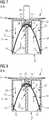
Die Dichtmembran ist vorzugsweise so im Auslasselement bzw. im Rohrstück angeordnet, dass die Dichtmembran in der Dichtstellung in einem Längsschnitt durch das Auslasselement näherungsweise eine in Richtung des Auslasselements geöffnete Parabel im Auslasselement ausbildet. Vorzugsweise fällt ein Ursprung der parabelartig gelagerten Dichtmembran mit einer Position der vorzugsweise konvexen Oberkante des zweiten Lagerelements zusammen. Die parabelartige Lagerung der Membran ergibt sich insbesondere bei einem Längsschnitt orthogonal zu einer Breite des zweiten Lagerelements. Dies wird nachfolgend beschrieben.The sealing membrane is preferably arranged in the outlet element or in the pipe section in such a way that the sealing membrane in the sealing position in a longitudinal section through the outlet element approximately forms a parabola open in the direction of the outlet element in the outlet element. An origin of the sealing membrane mounted in a parabolic manner preferably coincides with a position of the preferably convex upper edge of the second bearing element. The parabolic mounting of the membrane results in particular in the case of a longitudinal section orthogonal to a width of the second bearing element. This is described below.
Um die Dichtmembran nach der Art einer Parabel im Rohrstück zu lagern, kann das zweite Lagerelement, wie beschrieben, eine Klemmplatte sein, z.B. nach der Art eines flachen Quaders. Die Breite der Klemmplatte entspricht, wie gesagt, zumindest einem Innenquerschnitt des Rohrstücks. Vorzugsweise kann eine Tiefe bzw. Dicke der Klemmplatte (orthogonal zur Breite) um ein Vielfaches geringer als die Breite der Klemmplatte sein. Eine Länge der Klemmplatte entspricht demnach einer Ausdehnung der Klemmplatte in Längsrichtung der Geruchsverschlusseinrichtung. Dadurch, dass das zweite Lagerelement als flache Platte ausgebildet ist, bleibt ein Großteil des Innenquerschnitts des Rohrstücks für den Urinfluss frei. Das zweite Lagerelement bildet quasi eine „partielle Trennwand“ im Rohrstück und kann im Betrieb in Längsrichtung von zwei Seiten umströmt werden.In order to mount the sealing membrane in the pipe section in the manner of a parabola, the second bearing element can, as described, be a clamping plate, for example in the manner of a flat cuboid. As mentioned, the width of the clamping plate corresponds to at least an inner cross section of the pipe section. A depth or thickness of the clamping plate (orthogonal to the width) can preferably be several times less than the width of the clamping plate. A length of the clamping plate accordingly corresponds to an expansion of the clamping plate in the longitudinal direction of the odor trap device. Because the second bearing element is designed as a flat plate, a large part of the inner cross-section of the pipe section remains free for the flow of urine. The second bearing element forms a " partial partition ”in the pipe section and can be flowed around in the longitudinal direction from two sides during operation.
Vorzugsweise kann über die Tiefe und/oder die Breite des zweiten Lagerelements ein Kontaktbereich zwischen der Dichtmembran und dem zweiten Lagerelement definiert werden. Eine Breite des zweiten Lagerelements hängt u. a. von dem gewählten Rohrstück-Durchmesser ab und kann an der breitesten Stelle der Klemmplatte, z.B. im Bereich von Auswölbungen, z.B. weniger als 35mm, vorzugsweise weniger als 30mm und/oder zumindest 20mm, vorzugsweise zumindest 25mm sein, insbesondere 28mm. Dadurch, dass das zweite Lagerelement eine relativ geringe Dicke hat, insbesondere in Bezug auf die Breite des zweiten Lagerelements, kann die Dichtmembran dem zweiten Lagerelement „satteldeckenartig“ aufliegen.A contact area between the sealing membrane and the second bearing element can preferably be defined over the depth and / or the width of the second bearing element. A width of the second bearing element depends, inter alia. on the selected pipe section diameter and can be at the widest point of the clamping plate, e.g. in the area of bulges, e.g. less than 35mm, preferably less than 30mm and / or at least 20mm, preferably at least 25mm, in particular 28mm. Because the second bearing element has a relatively small thickness, in particular in relation to the width of the second bearing element, the sealing membrane can rest on the second bearing element in a “saddle-like manner”.
Eine Tiefe des zweiten Lagerelements kann z.B. nicht mehr als 5mm, vorzugsweise nicht mehr als 4mm und/oder zumindest 1mm, vorzugsweise zumindest 2mm, insbesondere 3mm sein. Eine Länge der Klemmplatte kann z.B. wenigstens 10mm, vorzugsweise wenigstens 15mm und/oder nicht mehr als 30mm, vorzugsweise nicht mehr als 25mm sein, insbesondere 20mm.A depth of the second bearing element can be, for example, not more than 5mm, preferably not more than 4mm and / or at least 1mm, preferably at least 2mm, in particular 3mm. A length of the clamping plate can, for example, be at least 10 mm, preferably at least 15 mm and / or not more than 30 mm, preferably not more than 25 mm, in particular 20 mm.
Das bedeutet, die Dichtmembran kann mit einem zentralen Bereich der Dichtmembran dem zweiten Lagerelement in einem Kontaktbereich, z.B. auf der konvexen Oberkante der Klemmplatte, aufliegen, wobei sich die Dichtmembran ausgehend vom zweiten Lagerelement bis zur Dichtwandung hin erstreckt. Vorzugsweise kann das zweite Lagerelement eine Art zentralen „Sattel“ (durch die abgerundete konvexe Oberkante gebildet) für die Dichtmembran bilden, der sich, wie gesagt, bevorzugt durch den gesamten Innenquerschnitt erstreckt.This means that the sealing membrane can rest with a central area of the sealing membrane on the second bearing element in a contact area, e.g. on the convex upper edge of the clamping plate, the sealing membrane extending from the second bearing element to the sealing wall. The second bearing element can preferably form a kind of central “saddle” (formed by the rounded convex upper edge) for the sealing membrane, which, as stated, preferably extends through the entire internal cross-section.
Für eine besonders sichere Lagerung der Dichtmembran kann eine einlassseitige Oberkante des zweiten Lagerelements bzw. der Klemmplatte eine, vorzugsweise konvex ausgebildete, Verdickung gegenüber der restlichen Klemmplatte haben. Vorzugsweise kann die Klemmplatte in einem Längsschnitt orthogonal zur Breite der Klemmplatte eine überwiegend pilzförmig ausgebildete Oberkante haben. Das bedeutet, der durch die Klemmplatte ausgebildete Sattel für die Dichtmembran kann bevorzugt im Wesentlichen pilzförmig sein. Bei dieser Ausgestaltung kann der Sattel eine Stärke von z.B. zumindest 4mm, vorzugsweise zumindest 5mm, bevorzugt zumindest 6mm und/oder nicht mehr als 11mm, vorzugsweise nicht mehr als 10mm haben, insbesondere 9mm.For a particularly secure mounting of the sealing membrane, an inlet-side upper edge of the second bearing element or the clamping plate can have a, preferably convex, thickening opposite the rest of the clamping plate. The clamping plate can preferably have a predominantly mushroom-shaped upper edge in a longitudinal section orthogonal to the width of the clamping plate. This means that the saddle formed by the clamping plate for the sealing membrane can preferably be essentially mushroom-shaped. In this embodiment, the saddle can have a thickness of, for example, at least 4mm, preferably at least 5mm, preferably at least 6mm and / or not more than 11mm, preferably not more than 10mm, in particular 9mm.
Bei einer derartigen bevorzugten Ausgestaltung der Klemmplatte mit einer, vorzugsweise konvexen, verstärkt ausgebildeten Oberkante (gegenüber der restlichen Klemmplatte), kann die Abstützung der Klemmplatte zum Rohrstück deutlich oberhalb des auslassseitigen Endbereichs der Dichtmembran erfolgen. Auf Grund der relativ (zur restlichen Klemmplatte) großen Tiefe im Bereich der Oberkante kann die Abstützung im Rohrstück dann nur im Bereich der Oberkante der Klemmplatte erfolgen. Beispielsweise kann sich die Klemmplatte dann nur mit den Randbereichen, insbesondere den Ecken, der Oberkante im Rohrstück abstützen. Das bedeutet, dass die übrigen Bereiche der Klemmplatte, z.B. die flächigen Seitenkanten der Klemmplatte, nicht oder nicht maßgeblich an der Abstützung beteiligt sind. D. h. die Abstützung der Klemmplatte erfolgt auf jeder Seite im Rohrstück (d.h. an zwei diametral gegenüberliegenden Abstützbereichen) jeweils an zwei Abstützpunkten, nämlich jeweils den Ecken der Oberkante der Klemmplatte. Beispielsweise könnte dann bereichsweise auch ein kleiner Spalt zwischen den Seitenkanten der Klemmplatte und der Innenwandung des Rohrstücks sein, da die Abstützung dann gezielt nur im Bereich der Oberkante des zweiten Lagerelements erfolgt. Bei dieser Ausgestaltung entsprechen die Abstützbereiche des Rohrstücks den definierten Bereichen der Innenwandung des Rohrstücks, in denen das zweite Lagerelement über die verstärkt ausgebildete Oberkante Kontakt zum Rohrstück hat.In such a preferred embodiment of the clamping plate with a preferably convex, reinforced upper edge (opposite the rest of the clamping plate), the clamping plate can be supported in relation to the pipe section well above the outlet-side end region of the sealing membrane. Due to the large depth in the area of the upper edge (relative to the rest of the clamping plate), the support in the pipe section can then only take place in the area of the upper edge of the clamping plate. For example, the clamping plate can then only be supported with the edge regions, in particular the corners, of the upper edge in the pipe section. This means that the remaining areas of the clamping plate, e.g. the flat side edges of the clamping plate, are not or not significantly involved in the support. I. E. The clamping plate is supported on each side in the pipe section (i.e. on two diametrically opposite support areas) at two support points, namely at the corners of the upper edge of the clamping plate. For example, there could then also be a small gap in some areas between the side edges of the clamping plate and the inner wall of the pipe section, since the support then takes place specifically only in the area of the upper edge of the second bearing element. In this embodiment, the support areas of the pipe section correspond to the defined areas of the inner wall of the pipe section in which the second bearing element is in contact with the pipe section via the reinforced upper edge.
Bevorzugt kann sich die Dichtmembran überwiegend orthogonal zu einer Längserstreckung des Sattels (entspricht der Breite des zweiten Lagerelements) zu beiden Seiten des Sattels in Richtung eines Endbereichs des Auslasselements (Auslassende) bis zur Dichtwandung des Rohrstücks hin erstrecken.The sealing membrane can preferably extend predominantly orthogonally to a longitudinal extension of the saddle (corresponds to the width of the second bearing element) on both sides of the saddle in the direction of an end region of the outlet element (outlet end) up to the sealing wall of the pipe section.
Besonders bevorzugt kann die Dichtmembran so angeordnet sein, dass die Dichtmembran in einem Bereich zwischen dem Sattel und der Dichtwandung einen (Neigungs-)Winkel von nicht mehr als 50° in Bezug auf eine Längserstreckung bzw. Längsachse des Rohrstücks bildet, insbesondere in Bezug auf die Lotrichtung. Der Winkel entspricht einem (Innen-)Winkel zwischen dem zweiten Lagerelement und einer Auslassseite der Dichtmembran. Der Winkel kann kleiner als 45°, vorzugsweise kleiner als 35°, bevorzugt kleiner als 30°, besonders bevorzugt kleiner als 25° sein. Vorzugsweise kann der Winkel mindestens 20° sein.Particularly preferably, the sealing membrane can be arranged such that the sealing membrane in an area between the saddle and the sealing wall forms an (inclination) angle of not more than 50 ° with respect to a longitudinal extension or longitudinal axis of the pipe section, in particular with respect to the Plumb direction. The angle corresponds to an (inner) angle between the second bearing element and an outlet side of the sealing membrane. The angle can be smaller than 45 °, preferably smaller than 35 °, preferably smaller than 30 °, particularly preferably smaller than 25 °. Preferably the angle can be at least 20 °.
Insbesondere kann die Dichtmembran so im Auslasselement angeordnet sein, dass durch die Dichtmembran und die Dichtwandung zwei vertikale, in einer Längsrichtung des Rohrstücks verlaufende Einlauftrichter ausbildet sind. Je nach konkreter Ausgestaltung der Dichtwandung kann ein jeweiliger Einlauftrichter auch durch die Dichtmembran, die Dichtwandung und durch die Innenwandung des Rohrstücks gebildet sein. Insbesondere sofern die Dichtwandung mit einer später noch beschriebenen Dichtlippe ausgebildet ist, kann ein Einlauftrichter auch nur durch die Dichtmembran und die Innenwandung des Rohrstücks gebildet sein.In particular, the sealing membrane can be arranged in the outlet element in such a way that the sealing membrane and the sealing wall form two vertical inlet funnels running in a longitudinal direction of the pipe section. Depending on the specific design of the sealing wall, a respective inlet funnel can also be formed by the sealing membrane, the sealing wall and by the inner wall of the pipe section. In particular, provided the sealing wall with one to be described later Sealing lip is formed, an inlet funnel can also be formed only by the sealing membrane and the inner wall of the pipe section.
Ungeachtet der konkreten Ausgestaltung kann vorzugsweise zu beiden Seiten des Sattels, bezogen auf dessen Längserstreckung, jeweils ein Einlauftrichter für Urin ausgebildet sein. Bevorzugt verjüngt sich ein jeweiliger Einlauftrichter in Längsrichtung zum Endbereich bzw. zum Auslassende des Auslasselements hin. Insbesondere kann ein jeweiliger Einlauftrichter in einem auslassseitigen Endbereich des Einlauftrichters spitzwinklig zulaufen. Unter „auslassseitig“ wird im Rahmen der Anmeldung allgemein eine Richtung verstanden, die zum Auslasselement, insbesondere zu einem Endbereich bzw. Auslassende des Auslasselements hin weist. Entsprechend wird unter „einlassseitig“ allgemein eine Richtung verstanden, die in Richtung auf das Einlasselement hin weist, insbesondere in Richtung der Eintrittsseite des Einlasselements.Regardless of the specific configuration, an inlet funnel for urine can preferably be formed on both sides of the saddle, based on its longitudinal extension. A respective inlet funnel preferably tapers in the longitudinal direction towards the end region or towards the outlet end of the outlet element. In particular, a respective inlet funnel can taper at an acute angle in an outlet-side end region of the inlet funnel. In the context of the application, “outlet side” is generally understood to mean a direction which points towards the outlet element, in particular towards an end region or outlet end of the outlet element. Correspondingly, “inlet side” is generally understood to mean a direction which points in the direction of the inlet element, in particular in the direction of the inlet side of the inlet element.
Für einen möglichst gleichmäßigen Füllgrad der beiden Einlauftrichter, kann das Einlasselement zumindest zwei, vorzugsweise schlitzartige, Eintrittsöffnungen ausbilden. Bevorzugt ist jeweils eine Eintrittsöffnung einem der beiden Einlauftrichter zugeordnet. Vorzugsweise können die beiden Einlaufschlitze durch einen dazwischen angeordneten „Materialsteg“ voneinander getrennt sein. Dieser Steg kann, wie beschrieben, das erste Lagerelement bilden. Bevorzugt kann der Steg ein Kopplungselement, beispielsweise einen Einsteckzapfen, für einen Duftspender und/oder ein Montagewerkzeug aufweisen. Dies wird später noch beschrieben.To ensure that the two inlet funnels are filled as evenly as possible, the inlet element can form at least two, preferably slot-like, inlet openings. One inlet opening is preferably assigned to one of the two inlet funnels. The two inlet slots can preferably be separated from one another by a “material web” arranged in between. As described, this web can form the first bearing element. The web can preferably have a coupling element, for example a plug-in pin, for a fragrance dispenser and / or an assembly tool. This will be described later.
Vorteilhafterweise kann mittels der Einlauftrichter das Urin oberhalb (also einlassseitig) der Dichtmembran gezielt so aufgestaut werden, dass das Urin nur vor einer relativ kleinen Teilfläche der Dichtmembran ansteht. Die Flüssigkeit wird also auf eine sehr geringe Fläche der Dichtmembran konzentriert. Dadurch kann auch bei geringen Flüssigkeitsvolumina oberhalb der Dichtmembran ein vergleichsweise großer Schweredruck auf die Dichtmembran aufgebaut werden, so dass die Dichtmembran auch bei geringen Volumina in die Öffnungsstellung bewegt werden kann. In der Folge verbleibt nach dem Schließen der Dichtmembran auch weniger Flüssigkeit oberhalb der Dichtmembran, was einer Geruchsbildung weiter entgegenwirkt. Dies ist ein Vorteil gegenüber bekannten Dichtmembranen, bei denen die Dichtmembran der Dichtwandung flächig und im Wesentlichen horizontal umlaufend anliegt, so dass mehr Flüssigkeit aber verteilt auf eine größere Oberfläche aufgestaut wird, was eine Geruchsbildung begünstigen kann.Advantageously, the urine above (that is to say on the inlet side) of the sealing membrane can be dammed up in a targeted manner by means of the inlet funnel in such a way that the urine is only present in front of a relatively small partial area of the sealing membrane. The liquid is therefore concentrated on a very small area of the sealing membrane. As a result, a comparatively high gravity pressure can be built up on the sealing membrane above the sealing membrane even with small volumes of liquid, so that the sealing membrane can be moved into the open position even with small volumes. As a result, after the sealing membrane is closed, less liquid remains above the sealing membrane, which further counteracts the formation of odors. This is an advantage over known sealing membranes, in which the sealing membrane of the sealing wall rests flat and essentially horizontally circumferentially, so that more liquid is dammed but distributed over a larger surface, which can promote the formation of odors.
Um die Dichtwirkung der Geruchsverschlusseinrichtung weiter zu verbessern, kann eine Dichtwandung des Rohrstücks zumindest abschnittsweise eine gegenüber der restlichen Innenwandung des Rohrstücks nach innen vorstehende Dichtlippe ausbilden, wobei dann die Dichtfunktion im Wesentlichen über die Dichtlippe erfolgt. Besonders bevorzugt kann die Dichtlippe in einem Längsschnitt durch das Auslasselement näherungsweise eine in Richtung des Auslasselements geöffnete Parabel im Auslasselement ausbilden.In order to further improve the sealing effect of the odor trap device, a sealing wall of the pipe section can form, at least in sections, a sealing lip protruding inwardly relative to the remaining inner wall of the pipe section, the sealing function then essentially taking place via the sealing lip. Particularly preferably, in a longitudinal section through the outlet element, the sealing lip can approximately form a parabola open in the direction of the outlet element in the outlet element.
Vorzugsweise kann die Dichtmembran so angeordnet sein, dass die Dichtmembran in der Dichtstellung an einer vom Einlasselement abgewandten Seite der Dichtlippe anliegt. Mit anderen Worten kann die Dichtmembran der Dichtlippe in der Dichtstellung auslassseitig anliegen.The sealing membrane can preferably be arranged in such a way that, in the sealing position, the sealing membrane rests on a side of the sealing lip facing away from the inlet element. In other words, the sealing membrane of the sealing lip can rest on the outlet side in the sealing position.
Bevorzugt kann die Dichtmembran eine Eigenspannung haben (da sie dazu neigt, wieder eine flache Ausgangsform anzunehmen, wenn sie nicht „zwangsweise“, z.B. durch die Lagerelemente, in eine bestimmte Form gebogen wird), so dass die Dichtmembran in der Dichtstellung von selbst „federnd“ an der Dichtlippe dichtend anliegt.The sealing membrane can preferably have an internal stress (since it tends to take on a flat initial shape again if it is not "forcibly" bent into a certain shape, e.g. by the bearing elements), so that the sealing membrane is automatically "resilient" in the sealing position “Is in sealing contact with the sealing lip.
Vorteilhafterweise kann die Dichtmembran im Zusammenspiel mit der Dichtlippe (als Dichtwandung) eine Art„Dichtring“ ausbilden. Anders als bei bekannten Dichtmembranen, bei denen eine relativ große Membranfläche als „Dichtfläche“ nötig ist, mit der die Dichtmembran an der Dichtwandung anliegt, kann hier die Konstruktion und der Materialaufwand der Dichtmembran weiter vereinfacht bzw. reduziert werden. Weiterhin vorteilhaft kann durch die Dichtlippe erreicht werden, dass die Dichtmembran besonders zuverlässig in der Dichtstellung angeordnet ist. Somit kann beispielsweise bei einem Druckstoß von Gas aus der Kanalisation ein unerwünschtes Öffnen bzw. Nachgeben der Dichtmembran verhindert werden, da die Dichtlippe in Richtung des Einlasselements eine Art Gegenlager für die Dichtmembran bildet.The sealing membrane can advantageously form a type of “ sealing ring” in interaction with the sealing lip (as a sealing wall). In contrast to known sealing membranes, in which a relatively large membrane surface is required as a "sealing surface" with which the sealing membrane rests against the sealing wall, the construction and the cost of materials for the sealing membrane can be further simplified or reduced. The sealing lip can also advantageously ensure that the sealing membrane is arranged particularly reliably in the sealing position. In this way, for example, in the event of a gas surge from the sewer system, undesired opening or yielding of the sealing membrane can be prevented, since the sealing lip forms a kind of counter-bearing for the sealing membrane in the direction of the inlet element.
Um die Geruchsverschlusseinrichtung noch effektiver zu gestalten, kann zumindest ein Teil einer Oberfläche der Dichtwandung des Rohrstücks, insbesondere im Bereich der Dichtlippe, zumindest abschnittsweise eine Anzahl von Erhebungen und/oder Vertiefungen haben. Vorzugsweise sind zwei oder mehr Erhebungen und/oder Vertiefungen in Längsrichtung des Rohrstücks im Bereich der Dichtlippe angeordnet. Bevorzugt kann eine Anzahl von regelmäßig angeordneten rillenartigen Ausnehmungen und/oder Ausstülpungen die Dichtlippe in Längsrichtung des Rohrstücks durchziehen.In order to make the odor trap device even more effective, at least part of a surface of the sealing wall of the pipe section, in particular in the area of the sealing lip, can have a number of elevations and / or depressions, at least in sections. Two or more elevations and / or depressions are preferably arranged in the longitudinal direction of the pipe section in the area of the sealing lip. A number of regularly arranged groove-like recesses and / or protuberances can preferably pull through the sealing lip in the longitudinal direction of the pipe section.
Vorteilhafterweise kann dadurch ein Verkleben der Dichtmembran mit der Dichtlippe verhindert werden, beispielsweise, wenn das Trockenurinal längere Zeit nicht in Benutzung war. Zwar kann die Wahrscheinlichkeit eines Verklebens gegenüber bekannten Geruchsverschlusseinrichtungen bereits durch die Ausbildung eines „Dichtrings“ reduziert werden, da ja bereits dadurch eine Kontaktfläche zwischen Dichtmembran und Dichtwandung erheblich reduziert werden kann. Weiterhin kann auch über die besonderen Einlauftrichter am auslassseitigen Endbereich der Einlauftrichter durch ein gezieltes Aufstauen von Flüssigkeit lokal ein relativ großer Druck auf die Membran aufgebaut werden, was im Falle eines Verklebens der Membran ein Öffnen der Dichtmembran unterstützen kann. Allerdings kann durch die Anordnung von Rillen und/oder Vorsprüngen die Gefahr eines Verklebens noch weiter verringert werden. Bevorzugt sind die Rillen und/oder Erhebungen so dimensioniert, dass in der Dichtstellung der Membran ein Austreten von Gasen aus dem Abfluss weitestgehend verhindert wird.This advantageously prevents the sealing membrane from sticking to the sealing lip, for example if the dry urinal has not been used for a long time. Although it can the likelihood of sticking compared to known odor trap devices can already be reduced by the formation of a "sealing ring", since this alone can considerably reduce a contact area between the sealing membrane and the sealing wall. Furthermore, a relatively high pressure can be built up locally on the membrane via the special inlet funnel at the outlet end area of the inlet funnel through a targeted damming up of liquid, which can support the opening of the sealing membrane in the event of the membrane sticking. However, the arrangement of grooves and / or projections can further reduce the risk of sticking. The grooves and / or elevations are preferably dimensioned in such a way that, in the sealing position of the membrane, an escape of gases from the drain is largely prevented.
Besonders bevorzugt kann eine Anzahl von Erhebungen und/oder Vertiefungen nur in einem auslassseitigen, vorzugsweise im spitzwinklig zulaufenden, Endbereich eines jeweiligen Einlauftrichters ausgebildet sein. Mit anderen Worten können die Erhebungen und/oder Vertiefungen nur in einem definierten Teilbereich der Dichtwandung angeordnet sein, in welchem Teilbereich der auslassseitige Endbereich der Dichtmembran in Kontakt mit der Dichtwandung ist. Vorteilhafterweise kann damit ein Verkleben der Membran verhindert werden, wobei ein Austreten von Gasen noch besser verhindert werden kann.Particularly preferably, a number of elevations and / or depressions can be formed only in an outlet-side, preferably in the acute-angled, end region of a respective inlet funnel. In other words, the elevations and / or depressions can only be arranged in a defined sub-area of the sealing wall, in which sub-area the outlet-side end area of the sealing membrane is in contact with the sealing wall. This can advantageously prevent the membrane from sticking, with the escape of gases being able to be prevented even better.
Die Dichtmembran kann vor einer Montage im Auslasselement, wie beschrieben, vorzugsweise eine im Wesentlichen planare bzw. flächige Grundfläche haben. Unter der Grundfläche der Dichtmembran wird eine Fläche mit der größten flächenmäßigen Ausdehnung der Membran verstanden. Das bedeutet, dass im Betrieb der Geruchsverschlusseinrichtung die Fläche der Einlassseite der Dichtmembran und die Fläche der Auslassseite der Dichtmembran vorzugsweise jeweils der Grundfläche entsprechen.As described, the sealing membrane can preferably have an essentially planar or flat base surface before it is installed in the outlet element. The base area of the sealing membrane is understood to mean an area with the largest areal extension of the membrane. This means that when the odor trap device is in operation, the area of the inlet side of the sealing membrane and the area of the outlet side of the sealing membrane preferably each correspond to the base area.
Bevorzugt kann die Grundfläche der Dichtmembran eine überwiegend ellipsenartige Außenkontur haben. Die Abmessungen der Ellipse hängen u. a. von dem gewählten Rohrstück-Durchmesser ab. Die Nebenachse der Ellipse entspricht vorzugsweise in etwa dem Innendurchmesser des Rohrstücks, die Hauptachse entspricht vorzugsweise mindestens dem 1,5-fachen, besonders bevorzugt dem 2-fachen, des Durchmessers des Rohrstücks und/oder maximal dem 3-fachen, besonders bevorzugt dem 2,5-fachen, des Innendurchmessers des Rohrstücks. Als Materialien für die Dichtmembran können z.B. Silikone bzw. Mischungen verschiedener Silikone verwendet werden, insbesondere Silikonelastomere. Bevorzugt kann die Dichtmembran mittels eines Stanzverfahrens in Form einer gepuderten Silikonmembran hergestellt werden, wobei vorteilhafterweise auf ein vergleichsweise aufwendiges Spritzverfahren verzichtet werden kann.The base area of the sealing membrane can preferably have a predominantly elliptical outer contour. The dimensions of the ellipse depend on, among other things. on the selected pipe section diameter. The minor axis of the ellipse preferably corresponds approximately to the inside diameter of the pipe section, the main axis preferably corresponds to at least 1.5 times, particularly preferably 2 times, the diameter of the pipe section and / or a maximum of 3 times, particularly preferably 2, 5 times the inner diameter of the pipe section. For example, silicones or mixtures of different silicones, in particular silicone elastomers, can be used as materials for the sealing membrane. The sealing membrane can preferably be produced in the form of a powdered silicone membrane by means of a stamping process, in which case a comparatively complex injection molding process can advantageously be dispensed with.
Vorzugsweise kann die Dichtmembran innerhalb ihrer Außenkontur vollflächig ausgebildet sein. Insbesondere kann die Dichtmembran innerhalb der Außenkontur beschädigungsfrei bzw. unterbrechungsfrei ausgebildet sein. Bevorzugt ist die Dichtmembran innerhalb der Außenkontur hohlraumfrei ausgebildet.The sealing membrane can preferably be formed over the entire surface within its outer contour. In particular, the sealing membrane can be designed without damage or interruption within the outer contour. The sealing membrane is preferably designed without cavities within the outer contour.
Wie eingangs beschrieben, kann auf Grund der besonderen Halterung eine relativ einfach aufgebaute Dichtmembran in der Geruchsverschlusseinrichtung verwendet werden. Vorteilhafterweise muss die Dichtmembran also nicht in einer besonderen geometrischen Form produziert werden, sondern sie kann im Wesentlichen flach ausgebildet sein. Auch benötigt die Dichtmembran zur Halterung keine Löcher, Fortsätze oder sonstige Befestigungsmittel. Auch dadurch können die Herstellungskosten weiter reduziert werden.As described at the beginning, due to the special holder, a relatively simply constructed sealing membrane can be used in the odor trap device. Advantageously, the sealing membrane does not have to be produced in a special geometric shape, but can be designed to be essentially flat. The sealing membrane also does not require any holes, extensions or other fastening means for mounting. This also allows the manufacturing costs to be reduced further.
Vorzugsweise kann das Einlasselement einen vom Auslasselement wegweisenden Einsteckzapfen zur Kopplung eines Duftspenders und/oder eines Montagewerkzeugs zur Montage der Geruchsverschlusseinrichtung umfassen. Vorzugsweise kann der Einsteckzapfen als Kopplungselement durch Stoffschluss mit dem Einlasselement verbunden sein. Beispielsweise können der Zapfen und das Einlasselement mittels eines Spritzgussverfahrens als ein einziges Bauteil hergestellt werden. Der Einsteckzapfen kann bevorzugt zentral bzw. mittig auf der Eintrittsseite des Einlasselements angeordnet sein. Besonders bevorzugt kann der Zapfen auf einem Steg, welcher das erste Lagerelement bilden kann, zwischen zwei Eintrittsöffnungen des Einlasselements angeordnet sein.The inlet element can preferably comprise an insertion pin pointing away from the outlet element for coupling a fragrance dispenser and / or an assembly tool for assembling the odor trap device. The insertion pin can preferably be connected as a coupling element to the inlet element by means of a material connection. For example, the pin and the inlet element can be manufactured as a single component by means of an injection molding process. The insertion pin can preferably be arranged centrally or centrally on the inlet side of the inlet element. Particularly preferably, the pin can be arranged on a web, which can form the first bearing element, between two inlet openings of the inlet element.
Um die Stabilität der Geruchsverschlusseinrichtung weiter zu erhöhen, insbesondere bei einer Montage bzw. Demontage im Trockenurinal, können im Einlasselement auch zwei Materialstege ausgebildet sein, die sich quer zueinander über bzw. in der Einlassöffnung erstrecken. Vorzugsweise können die beiden Stege orthogonal zueinander angeordnet sein und sich in einem Mittelpunkt des Einlasselements schneiden. Dadurch werden im Einlasselement vier Eintrittsöffnungen für Urin ausgebildet. Bevorzugt kann in einem Schnittpunkt der beiden Stege ein Kopplungselement (z.B. ein Zapfen) für die Duftkappe und/oder ein Montagwerkzeug angeordnet sein.In order to further increase the stability of the odor trap device, in particular during assembly or disassembly in the dry urinal, two material webs can also be formed in the inlet element, which extend transversely to one another over or in the inlet opening. The two webs can preferably be arranged orthogonally to one another and intersect at a center point of the inlet element. As a result, four inlet openings for urine are formed in the inlet element. A coupling element (e.g. a pin) for the scent cap and / or an assembly tool can preferably be arranged at an intersection of the two webs.
Besonders bevorzugt können ein Kopplungselement (z.B. der Zapfen) der Geruchsverschlusseinrichtung zur Befestigung des Duftspenders und ein Kopplungselement des Duftspenders für ein Montagewerkzeug im Wesentlichen identisch bzw. baugleich ausgebildet sein. Vorteilhafterweise kann dann mittels nur eines Montagewerkzeugs die Geruchsverschlusseinrichtung allein oder in Kombination mit dem daran gekoppelten Duftspender oder auch nur der Duftspender (an die Geruchsverschlusseinrichtung) montiert werden.A coupling element (for example the pin) of the odor trap device for fastening the fragrance dispenser and a coupling element of the fragrance dispenser for an assembly tool can be essentially identical or structurally identical. Advantageously, the odor trap device can then be mounted alone or in combination with the scent dispenser coupled to it, or even just the scent dispenser (on the odor trap device) by means of just one assembly tool.
Vorteilhafterweise kann über die Kopplung eines Montagewerkzeugs an den Einsteckzapfen einerseits ein einfaches und hygienisches Auswechseln der kartuschenartigen Geruchsverschlusseinrichtung ermöglicht werden. Andererseits kann der Einsteckzapfen im Betrieb der Geruchsverschlusseinrichtung zur Anbringung des Duftspenders genutzt werden, um die Benutzung des Trockenurinals noch angenehmer zu gestalten.Advantageously, on the one hand, a simple and hygienic exchange of the cartridge-like odor trap device can be made possible by coupling an assembly tool to the insertion pin. On the other hand, the insertion pin can be used to attach the fragrance dispenser when the odor trap device is in operation, in order to make the use of the dry urinal even more pleasant.
Die Erfindung wird im Folgenden unter Hinweis auf die beigefügten Figuren anhand von Ausführungsbeispielen noch einmal näher erläutert. Dabei sind in den verschiedenen Figuren gleiche Komponenten mit identischen Bezugsziffern versehen. Die Figuren sind in der Regel nicht maßstäblich. Es zeigen:
1 bis4 schematische, teils perspektivische Ansichten von unterschiedlichen Ausführungsformen einer Geruchsverschlusseinrichtung,5 und6 Untersichten von zwei unterschiedlichen Ausführungsformen einer Geruchsverschlusseinrichtung,7 bis 9 Schnittzeichnungen von unterschiedlichen Ausführungsformen einer Geruchsverschlusseinrichtung,10 eine weitere Schnittzeichnung einer Ausführungsform einer Geruchsverschlusseinrichtung,11 eine schematische Ansicht einer Klemmpatte als zweites Lagerelement,12 eine schematische Ansicht einer Dichtmembran,13 und 14 schematische, teils perspektivische Ansichten einer weiteren Ausführungsform einer Geruchsverschlusseinrichtung,15 eine perspektivische Ansicht eines Urinaleinsatzes,16 eine Untersicht eines Duftspenders.
1 until4th schematic, partly perspective views of different embodiments of an odor trap device,5 and6th Bottom views of two different embodiments of an odor trap device,7th until9 Sectional drawings of different embodiments of an odor trap device,10 a further sectional drawing of an embodiment of an odor trap device,11th a schematic view of a clamping plate as a second bearing element,12th a schematic view of a sealing membrane,13th and14th schematic, partly perspective views of a further embodiment of an odor trap device,15th a perspective view of a urinal insert,16 a bottom view of a fragrance dispenser.
In den
Die Geruchsverschlusseinrichtung
Das Einlasselement
Da der grundsätzliche Aufbau von kartuschenartigen Geruchsverschlusseinrichtungen und deren Montage bzw. Demontage in einem Trockenurinal allgemein bekannt ist, werden nachfolgend nur solche Merkmale der Geruchsverschlusseinrichtung
Die Oberfläche
Die Eintrittsschlitze
Im Schnittpunkt der beiden Stege
Jeweils zwei Eintrittsschlitze
Die Zuordnung der Eintrittsschlitze
Die Geruchsverschlusseinrichtung
Wie
Die Stege
Der Unterschied zwischen den Ausführungsformen der
Ungeachtet der konkreten Anordnung weist der Einsteckzapfen
Die Dichtlippe
Die Halterung der Membran
Wie in
Zur Halterung ist die Membran
Weiterhin ist erkennbar, dass die konkave Form des ersten Lagerelements
Der schichtweise Aufbau der Halterung ergibt sich also durch eine erste hier obenliegende Schicht
Die Klemmplatte
Zur Befestigung im Rohrstück
In
Der Steg
Zur Abstützung hat das zweite Lagerelement
Das zweite Lagerelement
Diese besondere Anordnung wird auch in
Für eine zuverlässige Befestigung der Klemmplatte
Wie bereits anhand der
Quer zur Längserstreckung des Sattels erstreckt sich die Membran
Das zweite Lagerelement
Um ein Verkleben der Membran
Im Unterschied zu
In den
Im Unterschied zum Ausführungsbeispiel aus
In
In
Die Membran
In
In
Es wird abschließend noch einmal darauf hingewiesen, dass es sich bei den vorhergehend detailliert beschriebenen Geruchsverschlusseinrichtungen lediglich um Ausführungsbeispiele handelt, welche vom Fachmann in verschiedenster Weise modifiziert werden können, ohne den Bereich der Erfindung zu verlassen. So sind beispielsweise die in den jeweiligen Ausführungsbeispielen gezeigten Stege und/oder Kopplungselemente untereinander beliebig austauschbar und/oder kombinierbar. Weiterhin kann die Geruchsverschlusseinrichtung geeignete, in den zuvor gezeigten Ausführungsbeispielen nicht beschriebene, Mittel zur Montage in einem Abfluss und/oder Dichtelemente umfassen. Weiterhin schließt die Verwendung der unbestimmten Artikel „ein“ bzw. „eine“ nicht aus, dass die betreffenden Merkmale auch mehrfach vorhanden sein können.Finally, it is pointed out once again that the odor trap devices described in detail above are merely exemplary embodiments which can be modified in the most varied of ways by the person skilled in the art without departing from the scope of the invention. For example, the webs and / or coupling elements shown in the respective exemplary embodiments can be exchanged and / or combined with one another as required. Furthermore, the odor trap device can comprise suitable means for mounting in a drain and / or sealing elements not described in the exemplary embodiments shown above. Furthermore, the use of the indefinite article “a” or “an” does not exclude the possibility that the relevant characteristics can also be present more than once.
BezugszeichenlisteList of reference symbols
- 11
- GeruchsverschlusseinrichtungOdor trap device
- 22
- EinlasselementInlet element
- 33
- Auslasselement / RohrstückOutlet element / pipe section
- 44th
- Dichtmembran (in
5 bis10 ,12 )Sealing membrane (in5 until10 ,12th ) - 55
- Erstes Lagerelement (in
7 bis10 )First bearing element (in7th until10 ) - 66th
- Zweites Lagerelement / KlemmplatteSecond bearing element / clamping plate
- 6'6 '
- Auswölbung / NaseBulge / nose
- 77th
- DichtwandungSealing wall
- 88th
- Erste Seite Membran / EinlassseiteFirst membrane / inlet side
- 99
- Zweite Seite Membran / AuslassseiteSecond membrane / outlet side
- 10, 10'10, 10 '
- Kontaktfläche (zweites Lagerelement)Contact surface (second bearing element)
- 1212th
- Endbereich (Dichtmembran)End area (sealing membrane)
- 13, 13'13, 13 '
- EinlauftrichterInlet funnel
- 1414th
- Dichtlippe / DichtwandungSealing lip / sealing wall
- 1515th
- Erhebung (Dichtwandung)Elevation
- 1616
- Vertiefung (Dichtwandung)Recess (sealing wall)
- 1717th
- Außenkontur MembranOuter contour of the membrane
- 1818th
- Einsteckzapfen (Einlasselement) / KopplungselementInsertion pin (inlet element) / coupling element
- 1919th
- Hinterschneidung (Bajonettverschluss)Undercut (bayonet lock)
- 20, 20'20, 20 '
- Stegweb
- 21, 21', 21'', 21'''21, 21 ', 21' ', 21' ''
- EinlaufschlitzInlet slot
- 2222nd
- Innenwandung (Rohrstück)Inner wall (pipe section)
- 2323
- Eintrittsseite (Einlasselement)Inlet side (inlet element)
- 2424
- Randbereich (Einlasselement)Edge area (inlet element)
- 25, 25'25, 25 '
- Abstützbereich (Rohrstück)Support area (pipe section)
- 2626th
- Sattelsaddle
- 2727
- Auslassende (Auslasselement)Outlet end (outlet element)
- 2828
- Oberkante (zweites Lagerelement)Upper edge (second bearing element)
- 4040
- DuftspenderFragrance dispenser
- 4141
- Ausnehmung (Duftspender) / KopplunsgelementRecess (fragrance dispenser) / coupling element
- 4242
- UrinaleinsatzUrinal insert
- 4343
- Setset
- 4444
- Zapfen (Duftspender)Cones (fragrance dispenser)
- B1B1
- Durchmesser (Rohrstück)Diameter (pipe section)
- B2B2
- Breite (zweites Lagerelement)Width (second bearing element)
- SRSR
- Strömungsrichtung (Urin)Flow direction (urine)
- TT
- Tiefe / Stärke (Dichtmembran)Depth / thickness (sealing membrane)
Claims (15)
Translated fromGermanPriority Applications (3)
| Application Number | Priority Date | Filing Date | Title |
|---|---|---|---|
| DE102020114552.7ADE102020114552A1 (en) | 2020-05-29 | 2020-05-29 | Odor trap device for urinals |
| PCT/EP2021/064453WO2021240000A2 (en) | 2020-05-29 | 2021-05-28 | Odour trap device for urinals |
| EP21730528.3AEP4158115A2 (en) | 2020-05-29 | 2021-05-28 | Odour trap device for urinals |
Applications Claiming Priority (1)
| Application Number | Priority Date | Filing Date | Title |
|---|---|---|---|
| DE102020114552.7ADE102020114552A1 (en) | 2020-05-29 | 2020-05-29 | Odor trap device for urinals |
Publications (1)
| Publication Number | Publication Date |
|---|---|
| DE102020114552A1true DE102020114552A1 (en) | 2021-12-02 |
Family
ID=76305901
Family Applications (1)
| Application Number | Title | Priority Date | Filing Date |
|---|---|---|---|
| DE102020114552.7APendingDE102020114552A1 (en) | 2020-05-29 | 2020-05-29 | Odor trap device for urinals |
Country Status (3)
| Country | Link |
|---|---|
| EP (1) | EP4158115A2 (en) |
| DE (1) | DE102020114552A1 (en) |
| WO (1) | WO2021240000A2 (en) |
Citations (6)
| Publication number | Priority date | Publication date | Assignee | Title |
|---|---|---|---|---|
| US2675823A (en) | 1949-09-07 | 1954-04-20 | Jesse D Langdon | Backflow preventer |
| US5518026A (en) | 1994-09-30 | 1996-05-21 | G. T. Products, Inc. | Filler neck butterfly check valve |
| US20120192950A1 (en) | 2011-01-31 | 2012-08-02 | Kevin Dean Huber | Floor drain valve with resiliently mounted rigid flappers |
| DE102011085867A1 (en) | 2011-11-07 | 2013-05-08 | Tece Gmbh | trap |
| WO2015024965A1 (en) | 2013-08-21 | 2015-02-26 | Geberit International Ag | Odour-trap device |
| CN105040802A (en) | 2015-08-28 | 2015-11-11 | 宁波伊迷莎卫浴阀门有限公司 | High-water-seal overflowing preventing floor drain |
Family Cites Families (10)
| Publication number | Priority date | Publication date | Assignee | Title |
|---|---|---|---|---|
| DE29503980U1 (en)* | 1995-03-08 | 1995-05-04 | Hock, Hans Joachim, 67269 Grünstadt | Fragrance dispenser |
| KR200154243Y1 (en)* | 1997-02-11 | 1999-08-02 | 양재호 | Drainage trap attached to odour seals |
| KR200265950Y1 (en)* | 2001-11-27 | 2002-02-25 | 이승준 | A drainageway |
| US8943619B2 (en)* | 2011-06-17 | 2015-02-03 | Jose Romero | Trap assembly for a hybrid wall urinal and associated methods |
| US9556964B2 (en)* | 2014-04-22 | 2017-01-31 | Nws Europa Gmbh | Gravity drain valve |
| US9657854B2 (en)* | 2015-01-28 | 2017-05-23 | Green Drain, Inc. | Sliding skirt valve |
| DE102017108125A1 (en)* | 2017-04-13 | 2018-10-18 | Swiss Invent Ag | Valve system with adhesive protection |
| PT3434840T (en)* | 2017-07-24 | 2020-02-14 | Viega Tech Gmbh & Co Kg | Odour closure device for sanitary fixtures, in particular urinals |
| US20200224397A1 (en)* | 2019-01-11 | 2020-07-16 | Tnt Products, Llc | Drain sealing apparatus |
| US11408160B2 (en)* | 2019-04-09 | 2022-08-09 | Falcon Water Technologies, LLC | Reslient fluid control valve above drainage plane |
- 2020
- 2020-05-29DEDE102020114552.7Apatent/DE102020114552A1/enactivePending
- 2021
- 2021-05-28WOPCT/EP2021/064453patent/WO2021240000A2/ennot_activeCeased
- 2021-05-28EPEP21730528.3Apatent/EP4158115A2/enactivePending
Patent Citations (6)
| Publication number | Priority date | Publication date | Assignee | Title |
|---|---|---|---|---|
| US2675823A (en) | 1949-09-07 | 1954-04-20 | Jesse D Langdon | Backflow preventer |
| US5518026A (en) | 1994-09-30 | 1996-05-21 | G. T. Products, Inc. | Filler neck butterfly check valve |
| US20120192950A1 (en) | 2011-01-31 | 2012-08-02 | Kevin Dean Huber | Floor drain valve with resiliently mounted rigid flappers |
| DE102011085867A1 (en) | 2011-11-07 | 2013-05-08 | Tece Gmbh | trap |
| WO2015024965A1 (en) | 2013-08-21 | 2015-02-26 | Geberit International Ag | Odour-trap device |
| CN105040802A (en) | 2015-08-28 | 2015-11-11 | 宁波伊迷莎卫浴阀门有限公司 | High-water-seal overflowing preventing floor drain |
Also Published As
| Publication number | Publication date |
|---|---|
| WO2021240000A2 (en) | 2021-12-02 |
| EP4158115A2 (en) | 2023-04-05 |
| WO2021240000A3 (en) | 2022-03-31 |
Similar Documents
| Publication | Publication Date | Title |
|---|---|---|
| DE69923775T2 (en) | liquid dispenser | |
| EP1472419B1 (en) | Dispensing device for dispensing an active fluid into the flushing water in a toilet basin | |
| EP2840191B1 (en) | Odour trap device | |
| WO2006136215A2 (en) | Flushing water guiding arrangement for a toilet bowl | |
| WO2011098253A1 (en) | Jet regulator | |
| DE202018006705U1 (en) | flush toilet | |
| EP2217766B1 (en) | Flush water unit for a toilet bowl | |
| EP1447485B1 (en) | Draining device | |
| EP1780343B1 (en) | Sanitary flushing assembly comprising a device for adding a cleaning agent and/or a fragrance | |
| EP3543412B1 (en) | Flushing distributor system for sanitary articles and sanitary articles with such a flushing distributor system | |
| DE102020114552A1 (en) | Odor trap device for urinals | |
| DE102004008594B4 (en) | Sanitary outlet device | |
| DE102023123249A1 (en) | Arrangement system for arranging a flush tank of a sanitary appliance | |
| EP3133217A1 (en) | Wc dispensing container | |
| CH714828B1 (en) | Toilet. | |
| EP4036330A2 (en) | Sanitary drainage device with filter basket | |
| EP3825481B1 (en) | Flush water distributor | |
| EP1561868A2 (en) | Drainage device for shower tray | |
| EP3647504B1 (en) | Sanitary item arrangement | |
| WO2003031735A1 (en) | Urinal device that can be mounted on a wall | |
| EP2310584B1 (en) | Cartridge for a toilet flusher | |
| WO2009156011A1 (en) | Fireproof ceramic gas cleaning stone | |
| EP0654641A2 (en) | Overflow armature for safety valve | |
| DE102023123248A1 (en) | Arrangement system for arranging a flush tank of a sanitary appliance | |
| DE2626139B1 (en) | Drainage system for sanitary equipment - has stench trap in form of connecting line passing round collection drain line |
Legal Events
| Date | Code | Title | Description |
|---|---|---|---|
| R163 | Identified publications notified |