DE102020114022A1 - Valve for a concealed installation body of a sanitary fitting - Google Patents
Valve for a concealed installation body of a sanitary fittingDownload PDFInfo
- Publication number
- DE102020114022A1 DE102020114022A1DE102020114022.3ADE102020114022ADE102020114022A1DE 102020114022 A1DE102020114022 A1DE 102020114022A1DE 102020114022 ADE102020114022 ADE 102020114022ADE 102020114022 A1DE102020114022 A1DE 102020114022A1
- Authority
- DE
- Germany
- Prior art keywords
- valve
- operating element
- axis
- mixed water
- diaphragm
- Prior art date
- Legal status (The legal status is an assumption and is not a legal conclusion. Google has not performed a legal analysis and makes no representation as to the accuracy of the status listed.)
- Pending
Links
- 238000009434installationMethods0.000titledescription9
- XLYOFNOQVPJJNP-UHFFFAOYSA-NwaterSubstancesOXLYOFNOQVPJJNP-UHFFFAOYSA-N0.000claimsabstractdescription116
- 239000012528membraneSubstances0.000claimsabstractdescription27
- PEDCQBHIVMGVHV-UHFFFAOYSA-NGlycerineChemical compoundOCC(O)COPEDCQBHIVMGVHV-UHFFFAOYSA-N0.000description2
- 208000012886VertigoDiseases0.000description2
- 230000001419dependent effectEffects0.000description2
- 239000007788liquidSubstances0.000description2
- BUHVIAUBTBOHAG-FOYDDCNASA-N(2r,3r,4s,5r)-2-[6-[[2-(3,5-dimethoxyphenyl)-2-(2-methylphenyl)ethyl]amino]purin-9-yl]-5-(hydroxymethyl)oxolane-3,4-diolChemical compoundCOC1=CC(OC)=CC(C(CNC=2C=3N=CN(C=3N=CN=2)[C@H]2[C@@H]([C@H](O)[C@@H](CO)O2)O)C=2C(=CC=CC=2)C)=C1BUHVIAUBTBOHAG-FOYDDCNASA-N0.000description1
- 239000000919ceramicSubstances0.000description1
- 238000006073displacement reactionMethods0.000description1
- 239000013013elastic materialSubstances0.000description1
- 238000000034methodMethods0.000description1
- 230000000149penetrating effectEffects0.000description1
- 230000035515penetrationEffects0.000description1
Images
Classifications
- F—MECHANICAL ENGINEERING; LIGHTING; HEATING; WEAPONS; BLASTING
- F16—ENGINEERING ELEMENTS AND UNITS; GENERAL MEASURES FOR PRODUCING AND MAINTAINING EFFECTIVE FUNCTIONING OF MACHINES OR INSTALLATIONS; THERMAL INSULATION IN GENERAL
- F16K—VALVES; TAPS; COCKS; ACTUATING-FLOATS; DEVICES FOR VENTING OR AERATING
- F16K31/00—Actuating devices; Operating means; Releasing devices
- F16K31/12—Actuating devices; Operating means; Releasing devices actuated by fluid
- F16K31/36—Actuating devices; Operating means; Releasing devices actuated by fluid in which fluid from the circuit is constantly supplied to the fluid motor
- F16K31/38—Actuating devices; Operating means; Releasing devices actuated by fluid in which fluid from the circuit is constantly supplied to the fluid motor in which the fluid works directly on both sides of the fluid motor, one side being connected by means of a restricted passage and the motor being actuated by operating a discharge from that side
- F16K31/385—Actuating devices; Operating means; Releasing devices actuated by fluid in which fluid from the circuit is constantly supplied to the fluid motor in which the fluid works directly on both sides of the fluid motor, one side being connected by means of a restricted passage and the motor being actuated by operating a discharge from that side the fluid acting on a diaphragm
- F16K31/3855—Actuating devices; Operating means; Releasing devices actuated by fluid in which fluid from the circuit is constantly supplied to the fluid motor in which the fluid works directly on both sides of the fluid motor, one side being connected by means of a restricted passage and the motor being actuated by operating a discharge from that side the fluid acting on a diaphragm the discharge being effected through the diaphragm and being blockable by a mechanically-actuated member making contact with the diaphragm
- F—MECHANICAL ENGINEERING; LIGHTING; HEATING; WEAPONS; BLASTING
- F16—ENGINEERING ELEMENTS AND UNITS; GENERAL MEASURES FOR PRODUCING AND MAINTAINING EFFECTIVE FUNCTIONING OF MACHINES OR INSTALLATIONS; THERMAL INSULATION IN GENERAL
- F16K—VALVES; TAPS; COCKS; ACTUATING-FLOATS; DEVICES FOR VENTING OR AERATING
- F16K11/00—Multiple-way valves, e.g. mixing valves; Pipe fittings incorporating such valves
- F16K11/10—Multiple-way valves, e.g. mixing valves; Pipe fittings incorporating such valves with two or more closure members not moving as a unit
- F16K11/20—Multiple-way valves, e.g. mixing valves; Pipe fittings incorporating such valves with two or more closure members not moving as a unit operated by separate actuating members
- F—MECHANICAL ENGINEERING; LIGHTING; HEATING; WEAPONS; BLASTING
- F16—ENGINEERING ELEMENTS AND UNITS; GENERAL MEASURES FOR PRODUCING AND MAINTAINING EFFECTIVE FUNCTIONING OF MACHINES OR INSTALLATIONS; THERMAL INSULATION IN GENERAL
- F16K—VALVES; TAPS; COCKS; ACTUATING-FLOATS; DEVICES FOR VENTING OR AERATING
- F16K19/00—Arrangements of valves and flow lines specially adapted for mixing fluids
- F16K19/006—Specially adapted for faucets
Landscapes
- Engineering & Computer Science (AREA)
- General Engineering & Computer Science (AREA)
- Mechanical Engineering (AREA)
- Multiple-Way Valves (AREA)
- Domestic Plumbing Installations (AREA)
Abstract
Translated fromGermanDescription
Translated fromGermanDie vorliegende Erfindung betrifft ein Ventil für einen Unterputzeinbaukörper einer Sanitärarmatur. Solche Unterputzeinbaukörper sind innerhalb eines Mauerdurchbruchs, einer Vertiefung in einer Wand oder einem sonstigen Träger befestigbar. Insbesondere bei Einbauwänden und Vorwandsystemen haben sich solche Unterputzeinbaukörper bewährt.The present invention relates to a valve for a concealed installation body of a sanitary fitting. Such flush-mounted installation bodies can be fastened within a wall opening, a recess in a wall or another carrier. Such flush-mounted units have proven themselves particularly in the case of built-in walls and pre-wall systems.
Unterputzeinbaukörper dienen der Befestigung einer Funktionseinheit in einer Mauer, einer Wand oder einem Träger. Die Funktionseinheit hat bisher eine Thermostatkartusche und ein Ventil umfasst. Mittels der Thermostatkartusche sind ein Kaltwasser und ein Warmwasser zu einem Mischwasser mit einer gewünschten Mischwassertemperatur mischbar, wobei eine Entnahmemenge des Mischwassers mittels des Ventils steuerbar ist. Hierzu sind ein Kaltwasseranschluss des Unterputzeinbaukörpers regelmäßig mit einem Kaltwasserhausanschluss und ein Warmwasseranschluss des Unterputzeinbaukörpers regelmäßig mit einem Warmwasserhausanschluss über entsprechende Rohrleitungen verbindbar. Weiterhin ist an dem Unterputzeinbaukörper zumindest eine Mischwasserleitung anbindbar, über die das Mischwasser der Sanitärarmatur, wie zum Beispiel einer Handbrause, Kopfbrause, Düse, Auslauf und/oder dergleichen an einer Dusche und/oder Badewanne, zuführbar ist. Das Mischwasser ist von der Thermostatkartusche über entsprechende Leitungen in der Funktionseinheit zumindest einem Ventil zuführbar, mittels dem eine Durchflussmenge der Flüssigkeit durch die Sanitärarmatur steuerbar ist. Bekannte Ventile für Unterputzeinbaukörper weisen einen Betätigungsknopf zum Öffnen und Schließen des Ventils auf, der sich innerhalb eines (drehbaren) Drehknopfs zur Einstellung eines Volumenstroms der Flüssigkeit durch das Ventil befindet.Flush-mounted units are used to fasten a functional unit in a wall, a wall or a support. The functional unit has previously comprised a thermostat cartridge and a valve. By means of the thermostat cartridge, cold water and hot water can be mixed to form mixed water with a desired mixed water temperature, with a withdrawal amount of the mixed water being controllable by means of the valve. For this purpose, a cold water connection of the concealed installation body can regularly be connected to a cold water house connection and a hot water connection of the concealed installation body can regularly be connected to a hot water house connection via corresponding pipelines. Furthermore, at least one mixed water line can be connected to the flush-mounted installation body, via which the mixed water can be fed to the sanitary fitting, such as a hand shower, overhead shower, nozzle, spout and / or the like on a shower and / or bathtub. The mixed water can be fed from the thermostat cartridge via corresponding lines in the functional unit to at least one valve, by means of which a flow rate of the liquid through the sanitary fitting can be controlled. Known valves for flush-mounted installation bodies have an actuating button for opening and closing the valve, which is located within a (rotatable) rotary knob for setting a volume flow of the liquid through the valve.
Ein Ventil, über das lediglich ein Volumenstrom einstellbar und das per Knopfdruck verschließbar und zu öffnen ist, ist z. B. aus der
Die Teilung der Funktionseinheit in eine Thermostatkartusche und ein Ventil erfordert einerseits einen höheren Aufwand bei der Montage sowie einen größeren Bauraum.The division of the functional unit into a thermostatic cartridge and a valve requires, on the one hand, greater effort during assembly and a larger installation space.
Aufgabe der Erfindung ist daher, die mit Bezug auf den Stand der Technik geschilderten Probleme zumindest teilweise zu lösen und insbesondere eine kompakter aufgebaute Funktionseinheit bereitzustellen.The object of the invention is therefore to at least partially solve the problems described with reference to the prior art and, in particular, to provide a more compact functional unit.
Diese Aufgabe wird gelöst mit einem Ventil gemäß den Merkmalen des unabhängigen Patentanspruchs. Weitere vorteilhafte Ausgestaltungen des Ventils sind in den abhängigen Patentansprüchen angegeben. Es ist darauf hinzuweisen, dass die in den abhängigen Patentansprüchen einzeln aufgeführten Merkmale in beliebiger technologisch sinnvoller Weise miteinander kombiniert werden können und weitere Ausgestaltungen der Erfindung definieren. Darüber hinaus werden die in den Patentansprüchen angegebenen Merkmale in der Beschreibung näher präzisiert und erläutert, wobei weitere bevorzugte Ausgestaltungen der Erfindung dargestellt werden.This object is achieved with a valve according to the features of the independent claim. Further advantageous configurations of the valve are specified in the dependent claims. It should be pointed out that the features listed individually in the dependent claims can be combined with one another in any technologically sensible manner and define further embodiments of the invention. In addition, the features specified in the claims are specified and explained in more detail in the description, with further preferred embodiments of the invention being presented.
Hierzu trägt ein Ventil bei, das zumindest Folgendes aufweist:
- - ein Ventilgehäuse mit einem Kaltwassereinlass für Kaltwasser, einem Warmwassereinlass für Warmwasser und einem Mischwasserauslass für Mischwasser;
- - ein Membranventil zum Öffnen und Schließen des Mischwasserauslasses, wobei das Membranventil über eine Hohlachse mit einem ersten Bedienelement verbunden ist, sodass das Membranventil durch Drücken des ersten Bedienelements zwischen einer Offenstellung und einer Schließstellung verstellbar ist und sodass durch Drehen des ersten Bedienelements ein über den Mischwasserauslass abgegebener Volumenstrom des Mischwassers einstellbar ist; und
- - ein Mischventil zum Mischen des Kaltwassers und Warmwassers zu dem Mischwasser, wobei das Mischventil über eine Steuerachse mit einem zweiten Bedienelement verbunden ist, sodass das Mischventil durch Drehen des zweiten Bedienelements betätigbar ist, und wobei sich die Steuerachse durch die Hohlachse erstreckt.
- a valve housing with a cold water inlet for cold water, a hot water inlet for hot water and a mixed water outlet for mixed water;
- - A diaphragm valve for opening and closing the mixed water outlet, the diaphragm valve being connected to a first operating element via a hollow axis, so that the diaphragm valve can be adjusted between an open position and a closed position by pressing the first operating element and so that by turning the first operating element a via the mixed water outlet the output volume flow of the mixed water is adjustable; and
- - A mixing valve for mixing the cold water and hot water to the mixed water, the mixing valve being connected to a second operating element via a control axis, so that the mixing valve can be actuated by rotating the second operating element, and wherein the control axis extends through the hollow axis.
Das Ventil ist insbesondere für einen Unterputzeinbaukörper vorgesehen, der insbesondere für Sanitärarmaturen verwendbar ist, die im Zusammenhang mit Duschen und/oder Badewannen zur Anwendung kommen. Bei den Sanitärarmaturen kann es sich insbesondere um Wasserausläufe, Handbrausen, Kopfbrausen, Düsen und/oder dergleichen handeln. Der Unterputzeinbaukörper dient insbesondere der Befestigung des Ventils. Das Ventil kann insbesondere nach Art einer Ventilkartusche oder einer Ventilpatrone ausgebildet sein, die insbesondere als vormontierte Baugruppe für den Unterputzeinbaukörper und/oder die Sanitärarmatur verwendbar sind. Alternativ kann das Ventil auch in oder an einer Sanitärarmatur, wie zum Beispiel in einem Armaturenkörper, Armaturengehäuse oder an einer auslaufseitigen Spitze eines Auslaufs der Sanitärarmatur, verwendet werden. Das Ventil umfasst ein Ventilgehäuse mit einem Kaltwassereinlass für Kaltwasser, einem Warmwassereinlass für Warmwasser und einem Mischwasserauslass für Mischwasser.The valve is provided in particular for a flush-mounted body that can be used in particular for sanitary fittings that are used in connection with showers and / or bathtubs. The sanitary fittings can in particular be water outlets, hand showers, overhead showers, nozzles and / or the like. The flush-mounted body is used in particular to attach the valve. The valve can in particular be designed in the manner of a valve cartridge or a valve cartridge, which can be used in particular as a preassembled assembly for the flush-mounted installation body and / or the sanitary fitting. Alternatively, the valve can also be used in or on a sanitary fitting, for example in a fitting body, fitting housing or on an outlet-side tip of an outlet of the sanitary fitting. The valve comprises a valve housing with a cold water inlet for cold water, a hot water inlet for hot water and a mixed water outlet for mixed water.
Weiterhin umfasst das Ventil ein Membranventil zum Öffnen und Schließen des Mischwasserauslasses. Hierzu weist das Membranventil insbesondere eine Membran auf, die beispielsweise zumindest teilweise aus einem elastischen Material, wie zum Beispiel Gummi, bestehen kann. Die Membran kann insbesondere rund ausgebildet sein und/oder an dem Ventilgehäuse befestigt sein. In einer Schließstellung des Membranventils liegt die Membran insbesondere an einem Ventilsitz an. Der Ventilsitz ist insbesondere an einem längsseitigen Ende eines Ablaufs des Ventils ausgebildet, der zu dem Mischwasserauslass des Ventilgehäuses führt. In der Schließstellung verschließt die Membran den Ablauf, sodass kein Mischwasser über den Ablauf bzw. den Mischwasserauslass abfließen kann. Zur Betätigung des Membranventils ist die Membran über eine Hohlachse mit einem ersten Bedienelement verbunden. Dies kann insbesondere bedeuten, dass die Membran durch die Hohlachse parallel zu der Drehachse verstellbar ist. Zudem kann die Hohlachse insbesondere gegenüber der Membran drehbar sein. Das erste Bedienelement kann insbesondere nach Art eines Druckknopfs ausgebildet sein. Weiterhin kann das erste Bedienelement (durch einen Benutzer des Ventils) insbesondere um eine Drehachse drehbar und/oder parallel zu der Drehachse verstellbar sein. Die Hohlachse ist insbesondere fest mit dem ersten Bedienelement verbunden, sodass die Hohlachse mit dem ersten Bedienelement bewegbar ist. Die Hohlachse ist insbesondere zumindest teilweise rohrförmig ausgebildet und/oder weist eine Bohrung auf. Weiterhin erstreckt sich die Hohlachse insbesondere parallel und/oder koaxial zu der Drehachse. Das Membranventil ist durch Drücken des ersten Bedienelements zwischen einer Offenstellung und der Schließstellung verstellbar. Hierzu ist das erste Bedienelement insbesondere mit einer Rasteinrichtung verbunden, die das erste Bedienelement in der Offenstellung und/oder der Schließstellung arretiert. Derartige Rasteinrichtungen sind dem Fachmann bekannt. Durch Drücken des ersten Bedienelements ist das erste Bedienelement mit der Hohlwelle insbesondere in das Ventilgehäuse hineinverstellbar, sodass die Membran des Membranventils auf den Ventilsitz gedrückt wird und sich das Membranventil in der Schließstellung befindet. In dieser Position wird das erste Bedienelement durch die Rasteinrichtung gehalten, bis dass das erste Bedienelement erneut gedrückt wird. Durch das Drücken des ersten Bedienelements wird das erste Bedienelement durch die Rasteinrichtung freigegeben und, insbesondere durch Federkraft, von dem Ventilgehäuse wegbewegt, bis dass sich das Membranventil bzw. die Membran in der Offenstellung befindet. In der Offenstellung ist die Membran von dem Membransitz abgehoben, sodass das Mischwasser über den Ablauf bzw. den Mischwasserauslass abfließen kann. Ein Volumenstrom des Mischwassers ist durch ein Drehen des ersten Bedienelements um die Drehachse einstellbar. Hierzu ist das erste Bedienelement und/oder die Hohlachse durch das Drehen des ersten Bedienelements relativ zu dem Ventilgehäuse parallel zu der Drehachse verstellbar.Furthermore, the valve comprises a diaphragm valve for opening and closing the mixed water outlet. For this purpose, the diaphragm valve has, in particular, a diaphragm which, for example, can at least partially consist of an elastic material such as rubber. The membrane can in particular have a round design and / or be fastened to the valve housing. In a closed position of the diaphragm valve, the diaphragm rests in particular on a valve seat. The valve seat is formed in particular on a longitudinal end of an outlet of the valve which leads to the mixed water outlet of the valve housing. In the closed position, the membrane closes the drain so that no mixed water can flow out via the drain or the mixed water outlet. To operate the diaphragm valve, the diaphragm is connected to a first operating element via a hollow axle. This can mean in particular that the membrane can be adjusted parallel to the axis of rotation through the hollow axis. In addition, the hollow axis can in particular be rotatable with respect to the membrane. The first operating element can in particular be designed in the manner of a push button. Furthermore, the first operating element (by a user of the valve) can in particular be rotatable about an axis of rotation and / or adjustable parallel to the axis of rotation. The hollow axis is in particular firmly connected to the first operating element, so that the hollow axis can be moved with the first operating element. The hollow axle is in particular at least partially tubular and / or has a bore. Furthermore, the hollow axis extends in particular parallel and / or coaxially to the axis of rotation. The diaphragm valve can be adjusted between an open position and the closed position by pressing the first operating element. For this purpose, the first operating element is connected in particular to a latching device which locks the first operating element in the open position and / or the closed position. Such locking devices are known to the person skilled in the art. By pressing the first operating element, the first operating element with the hollow shaft can be adjusted, in particular, into the valve housing, so that the membrane of the membrane valve is pressed onto the valve seat and the membrane valve is in the closed position. The first operating element is held in this position by the latching device until the first operating element is pressed again. By pressing the first operating element, the first operating element is released by the latching device and moved away from the valve housing, in particular by spring force, until the diaphragm valve or the diaphragm is in the open position. In the open position, the membrane is lifted from the membrane seat so that the mixed water can flow off via the outlet or the mixed water outlet. A volume flow of the mixed water can be set by turning the first operating element about the axis of rotation. For this purpose, the first operating element and / or the hollow axis can be adjusted parallel to the axis of rotation by rotating the first operating element relative to the valve housing.
Weiterhin umfasst das Ventil ein Mischventil zum Mischen von Kaltwasser und Warmwasser zu dem Mischwasser mit einer gewünschten Mischwassertemperatur. Das Kaltwasser ist dem Mischventil insbesondere über den Kaltwassereinlass des Ventilgehäuses und das Warmwasser dem Mischventil insbesondere über den Warmwassereinlass des Ventilgehäuses zuführbar. Das Kaltwasser kann dabei eine Kaltwassertemperatur aufweisen, die insbesondere maximal 25 °C (Celsius), bevorzugt 1 °C bis 25 °C, besonders bevorzugt 5 °C bis 20 °C beträgt. Das Warmwasser kann eine Warmwassertemperatur aufweisen, die insbesondere maximal 90 °C, bevorzugt 25 °C bis 90 °C, besonders bevorzugt 55 °C bis 65 °C, beträgt. Das Mischventil ist über eine Steuerachse mit einem zweiten Bedienelement verbunden, sodass das Mischventil durch Drehen des zweiten Bedienelements betätigbar ist. Das zweite Bedienelement kann das erste Bedienelement insbesondere zumindest teilweise umgeben. Mittels der Steuerachse kann beispielsweise eine Mischwelle, eine Ventilscheibe, ein Thermoelement oder ein Dehnstoffelement des Mischventils bewegbar bzw. betätigbar sein. Die Steuerachse erstreckt sich hierzu durch die Hohlachse und ist relativ zu der Hohlachse drehbar. Hierdurch kann das Ventil besonders kompakt ausgebildet werden. Zwischen der Steuerachse und der Hohlachse kann eine Dichtung vorgesehen sein, die insbesondere ein Durchdringen von Wasser verhindert. Weiterhin kann zwischen der Steuerachse und dem Ventilgehäuse eine Dichtung vorgesehen sein, die insbesondere ein Durchdringen von Wasser verhindert.Furthermore, the valve comprises a mixing valve for mixing cold water and hot water to the mixed water with a desired mixed water temperature. The cold water can be fed to the mixing valve, in particular via the cold water inlet of the valve housing, and the hot water can be fed to the mixing valve, in particular, via the hot water inlet of the valve housing. The cold water can have a cold water temperature which is in particular a maximum of 25 ° C (Celsius), preferably 1 ° C to 25 ° C, particularly preferably 5 ° C to 20 ° C. The hot water can have a hot water temperature which is in particular a maximum of 90.degree. C., preferably 25.degree. C. to 90.degree. C., particularly preferably 55.degree. C. to 65.degree. The mixing valve is connected to a second operating element via a control axis, so that the mixing valve can be operated by turning the second operating element. The second operating element can in particular at least partially surround the first operating element. For example, a mixing shaft, a valve disc, a thermocouple or an expansion element of the mixing valve can be moved or actuated by means of the control axis. For this purpose, the control axis extends through the hollow axis and is rotatable relative to the hollow axis. As a result, the valve can be made particularly compact. A seal can be provided between the control axis and the hollow axis, which in particular prevents the penetration of water. Furthermore, a seal can be provided between the control axis and the valve housing, which in particular prevents water from penetrating.
Durch Drehen des ersten Bedienelements kann ein Öffnungshub des Membranventils einstellbar sein. Bei dem Öffnungshub handelt es sich insbesondere um einen Stellweg, um den die Membran in der Offenstellung des Membranventils von dem Ventilsitz abgehoben ist, bzw. um einen Abstand zwischen der Membran und dem Ventilsitz in der Offenstellung des Membranventils. Der Stellweg bzw. der Abstand bemisst sich insbesondere parallel zu der Drehachse. Je größer der Stellweg bzw. der Abstand durch Drehen des ersten Bedienelements eingestellt wird, desto größer ist der Volumenstrom des Mischwassers. Je kleiner der Stellweg bzw. der Abstand durch Drehen des ersten Bedienelements eingestellt wird, desto kleiner ist entsprechend der Volumenstrom des Mischwassers. Das Membranventil öffnet und schließt insbesondere durch simples Drücken des ersten Bedienelements bzw. des Bedienknopfes über eine Start-/Stopp Funktion (Kugelschreiberprinzip). Eine Stopp-Position des Membranventils verschließt den Öffnungsspalt bzw. den Ablauf komplett, eine Start-Position des Membranventils ist durch eine variable axiale Verschiebung (d. h. insbesondere parallel zu der Drehachse) der Membran einstellbar. Durch Drehen des ersten Bedienelements ist insbesondere die Offenstellung bzw. eine Endposition des geöffneten Membranventils variabel einstellbar.An opening stroke of the diaphragm valve can be set by turning the first operating element. The opening stroke is in particular a travel distance by which the membrane is lifted from the valve seat in the open position of the membrane valve, or a distance between the membrane and the valve seat in the open position of the membrane valve. The travel or the distance is measured in particular parallel to the axis of rotation. The greater the travel or the distance is set by turning the first control element, the greater the volume flow of the mixed water. The smaller the travel or the distance is set by turning the first control element, the smaller the volume flow of the mixed water. The diaphragm valve opens and closes in particular by simply pressing the first control element or the control button via a start / stop function (ballpoint pen principle). A stop position of the diaphragm valve closes the opening gap or the drain complete, a start position of the diaphragm valve can be set by means of a variable axial displacement (ie in particular parallel to the axis of rotation) of the diaphragm. By turning the first operating element, in particular the open position or an end position of the open diaphragm valve can be variably set.
Das erste Bedienelement und das zweite Bedienelement können koaxial zueinander angeordnet sein.The first operating element and the second operating element can be arranged coaxially to one another.
Die Steuerachse kann koaxial zu der Hohlachse in der Hohlachse geführt sein. Hierbei kann ein Außendurchmesser der Steuerachse im Wesentlichen einem Innendurchmesser der Hohlachse entsprechen. Die Steuerachse ist in der Hohlachse insbesondere parallel zu der Drehachse verstellbar und/oder um die Drehachse drehbar gelagert.The control axis can be guided coaxially to the hollow axis in the hollow axis. Here, an outer diameter of the control axis can essentially correspond to an inner diameter of the hollow axis. The control axis is adjustable in the hollow axis, in particular parallel to the axis of rotation, and / or is mounted rotatably about the axis of rotation.
Durch Drehen des zweiten Bedienelements kann eine erste Ventilscheibe relativ zu einer zweiten Ventilscheibe verstellbar sein. Bei der ersten Ventilscheibe und/oder der zweiten Ventilscheibe handelt es sich insbesondere um Keramikscheiben. Die zweite Ventilscheibe kann eine Kaltwasserdurchtrittsöffnung für das Kaltwasser und/oder eine Warmwasserdurchtrittsöffnung für das Warmwasser aufweisen. Die Kaltwasserdurchtrittsöffnung und/oder die Warmwasserdurchtrittsöffnung erstrecken sich insbesondere parallel zu der Drehachse durch die zweite Ventilscheibe. Die erste Ventilscheibe ist insbesondere über das zweite Bedienelement bzw. über die Steuerachse auf der zweiten Ventilscheibe drehbar, sodass ein Öffnungsquerschnitt der Kaltwasserdurchtrittsöffnung und/oder der Warmwasserdurchtrittsöffnung der zweiten Ventilscheibe veränderbar sind. Hierzu kann die erste Ventilscheibe zumindest eine Steueröffnung aufweisen, die sich insbesondere parallel zu der Drehachse durch die erste Ventilscheibe erstreckt. Durch Drehen der ersten Ventilscheibe auf der zweiten Ventilscheibe ist insbesondere ein Mischungsverhältnis zwischen dem Kaltwasser und dem Warmwasser in einem Mischraum des Ventils einstellbar.By rotating the second operating element, a first valve disk can be adjusted relative to a second valve disk. The first valve disk and / or the second valve disk are in particular ceramic disks. The second valve disk can have a cold water passage opening for the cold water and / or a warm water passage opening for the hot water. The cold water passage opening and / or the warm water passage opening extend in particular parallel to the axis of rotation through the second valve disc. The first valve disc can be rotated in particular via the second operating element or via the control axis on the second valve disc, so that an opening cross-section of the cold water passage opening and / or the warm water passage opening of the second valve disc can be changed. For this purpose, the first valve disk can have at least one control opening which extends through the first valve disk in particular parallel to the axis of rotation. By turning the first valve disk on the second valve disk, a mixing ratio between the cold water and the warm water can be set in a mixing chamber of the valve.
Die zweite Ventilscheibe kann verdrehfest zu dem Ventilgehäuse angeordnet sein.The second valve disk can be arranged non-rotatably relative to the valve housing.
Das Membranventil kann stromabwärts zu dem Mischventil angeordnet sein.The diaphragm valve can be arranged downstream of the mixing valve.
Das Membranventil kann eine Membran aufweisen, die an dem Ventilgehäuse befestigt ist. Die Membran ist insbesondere an ihrem radial äußeren Bereich an dem Ventilgehäuse befestigt.The diaphragm valve may have a diaphragm attached to the valve housing. The membrane is fastened to the valve housing in particular at its radially outer region.
Die Membran kann über ein Führungsteil an der Hohlachse befestigt sein. Bei dem Führungsteil handelt es sich insbesondere um ein (hartes) Kunststoffteil. Das Führungsteil kann beispielsweise über eine Rastverbindung mit der Membran verbunden sein.The membrane can be attached to the hollow axle via a guide part. The guide part is in particular a (hard) plastic part. The guide part can be connected to the membrane, for example, via a latching connection.
Die Membran kann in der Schließstellung des Membranventils auf einem ringförmigen Ventilsitz sitzen, der um die Steuerachse verläuft. Der Ventilsitz ist insbesondere an einem längsseitigen Ende eines Ablaufs des Ventils ausgebildet. Weiterhin kann der Ventilsitz um die Hohlachse verlaufen.In the closed position of the diaphragm valve, the membrane can sit on an annular valve seat which runs around the control axis. The valve seat is formed in particular on a longitudinal end of an outlet of the valve. Furthermore, the valve seat can run around the hollow axis.
Die Erfindung sowie das technische Umfeld werden nachfolgend anhand der Figur näher erläutert. Es ist darauf hinzuweisen, dass die Erfindung durch das angeführte Ausführungsbeispiel nicht beschränkt werden soll. Insbesondere ist es, soweit nicht explizit anders dargestellt, auch möglich, Teilaspekte der in der Figur erläuterten Sachverhalte zu extrahieren und mit anderen Bestandteilen und Erkenntnissen aus der vorliegenden Beschreibung zu kombinieren. Insbesondere ist darauf hinzuweisen, dass die Figur und insbesondere die dargestellten Größenverhältnisse nur schematisch sind. Es zeigt:
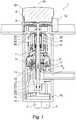
1 : ein Ventil in einem Längsschnitt.
1 : a valve in a longitudinal section.
Die
Das erste Bedienelement
Das Ventil
Durch die vorliegende Erfindung kann ein Ventil besonders kompakt ausgebildet werden.With the present invention, a valve can be made particularly compact.
BezugszeichenlisteList of reference symbols
- 11
- VentilValve
- 22
- VentilgehäuseValve body
- 33
- KaltwassereinlassCold water inlet
- 44th
- WarmwassereinlassHot water inlet
- 55
- MischwasserauslassMixed water outlet
- 66th
- MembranventilDiaphragm valve
- 77th
- HohlachseHollow axle
- 88th
- erstes Bedienelementfirst control element
- 99
- SchließstellungClosed position
- 1010
- MischventilMixing valve
- 1111
- SteuerachseControl axis
- 1212th
- zweites Bedienelementsecond control element
- 1313th
- ÖffnungshubOpening stroke
- 1414th
- erste Ventilscheibefirst valve disc
- 1515th
- zweite Ventilscheibesecond valve disc
- 1616
- Membranmembrane
- 1717th
- FührungsteilLeadership part
- 1818th
- VentilsitzValve seat
- 1919th
- SteueröffnungTax opening
- 2020th
- MischraumMixing room
- 2121
- StrömungskanalFlow channel
- 2222nd
- Ablaufsequence
- 2323
- DrehachseAxis of rotation
- 2424
- erster Abschnittfirst section
- 2525th
- zweiter Abschnittsecond part
- 2626th
- RasteinrichtungLocking device
- 2727
- DruckelementPrinting element
- 2828
- GewindehülseThreaded sleeve
- 2929
- Innengewindeinner thread
- 3030th
- AußengewindeExternal thread
- 3131
- VerbindungshülseConnecting sleeve
ZITATE ENTHALTEN IN DER BESCHREIBUNGQUOTES INCLUDED IN THE DESCRIPTION
Diese Liste der vom Anmelder aufgeführten Dokumente wurde automatisiert erzeugt und ist ausschließlich zur besseren Information des Lesers aufgenommen. Die Liste ist nicht Bestandteil der deutschen Patent- bzw. Gebrauchsmusteranmeldung. Das DPMA übernimmt keinerlei Haftung für etwaige Fehler oder Auslassungen.This list of the documents listed by the applicant was generated automatically and is included solely for the better information of the reader. The list is not part of the German patent or utility model application. The DPMA assumes no liability for any errors or omissions.
Zitierte PatentliteraturPatent literature cited
- EP 1903267 A1 [0003]EP 1903267 A1 [0003]
Claims (10)
Translated fromGermanPriority Applications (1)
| Application Number | Priority Date | Filing Date | Title |
|---|---|---|---|
| DE102020114022.3ADE102020114022A1 (en) | 2020-05-26 | 2020-05-26 | Valve for a concealed installation body of a sanitary fitting |
Applications Claiming Priority (1)
| Application Number | Priority Date | Filing Date | Title |
|---|---|---|---|
| DE102020114022.3ADE102020114022A1 (en) | 2020-05-26 | 2020-05-26 | Valve for a concealed installation body of a sanitary fitting |
Publications (1)
| Publication Number | Publication Date |
|---|---|
| DE102020114022A1true DE102020114022A1 (en) | 2021-12-02 |
Family
ID=78509021
Family Applications (1)
| Application Number | Title | Priority Date | Filing Date |
|---|---|---|---|
| DE102020114022.3APendingDE102020114022A1 (en) | 2020-05-26 | 2020-05-26 | Valve for a concealed installation body of a sanitary fitting |
Country Status (1)
| Country | Link |
|---|---|
| DE (1) | DE102020114022A1 (en) |
Cited By (2)
| Publication number | Priority date | Publication date | Assignee | Title |
|---|---|---|---|---|
| DE102023108275A1 (en) | 2023-03-31 | 2024-10-02 | Herbert Saier Gmbh | dosing device |
| DE102024109041A1 (en)* | 2024-03-28 | 2025-10-02 | Grohe Ag | Push-button valve for a sanitary fitting |
Citations (4)
| Publication number | Priority date | Publication date | Assignee | Title |
|---|---|---|---|---|
| DE2636517B2 (en) | 1976-08-13 | 1978-12-14 | Lorenz Dipl.-Ing. 1000 Berlin Claussen | Single-lever mixer tap |
| WO1992001883A1 (en) | 1990-07-23 | 1992-02-06 | Lin Zhixie | Push-button mixer tap |
| EP1903267A1 (en) | 2005-07-12 | 2008-03-26 | Inax Corporation | Pilot type water discharging/stopping and flow regulating valve device |
| EP2998622A1 (en) | 2014-09-17 | 2016-03-23 | Franke Aquarotter GmbH | Valve cartridge for a sanitary fitting |
- 2020
- 2020-05-26DEDE102020114022.3Apatent/DE102020114022A1/enactivePending
Patent Citations (4)
| Publication number | Priority date | Publication date | Assignee | Title |
|---|---|---|---|---|
| DE2636517B2 (en) | 1976-08-13 | 1978-12-14 | Lorenz Dipl.-Ing. 1000 Berlin Claussen | Single-lever mixer tap |
| WO1992001883A1 (en) | 1990-07-23 | 1992-02-06 | Lin Zhixie | Push-button mixer tap |
| EP1903267A1 (en) | 2005-07-12 | 2008-03-26 | Inax Corporation | Pilot type water discharging/stopping and flow regulating valve device |
| EP2998622A1 (en) | 2014-09-17 | 2016-03-23 | Franke Aquarotter GmbH | Valve cartridge for a sanitary fitting |
Cited By (3)
| Publication number | Priority date | Publication date | Assignee | Title |
|---|---|---|---|---|
| DE102023108275A1 (en) | 2023-03-31 | 2024-10-02 | Herbert Saier Gmbh | dosing device |
| EP4437924A1 (en) | 2023-03-31 | 2024-10-02 | Herbert Saier GmbH | Dosing device |
| DE102024109041A1 (en)* | 2024-03-28 | 2025-10-02 | Grohe Ag | Push-button valve for a sanitary fitting |
Similar Documents
| Publication | Publication Date | Title |
|---|---|---|
| EP2226697B1 (en) | Flow rate regulator | |
| EP3568622B1 (en) | Valve for a flush-mounted body of a sanitary fitting, having a control knob rotatably fastened to a valve knob | |
| EP1853769B1 (en) | Shower device | |
| DE102019103609A1 (en) | Valve for a concealed installation body of a sanitary fitting | |
| WO2020104230A1 (en) | Sanitary fitting with mixing valve and valve | |
| DE102020114022A1 (en) | Valve for a concealed installation body of a sanitary fitting | |
| EP3924652B1 (en) | Valve for a flush-mounted body of a sanitary fitting with a quantity-regulating part and a temperature-regulating part | |
| EP3613908B1 (en) | Method for installing a flush mounting body | |
| EP3599399B1 (en) | Plumbing valve with membrane valve | |
| EP4043651B1 (en) | Sanitary fitting with an actuating element | |
| EP3859483B1 (en) | Mixed water fitting with compact thermostatic valve | |
| DE102015002569A1 (en) | plumbing fixture | |
| EP3868964B1 (en) | Sanitary fitting with a non-axial thermostatic mixer | |
| DE102014113675A1 (en) | Time-delayed automatic closing faucet | |
| DE102006059577B4 (en) | Valve | |
| EP2570711B1 (en) | Coupling half for hose and pipes | |
| EP0452699A1 (en) | Sanitary mixing valve | |
| DE102015001025A1 (en) | plumbing fixture | |
| EP3467358A1 (en) | Directional control valve | |
| DE29804427U1 (en) | Flow control valve | |
| EP3715539B1 (en) | Multiway valve with a plurality of coupled membrane valves | |
| EP3375527B1 (en) | Shower head having an actuator and at least one sealing element, each having a shore hardness d | |
| DE102023124265A1 (en) | Shower with volume control device | |
| DE102021125490A1 (en) | Sanitary fitting with an actuating element | |
| DE102004022029A1 (en) | Sanitary equipment e.g. shower, valve, has outlet openings arranged in direction of movement of valve unit limited by stop surfaces, where one surface is so placed that one opening is completely opened in stop position |
Legal Events
| Date | Code | Title | Description |
|---|---|---|---|
| R163 | Identified publications notified |