DE102020111623A1 - DIGITAL BARCODE READER - Google Patents
DIGITAL BARCODE READERDownload PDFInfo
- Publication number
- DE102020111623A1 DE102020111623A1DE102020111623.3ADE102020111623ADE102020111623A1DE 102020111623 A1DE102020111623 A1DE 102020111623A1DE 102020111623 ADE102020111623 ADE 102020111623ADE 102020111623 A1DE102020111623 A1DE 102020111623A1
- Authority
- DE
- Germany
- Prior art keywords
- reader
- base
- frame
- platform
- assembly
- Prior art date
- Legal status (The legal status is an assumption and is not a legal conclusion. Google has not performed a legal analysis and makes no representation as to the accuracy of the status listed.)
- Granted
Links
Images


Classifications
- G—PHYSICS
- G06—COMPUTING OR CALCULATING; COUNTING
- G06K—GRAPHICAL DATA READING; PRESENTATION OF DATA; RECORD CARRIERS; HANDLING RECORD CARRIERS
- G06K7/00—Methods or arrangements for sensing record carriers, e.g. for reading patterns
- G06K7/10—Methods or arrangements for sensing record carriers, e.g. for reading patterns by electromagnetic radiation, e.g. optical sensing; by corpuscular radiation
- G06K7/10544—Methods or arrangements for sensing record carriers, e.g. for reading patterns by electromagnetic radiation, e.g. optical sensing; by corpuscular radiation by scanning of the records by radiation in the optical part of the electromagnetic spectrum
- G06K7/10821—Methods or arrangements for sensing record carriers, e.g. for reading patterns by electromagnetic radiation, e.g. optical sensing; by corpuscular radiation by scanning of the records by radiation in the optical part of the electromagnetic spectrum further details of bar or optical code scanning devices
- G06K7/10881—Methods or arrangements for sensing record carriers, e.g. for reading patterns by electromagnetic radiation, e.g. optical sensing; by corpuscular radiation by scanning of the records by radiation in the optical part of the electromagnetic spectrum further details of bar or optical code scanning devices constructional details of hand-held scanners
- G06K7/109—Methods or arrangements for sensing record carriers, e.g. for reading patterns by electromagnetic radiation, e.g. optical sensing; by corpuscular radiation by scanning of the records by radiation in the optical part of the electromagnetic spectrum further details of bar or optical code scanning devices constructional details of hand-held scanners adaptations to make the hand-held scanner useable as a fixed scanner
- G—PHYSICS
- G06—COMPUTING OR CALCULATING; COUNTING
- G06K—GRAPHICAL DATA READING; PRESENTATION OF DATA; RECORD CARRIERS; HANDLING RECORD CARRIERS
- G06K7/00—Methods or arrangements for sensing record carriers, e.g. for reading patterns
- G06K7/10—Methods or arrangements for sensing record carriers, e.g. for reading patterns by electromagnetic radiation, e.g. optical sensing; by corpuscular radiation
- G06K7/10009—Methods or arrangements for sensing record carriers, e.g. for reading patterns by electromagnetic radiation, e.g. optical sensing; by corpuscular radiation sensing by radiation using wavelengths larger than 0.1 mm, e.g. radio-waves or microwaves
- G06K7/10366—Methods or arrangements for sensing record carriers, e.g. for reading patterns by electromagnetic radiation, e.g. optical sensing; by corpuscular radiation sensing by radiation using wavelengths larger than 0.1 mm, e.g. radio-waves or microwaves the interrogation device being adapted for miscellaneous applications
- G06K7/10415—Methods or arrangements for sensing record carriers, e.g. for reading patterns by electromagnetic radiation, e.g. optical sensing; by corpuscular radiation sensing by radiation using wavelengths larger than 0.1 mm, e.g. radio-waves or microwaves the interrogation device being adapted for miscellaneous applications the interrogation device being fixed in its position, such as an access control device for reading wireless access cards, or a wireless ATM
- G—PHYSICS
- G06—COMPUTING OR CALCULATING; COUNTING
- G06K—GRAPHICAL DATA READING; PRESENTATION OF DATA; RECORD CARRIERS; HANDLING RECORD CARRIERS
- G06K7/00—Methods or arrangements for sensing record carriers, e.g. for reading patterns
- G06K7/10—Methods or arrangements for sensing record carriers, e.g. for reading patterns by electromagnetic radiation, e.g. optical sensing; by corpuscular radiation
- G06K7/10544—Methods or arrangements for sensing record carriers, e.g. for reading patterns by electromagnetic radiation, e.g. optical sensing; by corpuscular radiation by scanning of the records by radiation in the optical part of the electromagnetic spectrum
- G06K7/10712—Fixed beam scanning
- G06K7/10722—Photodetector array or CCD scanning
- H—ELECTRICITY
- H05—ELECTRIC TECHNIQUES NOT OTHERWISE PROVIDED FOR
- H05K—PRINTED CIRCUITS; CASINGS OR CONSTRUCTIONAL DETAILS OF ELECTRIC APPARATUS; MANUFACTURE OF ASSEMBLAGES OF ELECTRICAL COMPONENTS
- H05K5/00—Casings, cabinets or drawers for electric apparatus
- H05K5/02—Details
- H05K5/0217—Mechanical details of casings
Landscapes
- Physics & Mathematics (AREA)
- Engineering & Computer Science (AREA)
- Electromagnetism (AREA)
- Health & Medical Sciences (AREA)
- Toxicology (AREA)
- Artificial Intelligence (AREA)
- General Health & Medical Sciences (AREA)
- Computer Vision & Pattern Recognition (AREA)
- General Physics & Mathematics (AREA)
- Theoretical Computer Science (AREA)
- Microelectronics & Electronic Packaging (AREA)
- Computer Networks & Wireless Communication (AREA)
- Casings For Electric Apparatus (AREA)
- Automatic Analysis And Handling Materials Therefor (AREA)
- Cash Registers Or Receiving Machines (AREA)
Abstract
Translated fromGermanDescription
Translated fromGermanHINTERGRUND DER ERFINDUNGBACKGROUND OF THE INVENTION
Strichcode- und andere Scangeräte erfassen im Allgemeinen Bilder innerhalb eines gegebenen Sichtfeldes (FOV). In einigen Fällen werden Strichcode-Lesegeräte bekanntermaßen in Multimodus-Umgebungen eingesetzt, in denen dasselbe Lesegerät zusätzlich zu einem Präsentationsmodus, in dem ein Produkt dem Lesegerät präsentiert wird und das Lesegerät eine Bildgebungsbaugruppe aktiviert, auch in einem handgehaltenen Modus verwendet werden kann. Daher gibt es verschiedene Situationen, in denen das Lesegerät in der Hand gehalten und bewegt werden muss, oder es kann bevorzugt sein, das Lesegerät auf einer stabilen Oberfläche wie einem Tisch oder einer Arbeitsfläche zu platzieren.Barcode and other scanning devices generally capture images within a given field of view (FOV). In some instances, bar code readers are known to be used in multi-mode environments where the same reader can be used in a handheld mode in addition to a presentation mode in which a product is presented to the reader and the reader activates an imaging assembly. As such, there are various situations in which the reader must be hand-held and moved, or it may be preferable to place the reader on a stable surface such as a table or work surface.
Dementsprechend besteht ein Bedarf an verbessertem Zubehör mit verbesserten Funktionalitäten.Accordingly, there is a need for improved accessories with improved functionality.
FigurenlisteFigure list
Die beigefügten Figuren, in denen gleiche Bezugszeichen identische oder funktional ähnliche Elemente in den einzelnen Ansichten bezeichnen, sind zusammen mit der nachfolgenden detaillierten Beschreibung in die Offenbarung inkorporiert und bilden einen Bestandteil der Offenbarung und dienen dazu, hierin beschriebene Ausführungsformen von Konzepten, die die beanspruchte Erfindung umfassen, weiter zu veranschaulichen und verschiedene Prinzipien und Vorteile dieser Ausführungsformen zu erklären.
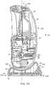
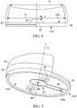
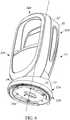
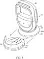
1 ist eine Vorderansicht einer tragbaren, industriellen digitalen Strichcode-Lesegerät-Baugruppe mit einem Lesegerät und einem Gestell gemäß dieser Offenbarung.2A ist eine Seitenansicht der industriellen digitalen Strichcode-Lesegerät-Baugruppe von1 gemäß dieser Offenbarung.2B ist eine seitliche Querschnittsansicht des industriellen digitalen Strichcode-Lesegeräts der1 und2A gemäß dieser Offenbarung.3 ist eine perspektivische Rückansicht des Gestells der1-2B in isolierter Form gemäß dieser Offenbarung.4 ist eine Rückansicht des Gestells der1-3 in isolierter Form gemäß dieser Offenbarung.5 ist eine perspektivische Unteransicht des Gestells der1-4 in isolierter Form gemäß dieser Offenbarung.6 ist eine perspektivische Unteransicht des Lesegerätes der1-2B gemäß dieser Offenbarung.7 ist eine perspektivische Ansicht der digitalen Strichcode-Lesegerät-Baugruppe der1-6 , die die Kopplung des Lesegeräts an das Gestell gemäß dieser Offenbarung veranschaulicht.
1 Figure 4 is a front view of a portable, industrial digital barcode reader assembly having a reader and a stand in accordance with this disclosure.2A FIG. 13 is a side view of the industrial digital barcode reader assembly of FIG1 according to this disclosure.2 B FIG. 13 is a side cross-sectional view of the industrial digital bar code reader of FIG1 and2A according to this disclosure.3 FIG. 13 is a rear perspective view of the frame of FIG1-2B in isolated form according to this disclosure.4th FIG. 13 is a rear view of the frame of FIG1-3 in isolated form according to this disclosure.5 FIG. 14 is a bottom perspective view of the frame of FIG1-4 in isolated form according to this disclosure.6th FIG. 13 is a bottom perspective view of the reader of FIG1-2B according to this disclosure.7th FIG. 13 is a perspective view of the digital bar code reader assembly of FIG1-6 illustrating the coupling of the reader to the rack in accordance with this disclosure.
Fachleute werden erkennen, dass Elemente in den Figuren der Einfachheit und Klarheit halber dargestellt sind und nicht notwendigerweise maßstabsgetreu gezeichnet wurden. Zum Beispiel können die Dimensionen einiger der Elemente in den Figuren relativ zu anderen Elementen übertrieben sein, um das Verständnis von Ausführungsformen der vorliegenden Erfindung zu verbessern.Those skilled in the art will recognize that elements in the figures are shown for simplicity and clarity, and are not necessarily drawn to scale. For example, the dimensions of some of the elements in the figures may be exaggerated relative to other elements in order to improve understanding of embodiments of the present invention.
Die Vorrichtungs- und Verfahrenskomponenten wurden, wo es angemessen ist, durch herkömmliche Symbole in den Zeichnungen dargestellt, die nur jene spezifischen Details zeigen, die zum Verständnis der Ausführungsformen der vorliegenden Erfindung relevant sind, um somit die Offenbarung nicht mit Einzelheiten zu verdecken, die für die Fachleute auf dem Gebiet, die auf die vorliegende Beschreibung zurückgreifen, ohne weiteres ersichtlich sind.The apparatus and method components have, where appropriate, been represented by conventional symbols in the drawings showing only those specific details relevant to an understanding of embodiments of the present invention, so as not to obscure the disclosure with details necessary to those skilled in the art having recourse to the present description will be readily apparent.
DETAILLIERTE BESCHREIBUNGDETAILED DESCRIPTION
In einer Ausführungsform stellt die vorliegende Anwendung eine Strichcode-Lesegerät-Baugruppe zum Erfassen mindestens eines in einem Sichtfeld (FOV) erscheinenden Objekts bereit, die ein Lesegerät und ein Gestell umfasst. Das Lesegerät umfasst ein Lesegerätgehäuse mit einem oberen Abschnitt und einem unteren Abschnitt sowie eine Lesegerätbasis mit einer gekrümmten Basisfläche. Der untere Abschnitt des Lesegerätgehäuses ist mechanisch mit der Lesegerätbasis gekoppelt. Das Gestell umfasst eine Plattform und eine Wand, die sich von dieser im Allgemeinen nach oben erstreckt. Die Lesegerätbasis ist mechanisch mit dem Gestell gekoppelt, so dass das Lesegerät relativ zum Gestell drehbar ist.In one embodiment, the present application provides a bar code reader assembly for sensing at least one object appearing in a field of view (FOV) that includes a reader and a frame. The reader includes a reader housing having an upper portion and a lower portion and a reader base having a curved base surface. The lower portion of the reader housing is mechanically coupled to the reader base. The frame includes a platform and a wall extending generally upwardly therefrom. The reader base is mechanically coupled to the frame so that the reader is rotatable relative to the frame.
In einigen Aspekten ist die Lesegerätbasis über eine mechanische Verbindung an die Plattform gekoppelt. Die mechanische Verbindung kann eine elastische Fingerkomponente mit einem daraus herausragenden Vorsprung umfassen. Der elastische Finger kann von mindestens einem der Lesegerätbasis oder der Plattform getragen werden. Dieser Vorsprung kann die Form einer abgewinkelten Seitenwand haben, die drehbar in eine Verbindungsöffnung eingreift. In einigen Beispielen enthält mindestens eine der abgewinkelten Seitenwand oder der Verbindungsöffnung mindestens eine Arretierung, um eine relative Drehung des Lesegerätes im Gestell selektiv zu begrenzen. In einigen dieser Beispiele arbeitet die mechanische Verbindung mit der Wand des Gestells zusammen, um eine relative Translationsbewegung zwischen dem Lesegerät und dem Gestell zu begrenzen.In some aspects, the reader base is mechanically coupled to the platform. The mechanical connection can comprise an elastic finger component with a protrusion protruding therefrom. The resilient finger can be carried on at least one of the reader base or the platform. This projection can be in the form of an angled side wall which rotatably engages in a connecting opening. In some examples, at least one of the angled sidewall or connection port includes at least one detent to selectively limit relative rotation of the reader in the rack. In some of these examples the mechanical connection works with the wall of the frame together to limit relative translational movement between the reader and the rack.
In einigen Formen kann die Plattform zusätzlich einen Befestigungsmechanismus zur Befestigung des Gestells an einer Anzeigefläche enthalten. Dieser Befestigungsmechanismus kann die Form einer Durchgangsbohrung haben. Die mechanische Verbindung kann auch ein Entkopplungselement enthalten, um das Lesegerät vom Gestell zu entkoppeln. Dieses Entkopplungselement kann auf der elastischen Fingerkomponente ausgebildet sein.In some forms, the platform can additionally include an attachment mechanism for attaching the frame to a display surface. This fastening mechanism can be in the form of a through hole. The mechanical connection can also contain a decoupling element in order to decouple the reader from the frame. This decoupling element can be formed on the elastic finger component.
Bei einigen Ansätzen kann die Wand eine Öffnung enthalten, die so bemessen ist, dass sie ein an das Lesegerät gekoppeltes Anschlusskabel aufnehmen kann. In einigen Beispielen enthält die Wand eine Öffnung zur Aufnahme eines Abschnitts der Lesegerätbasis.In some approaches, the wall may include an opening that is sized to receive a connector cable coupled to the reader. In some examples, the wall includes an opening for receiving a portion of the reader base.
In einer anderen Implementierung umfasst eine Zubehörbasis für ein Strichcode-Lesegerät zum Erfassuen mindestens eines Bildes eines in einem Sichtfeld (FOV) erscheinenden Objekts eine Plattform mit einem Umfang, eine sich von der Plattform aus im Allgemeinen um deren Umfang nach oben erstreckende Wand und eine von der Plattform gebildete mechanische Verbindung. Die mechanische Verbindung umfasst eine elastische Fingerkomponente mit einem sich davon erstreckenden Vorsprung.In another implementation, a barcode reader accessory base for capturing at least one image of an object appearing in a field of view (FOV) includes a platform having a perimeter, a wall extending upwardly from the platform generally around the perimeter thereof, and one from mechanical connection formed by the platform. The mechanical connection includes a resilient finger component with a protrusion extending therefrom.
In einer weiteren Implementierung umfasst eine Strichcode-Lesegerät-Baugruppe zum Erfassen mindestens eines Bildes eines in einem Sichtfeld (FOV) erscheinenden Objekts ein Lesegerät und ein Gestell. Das Lesegerät umfasst ein Lesegerätgehäuse mit einem oberen und einem unteren Abschnitt. Die Lesegerätbasis umfasst eine gekrümmte Basisfläche. Der untere Abschnitt des Lesegerätgehäuses ist mechanisch mit der Lesegerätbasis verbunden. Das Gestell umfasst eine Plattform und eine gekrümmte Wand, die sich von dieser im Allgemeinen nach oben erstreckt, und ist mechanisch mit der Lesegerätbasis gekoppelt, so dass das Lesegerät relativ zum Gestell drehbar ist. Wenn das Lesegerät mechanisch mit dem Gestell gekoppelt ist, sind die gekrümmte Basisfläche der Lesegerätbasis und die gekrümmte Wand des Gestells so ineinander verschachtelt, dass zwischen der gekrümmten Basisfläche und der gekrümmten Lesegerätgehäuseoberfläche ein Abstand von weniger als etwa 5 mm gebildet wird.In another implementation, a bar code reader assembly for capturing at least one image of an object appearing in a field of view (FOV) includes a reader and a frame. The reader includes a reader housing having upper and lower sections. The reader base includes a curved base surface. The lower portion of the reader housing is mechanically connected to the reader base. The rack includes a platform and a curved wall extending generally upwardly therefrom and is mechanically coupled to the reader base so that the reader is rotatable relative to the rack. When the reader is mechanically coupled to the cradle, the curved base of the reader base and the curved wall of the cradle are nested so that a clearance of less than about 5 mm is formed between the curved base and the curved reader housing surface.
Mit Bezug zu den Figuren identifiziert die Referenznummer
Die Basis
Das Lesegerätgehäuse
Im abgebildeten Beispiel ist der untere Abschnitt
Das elastische Element
In dem abgebildeten Beispiel umfasst das Gestell
Die Wand
In einer bevorzugten Ausführung hat ein von oben nach unten verlaufender Querschnitt der Basis
Das Gestell
Die Plattform
Am distalen Ende
Im Allgemeinen ist der elastische Finger
Da die Wand
Das elastische Element
Zur Bedienung und/oder Neupositionierung des Lesegeräts
In jeder dieser Konfigurationen der abgewinkelten Seitenwand
In anderen Beispielen kann der Auslösemechanismus
In einigen Aspekten kann die Strichcode-Lesegerät-Baugruppe
In einigen Aspekten kann die Verbindungsöffnung
Bei einigen Ansätzen kann das Lesegerät
In einigen Beispielen kann die Anordnung der Komponenten der Strichcode-Lesegerät-Baugruppe
Bei dieser Konfiguration kann die Strichcode-Lesegerät-Baugruppe
In einer oder allen dieser Implementierungen kann die Strichcode-Lesegerät-Baugruppe
In der vorstehenden Beschreibung wurden spezifische Ausführungsformen beschrieben. Ein Durchschnittsfachmann erkennt jedoch, dass verschiedene Modifikationen und Änderungen vorgenommen werden können, ohne den Schutzumfang der Erfindung, wie sie in den untenstehenden Ansprüchen definiert ist, abzuweichen. Dementsprechend sind die Beschreibung und die Figuren vielmehr in einem illustrativen als in einem einschränkenden Sinne zu betrachten, und alle derartigen Modifikationen sollen im Umfang der vorliegenden Lehren eingeschlossen sein. Darüber hinaus sollten die beschriebenen Ausführungsformen/Beispiele/Implementierungen nicht als sich gegenseitig ausschließend interpretiert werden und stattdessen als potentiell kombinierbar verstanden werden, wenn solche Kombinationen in irgendeiner Weise permissiv sind. Mit anderen Worten, jedes Merkmal, das in einer der oben genannten Ausführungsformen/Beispiele/Implementierungen offenbart wird, kann in jeder der anderen oben genannten Ausführungsformen/Beispiele/Implementierungen enthalten sein.In the above description, specific embodiments have been described. However, one of ordinary skill in the art will recognize various modifications and changes can be made without departing from the scope of the invention as defined in the claims below. Accordingly, the specification and figures are to be regarded in an illustrative rather than a restrictive sense, and all such modifications are intended to be included within the scope of the present teachings. In addition, the described embodiments / examples / implementations should not be interpreted as mutually exclusive and should instead be understood as potentially combinable if such combinations are permissive in any way. In other words, any feature disclosed in any of the above embodiments / examples / implementations may be included in any of the other above embodiments / examples / implementations.
Die Nutzen, Vorteile, Lösungen für Probleme und alle Elemente, die zum Auftreten oder einer Verstärkung eines Nutzens, eines Vorteils, oder einer Lösung führen können, sind nicht als kritische, erforderliche oder wesentliche Merkmale oder Elemente in einigen oder sämtlichen Ansprüchen zu verstehen. Die Erfindung ist lediglich durch die angehängten Ansprüche definiert, einschließlich jeglicher Änderungen, die während der Anhängigkeit dieser Anmeldung vorgenommen wurden und aller Äquivalente der erteilten Ansprüche.The benefits, advantages, solutions to problems and all elements that may lead to the occurrence or amplification of a benefit, an advantage or a solution are not to be understood as critical, required or essential features or elements in any or all of the claims. The invention is defined only by the appended claims, including any changes made during the pendency of this application and all equivalents of the granted claims.
Darüber hinaus können in diesem Dokument relationale Begriffe wie erster und zweiter, oberer und unterer und dergleichen lediglich verwendet sein, um eine Entität oder Aktion von einer anderen Entität oder Aktion zu unterscheiden, ohne notwendigerweise eine tatsächliche derartige Beziehung oder Reihenfolge zwischen solchen Entitäten oder Aktionen zu erfordern oder zu implizieren. Die Ausdrücke „umfasst“, „umfassend“, „hat“, „haben“, „aufweist“, „aufweisend“, „enthält“, „enthaltend“ oder jede andere Variation davon sollen eine nicht-ausschließliche Einbeziehung abdecken, derart, dass ein Prozess, Verfahren, Produkt oder Vorrichtung, das eine Liste von Elementen umfasst, hat, aufweist, enthält, nicht nur diese Elemente aufweist, sondern auch andere Elemente aufweisen kann, die nicht ausdrücklich aufgelistet sind oder einem solchen Prozess, Verfahren, Produkt oder Vorrichtung inhärent sind. Ein Element, dem „umfasst ... ein“, „hat ... ein“, „aufweist ... ein“ oder „enthält ...ein“ vorausgeht, schließt ohne weitere Einschränkungen die Existenz zusätzlicher identischer Elemente in dem Prozess, dem Verfahren, dem Produkt oder der Vorrichtung, die das Element umfasst, hat, aufweist oder enthält, nicht aus. Die Begriffe „ein“ und „eine“ sind als eine oder mehrere definiert, sofern es hierin nicht ausdrücklich anders angegeben wird. Die Begriffe „im Wesentlichen“, „im Allgemeinen“, „ungefähr“, „etwa“ oder jede andere Version davon sind so definiert, dass sie von einem Fachmann auf diesem Gebiet nahekommend verstanden werden, und in einer nicht-einschränkenden Ausführungsform ist der Ausdruck definiert als innerhalb von 10%, in einer weiteren Ausführungsform als innerhalb von 5%, in einer weiteren Ausführungsform als innerhalb von 1 % und in einer weiteren Ausführungsform als innerhalb von 0,5%. Der Ausdruck „gekoppelt“, wie er hierin verwendet wird, ist als verbunden definiert, jedoch nicht notwendigerweise direkt und nicht notwendigerweise mechanisch. Eine Vorrichtung oder eine Struktur, die auf eine bestimmte Art „ausgeführt“ ist, ist zumindest auch so ausgeführt, kann aber auch auf Arten ausgeführt sein, die nicht aufgeführt sind.Furthermore, relational terms such as first and second, upper and lower, and the like, may be used in this document merely to distinguish one entity or action from another entity or action, without necessarily implying any actual such relationship or order between such entities or actions require or imply. The terms “comprises”, “comprising”, “has”, “having”, “has”, “having”, “contains”, “containing” or any other variation thereof are intended to cover non-exclusive inclusion such that a Process, method, product or device that comprises, has, has, contains, not only has these elements, but may also have other elements that are not expressly listed or are inherent in such a process, method, product or device are. An element preceded by "comprises ... a", "has ... a", "has ... a" or "contains ... a" excludes, without further restrictions, the existence of additional identical elements in the process, does not affect the method, product or device comprising, having, or containing the element. The terms “a” and “an” are defined as one or more unless expressly stated otherwise herein. The terms “substantially,” “generally,” “approximately,” “about,” or any other version thereof, are defined to be readily understood by one of ordinary skill in the art, and in one non-limiting embodiment, the term is defined as within 10%, in a further embodiment as within 5%, in a further embodiment as within 1% and in a further embodiment as within 0.5%. As used herein, the term “coupled” is defined as connected, but not necessarily directly and not necessarily mechanically. A device or a structure that is “designed” in a certain way is at least also designed that way, but can also be designed in ways that are not listed.
Es versteht sich, dass einige Ausführungsformen von einem oder mehreren generischen oder spezialisierten Prozessoren (oder „Verarbeitungsgeräten“) wie Mikroprozessoren, digitale Signalprozessoren, kundenspezifische Prozessoren und Field-Programmable-Gate-Arrays (FPGAs) und einmalig gespeicherten Programmanweisungen (einschließlich sowohl Software als auch Firmware) umfasst sein können, die den einen oder die mehreren Prozessoren steuern, um in Verbindung mit bestimmten Nicht-Prozessorschaltungen einige, die meisten oder alle der hierin beschriebenen Funktionen des Verfahrens und/oder der Vorrichtung zu implementieren. Alternativ können einige oder alle Funktionen durch eine Zustandsmaschine implementiert sein, die keine gespeicherten Programmanweisungen aufweist, oder in einer oder mehreren anwendungsspezifischen integrierten Schaltungen (ASICs), in denen jede Funktion oder einige Kombinationen von bestimmten Funktionen als benutzerdefinierte Logik implementiert sind. Natürlich kann eine Kombination der beiden Ansätze verwendet werden.It is understood that some embodiments may include one or more generic or specialized processors (or "processing devices") such as microprocessors, digital signal processors, custom processors, and field programmable gate arrays (FPGAs) and one-time stored program instructions (including both software and Firmware) that control the one or more processors to implement some, most, or all of the functions of the method and / or apparatus described herein in conjunction with certain non-processor circuitry. Alternatively, some or all of the functions may be implemented by a state machine that does not have stored program instructions or in one or more application specific integrated circuits (ASICs) in which each function or some combination of certain functions are implemented as user-defined logic. Of course, a combination of the two approaches can be used.
Darüber hinaus kann eine Ausführungsform als ein computerlesbares Speichermedium implementiert sein, auf dem computerlesbarer Code gespeichert ist, um einen Computer (der zum Beispiel einen Prozessor umfasst) zu programmieren, um ein Verfahren auszuführen, wie es hierin beschrieben und beansprucht ist. Beispiele solcher computerlesbaren Speichermedien weisen eine Festplatte, eine CD-ROM, eine optische Speichervorrichtung, eine magnetische Speichervorrichtung, einen ROM (Nur-Lese-Speicher), einen PROM (programmierbarer Nur-Lese-Speicher), einen EPROM (löschbarer programmierbarer Nur-Lese-Speicher), einen EEPROM (elektrisch löschbarer programmierbarer Nur-Lese-Speicher) und einen Flash-Speicher auf, sind aber nicht hierauf beschränkt auf. Ferner wird davon ausgegangen, dass ein Durchschnittsfachmann, ungeachtet möglicher signifikanter Anstrengungen und vieler Designwahlen, die zum Beispiel durch verfügbare Zeit, aktuelle Technologie und wirtschaftliche Überlegungen motiviert sind, ohne Weiteres in der Lage ist, solche Softwareanweisungen und - programme und ICs mit minimalem Experimentieren zu generieren, wenn er durch die hierin offenbarten Konzepte und Prinzipien angeleitet wird.Additionally, an embodiment may be implemented as a computer readable storage medium having stored thereon computer readable code for programming a computer (e.g., comprising a processor) to perform a method as described and claimed herein. Examples of such computer readable storage media include a hard disk, a CD-ROM, an optical storage device, a magnetic storage device, a ROM (read only memory), a PROM (programmable read only memory), an EPROM (erasable programmable read only memory) Memory), an EEPROM (electrically erasable programmable read-only memory) and a flash memory to, but are not limited to. Further, it is believed that one of ordinary skill in the art, regardless of potentially significant efforts and many design choices, motivated by, for example, available time, current technology, and economic considerations, would be readily able to use such software instructions and - generate programs and ICs with minimal experimentation when guided by the concepts and principles disclosed herein.
Die Zusammenfassung der Offenbarung wird bereitgestellt, um es dem Leser zu ermöglichen, schnell das Wesen der technischen Offenbarung zu ermitteln. Sie wird mit dem Verständnis bereitgestellt, dass sie nicht zur Auslegung oder Einschränkung des Umfangs oder der Bedeutung der Ansprüche verwendet wird. Ferner kann der vorangehenden detaillierten Beschreibung entnommen werden, dass verschiedene Merkmale in verschiedenen Ausführungsformen zum Zwecke der Verschlankung der Offenbarung zusammengefasst sind. Diese Art der Offenbarung ist nicht so auszulegen, dass sie die Absicht widerspiegelt, dass die beanspruchten Ausführungsformen mehr Merkmale erfordern, als ausdrücklich in jedem Anspruch angegeben sind. Vielmehr ist es so, wie die folgenden Ansprüche zeigen, dass der erfinderische Gegenstand in weniger als allen Merkmalen einer einzigen offenbarten Ausführungsform liegt. Somit werden die folgenden Ansprüche hiermit in die detaillierte Beschreibung inkorporiert, wobei jeder Anspruch für sich als ein separat beanspruchter Gegenstand steht.The abstract of the disclosure is provided to enable the reader to quickly ascertain the nature of the technical disclosure. It is provided with the understanding that it will not be used to interpret or limit the scope or meaning of the claims. Furthermore, it can be inferred from the preceding detailed description that various features are combined in various embodiments for the purpose of streamlining the disclosure. This kind of disclosure is not to be construed as reflecting the intent that the claimed embodiments require more features than are expressly stated in each claim. Rather, as the following claims demonstrate, inventive subject matter resides in less than all features of a single disclosed embodiment. Thus, the following claims are hereby incorporated into the Detailed Description, with each claim standing on its own as a separately claimed subject matter.
ZITATE ENTHALTEN IN DER BESCHREIBUNGQUOTES INCLUDED IN THE DESCRIPTION
Diese Liste der vom Anmelder aufgeführten Dokumente wurde automatisiert erzeugt und ist ausschließlich zur besseren Information des Lesers aufgenommen. Die Liste ist nicht Bestandteil der deutschen Patent- bzw. Gebrauchsmusteranmeldung. Das DPMA übernimmt keinerlei Haftung für etwaige Fehler oder Auslassungen.This list of the documents listed by the applicant was generated automatically and is included solely for the better information of the reader. The list is not part of the German patent or utility model application. The DPMA assumes no liability for any errors or omissions.
Zitierte PatentliteraturPatent literature cited
- US 16245969 [0015]US 16245969 [0015]
Claims (25)
Translated fromGermanApplications Claiming Priority (2)
| Application Number | Priority Date | Filing Date | Title |
|---|---|---|---|
| US16/430,167US12141651B2 (en) | 2019-06-03 | 2019-06-03 | Digital barcode reader |
| US16/430,167 | 2019-06-03 |
Publications (1)
| Publication Number | Publication Date |
|---|---|
| DE102020111623A1true DE102020111623A1 (en) | 2020-12-03 |
Family
ID=72422008
Family Applications (1)
| Application Number | Title | Priority Date | Filing Date |
|---|---|---|---|
| DE102020111623.3AGrantedDE102020111623A1 (en) | 2019-06-03 | 2020-04-29 | DIGITAL BARCODE READER |
Country Status (5)
| Country | Link |
|---|---|
| US (1) | US12141651B2 (en) |
| CN (1) | CN112036198B (en) |
| AU (1) | AU2020201931B2 (en) |
| BE (1) | BE1027293B1 (en) |
| DE (1) | DE102020111623A1 (en) |
Families Citing this family (3)
| Publication number | Priority date | Publication date | Assignee | Title |
|---|---|---|---|---|
| USD910021S1 (en)* | 2019-01-11 | 2021-02-09 | Zebra Technologies Corporation | Data capture device |
| US12141651B2 (en)* | 2019-06-03 | 2024-11-12 | Zebra Technologies Corporation | Digital barcode reader |
| US11583058B2 (en) | 2021-01-27 | 2023-02-21 | Hand Held Products, Inc. | Attachment device |
Family Cites Families (84)
| Publication number | Priority date | Publication date | Assignee | Title |
|---|---|---|---|---|
| US4589713A (en)* | 1984-04-09 | 1986-05-20 | Raytheon Company | Video display support joint |
| US4645153A (en)* | 1985-05-23 | 1987-02-24 | Ncr Corporation | Tilt and swivel support |
| KR910008387B1 (en)* | 1987-09-22 | 1991-10-15 | 도오또오 덴끼 가부시끼가이샤 | Apparatus for reading commodity data |
| US5539193A (en)* | 1989-06-07 | 1996-07-23 | Norand Corporation | Modular hand-held data entry system |
| US6053413A (en)* | 1989-06-16 | 2000-04-25 | Symbol Technologies, Inc. | Optical scanner with hand-held and hands-free modes of use |
| US6575370B1 (en)* | 1990-05-08 | 2003-06-10 | Symbol Technologies, Inc. | Electro-optical scanning assembly with one-piece, oscillatable, focusing/scan element |
| US5861615A (en)* | 1990-05-08 | 1999-01-19 | Symbol Technologies, Inc. | Palm scanner |
| US6257492B1 (en)* | 1990-09-10 | 2001-07-10 | Peter Bressler | Combination hand-held and counter-top omni-directional scanner |
| US5340973A (en)* | 1990-09-17 | 1994-08-23 | Metrologic Instruments, Inc. | Automatic laser scanning system and method of reading bar code symbols using same |
| US6651890B2 (en)* | 1990-09-10 | 2003-11-25 | Sung Ho Byun | Combination hand-held and counter-top omnidirectional scanner |
| US20010017320A1 (en)* | 1990-09-10 | 2001-08-30 | Knowles Carl H. | Projection laser scanner for scanning bar codes within a confined scanning volume |
| US5216232A (en)* | 1990-09-10 | 1993-06-01 | Metrologic Instruments, Inc. | Projection laser scanner producing a narrow scan volume |
| US5108062A (en)* | 1990-09-28 | 1992-04-28 | Ncr Corporation | Pivot apparatus |
| US5198650A (en) | 1991-06-24 | 1993-03-30 | Ncr Corporation | Hands free/hand held bar code scanner |
| AU4282593A (en) | 1992-04-17 | 1993-11-18 | Spectra-Physics Scanning Systems, Inc. | Ultra-compact bar-code scanner |
| US6604684B1 (en)* | 1993-11-24 | 2003-08-12 | Metrologic Instruments Inc. | Automatic optical projection scanner for omni-directional reading of bar code symbols within a confined scanning volume |
| US5477044A (en)* | 1994-07-22 | 1995-12-19 | Intermec Corporation | Symbology reader with a variable orientation head |
| US5612530A (en)* | 1995-01-24 | 1997-03-18 | Symbol Technologies, Inc. | Scanner with pre-programmed working ranges |
| JPH0991368A (en)* | 1995-07-20 | 1997-04-04 | Fujitsu Ltd | Optical reader |
| US6811086B1 (en)* | 1995-07-20 | 2004-11-02 | Fujitsu Limited | Stand for pivotably mounting an optical reading device |
| US5750975A (en)* | 1995-08-25 | 1998-05-12 | Teletransactions, Inc. | Hand held bar code dataform reader having a rotatable reading assembly |
| US6575368B1 (en) | 1996-01-31 | 2003-06-10 | Psc Scanning, Inc. | Multiple aperture data reader for multi-mode operation |
| US6034379A (en)* | 1996-03-01 | 2000-03-07 | Intermec Ip Corp. | Code reader having replaceable optics assemblies supporting multiple illuminators |
| JP3438801B2 (en)* | 1996-03-27 | 2003-08-18 | 富士通株式会社 | Information reading device |
| KR100212314B1 (en)* | 1996-11-06 | 1999-08-02 | 윤종용 | Stand structure of liquid crystal display device |
| JP3738577B2 (en)* | 1998-02-13 | 2006-01-25 | 株式会社村田製作所 | ANTENNA DEVICE AND MOBILE COMMUNICATION DEVICE |
| US6561429B2 (en)* | 1998-07-21 | 2003-05-13 | Eastman Kodak Company | Adjustable reader arrangement and method of reading encoded indicia formed on an object |
| JP2000148899A (en)* | 1998-09-01 | 2000-05-30 | Tohoku Ricoh Co Ltd | Stand with communication function for bar-code reader |
| US6523751B2 (en)* | 2000-12-15 | 2003-02-25 | Yu-Chun Chang | Scanning apparatus |
| KR100395092B1 (en)* | 2001-07-27 | 2003-08-21 | 삼성전기주식회사 | A Wireless LAN Adapter |
| US7889489B2 (en)* | 2001-11-19 | 2011-02-15 | Otter Products, Llc | Detachable pod assembly for protective case |
| CA2453766A1 (en)* | 2003-01-02 | 2004-07-02 | Societe Des Loteries Video Du Quebec, Inc. | Bar code reader stand |
| JP4021335B2 (en)* | 2003-01-31 | 2007-12-12 | ユニバーサル・バイオ・リサーチ株式会社 | Dispensing device with monitoring function and method for monitoring dispensing device |
| WO2004084305A1 (en)* | 2003-03-19 | 2004-09-30 | Fujitsu Limited | Semiconductor device, process for producing the same and imaging device |
| US20080302873A1 (en)* | 2003-11-13 | 2008-12-11 | Metrologic Instruments, Inc. | Digital image capture and processing system supporting automatic communication interface testing/detection and system configuration parameter (SCP) programming |
| USD493802S1 (en)* | 2003-11-17 | 2004-08-03 | Symbol Technologies, Inc. | Bar code scanner stand |
| GB2412470B (en) | 2004-03-26 | 2006-07-26 | Motorola Inc | Mobile data processing handsets |
| US7504998B2 (en)* | 2004-12-08 | 2009-03-17 | Electronics And Telecommunications Research Institute | PIFA and RFID tag using the same |
| US7474482B2 (en)* | 2005-04-19 | 2009-01-06 | Intermec Ip Corp. | Optical data reader with removable lens system |
| US20070017997A1 (en)* | 2005-07-21 | 2007-01-25 | Harry Talley | Suction mounted bar code symbol reading system, apparatus and stand |
| DE602005025120D1 (en)* | 2005-09-05 | 2011-01-13 | Datalogic Automation Srl | Concentrator de lumiere pour le lecteur de code optique |
| US7661588B2 (en)* | 2007-03-16 | 2010-02-16 | Target Brands, Inc. | Stored-value card with pedometer and clip |
| EP2297671B1 (en)* | 2008-05-28 | 2016-10-19 | Datalogic IP TECH S.r.l. | Recharge cradle for a coded information reader and reading system comprising it |
| US8424768B2 (en)* | 2009-04-09 | 2013-04-23 | Metrologic Instruments, Inc. | Trigger mechanism for hand held devices |
| CN101958406B (en)* | 2009-07-13 | 2014-10-22 | 赛恩倍吉科技顾问(深圳)有限公司 | Clamping mechanism and portable electronic device using same |
| US8186592B2 (en)* | 2009-12-07 | 2012-05-29 | Hand Held Products, Inc. | Universal stand for indicia readers |
| US8918209B2 (en)* | 2010-05-20 | 2014-12-23 | Irobot Corporation | Mobile human interface robot |
| US8342410B2 (en)* | 2010-05-25 | 2013-01-01 | Symbol Technologies, Inc. | Method and apparatus for increasing brightness of aiming pattern in imaging scanner |
| WO2011150330A2 (en)* | 2010-05-28 | 2011-12-01 | Datalogic Scanning, Inc. | Data reader with multiple modes of operation |
| US8342409B2 (en)* | 2010-10-08 | 2013-01-01 | Symbol Technologies, Inc. | Object proximity sensor recessed into imaging reader |
| US8381979B2 (en)* | 2011-01-31 | 2013-02-26 | Metrologic Instruments, Inc. | Bar code symbol reading system employing EAS-enabling faceplate bezel |
| US8408464B2 (en)* | 2011-02-03 | 2013-04-02 | Metrologic Instruments, Inc. | Auto-exposure method using continuous video frames under controlled illumination |
| US20120203647A1 (en)* | 2011-02-09 | 2012-08-09 | Metrologic Instruments, Inc. | Method of and system for uniquely responding to code data captured from products so as to alert the product handler to carry out exception handling procedures |
| US9070007B2 (en)* | 2013-01-11 | 2015-06-30 | Datalogic ADC, Inc. | Adjustable data reader with pivot mount |
| US10453047B2 (en)* | 2013-01-13 | 2019-10-22 | Retail Technologies Corporation | Mobile scanner gun system with mobile tablet having a mobile POS and enterprise resource planning application for POS customer order fulfillment and in store inventory management for retail establishment |
| US10937013B2 (en)* | 2013-01-13 | 2021-03-02 | Retail Technologies Corporation | Point of sale (POS) docking station system and method for a mobile tablet gun system with mobile tablet device |
| US8925811B2 (en)* | 2013-01-29 | 2015-01-06 | Ncr Corporation | Checkout system including rotating barcode reader |
| EP3098759B1 (en)* | 2014-01-21 | 2019-11-27 | Hanmi IT Co., Ltd. | Mobile rfid reader |
| US9623690B2 (en)* | 2015-02-16 | 2017-04-18 | Zih Corp. | Cradle apparatus and printing device interface |
| US11474118B2 (en)* | 2015-03-30 | 2022-10-18 | Hitachi High-Tech Corporation | Specimen transporting device and specimen transporting method |
| TWI525550B (en)* | 2015-06-03 | 2016-03-11 | 緯創資通股份有限公司 | Scaner and rotated assembly |
| CN206003107U (en) | 2016-05-20 | 2017-03-08 | 上海巨盛物联网科技有限公司 | A kind of bar code scan instrument |
| US20170346522A1 (en)* | 2016-05-27 | 2017-11-30 | Gwo-Jye YAN | Quick release mount for holding handheld electronic device |
| US10101770B2 (en)* | 2016-07-29 | 2018-10-16 | Mobile Tech, Inc. | Docking system for portable computing device in an enclosure |
| US10176351B2 (en)* | 2017-03-28 | 2019-01-08 | Datalogic IP Tech, S.r.l. | Stand to hold and charge a mobile machine-readable symbol reader |
| US10496858B2 (en)* | 2017-04-07 | 2019-12-03 | Datalogic Ip Tech S.R.L. | Coded image capture system of components and power provisioning therefor |
| US10025966B1 (en)* | 2017-04-07 | 2018-07-17 | Datalogic Ip Tech S.R.L. | Coded image capture system of components |
| CN206759628U (en)* | 2017-05-05 | 2017-12-15 | 北京泛海远达科技有限公司 | A kind of remote supervisory and control(ling) equipment |
| US11437831B2 (en)* | 2017-06-05 | 2022-09-06 | Datalogic Ip Tech S.R.L. | Recharge cradle for optical information reader and system including such a cradle |
| TWI635445B (en)* | 2017-08-25 | 2018-09-11 | 振樺電子股份有限公司 | Double steering adjustment device for reading head of barcode reader |
| TWM561751U (en)* | 2017-10-30 | 2018-06-11 | 阿丹電子企業股份有限公司 | Bar code reading device |
| CN107959254A (en)* | 2018-01-04 | 2018-04-24 | 杭州申昊科技股份有限公司 | One kind hangs rail intelligent inspection robot |
| CN110133314B (en)* | 2018-02-08 | 2021-12-24 | 成都深迈瑞医疗电子技术研究院有限公司 | Full-automatic chemiluminescence immunoassay analyzer |
| US10489623B1 (en)* | 2018-05-24 | 2019-11-26 | Zebra Technologies Corporation | Multiple imaging assembly for a reader |
| US10397966B1 (en)* | 2018-11-14 | 2019-08-27 | Zebra Technologies Corporation | Apparatus and method for establishing a bi-directional communication link between a symbol reader and a symbol reader cradle using wireless charging components |
| US10803268B2 (en)* | 2018-11-16 | 2020-10-13 | Zebra Technologies Corporation | Wireless charging arrangements associated with barcode readers |
| US20200184535A1 (en)* | 2018-12-05 | 2020-06-11 | Zebra Technologies Corporation | MULTI-VENDOR CROSS-PLATFORM SYSTEMS AND METHODS FOR IMPLEMENTING CROSS-PLATFORM INTERACTIVE GUIDED USER INTERFACES (GUIs) |
| US10817690B2 (en)* | 2019-01-11 | 2020-10-27 | Zebra Technologies Corporation | Industrial digital barcode scanner |
| US10789437B1 (en)* | 2019-05-30 | 2020-09-29 | Alibaba Group Holding Limited | Split-type code reading apparatus |
| US12141651B2 (en)* | 2019-06-03 | 2024-11-12 | Zebra Technologies Corporation | Digital barcode reader |
| US11062103B2 (en)* | 2019-06-03 | 2021-07-13 | Zebra Technologies Corporation | Digital barcode reader |
| US11308292B2 (en)* | 2019-08-29 | 2022-04-19 | Zebra Technologies Corporation | Scanning device assemblies including scanning devices and associated bases |
| US12164995B2 (en)* | 2022-03-31 | 2024-12-10 | Zebra Technologies Corporation | Adapters for handheld barcode readers and assemblies with vision cameras |
| US11790194B1 (en)* | 2022-03-31 | 2023-10-17 | Zebra Technologies Corporation | Handheld barcode readers and assemblies with vision cameras |
- 2019
- 2019-06-03USUS16/430,167patent/US12141651B2/enactiveActive
- 2020
- 2020-03-18AUAU2020201931Apatent/AU2020201931B2/enactiveActive
- 2020-04-29DEDE102020111623.3Apatent/DE102020111623A1/enactiveGranted
- 2020-05-07CNCN202010379505.9Apatent/CN112036198B/enactiveActive
- 2020-05-29BEBE20205386Apatent/BE1027293B1/enactiveIP Right Grant
Also Published As
| Publication number | Publication date |
|---|---|
| US12141651B2 (en) | 2024-11-12 |
| BE1027293B1 (en) | 2021-09-17 |
| CN112036198B (en) | 2024-10-29 |
| AU2020201931A1 (en) | 2020-12-17 |
| BE1027293A1 (en) | 2020-12-11 |
| CN112036198A (en) | 2020-12-04 |
| AU2020201931B2 (en) | 2021-12-16 |
| US20200380218A1 (en) | 2020-12-03 |
Similar Documents
| Publication | Publication Date | Title |
|---|---|---|
| DE112020002574B4 (en) | DIGITAL BARCODE READER | |
| DE102020111623A1 (en) | DIGITAL BARCODE READER | |
| DE102020118306A1 (en) | DATA COLLECTION DEVICE | |
| DE69026485T2 (en) | Electronic tablet | |
| EP0186737B1 (en) | Input unit for a data card containing an electronic circuit | |
| DE102020100423A1 (en) | Industrial digital barcode scanner | |
| EP1374932A2 (en) | Syringe pump | |
| DE102018131157A1 (en) | HANDHOLDERED BAR CODE READER WITH MULTIPLE PCBS | |
| DE112008001202B4 (en) | A portable computer and method for capturing an image of a printing paper object | |
| EP1456808B1 (en) | Device for detecting and displaying movements | |
| DE602005005091T2 (en) | Safety device for a bottle | |
| DE69719303T2 (en) | System for locking a carriage and the socket for receiving the power supply cable for an optical scanning device | |
| DE69310491T2 (en) | Portable electronic calculator with tracking device | |
| DE202011005140U1 (en) | Swiveling mouse | |
| DE102011111379A1 (en) | Electronic device with a touchscreen that has a stand with at least three operating positions | |
| DE10332582B4 (en) | card connectors | |
| DE202016003776U1 (en) | operating terminal | |
| EP2808852B1 (en) | Remote control | |
| DE29717368U1 (en) | Operating device for a data processing device | |
| EP1159703B1 (en) | Data input device | |
| DE102019103038A1 (en) | Lid attachment for a container or sack stand, in particular for a waste container or a waste sack stand | |
| DE202011109710U1 (en) | Finger scanner with finger guide | |
| DE102011100086A1 (en) | Finger scanner which can be arranged variably on a vertical surface | |
| CH634376A5 (en) | Device for securing drawers | |
| DE20008783U1 (en) | Information carrier card computer mouse |
Legal Events
| Date | Code | Title | Description |
|---|---|---|---|
| R012 | Request for examination validly filed | ||
| R016 | Response to examination communication | ||
| R018 | Grant decision by examination section/examining division |