DE102020109727A1 - Ventilator - Google Patents
VentilatorDownload PDFInfo
- Publication number
- DE102020109727A1 DE102020109727A1DE102020109727.1ADE102020109727ADE102020109727A1DE 102020109727 A1DE102020109727 A1DE 102020109727A1DE 102020109727 ADE102020109727 ADE 102020109727ADE 102020109727 A1DE102020109727 A1DE 102020109727A1
- Authority
- DE
- Germany
- Prior art keywords
- light
- ventilator
- light source
- particle filter
- light sources
- Prior art date
- Legal status (The legal status is an assumption and is not a legal conclusion. Google has not performed a legal analysis and makes no representation as to the accuracy of the status listed.)
- Pending
Links
- 239000002245particleSubstances0.000claimsabstractdescription97
- 238000009423ventilationMethods0.000claimsabstractdescription53
- 244000052769pathogenSpecies0.000claimsdescription40
- 230000029058respiratory gaseous exchangeEffects0.000claimsdescription24
- 230000000241respiratory effectEffects0.000claimsdescription16
- 241000894006BacteriaSpecies0.000claimsdescription11
- 241000233866FungiSpecies0.000claimsdescription11
- 241000700605VirusesSpecies0.000claimsdescription11
- 244000052616bacterial pathogenSpecies0.000claimsdescription11
- 239000011521glassSubstances0.000claimsdescription11
- 238000009825accumulationMethods0.000claimsdescription8
- 239000011148porous materialSubstances0.000claimsdescription8
- 230000003247decreasing effectEffects0.000claimsdescription4
- 239000011491glass woolSubstances0.000claimsdescription4
- 239000008188pelletSubstances0.000claimsdescription4
- 238000001914filtrationMethods0.000claimsdescription2
- 239000007789gasSubstances0.000description68
- 239000003570airSubstances0.000description23
- 230000005855radiationEffects0.000description15
- 230000005284excitationEffects0.000description14
- 244000005700microbiomeSpecies0.000description12
- 238000011161developmentMethods0.000description8
- 230000018109developmental processEffects0.000description8
- 230000000249desinfective effectEffects0.000description6
- GWEVSGVZZGPLCZ-UHFFFAOYSA-NTitan oxideChemical compoundO=[Ti]=OGWEVSGVZZGPLCZ-UHFFFAOYSA-N0.000description5
- 230000002779inactivationEffects0.000description5
- 239000000463materialSubstances0.000description5
- 239000000203mixtureSubstances0.000description5
- 229910052760oxygenInorganic materials0.000description5
- 239000001301oxygenSubstances0.000description5
- 230000036961partial effectEffects0.000description5
- 206010002091AnaesthesiaDiseases0.000description4
- CBENFWSGALASAD-UHFFFAOYSA-NOzoneChemical compound[O-][O+]=OCBENFWSGALASAD-UHFFFAOYSA-N0.000description4
- 230000037005anaesthesiaEffects0.000description4
- 230000005670electromagnetic radiationEffects0.000description4
- BCQZXOMGPXTTIC-UHFFFAOYSA-NhalothaneChemical compoundFC(F)(F)C(Cl)BrBCQZXOMGPXTTIC-UHFFFAOYSA-N0.000description4
- 238000005286illuminationMethods0.000description4
- 208000015181infectious diseaseDiseases0.000description4
- 230000002147killing effectEffects0.000description4
- 230000014759maintenance of locationEffects0.000description4
- BASFCYQUMIYNBI-UHFFFAOYSA-NplatinumChemical compound[Pt]BASFCYQUMIYNBI-UHFFFAOYSA-N0.000description4
- 230000002829reductive effectEffects0.000description4
- 229960002078sevofluraneDrugs0.000description4
- DFEYYRMXOJXZRJ-UHFFFAOYSA-NsevofluraneChemical compoundFCOC(C(F)(F)F)C(F)(F)FDFEYYRMXOJXZRJ-UHFFFAOYSA-N0.000description4
- 230000001954sterilising effectEffects0.000description4
- 238000004659sterilization and disinfectionMethods0.000description4
- MYMOFIZGZYHOMD-UHFFFAOYSA-NDioxygenChemical compoundO=OMYMOFIZGZYHOMD-UHFFFAOYSA-N0.000description3
- 230000015572biosynthetic processEffects0.000description3
- 238000010494dissociation reactionMethods0.000description3
- 239000003983inhalation anesthetic agentSubstances0.000description3
- 238000004519manufacturing processMethods0.000description3
- 210000000056organAnatomy0.000description3
- 0CCON(*)CIChemical compoundCCON(*)CI0.000description2
- 241000282414Homo sapiensSpecies0.000description2
- -1IsofluranChemical compound0.000description2
- PIWKPBJCKXDKJR-UHFFFAOYSA-NIsofluraneChemical compoundFC(F)OC(Cl)C(F)(F)FPIWKPBJCKXDKJR-UHFFFAOYSA-N0.000description2
- 241000124008MammaliaSpecies0.000description2
- 230000003444anaesthetic effectEffects0.000description2
- QVGXLLKOCUKJST-UHFFFAOYSA-Natomic oxygenChemical compound[O]QVGXLLKOCUKJST-UHFFFAOYSA-N0.000description2
- 238000010276constructionMethods0.000description2
- 230000006378damageEffects0.000description2
- 229960003537desfluraneDrugs0.000description2
- DPYMFVXJLLWWEU-UHFFFAOYSA-NdesfluraneChemical compoundFC(F)OC(F)C(F)(F)FDPYMFVXJLLWWEU-UHFFFAOYSA-N0.000description2
- 230000005593dissociationsEffects0.000description2
- 208000018459dissociative diseaseDiseases0.000description2
- 230000003760hair shineEffects0.000description2
- 229960003132halothaneDrugs0.000description2
- 229960002725isofluraneDrugs0.000description2
- 238000012423maintenanceMethods0.000description2
- 239000013307optical fiberSubstances0.000description2
- 239000011941photocatalystSubstances0.000description2
- 239000004033plasticSubstances0.000description2
- 229910052697platinumInorganic materials0.000description2
- 239000010453quartzSubstances0.000description2
- 210000002345respiratory systemAnatomy0.000description2
- VYPSYNLAJGMNEJ-UHFFFAOYSA-Nsilicon dioxideInorganic materialsO=[Si]=OVYPSYNLAJGMNEJ-UHFFFAOYSA-N0.000description2
- 239000000126substanceSubstances0.000description2
- 239000004408titanium dioxideSubstances0.000description2
- 231100000331toxicToxicity0.000description2
- 230000002588toxic effectEffects0.000description2
- 230000001018virulenceEffects0.000description2
- BUHVIAUBTBOHAG-FOYDDCNASA-N(2r,3r,4s,5r)-2-[6-[[2-(3,5-dimethoxyphenyl)-2-(2-methylphenyl)ethyl]amino]purin-9-yl]-5-(hydroxymethyl)oxolane-3,4-diolChemical compoundCOC1=CC(OC)=CC(C(CNC=2C=3N=CN(C=3N=CN=2)[C@H]2[C@@H]([C@H](O)[C@@H](CO)O2)O)C=2C(=CC=CC=2)C)=C1BUHVIAUBTBOHAG-FOYDDCNASA-N0.000description1
- 208000035473Communicable diseaseDiseases0.000description1
- 241000282412HomoSpecies0.000description1
- 241001465754MetazoaSpecies0.000description1
- 239000004677NylonSubstances0.000description1
- BQCADISMDOOEFD-UHFFFAOYSA-NSilverChemical compound[Ag]BQCADISMDOOEFD-UHFFFAOYSA-N0.000description1
- 206010041925Staphylococcal infectionsDiseases0.000description1
- 239000004809TeflonSubstances0.000description1
- 229920006362Teflon®Polymers0.000description1
- 230000004913activationEffects0.000description1
- 239000012080ambient airSubstances0.000description1
- 230000005540biological transmissionEffects0.000description1
- 239000003054catalystSubstances0.000description1
- 230000000295complement effectEffects0.000description1
- 238000011513continuous positive airway pressure therapyMethods0.000description1
- 238000000354decomposition reactionMethods0.000description1
- 238000009826distributionMethods0.000description1
- 239000000428dustSubstances0.000description1
- 230000000694effectsEffects0.000description1
- 230000007717exclusionEffects0.000description1
- 239000000835fiberSubstances0.000description1
- 230000002538fungal effectEffects0.000description1
- 230000002209hydrophobic effectEffects0.000description1
- 210000000987immune systemAnatomy0.000description1
- 230000003116impacting effectEffects0.000description1
- 230000001771impaired effectEffects0.000description1
- 230000002458infectious effectEffects0.000description1
- 230000010354integrationEffects0.000description1
- 230000001678irradiating effectEffects0.000description1
- 208000015688methicillin-resistant staphylococcus aureus infectious diseaseDiseases0.000description1
- 238000000034methodMethods0.000description1
- 229910052756noble gasInorganic materials0.000description1
- 150000002835noble gasesChemical class0.000description1
- 229920001778nylonPolymers0.000description1
- 238000005457optimizationMethods0.000description1
- 230000003647oxidationEffects0.000description1
- 238000007254oxidation reactionMethods0.000description1
- 230000001717pathogenic effectEffects0.000description1
- 230000000149penetrating effectEffects0.000description1
- 231100000614poisonToxicity0.000description1
- 229920000642polymerPolymers0.000description1
- 230000001105regulatory effectEffects0.000description1
- 230000008439repair processEffects0.000description1
- 230000004202respiratory functionEffects0.000description1
- 230000000717retained effectEffects0.000description1
- 229910052594sapphireInorganic materials0.000description1
- 239000010980sapphireSubstances0.000description1
- 229910052709silverInorganic materials0.000description1
- 239000004332silverSubstances0.000description1
- NDVLTYZPCACLMA-UHFFFAOYSA-Nsilver oxideSubstances[O-2].[Ag+].[Ag+]NDVLTYZPCACLMA-UHFFFAOYSA-N0.000description1
- 229910001923silver oxideInorganic materials0.000description1
- 210000002023somiteAnatomy0.000description1
- 230000002269spontaneous effectEffects0.000description1
- 230000001225therapeutic effectEffects0.000description1
- OGIDPMRJRNCKJF-UHFFFAOYSA-Ntitanium oxideInorganic materials[Ti]=OOGIDPMRJRNCKJF-UHFFFAOYSA-N0.000description1
- 239000003440toxic substanceSubstances0.000description1
- 238000009281ultraviolet germicidal irradiationMethods0.000description1
- XLYOFNOQVPJJNP-UHFFFAOYSA-NwaterSubstancesOXLYOFNOQVPJJNP-UHFFFAOYSA-N0.000description1
Images


Classifications
- A—HUMAN NECESSITIES
- A61—MEDICAL OR VETERINARY SCIENCE; HYGIENE
- A61M—DEVICES FOR INTRODUCING MEDIA INTO, OR ONTO, THE BODY; DEVICES FOR TRANSDUCING BODY MEDIA OR FOR TAKING MEDIA FROM THE BODY; DEVICES FOR PRODUCING OR ENDING SLEEP OR STUPOR
- A61M16/00—Devices for influencing the respiratory system of patients by gas treatment, e.g. ventilators; Tracheal tubes
- A61M16/10—Preparation of respiratory gases or vapours
- A—HUMAN NECESSITIES
- A61—MEDICAL OR VETERINARY SCIENCE; HYGIENE
- A61M—DEVICES FOR INTRODUCING MEDIA INTO, OR ONTO, THE BODY; DEVICES FOR TRANSDUCING BODY MEDIA OR FOR TAKING MEDIA FROM THE BODY; DEVICES FOR PRODUCING OR ENDING SLEEP OR STUPOR
- A61M16/00—Devices for influencing the respiratory system of patients by gas treatment, e.g. ventilators; Tracheal tubes
- A61M16/10—Preparation of respiratory gases or vapours
- A61M16/105—Filters
- A61M16/1055—Filters bacterial
- A—HUMAN NECESSITIES
- A61—MEDICAL OR VETERINARY SCIENCE; HYGIENE
- A61L—METHODS OR APPARATUS FOR STERILISING MATERIALS OR OBJECTS IN GENERAL; DISINFECTION, STERILISATION OR DEODORISATION OF AIR; CHEMICAL ASPECTS OF BANDAGES, DRESSINGS, ABSORBENT PADS OR SURGICAL ARTICLES; MATERIALS FOR BANDAGES, DRESSINGS, ABSORBENT PADS OR SURGICAL ARTICLES
- A61L2/00—Methods or apparatus for disinfecting or sterilising materials or objects other than foodstuffs or contact lenses; Accessories therefor
- A61L2/02—Methods or apparatus for disinfecting or sterilising materials or objects other than foodstuffs or contact lenses; Accessories therefor using physical phenomena
- A61L2/08—Radiation
- A61L2/084—Visible light
- A—HUMAN NECESSITIES
- A61—MEDICAL OR VETERINARY SCIENCE; HYGIENE
- A61L—METHODS OR APPARATUS FOR STERILISING MATERIALS OR OBJECTS IN GENERAL; DISINFECTION, STERILISATION OR DEODORISATION OF AIR; CHEMICAL ASPECTS OF BANDAGES, DRESSINGS, ABSORBENT PADS OR SURGICAL ARTICLES; MATERIALS FOR BANDAGES, DRESSINGS, ABSORBENT PADS OR SURGICAL ARTICLES
- A61L2/00—Methods or apparatus for disinfecting or sterilising materials or objects other than foodstuffs or contact lenses; Accessories therefor
- A61L2/02—Methods or apparatus for disinfecting or sterilising materials or objects other than foodstuffs or contact lenses; Accessories therefor using physical phenomena
- A61L2/08—Radiation
- A61L2/085—Infrared radiation
- A—HUMAN NECESSITIES
- A61—MEDICAL OR VETERINARY SCIENCE; HYGIENE
- A61L—METHODS OR APPARATUS FOR STERILISING MATERIALS OR OBJECTS IN GENERAL; DISINFECTION, STERILISATION OR DEODORISATION OF AIR; CHEMICAL ASPECTS OF BANDAGES, DRESSINGS, ABSORBENT PADS OR SURGICAL ARTICLES; MATERIALS FOR BANDAGES, DRESSINGS, ABSORBENT PADS OR SURGICAL ARTICLES
- A61L2/00—Methods or apparatus for disinfecting or sterilising materials or objects other than foodstuffs or contact lenses; Accessories therefor
- A61L2/02—Methods or apparatus for disinfecting or sterilising materials or objects other than foodstuffs or contact lenses; Accessories therefor using physical phenomena
- A61L2/08—Radiation
- A61L2/088—Radiation using a photocatalyst or photosensitiser
- A—HUMAN NECESSITIES
- A61—MEDICAL OR VETERINARY SCIENCE; HYGIENE
- A61L—METHODS OR APPARATUS FOR STERILISING MATERIALS OR OBJECTS IN GENERAL; DISINFECTION, STERILISATION OR DEODORISATION OF AIR; CHEMICAL ASPECTS OF BANDAGES, DRESSINGS, ABSORBENT PADS OR SURGICAL ARTICLES; MATERIALS FOR BANDAGES, DRESSINGS, ABSORBENT PADS OR SURGICAL ARTICLES
- A61L2/00—Methods or apparatus for disinfecting or sterilising materials or objects other than foodstuffs or contact lenses; Accessories therefor
- A61L2/26—Accessories or devices or components used for biocidal treatment
- A—HUMAN NECESSITIES
- A61—MEDICAL OR VETERINARY SCIENCE; HYGIENE
- A61L—METHODS OR APPARATUS FOR STERILISING MATERIALS OR OBJECTS IN GENERAL; DISINFECTION, STERILISATION OR DEODORISATION OF AIR; CHEMICAL ASPECTS OF BANDAGES, DRESSINGS, ABSORBENT PADS OR SURGICAL ARTICLES; MATERIALS FOR BANDAGES, DRESSINGS, ABSORBENT PADS OR SURGICAL ARTICLES
- A61L9/00—Disinfection, sterilisation or deodorisation of air
- A61L9/16—Disinfection, sterilisation or deodorisation of air using physical phenomena
- A61L9/18—Radiation
- A—HUMAN NECESSITIES
- A61—MEDICAL OR VETERINARY SCIENCE; HYGIENE
- A61M—DEVICES FOR INTRODUCING MEDIA INTO, OR ONTO, THE BODY; DEVICES FOR TRANSDUCING BODY MEDIA OR FOR TAKING MEDIA FROM THE BODY; DEVICES FOR PRODUCING OR ENDING SLEEP OR STUPOR
- A61M16/00—Devices for influencing the respiratory system of patients by gas treatment, e.g. ventilators; Tracheal tubes
- A61M16/0057—Pumps therefor
- A—HUMAN NECESSITIES
- A61—MEDICAL OR VETERINARY SCIENCE; HYGIENE
- A61M—DEVICES FOR INTRODUCING MEDIA INTO, OR ONTO, THE BODY; DEVICES FOR TRANSDUCING BODY MEDIA OR FOR TAKING MEDIA FROM THE BODY; DEVICES FOR PRODUCING OR ENDING SLEEP OR STUPOR
- A61M16/00—Devices for influencing the respiratory system of patients by gas treatment, e.g. ventilators; Tracheal tubes
- A61M16/0087—Environmental safety or protection means, e.g. preventing explosion
- A—HUMAN NECESSITIES
- A61—MEDICAL OR VETERINARY SCIENCE; HYGIENE
- A61M—DEVICES FOR INTRODUCING MEDIA INTO, OR ONTO, THE BODY; DEVICES FOR TRANSDUCING BODY MEDIA OR FOR TAKING MEDIA FROM THE BODY; DEVICES FOR PRODUCING OR ENDING SLEEP OR STUPOR
- A61M16/00—Devices for influencing the respiratory system of patients by gas treatment, e.g. ventilators; Tracheal tubes
- A61M16/06—Respiratory or anaesthetic masks
- A—HUMAN NECESSITIES
- A61—MEDICAL OR VETERINARY SCIENCE; HYGIENE
- A61M—DEVICES FOR INTRODUCING MEDIA INTO, OR ONTO, THE BODY; DEVICES FOR TRANSDUCING BODY MEDIA OR FOR TAKING MEDIA FROM THE BODY; DEVICES FOR PRODUCING OR ENDING SLEEP OR STUPOR
- A61M16/00—Devices for influencing the respiratory system of patients by gas treatment, e.g. ventilators; Tracheal tubes
- A61M16/08—Bellows; Connecting tubes ; Water traps; Patient circuits
- A61M16/0816—Joints or connectors
- A—HUMAN NECESSITIES
- A61—MEDICAL OR VETERINARY SCIENCE; HYGIENE
- A61L—METHODS OR APPARATUS FOR STERILISING MATERIALS OR OBJECTS IN GENERAL; DISINFECTION, STERILISATION OR DEODORISATION OF AIR; CHEMICAL ASPECTS OF BANDAGES, DRESSINGS, ABSORBENT PADS OR SURGICAL ARTICLES; MATERIALS FOR BANDAGES, DRESSINGS, ABSORBENT PADS OR SURGICAL ARTICLES
- A61L2202/00—Aspects relating to methods or apparatus for disinfecting or sterilising materials or objects
- A61L2202/10—Apparatus features
- A61L2202/11—Apparatus for generating biocidal substances, e.g. vaporisers, UV lamps
- A—HUMAN NECESSITIES
- A61—MEDICAL OR VETERINARY SCIENCE; HYGIENE
- A61L—METHODS OR APPARATUS FOR STERILISING MATERIALS OR OBJECTS IN GENERAL; DISINFECTION, STERILISATION OR DEODORISATION OF AIR; CHEMICAL ASPECTS OF BANDAGES, DRESSINGS, ABSORBENT PADS OR SURGICAL ARTICLES; MATERIALS FOR BANDAGES, DRESSINGS, ABSORBENT PADS OR SURGICAL ARTICLES
- A61L2202/00—Aspects relating to methods or apparatus for disinfecting or sterilising materials or objects
- A61L2202/20—Targets to be treated
- A61L2202/24—Medical instruments, e.g. endoscopes, catheters, sharps
- A—HUMAN NECESSITIES
- A61—MEDICAL OR VETERINARY SCIENCE; HYGIENE
- A61L—METHODS OR APPARATUS FOR STERILISING MATERIALS OR OBJECTS IN GENERAL; DISINFECTION, STERILISATION OR DEODORISATION OF AIR; CHEMICAL ASPECTS OF BANDAGES, DRESSINGS, ABSORBENT PADS OR SURGICAL ARTICLES; MATERIALS FOR BANDAGES, DRESSINGS, ABSORBENT PADS OR SURGICAL ARTICLES
- A61L2209/00—Aspects relating to disinfection, sterilisation or deodorisation of air
- A61L2209/10—Apparatus features
- A61L2209/11—Apparatus for controlling air treatment
- A—HUMAN NECESSITIES
- A61—MEDICAL OR VETERINARY SCIENCE; HYGIENE
- A61L—METHODS OR APPARATUS FOR STERILISING MATERIALS OR OBJECTS IN GENERAL; DISINFECTION, STERILISATION OR DEODORISATION OF AIR; CHEMICAL ASPECTS OF BANDAGES, DRESSINGS, ABSORBENT PADS OR SURGICAL ARTICLES; MATERIALS FOR BANDAGES, DRESSINGS, ABSORBENT PADS OR SURGICAL ARTICLES
- A61L2209/00—Aspects relating to disinfection, sterilisation or deodorisation of air
- A61L2209/10—Apparatus features
- A61L2209/12—Lighting means
- A—HUMAN NECESSITIES
- A61—MEDICAL OR VETERINARY SCIENCE; HYGIENE
- A61L—METHODS OR APPARATUS FOR STERILISING MATERIALS OR OBJECTS IN GENERAL; DISINFECTION, STERILISATION OR DEODORISATION OF AIR; CHEMICAL ASPECTS OF BANDAGES, DRESSINGS, ABSORBENT PADS OR SURGICAL ARTICLES; MATERIALS FOR BANDAGES, DRESSINGS, ABSORBENT PADS OR SURGICAL ARTICLES
- A61L2209/00—Aspects relating to disinfection, sterilisation or deodorisation of air
- A61L2209/10—Apparatus features
- A61L2209/14—Filtering means
- A—HUMAN NECESSITIES
- A61—MEDICAL OR VETERINARY SCIENCE; HYGIENE
- A61M—DEVICES FOR INTRODUCING MEDIA INTO, OR ONTO, THE BODY; DEVICES FOR TRANSDUCING BODY MEDIA OR FOR TAKING MEDIA FROM THE BODY; DEVICES FOR PRODUCING OR ENDING SLEEP OR STUPOR
- A61M39/00—Tubes, tube connectors, tube couplings, valves, access sites or the like, specially adapted for medical use
- A61M39/02—Access sites
- A61M39/0247—Semi-permanent or permanent transcutaneous or percutaneous access sites to the inside of the body
- A61M2039/0285—Semi-permanent or permanent transcutaneous or percutaneous access sites to the inside of the body with sterilisation means, e.g. antibacterial coatings, disinfecting pads, UV radiation LEDs or heating means in the port
- A—HUMAN NECESSITIES
- A61—MEDICAL OR VETERINARY SCIENCE; HYGIENE
- A61M—DEVICES FOR INTRODUCING MEDIA INTO, OR ONTO, THE BODY; DEVICES FOR TRANSDUCING BODY MEDIA OR FOR TAKING MEDIA FROM THE BODY; DEVICES FOR PRODUCING OR ENDING SLEEP OR STUPOR
- A61M2202/00—Special media to be introduced, removed or treated
- A61M2202/20—Pathogenic agents
- A61M2202/203—Bacteria
- A—HUMAN NECESSITIES
- A61—MEDICAL OR VETERINARY SCIENCE; HYGIENE
- A61M—DEVICES FOR INTRODUCING MEDIA INTO, OR ONTO, THE BODY; DEVICES FOR TRANSDUCING BODY MEDIA OR FOR TAKING MEDIA FROM THE BODY; DEVICES FOR PRODUCING OR ENDING SLEEP OR STUPOR
- A61M2202/00—Special media to be introduced, removed or treated
- A61M2202/20—Pathogenic agents
- A61M2202/206—Viruses
- A—HUMAN NECESSITIES
- A61—MEDICAL OR VETERINARY SCIENCE; HYGIENE
- A61M—DEVICES FOR INTRODUCING MEDIA INTO, OR ONTO, THE BODY; DEVICES FOR TRANSDUCING BODY MEDIA OR FOR TAKING MEDIA FROM THE BODY; DEVICES FOR PRODUCING OR ENDING SLEEP OR STUPOR
- A61M2205/00—General characteristics of the apparatus
- A61M2205/75—General characteristics of the apparatus with filters
- A61M2205/7545—General characteristics of the apparatus with filters for solid matter, e.g. microaggregates
Landscapes
- Health & Medical Sciences (AREA)
- Life Sciences & Earth Sciences (AREA)
- Veterinary Medicine (AREA)
- Public Health (AREA)
- General Health & Medical Sciences (AREA)
- Animal Behavior & Ethology (AREA)
- Engineering & Computer Science (AREA)
- Biomedical Technology (AREA)
- Hematology (AREA)
- Heart & Thoracic Surgery (AREA)
- Anesthesiology (AREA)
- Pulmonology (AREA)
- Emergency Medicine (AREA)
- Epidemiology (AREA)
- Chemical & Material Sciences (AREA)
- Chemical Kinetics & Catalysis (AREA)
- Biodiversity & Conservation Biology (AREA)
- Ecology (AREA)
- Environmental & Geological Engineering (AREA)
- Environmental Sciences (AREA)
- Apparatus For Disinfection Or Sterilisation (AREA)
- Disinfection, Sterilisation Or Deodorisation Of Air (AREA)
- Respiratory Apparatuses And Protective Means (AREA)
Abstract
Translated fromGermanDescription
Translated fromGermanDie Erfindung betrifft ein Beatmungsgerät. In der vorliegenden Erfindung wird unter einem Beatmungsgerät eine gesteuerte, beispielsweise elektronisch durch Mikroprozessoren, Vorrichtung verstanden, welche für eine Unterstützung oder Aufrechterhaltung oder zur therapeutischen Behandlung, beispielsweise CPAP-Therapie, der Atemfunktion eines Patienten ausgebildet ist. Hierbei sind auch solche Beatmungsgeräte eingeschlossen, welche als Narkosegeräte und/oder zur Beatmung von Patienten ohne Spontanatmung ausgebildet sind. Bei dem Patienten handelt es sich hierbei um einen Menschen oder um ein luftatmendes Tier, beispielsweise ein Säugetier.The invention relates to a ventilator. In the present invention, a ventilator is understood to be a device controlled, for example electronically by microprocessors, which is designed to support or maintain or for therapeutic treatment, for example CPAP therapy, the respiratory function of a patient. This also includes ventilators that are designed as anesthesia machines and / or for ventilating patients without spontaneous breathing. The patient is a human or an air-breathing animal, for example a mammal.
Die Übertragung von Infektionskrankheiten durch Pathogene, das heißt, durch infektiöse Mikroorganismen wie beispielsweise Pilze, Pilzsporen, Bakterien und Viren, erfolgt hauptsächlich über den Luftweg. In öffentlichen Gebäuden mit einem hohen Menschenaufkommen, insbesondere Krankenhäusern, ist in der Umgebungsluft die Konzentrationen an Pathogenen und damit die Infektionsgefahr besonders hoch. Menschen mit einem geschwächten Immunsystem sind hiervon besonders betroffen. Ein möglicher Infektionsweg führt hierbei über die durch Beatmungsgeräte applizierte oder beigemischte Luft aus Druckgasleitungen oder gefördert mittels eines Gebläses aus der Geräteumgebung.The transmission of infectious diseases through pathogens, i.e. through infectious microorganisms such as fungi, fungal spores, bacteria and viruses, takes place mainly via the air. In public buildings with a high number of people, especially hospitals, the concentration of pathogens and thus the risk of infection is particularly high in the ambient air. People with a weakened immune system are particularly affected. One possible route of infection here is via the air applied or admixed by ventilators from compressed gas lines or conveyed by means of a fan from the device environment.
Daher sind standardmäßig Beatmungsgeräte, auch solche, welche als Narkosegeräte ausgebildet sind, mit Partikelfiltern zur Abtrennung von Pathogenen versehen. Da diese Filter auf dem Prinzip des Größenausschlusses beruhen, sind hierbei nicht alle Pathogene abtrennbar. Bei solchen Beatmungsgeräten nach dem Stand der Technik ist also die Gefahr pneumonaler Infektionen nicht hinreichend gebannt.For this reason, ventilators, including those designed as anesthesia machines, are provided with particle filters to separate pathogens as standard. Since these filters are based on the principle of size exclusion, not all pathogens can be separated. With such ventilators according to the state of the art, the risk of pneumonal infections is therefore not sufficiently averted.
Die desinfizierende Wirkung von ultravioletter Strahlung (UV) ist durch den österreichischen Arzt Gustav Kaiser seit 1902 bekannt, wobei ultraviolette Strahlung Wellenlängenbereiche von 100 nm bis 280 nm (UV-C), von 280 nm bis 315 nm (UV-B) und von 315 nm bis 380 nm (UV-A) umfasst. Beispielsweise ist in der
Eine weitere Vorrichtung zur Desinfektion von Mikroorganismen allgemein mittels polychromatischem Licht ist in der
Another device for disinfecting microorganisms generally by means of polychromatic light is in US Pat
Folglich hat es auch nicht an Vorschlägen gefehlt, die durch Beatmungsgeräte applizierte Atemluft oder Atemluftgemisch ebenfalls mittels UV von Pathogenen zu befreien, das heißt, zu desinfizieren.
Beatmungsgeräte einschließlich Narkosegeräte nach dem Stand der Technik, welche zur Desinfektion geförderter Atemluft oder eines geförderten Atemluftgemisches mittels UV ausgebildet sind, weisen folgende wesentliche Nachteile auf:
- - Die reine Bestrahlung der geförderten Atemluft oder eines geförderten Atemluftgemisches reicht für eine Abtötung von Pathogenen nicht aus, da hierfür die für eine Beatmung zu wählenden Flüsse viel zu hoch sind und somit die mit der geförderten Atemluft oder mit dem geförderten Atemluftgemisch transportierten Pathogene einer zu kurzen Bestrahlungsdauer ausgesetzt sind;
- - Ultraviolette Strahlung (UV), insbesondere im Wellenlängenbereich UV-B und vor allem im Wellenlängenbereich UV-C schädigen bestrahlte Bauteile, vor allem solche aus Kunststoff.
- - UV, insbesondere im Wellenlängenbereich UV-B und vor allem im Wellenlängenbereich UV-C verursacht in einem erheblichen Maße radikalische Dissoziationsreaktion von Inhalationsanästetika, insbesondere von halogenierten Derivaten wie Halothan, Isofluran, Sevofluran und Desfluran. Die gebildeten Radikale sind hierbei für den beatmeten Patienten hochtoxisch.
- - Ultraviolette Strahlung (UV) im Wellenlängenbereich UV-B verursacht zusätzlich die Bildung von Singulett-Sauerstoff und Ozon aus dem Triplett-Sauerstoff der geförderten Atemluft oder des geförderten Atemluftgemisches. Singulett-Sauerstoff und Ozon sind ebenfalls für den beatmeten Patienten hochtoxisch.
- - Aus dem Beatmungsgerät eventuell austretende ultraviolette Strahlung (UV) stellt sowohl für das Bedienungspersonal als auch für den Patienten eine erhebliche Gesundheitsgefahr dar.
- - The pure irradiation of the conveyed breathing air or a conveyed breathing air mixture is not sufficient to kill pathogens, since the flows to be selected for ventilation are much too high and thus the pathogens transported with the conveyed breathing air or with the conveyed breathing air mixture are too short Exposure time;
- - Ultraviolet radiation (UV), especially in the UV-B wavelength range and especially in the UV-C wavelength range, damage irradiated components, especially those made of plastic.
- UV, especially in the UV-B wavelength range and especially in the UV-C wavelength range, causes a considerable degree of radical dissociation reactions of inhalation anesthetics, especially halogenated ones Derivatives such as halothane, isoflurane, sevoflurane and desflurane. The radicals formed are highly toxic for the ventilated patient.
- - Ultraviolet radiation (UV) in the UV-B wavelength range also causes the formation of singlet oxygen and ozone from the triplet oxygen in the breathed air or the breathed air mixture. Singlet oxygen and ozone are also highly toxic for the ventilated patient.
- - Any ultraviolet radiation (UV) emitted from the ventilator represents a significant health risk for both the operating personnel and the patient.
Lichtquellen, als ein Beispiel ist eine Leuchtdiode genannt, sind kommerziell mit verschieden weiten Emissionsbereichen und Emissionsmaxima im Bereich UV bis Infrarot (IR) und in nahezu beliebigen Bauformen und Baugrößen erhältlich. Lichtquellen sind kostengünstig und weisen gegenüber anderen elektrischen Leuchtmitteln einen optimalen Wirkungsgrad auf. Jede Lichtquelle weist eine Emissionsfläche auf, welche zur Emission von Licht ausgebildet ist. Durch die Gestaltung der Form der Emissionsfläche ist somit eine Lichtemissionsrichtung als auch die geometrische Emissionsform des emittierten Lichtes einstellbar, beispielsweise als Lichtkegel oder als Lichtfächer. Lichtquellen emittieren jeweils polychromatisches Licht über ein Wellenlängenintervall und weisen innerhalb eines solchen Wellenlängenintervalls für eine bestimmte Wellenlänge mindestens ein Emissionsmaximum bezüglich der Intensität auf, wobei jeder Intensitätsverlauf bezüglich jeweils eines Emissionsmaximums jeweils einer Planck-Verteilung entspricht.Light sources, a light-emitting diode is mentioned as an example, are commercially available with emission ranges of different widths and emission maxima in the UV to infrared (IR) range and in almost any design and size. Light sources are inexpensive and have an optimal degree of efficiency compared to other electrical light sources. Each light source has an emission surface which is designed to emit light. By designing the shape of the emission surface, a light emission direction as well as the geometric emission shape of the emitted light can be set, for example as a light cone or as a fan of light. Light sources each emit polychromatic light over a wavelength interval and have at least one emission maximum for a certain wavelength within such a wavelength interval, each intensity profile corresponding to a Planck distribution with respect to an emission maximum.
Die Aufgabe der Erfindung besteht darin, ein hinsichtlich der Hygiene und Betriebssicherheit gegenüber dem Stand der Technik verbessertes Beatmungsgerät und/oder einen entsprechenden Adapter zur Verfügung zu stellen.The object of the invention is to provide a ventilator and / or a corresponding adapter that is improved in terms of hygiene and operational safety compared to the prior art.
Diese Aufgabe wird erfindungsgemäß durch das vorgeschlagene Beatmungsgerät mit den Merkmalen des Anspruches 1 bzw. dem vorgeschlagenen Adapter für ein Beatmingsgerät mit den Merkmalen des Anspruches 17 gelöst.According to the invention, this object is achieved by the proposed ventilator with the features of
Beatmungsgerät mit einem pneumatischen System zur Förderung von Beatmungsgas in einer Durchflussrichtung zu einem Patienten oder von einem Patienten, wobei das Beatmungsgerät mindestens eine Lichtquelle umfasst, wobei die mindestens eine Lichtquelle in einer Emissionsrichtung auf das Beatmungsgas und/oder auf eine Anzeigefläche und/oder auf das pneumatische System ausgerichtet ist.Ventilator with a pneumatic system for conveying ventilation gas in a flow direction to a patient or from a patient, wherein the ventilation device comprises at least one light source, the at least one light source in an emission direction on the ventilation gas and / or on a display surface and / or on the pneumatic system is aligned.
Beatmungsgerät wobei das abgestrahlte Licht aus einem ersten Wellenlängenbereich von 385 nm bis 780 nm und/oder aus einem zweiten Wellenlängenbereich von mehr als 780 nm bis 2000 nm ausgewählt ist.Ventilator, the emitted light being selected from a first wavelength range from 385 nm to 780 nm and / or from a second wavelength range from more than 780 nm to 2000 nm.
Beatmungsgerät nach zumindest einem der vorhergehenden Ansprüche dadurch gekennzeichnet, dass die Lichtquelle eingerichtet und ausgebildet ist, durch das abgestrahlte Licht Keime (Viren, Bakterien, Pilze) zumindest zu schwächen oder zu inaktivieren.Ventilation device according to at least one of the preceding claims, characterized in that the light source is set up and designed to at least weaken or inactivate germs (viruses, bacteria, fungi) by means of the emitted light.
Beatmungsgerät, wobei das pneumatische System zumindest eine Luftzufuhr zum Beatmungsgerät und/oder eine Atemgasabfuhr des Patienten und/oder ein Patienteninterface und/oder eine Gasflussleitung und/oder Filter umfasst.Ventilator, the pneumatic system comprising at least one air supply to the ventilator and / or a respiratory gas outlet for the patient and / or a patient interface and / or a gas flow line and / or filter.
Beatmungsgerät, wobei die mindestens eine Lichtquelle im Bereich der Luftzufuhr zum Beatmungsgerät und/oder im Bereich der Atemgasabfuhr des Patienten und/oder im Bereich des Patienteninterface und/oder entlang der Gasflussleitungen angeordnet ist.Ventilator, the at least one light source being arranged in the area of the air supply to the ventilator and / or in the area of the patient's respiratory gas discharge and / or in the area of the patient interface and / or along the gas flow lines.
Beatmungsgerät mit einem pneumatischen Schaltungssystem zur Förderung von Beatmungsgas in einer Durchflussrichtung zu einem Patienten, wobei innerhalb des pneumatischen Schaltungssystems mindestens ein Partikelfilter angeordnet ist, auf welchen mindestens eine Lichtquelle in einer Lichtemissionsrichtung ausgerichtet ist.Ventilator with a pneumatic circuit system for conveying ventilation gas in a flow direction to a patient, with at least one particle filter being arranged within the pneumatic circuit system, to which at least one light source is aligned in a light emission direction.
Das Beatmungsgerät ist auch dadurch gekennzeichnet, dass in Durchflussrichtung zuerst die Lichtquelle und nachfolgend der Partikelfilter angeordnet sind.The ventilator is also characterized in that the light source is arranged first in the flow direction and then the particle filter.
Das Beatmungsgerät ist auch dadurch gekennzeichnet, dass auf den Partikelfilter abgestrahltes Licht aus einem ersten Wellenlängenbereich von 385 nm bis 780 nm und/oder aus einem zweiten Wellenlängenbereich von mehr als 780 nm bis 2000 nm ausgewählt ist.The ventilator is also characterized in that light emitted onto the particle filter is selected from a first wavelength range from 385 nm to 780 nm and / or from a second wavelength range from more than 780 nm to 2000 nm.
Das Beatmungsgerät ist auch dadurch gekennzeichnet, dass jeweils beidseitig zu dem Partikelfilter mindestens eine Lichtquelle angeordnet ist.The ventilator is also characterized in that at least one light source is arranged on both sides of the particle filter.
Das Beatmungsgerät ist auch dadurch gekennzeichnet, dass der Partikelfilter auf Seite der Lichtquelle flächenvollständig ausleuchtbar ist.The ventilator is also characterized in that the particle filter on the side of the light source can be completely illuminated.
Das Beatmungsgerät ist auch dadurch gekennzeichnet, dass der Partikelfilter umlaufend gleichmäßig ausleuchtbar ist.The ventilator is also characterized in that the particle filter can be evenly illuminated all around.
Das Beatmungsgerät ist auch dadurch gekennzeichnet, dass auf den Partikelfilter mehrere Sorten von Lichtquellen umlaufend in alternierender Reihenfolge bezüglich der Sorten von Lichtquellen ausgerichtet sind, wobei sich die Sorten von Lichtquellen durch das jeweils abgestrahlte Licht unterscheiden.The ventilator is also characterized in that on the particle filter several Types of light sources are aligned circumferentially in alternating order with respect to the types of light sources, the types of light sources differing in the light emitted in each case.
Das Beatmungsgerät ist auch dadurch gekennzeichnet, dass eine Sorte solche Lichtquellen gegeben ist, welche zur Abstrahlung von Licht mit einem Emissionsmaximum von 405 nm ausgebildet sind.The ventilator is also characterized in that there is a type of light sources which are designed to emit light with an emission maximum of 405 nm.
Das Beatmungsgerät ist auch dadurch gekennzeichnet, dass das abgestrahlte Licht aller Lichtquellen ein Wellenlängenkontinuum von 385 nm bis 2000 nm umfasst.The ventilator is also characterized in that the emitted light from all light sources comprises a wavelength continuum from 385 nm to 2000 nm.
Das Beatmungsgerät ist auch dadurch gekennzeichnet, dass der Partikelfilter als Glasfritte oder als Pressling aus Glaswolle und/oder als Filter zum Rückhalt von Pathogenen und Staub ausgebildet ist.The ventilator is also characterized in that the particle filter is designed as a glass frit or as a pellet made of glass wool and / or as a filter for retaining pathogens and dust.
Das Beatmungsgerät ist auch dadurch gekennzeichnet, dass in dem pneumatischen Schaltungssystem mehrere Partikelfilter mit in Durchflussrichtung jeweils abnehmender Porengröße angeordnet sind.The ventilator is also characterized in that a plurality of particle filters are arranged in the pneumatic circuit system, each with a decreasing pore size in the flow direction.
Adapter für ein Beatmungsgerät mit einem pneumatischen System zur Förderung von Beatmungsgas, wobei das pneumatische System zumindest eine Luftzufuhr zum Beatmungsgerät und/oder eine Atemgasabfuhr des Patienten und/oder ein Patienteninterface und/oder eine Gasflussleitung und/oder Filter umfasst, wobei der Adapter mit mindestens einer Lichtquelle ausgestattet ist und mit der Luftzufuhr und/oder der Atemgasabfuhr und/oder dem Patienteninterface und/oder einer Gasflussleitung verbunden werden kann, wobei die mindestens eine Lichtquelle auf das Beatmungsgas und/oder das pneumatische System ausgerichtet werden kann und die mindestens eine Lichtquelle so eingerichtet und ausgebildet ist, durch das abgestrahlte Licht Keime (Viren, Bakterien, Pilze) zumindest zu schwächen oder zu inaktivieren.Adapter for a ventilator with a pneumatic system for conveying ventilation gas, the pneumatic system comprising at least one air supply to the ventilator and / or a respiratory gas outlet for the patient and / or a patient interface and / or a gas flow line and / or filter, the adapter with at least is equipped with a light source and can be connected to the air supply and / or the respiratory gas discharge and / or the patient interface and / or a gas flow line, wherein the at least one light source can be aligned with the ventilation gas and / or the pneumatic system and the at least one light source so is set up and designed to at least weaken or inactivate germs (viruses, bacteria, fungi) through the emitted light.
Der Adapter weist mindestens eine Einrichtung zur Verlangsamung der Strömung des Beatmungsgases und/oder zur zumindest temporären Akkumulierung und/oder Filterung von Keimen (Viren, Bakterien, Pilze) aufweist und die mindestens eine Lichtquelle auf diese Einrichtung ausgerichtet ist.The adapter has at least one device for slowing down the flow of the respiratory gas and / or for at least temporary accumulation and / or filtering of germs (viruses, bacteria, fungi) and the at least one light source is directed at this device.
Adapter, wobei die mindestens eine Einrichtung in Form eines Partikelfilters und/oder einer Prallfläche und/oder einer Abdeckung ausgebildet ist.Adapter, wherein the at least one device is in the form of a particle filter and / or a baffle and / or a cover.
Das beanspruchte Beatmungsgerät weist ein pneumatisches Schaltungssystem zur Förderung von Beatmungsgas in einer Durchflussrichtung mittels einer Gasförderungsvorrichtung durch einen Geräteausgang über ein Interface zu einem Patienten auf. Die Gasförderungsvorrichtung ist durch ein Elektrogebläse zum Ansaugen von Außenluft oder durch einen Anschluss an eine Druckluftzuleitungsvorrichtung gegeben. In der vorliegenden Erfindung wird unter einem Interface eine Verbindungsvorrichtung verstanden, welche den Geräteausgang mit den Atmungsorganen des Patienten pneumatisch verbindet. Das Interface ist beispielsweise durch einen Beatmungsschlauch verbunden mit einem Trachealtubus gegeben, wobei der Trachealtubus direkt zu den Atmungsorganen des Patienten geführt ist. Beispielsweise ist der Beatmungsschlauch alternativ mit einer Beatmungsmaske verbunden, wobei die Beatmungsmaske umschließend auf Mund und/oder Nase des Patienten aufgesetzt und somit mit den Atmungsorganen des Patienten verbunden ist. Das pneumatische Schaltungssystem umfasst sämtliche Verrohrungen zum Durchfluss von Beatmungsgas, welche zwischen der Gasförderungsvorrichtung und dem Geräteausgang pneumatisch miteinander verbunden sind. Ist das beanspruchte Beatmungsgerät ausschließlich für die Beatmung eines Patienten ausgebildet, so besteht das Beatmungsgas aus natürlicher oder synthetischer Luft oder aus mit zusätzlichem Sauerstoff angereicherter natürlicher oder synthetischer Luft oder aus reinem Sauerstoff. Ist das beanspruchte Beatmungsgerät zusätzlich als Narkosegerät ausgebildet, so ist dem Beatmungsgas zumindest temporär mindestens ein Inhalationsanästhetikum beigemischt. In beiden Ausführungen des beanspruchten Beatmungsgerätes ist dem Beatmungsgas wahlweise zusätzlich gasförmiges und/oder aerosolisches Wasser und/oder ein oder mehrere Edelgase beigemischt. Hierbei ist die Durchflussrichtung des Beatmungsgases in Richtung von der Gasförderungsvorrichtung zu dem Geräteausgang festgelegt. Beim Betrieb des beanspruchten Beatmungsgerätes ist das Beatmungsgas typischerweise mit einem Fluss von bis zu 300 ml min-1 mittels der Gasförderungsvorrichtung gefördert.The ventilator claimed has a pneumatic circuit system for delivering ventilation gas in a flow direction by means of a gas delivery device through a device outlet via an interface to a patient. The gas delivery device is provided by an electric fan for sucking in outside air or by a connection to a compressed air supply device. In the present invention, an interface is understood to mean a connection device which pneumatically connects the device outlet to the patient's respiratory organs. The interface is provided, for example, through a ventilation hose connected to a tracheal tube, the tracheal tube being led directly to the patient's respiratory organs. For example, the ventilation hose is alternatively connected to a ventilation mask, the ventilation mask being placed around the patient's mouth and / or nose and thus connected to the patient's respiratory organs. The pneumatic circuit system includes all piping for the flow of ventilation gas, which are pneumatically connected to one another between the gas delivery device and the device outlet. If the ventilator claimed is designed exclusively for ventilating a patient, the ventilating gas consists of natural or synthetic air or of natural or synthetic air enriched with additional oxygen or of pure oxygen. If the ventilator claimed is also designed as an anesthetic device, at least one inhalation anesthetic is added to the ventilator gas, at least temporarily. In both versions of the ventilator claimed, gaseous and / or aerosolic water and / or one or more noble gases are optionally added to the ventilating gas. Here, the direction of flow of the ventilation gas is set in the direction from the gas delivery device to the device outlet. During the operation of the ventilator claimed, the ventilation gas is typically delivered with a flow of up to 300 ml min-1 by means of the gas delivery device.
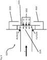
In dem beanspruchten Beatmungsgerät ist innerhalb des pneumatischen Schaltungssystems mindestens ein solcher Partikelfilter pneumatisch geschaltet, auf welchen mindestens eine Lichtquelle in einer Lichtemissionsrichtung ausgerichtet ist.In the ventilator claimed, at least one such particle filter is pneumatically switched within the pneumatic circuit system, to which at least one light source is aligned in a light emission direction.
Der Partikelfilter weist eine vordere Oberfläche und eine hintere Oberfläche auf, wobei der Partikelfilter in der Weise in dem pneumatischen Schaltungssystem pneumatisch geschaltet, dass beim Betrieb des beanspruchten Beatmungsgerätes der Fluss des Beatmungsgases in Durchflussrichtung zuerst die vordere Oberfläche und dann die hintere Oberfläche des Partikelfilters durchdringt. Somit entsprechen die vordere Oberfläche und die hintere Oberfläche im Wesentlichen oder ganz jeweils einem Strömungsquerschnitt. Eine solche Anordnung des Partikelfilters innerhalb des pneumatischen Schaltungssystems beruht auf einem ersten erfinderischen Gedanken, dass während des Flusses des Beatmungsgases durch den Partikelfilter Pathogene in ihrer Fließgeschwindigkeit abgebremst werden; hierbei ist es unerheblich, ob bei einem Fluss des Beatmungsgases durch den Partikelfilter die Pathogene vollständig oder teilweise oder gar nicht zurückgehalten werden. Allein durch die Abbremsung der Pathogene ist ein hinreichendes Zeitintervall gegeben, um durch Bestrahlung mit Licht die Pathogene teilweise oder vollständig abzutöten oder zumindest bezüglich ihrer Virulenz zu schwächen oder zu neutralisieren. Entscheidend ist also die Akkumulation von Pathogenen vor und auf der vorderen Oberfläche des Partikelfilters. Bei einem Durchdringen der hinteren Oberfläche durch Pathogene ist dagegen keine Akkumulation dieser gegeben, vielmehr resultiert ein Abtrag dieser durchgedrungenen Pathogene durch den Fluss des Beatmungsgases.The particle filter has a front surface and a rear surface, the particle filter being pneumatically switched in the pneumatic circuit system in such a way that, when the ventilator being claimed, the flow of the ventilation gas in the flow direction first penetrates the front surface and then the rear surface of the particle filter. Thus, the front surface and the rear surface correspond substantially or entirely to each Flow cross-section. Such an arrangement of the particle filter within the pneumatic circuit system is based on a first inventive concept that the flow rate of pathogens is slowed down while the ventilation gas is flowing through the particle filter; Here it is irrelevant whether the pathogens are completely or partially retained or not at all when the ventilation gas flows through the particle filter. By slowing down the pathogens alone, there is a sufficient time interval to partially or completely kill the pathogens through irradiation with light or at least to weaken or neutralize them with regard to their virulence. The decisive factor is the accumulation of pathogens in front of and on the front surface of the particle filter. In contrast, when pathogens penetrate the rear surface, there is no accumulation of these; rather, these penetrated pathogens are eroded by the flow of the ventilation gas.
Ein zweiter erfinderischer Gedanke ist bei dem vorgeschlagenen Beatmungsgerät daher durch die Ausrichtung mindestens einer Lichtquelle in einer Lichtemissionsrichtung auf den Partikelfilter in der Weise realisiert, dass in Durchflussrichtung zuerst die Lichtquelle und dann nachfolgend der Partikelfilter fest angeordnet ist. Somit ist innerhalb des pneumatischen Schaltungssystems eine Abstrahlung von Licht auf die vordere Oberfläche des Partikelfilters mittels der Lichtquelle bewerkstelligt. Dies resultiert in einer Bestrahlung sowohl der vorderen Oberfläche akkumulierten als auch auf der vorderen Oberfläche abgeschiedenen Pathogene in Lichtemissionsrichtung der Lichtquelle. Beispielsweise ist bei entsprechender Fertigung des Partikelfilters aus einem zumindest teilweise transluzenten Material ein Eindringen des durch die Lichtquellen abgestrahlten Lichtes durch die vordere Oberfläche ermöglicht, so dass auch Pathogene innerhalb des Partikelfilters zumindest teilweise durch Bestrahlung erfasst sind.A second inventive idea is therefore implemented in the proposed ventilator by aligning at least one light source in a light emission direction on the particle filter in such a way that first the light source and then subsequently the particle filter is fixed in the flow direction. Thus, within the pneumatic circuit system, light is emitted onto the front surface of the particle filter by means of the light source. This results in irradiation of both the front surface accumulated pathogens and pathogens deposited on the front surface in the light emission direction of the light source. For example, if the particle filter is manufactured accordingly from an at least partially translucent material, the light emitted by the light sources can penetrate through the front surface, so that pathogens within the particle filter are also at least partially captured by irradiation.
Bei dem vorgeschlagenen Beatmungsgerät ist es keinesfalls erforderlich, dass die Lichtquelle innerhalb der Verrohrung des pneumatischen Schaltungssystems angebracht ist. Es ist lediglich erforderlich, dass die Lichtemissionsrichtung der Lichtquelle auf die vordere Oberfläche des Partikelfilters ausgerichtet und eine Bestrahlung der vorderen Oberfläche sichergestellt ist. Beispielsweise ist dies auch durch ein hinreichend transparentes Lichtfenster realisierbar, welches in die Verrohrung vor der vorderen Oberfläche des Partikelfilters eingelassen ist. Ein solches Lichtfenster ist beispielsweise aus Quarz oder Saphir gefertigt. Beispielsweise ist auf dem Lichtfenster die Lichtquelle in der Weise fixiert, dass in Lichtemissionsrichtung eine Bestrahlung der vorderen Oberfläche des Partikelfilters ermöglicht ist. Bei der Vermeidung der Anordnung der Lichtquelle innerhalb der Verrohrung ist somit zugleich die Ausbildung eines nachteiligen Strömungswiderstandes eliminiert, so dass besonders vorteilhaft innerhalb der Verrohrung eine Laminarströmung des Beatmungsgases realisierbar ist. Weiter ist eine solche Vorrichtung besonders vorteilhaft bei mehrstückiger Fertigung der Verrohrung und einer Halterung der Lichtquelle so gestaltbar, dass für eine einfache Wartung oder allfällige Reparatur des beanspruchten Beatmungsgerätes die Lichtquelle einfach abnehmbar ist, ohne dass ein Öffnen der Verrohrung erforderlich ist.In the case of the proposed ventilator, it is by no means necessary for the light source to be attached within the piping of the pneumatic circuit system. It is only necessary that the light emission direction of the light source is aligned with the front surface of the particle filter and that irradiation of the front surface is ensured. For example, this can also be achieved by means of a sufficiently transparent light window which is let into the piping in front of the front surface of the particle filter. Such a light window is made of quartz or sapphire, for example. For example, the light source is fixed on the light window in such a way that the front surface of the particle filter can be irradiated in the light emission direction. In avoiding the arrangement of the light source within the piping, the formation of a disadvantageous flow resistance is thus eliminated at the same time, so that a laminar flow of the ventilation gas can be realized particularly advantageously within the piping. Furthermore, such a device is particularly advantageous in the case of multi-piece production of the piping and a holder of the light source so that the light source can be easily removed for simple maintenance or any repairs to the stressed ventilator without having to open the piping.
Das vorgeschlagene Beatmungsgerät beruht bezüglich des durch die Lichtquelle abgestrahlten Lichtes auf der Hierarchie gekoppelter Quantensysteme als dritten erfinderischen Gedanken. In Konsequenz daraus sind für jeden elektronischen Anregungszustand eines Moleküls oder eines Molekülaggregates jeweils ein Satz verschiedener Oszillatorzustände gegeben. Ein Pathogen, das heißt ein virulenter Mikroorganismus, entspricht prinzipiell einem Molekülaggregat. Wird durch eine elektronische Anregung durch Bestrahlung mit Licht, bei einem solchen Molekülaggregat ausgewählt aus einem ersten Wellenlängenbereich von 385 nm bis 780 nm, insbesondere aber aus einem ersten Wellenlängenbereich von 385 nm bis 425 nm, die Bindungsordnung einer chemischen Bindung herabgesetzt, so resultieren energetisch herabgesetzte Oszillatorzustände und damit energetisch herabgesetzte Dissoziationsenergien der betreffenden Bindung bei einem real gegeben Morse-Potential. Bei gleichzeitiger Einstrahlung von Infrarot-Strahlung (IR) ausgewählt aus einem zweiten Wellenlängenbereich von mehr als 780 nm bis 2000 nm ist somit eine beschleunigte Dissoziation der betreffenden Bindung realisierbar. Es hat sich bei Pathogenen experimentell gezeigt, dass bei einer Bestrahlung mit Licht, welches Licht sowohl aus dem ersten Wellenlängenbereich als auch aus dem zweiten Wellenlängenbereich enthält, eine beschleunigte Abtötung oder zumindest eine beschleunigte Inaktivierung von Pathogenen bezüglich deren Virulenz erzielbar ist.The proposed ventilator is based on the hierarchy of coupled quantum systems as a third inventive concept with regard to the light emitted by the light source. As a consequence, a set of different oscillator states is given for each electronic excitation state of a molecule or a molecular aggregate. A pathogen, i.e. a virulent microorganism, corresponds in principle to a molecular aggregate. If the bond order of a chemical bond is reduced by electronic excitation by irradiation with light, in the case of such a molecular aggregate selected from a first wavelength range from 385 nm to 780 nm, but in particular from a first wavelength range from 385 nm to 425 nm, the result is energetically reduced bonds Oscillator states and thus energetically reduced dissociation energies of the bond in question with a real Morse potential. With simultaneous irradiation of infrared radiation (IR) selected from a second wavelength range of more than 780 nm to 2000 nm, accelerated dissociation of the bond in question can thus be achieved. It has been shown experimentally with pathogens that when irradiated with light which contains light from both the first wavelength range and from the second wavelength range, an accelerated killing or at least an accelerated inactivation of pathogens with regard to their virulence can be achieved.
Bei einer Bestrahlung mit Licht nur aus dem ersten Wellenlängenbereich oder nur aus dem zweiten Wellenlängenbereich jeweils allein resultiert dagegen in einer signifikant langsameren Abtötung oder signifikant langsameren Inaktivierung von Pathogenen.Irradiation with light only from the first wavelength range or only from the second wavelength range alone, on the other hand, results in a significantly slower killing or significantly slower inactivation of pathogens.
Daher ist bei dem vorgeschlagenen Beatmungsgerät das auf den Partikelfilter abgestrahlte Licht aus einem ersten Wellenlängenbereich von 385 nm bis 780 nm (hinreichende Anregung von elektronischen Zuständen) und aus einem zweiten Wellenlängenbereich von mehr als 780 nm bis 1700 nm (entsprechend einer Anregung von Oszillatorzuständen) ausgewählt.Therefore, in the proposed ventilator, the light emitted onto the particle filter is selected from a first wavelength range from 385 nm to 780 nm (sufficient excitation of electronic states) and from a second wavelength range from more than 780 nm to 1700 nm (corresponding to an excitation of oscillator states) .
Nachfolgend wird auf vorteilhafte Weiterbildungen des vorgeschlagenen Beatmungsgerätes hinsichtlich einer Anordnung von Lichtquellen und deren Beschaffenheit näher eingegangen. Diese Weiterbildungen entsprechen schrittweisen Optimierungen des beanspruchten Beatmungsgerätes bezüglich Intensität und Effizienz der Beleuchtung des Partikelfilters.In the following, advantageous developments of the proposed ventilator with regard to an arrangement of light sources and their properties will be discussed in greater detail. These developments correspond to step-by-step optimizations of the ventilator used in terms of intensity and efficiency of the lighting of the particle filter.
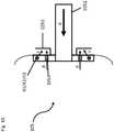
In einer ersten Weiterbildung der Erfindung bezüglich der Lichtquellen ist jeweils beidseitig zu dem Partikelfilter mindestens eine Lichtquelle angeordnet. Somit ist auf den Partikelfilter auch auf dessen hintere Oberfläche mindestens eine Lichtquelle in deren Lichtemissionsrichtung ausgerichtet, wodurch besonders vorteilhaft eine Nachbehandlung von den Partikelfilter durchdringenden Pathogenen durch Bestrahlung mit Licht ermöglicht ist. Ist beispielsweise hierbei der Partikelfilter nicht nur aus einem transluzenten Material gefertigt, sondern weisen auch dessen vordere und dessen hintere Oberfläche eine hinreichend geringe Distanz zueinander auf, ist besonders vorteilhaft zusätzlich bei einer hinreichenden Bestrahlungsleistung der Lichtquelle eine Bestrahlung über die gesamte Distanz zwischen hinterer und vorderer Oberfläche ermöglicht.In a first development of the invention with regard to the light sources, at least one light source is arranged on both sides of the particle filter. Thus, at least one light source is aligned on the particle filter also on its rear surface in its light emission direction, whereby a post-treatment of pathogens penetrating the particle filter by irradiation with light is particularly advantageously possible. If, for example, the particle filter is not only made of a translucent material, but its front and rear surfaces are also sufficiently small, irradiation over the entire distance between the rear and front surface is particularly advantageous if the light source has sufficient irradiation power enables.
In einer zweiten Weiterbildung der Erfindung bezüglich der Lichtquellen ist der Partikelfilter auf Seite der Lichtquelle flächenvollständig ausleuchtbar. Dies ist bereits jeweils mit einer Lichtquelle beispielsweise dadurch bewerkstelligbar, dass diese zur Emission von Licht in geometrischer Form eines Lichtkegels mit einem hinreichend großen Lichtkegelwinkel ausgebildet ist. Somit ist eine Bestrahlung aller Pathogene ermöglicht, welche beim Betreib des vorgeschlagenen Beatmungsgerätes auf die vordere Oberfläche des Partikelfilters und/oder durch dessen hintere Oberfläche mit dem Fluss des Beatmungsgases austreten.In a second development of the invention with regard to the light sources, the particle filter can be completely illuminated on the side of the light source. This can already be achieved with one light source, for example, in that it is designed to emit light in the geometric shape of a light cone with a sufficiently large light cone angle. This enables all pathogens to be irradiated which, when the proposed ventilator is operated, emerge on the front surface of the particle filter and / or through its rear surface with the flow of the ventilation gas.
In einer dritten Weiterbildung der Erfindung bezüglich der Lichtquellen ist der Partikelfilter umlaufend gleichmäßig mit mindestens einer Lichtquelle ausleuchtbar. Dies ist beispielsweise dadurch mit einer einzigen Lichtquelle bewerkstelligbar, indem deren Emissionsfläche selbst umlaufend, in sich geschlossen und nach innen abgewinkelt ausgebildet ist. Beispielsweise ist ein umlaufendes, in sich geschlossenes Lichtfenster in die Verrohrung eingelassen, über welches eine Lichtquelle mit einer umlaufenden, in sich geschlossenen und nach innen abgewinkelten Emissionsfläche geschoben und fixiert ist. Alternativ zu einer Lichtquelle sind beispielsweise mehrere Lichtquellen in jeweils gleichen Abständen zueinander um den Partikelfilter angeordnet. Durch eine gleichmäßige Ausleuchtung der vorderen und/oder hinteren Oberfläche des Partikelfilters ist gewährleistet, dass alle auf den Partikelfilter auftreffenden oder durch den Partikelfilter durchtretenden Pathogene einer gleichen oder zumindest annähernd gleichen Strahlungsdichte des durch die Lichtquelle oder Lichtquellen emittierten Lichtes ausgesetzt sind.In a third development of the invention with regard to the light sources, the particle filter can be uniformly illuminated all around with at least one light source. This can be achieved, for example, with a single light source in that its emission surface itself is designed to be circumferential, closed in itself and angled inward. For example, a circumferential, self-contained light window is let into the piping, over which a light source with a circumferential, self-contained and inwardly angled emission surface is pushed and fixed. As an alternative to one light source, for example, several light sources are arranged around the particle filter at equal distances from one another. Uniform illumination of the front and / or rear surface of the particle filter ensures that all pathogens that hit the particle filter or pass through the particle filter are exposed to the same or at least approximately the same radiation density of the light emitted by the light source or light sources.
Mit einer Lichtquelle, welche beispielsweise zur Abstrahlung von Licht in einem Wellenlängenintervall von 385 nm bis 1700 nm, bevorzugt bis 2000 nm ausgebildet ist und nur ein einziges Emissionsmaximum aufweist, ist eine zumindest annähernd gleichmäßige Anregung sowohl von Elektronenzuständen als auch von Oszillatorzuständen nur dann erreichbar, wenn sich das Emissionsmaximum zwischen dem Wellenlängenbereich der Anregungen von Elektronenzuständen und dem Wellenlängenbereich der Anregungen von Oszillatorzuständen befindet. Für eine hinreichend hohe Anregung erfordert dies eine Lichtquelle mit einer sehr hohen Leistungsstärke.With a light source, which is designed, for example, to emit light in a wavelength interval of 385 nm to 1700 nm, preferably up to 2000 nm and has only a single emission maximum, an at least approximately uniform excitation of both electron states and oscillator states can only be achieved if when the emission maximum is located between the wavelength range of the excitations of electronic states and the wavelength range of the excitations of oscillator states. For a sufficiently high excitation, this requires a light source with a very high power level.
Ist zur Bestrahlung des Partikelfilters nur eine Sorte von Lichtquellen zur Abstrahlung von Licht in einem Wellenlängenintervall von 385 nm bis 2000 nm vorgesehen und dementsprechend ausgebildet, so weisen Lichtquellen dieser Sorte daher vorzugsweise sowohl im ersten Wellenlängenbereich der Anregungen von Elektronenzuständen als auch im zweiten Wellenlängenbereich der Anregungen von Oszillatorzuständen jeweils mindestens ein Emissionsmaximum auf. Das heißt, dass eine Lichtquelle dieser Sorte über ein Wellenlängenintervall von 385 nm bis 2000 nm insgesamt mindestens zwei Emissionsmaxima aufweist. Mit Lichtquellen einer solchen Sorte ist schon mit einer vergleichsweisen geringen Leistungsstärke eine zumindest annähernd gleichmäßige Anregung sowohl von Elektronenzuständen als auch von Oszillatorzuständen und damit effiziente Abtötung und/oder Inaktivierung von Pathogenen erreichbar.If only one type of light source for the emission of light in a wavelength interval of 385 nm to 2000 nm is provided for irradiating the particle filter and is designed accordingly, light sources of this type therefore preferably have both the first wavelength range of the excitations of electronic states and the second wavelength range of the excitations of oscillator states each have at least one emission maximum. This means that a light source of this type has a total of at least two emission maxima over a wavelength interval from 385 nm to 2000 nm. With light sources of this type, even with a comparatively low power level, an at least approximately uniform excitation of both electronic states and oscillator states and thus efficient killing and / or inactivation of pathogens can be achieved.
In einer vierten Weiterbildung der Erfindung bezüglich der Lichtquellen sind auf den Partikelfilter mehrere Sorten von Lichtquellen umlaufend in alternierender Reihenfolge bezüglich der Sorten von Lichtquellen ausgerichtet. Hierbei unterscheiden sich die Sorten von Lichtquellen durch das jeweils abgestrahlte Licht. Dies gestattet besonders vorteilhaft die Wahl und Kombination solcher Lichtquellen, deren jeweils abgestrahltes Licht bezüglich Wellenlängenintervall und/oder Emissionsmaximum auf die Anregung von Elektronenzuständen und/oder von Oszillatorzuständen abgestimmt ist. Somit ist es auch ermöglicht, die Beleuchtung des Partikelfilters bezüglich der Abtötung und/oder Inaktivierung spezifischer Pathogene, wie beispielsweise MRSA, gezielt anzupassen. Durch eine Anordnung verschiedener Sorten von Lichtquellen umlaufend um den Partikelfilter und in alternierender Reihenfolge ist flächenvollständige und gleichmäßige Ausleuchtung des Partikelfilters leicht realisierbar.In a fourth development of the invention with regard to the light sources, several types of light sources are aligned on the particle filter in an alternating sequence with regard to the types of light sources. The types of light sources differ in the light emitted in each case. This particularly advantageously allows the selection and combination of such light sources, the light emitted in each case with respect to the wavelength interval and / or emission maximum being matched to the excitation of electron states and / or oscillator states. It is thus also possible to specifically adapt the illumination of the particle filter with regard to the killing and / or inactivation of specific pathogens, such as MRSA, for example. By arranging different types of light sources circumferentially around the particle filter and in alternating sequence, it is easy to achieve a uniform and complete illumination of the particle filter.
In einer fünften Weiterbildung der Erfindung bezüglich der Lichtquellen ist eine Sorte solcher Lichtquellen gegeben, welche zur Abstrahlung mit einem Emissionsmaximum von 405 nm ausgebildet sind. Bezüglich der elektronischen Anregung einer großen Typenvielfalt von Pathogenen hat sich die Bestrahlung mit Licht einer Wellenlänge von 405 nm als Optimum erwiesen. Hierfür besonders leistungsfähige Lichtquellen sind zur Abstrahlung von Licht in einem auf 385 nm bis 425 nm begrenzten Wellenlängenintervall mit einem Emissionsmaximum von 405 nm ausgebildet.
In einer sechsten Weiterbildung der Erfindung bezüglich der Lichtquellen umfasst das abgestrahlte Licht aller Lichtquellen ein Wellenlängenkontinuum von 385 nm bis 2000 nm. Hierdurch ist die Anregung aller Elektronen und Oszillatorzustände sichergestellt. Dies ist beispielsweise durch drei Sorten von Lichtquellen realisiert, wobei jeweils
- - die Lichtquellen der ersten Sorte zur Abstrahlung von Licht in einem auf 385 nm bis 425 nm begrenzten Wellenlängenintervall mit einem Emissionsmaximum von 405 nm,
- - die Lichtquellen der zweiten Sorte zur Abstrahlung von Licht in einem auf 385 nm bis 1000 nm begrenzten Wellenlängenintervall mit einem Emissionsmaximum von 600 nm und
- - die Lichtquellen der dritten Sorte zur Abstrahlung von Licht in einem auf 900 nm bis 2000 nm begrenzten Wellenlängenintervall mit einem ersten Emissionsmaximum von 1400 nm und einem zweiten Emissionsmaximum von 1600 nm ausgebildet sind.
In a sixth development of the invention with regard to the light sources, the emitted light from all light sources comprises a wavelength continuum from 385 nm to 2000 nm. This ensures the excitation of all electrons and oscillator states. This is implemented, for example, by three types of light sources, each with
- - the light sources of the first type for the emission of light in a wavelength interval limited to 385 nm to 425 nm with an emission maximum of 405 nm,
- - The light sources of the second type for the emission of light in a wavelength interval limited to 385 nm to 1000 nm with an emission maximum of 600 nm and
- - The light sources of the third type are designed for the emission of light in a wavelength interval limited to 900 nm to 2000 nm with a first emission maximum of 1400 nm and a second emission maximum of 1600 nm.
Nachfolgend wird auf vorteilhafte Ausführungsformen des vorgeschlagenen Beatmungsgerätes hinsichtlich des Partikelfilters näher eingegangen. Das vorgeschlagene Beatmungsgerät ist keinesfalls auf einen in dem pneumatischen Schaltungssystem angeordneten Partikelfilter, insbesondere auf einen oder mehrere Partikelfilter von nur einer Sorte, beschränkt. Das vorgeschlagene Beatmungsgerät ist auch keinesfalls auf in dem pneumatischen Schaltungssystem angeordnete Partikelfilter beschränkt, auf welche jeweils mindestens eine Lichtquelle in einer Lichtemissionsrichtung ausgerichtet ist. Die Anzahl und Beschaffenheit der Partikelfilter ist allein durch eine zu wahrende Baugröße des beanspruchten Beatmungsgerätes und durch die Vorgabe eines maximalen gesamten Flusswiderstandes von beispielsweise bis zu 5 hPa min 120-1 L-1 festgelegt.Advantageous embodiments of the proposed ventilator with regard to the particle filter are discussed in greater detail below. The proposed ventilator is in no way limited to a particle filter arranged in the pneumatic circuit system, in particular to one or more particle filters of only one type. The proposed ventilator is in no way limited to particle filters arranged in the pneumatic circuit system, to which at least one light source is aligned in a light emission direction. The number and nature of the particle filters is determined solely by the size of the ventilator being used and by specifying a maximum total flow resistance of, for example, up to 5 hPa min 120-1 L-1 .
In einer ersten Ausführungsform der Erfindung bezüglich des Partikelfilters ist der Partikelfilter als Glasfritte oder als Pressling aus Glaswolle und/oder zum Rückhalt von Pathogenen ausgebildet. Eine Glasfritte oder ein Pressling aus Glaswolle ist besonders vorteilhaft durch Autoklavierung bei mehr als 130° C sterilisierbar und damit wiederverwendbar. Durch Wahl einer Porengröße des Partikelfilters ist eine Größenselektivität bezüglich des Rückhaltes von spezifischen Mikroorganismen und damit Pathogenen, beispielsweise Bakterien, Pilze und Viren, einstellbar. Durch Wahl eines Filtermaterials, beispielsweise Teflon oder Nylon oder eines hydrophoben oder hydrophilen Kunststoffes in Faserform, ist ebenfalls eine Typenselektivität des Partikelfilters bezüglich des Rückhaltes von spezifischen Mikroorganismen alternativ oder zusätzlich optimierbar. Partikelfilter verschiedenster Porengrößen und gefertigt aus verschiedensten Materialien zum Rückhalt von Partikeln und/oder Mikroorganismen sind im Handel kommerziell erhältlich. Durch einen dauerhaften Rückhalt von Partikeln und/oder Mikroorganismen in dem Partikelfilter ist die Desinfektion des Beatmungsgases zusätzlich verbessert.In a first embodiment of the invention with regard to the particle filter, the particle filter is designed as a glass frit or as a pellet made of glass wool and / or for the retention of pathogens. A glass frit or a pellet made of glass wool can be sterilized particularly advantageously by autoclaving at more than 130 ° C and can therefore be reused. By choosing a pore size of the particle filter, a size selectivity with regard to the retention of specific microorganisms and thus pathogens, for example bacteria, fungi and viruses, can be set. By choosing a filter material, for example Teflon or nylon or a hydrophobic or hydrophilic plastic in fiber form, a type selectivity of the particle filter with regard to the retention of specific microorganisms can alternatively or additionally be optimized. Particle filters of various pore sizes and made of various materials to retain particles and / or microorganisms are commercially available. Permanent retention of particles and / or microorganisms in the particle filter also improves the disinfection of the ventilation gas.
In einer weiteren Variante der zweiten Ausführungsform der Erfindung bezüglich des Partikelfilters weist die Glasfritte eine Porenweite von 1 Dm bis 200 Dm, bevorzugt 2 bis 150 µm auf. Eine solche Glasfritte weist keinen merklichen Flusswiderstand auf, ohne dass die Akkumulation von Mikroorganismen vor und auf der vorderen Oberfläche der Glasfritte beeinträchtigt ist.In a further variant of the second embodiment of the invention with regard to the particle filter, the glass frit has a pore size of 1 μm to 200 μm, preferably 2 to 150 μm. Such a glass frit does not have any noticeable flow resistance without the accumulation of microorganisms in front of and on the front surface of the glass frit being impaired.
In einer dritten Ausführungsform der Erfindung bezüglich des Partikelfilters sind in dem pneumatischen Schaltungssystem mehrere Partikelfilter mit in Durchflussrichtung jeweils abnehmender Porengröße angeordnet. Mit einer solchen kombinierten Anordnung ist ein Optimum an Verwendungsdauer der Partikelfilter gewährleistet, bis ein Auswechseln dieser aufgrund von Sättigung mit Partikeln und Mikroben erforderlich ist.In a third embodiment of the invention with regard to the particle filter, a plurality of particle filters, each with a pore size decreasing in the flow direction, are arranged in the pneumatic circuit system. With such a combined arrangement, an optimum period of use of the particle filters is guaranteed until they have to be replaced due to saturation with particles and microbes.
In manchen Ausführungsformen der Erfindung erfolgt die Energieversorgung der Lichtquellen über das Netzteil des Beatmungsgeräts. Dazu sind die Lichtquellen beispielsweise in das interne Stromnetz des Beatmungsgeräts integriert. Diese Integration ermöglicht beispielsweise auch den Betrieb der Lichtquellen in dem Fall, dass das Beatmungsgerät über einen Akku mit Energie versorgt wird.In some embodiments of the invention, the light sources are supplied with energy via the power supply unit of the ventilator. For this purpose, the light sources are integrated into the internal power supply of the ventilator, for example. This integration also enables, for example, the operation of the light sources in the event that the ventilator is supplied with energy via a battery.
In manchen Ausführungsformen erfolgt die Energieversorgung der Lichtquellen über eine - bezogen auf das Beatmungsgerät - externe Energiequelle. So können die Lichtquellen zum Beispiel mit einem eigenen Netzteil oder Akkus bzw. Batterien verbunden werden. Insbesondere für den erfindungsgemäßen Adapter ist die Verbindung mit einer externen Energieversorgung denkbar. Eine Verbindung der Lichtquellen mit einer externen Energiequelle ist aber auch bei Lichtquellen denkbar, welche in dem Beatmungsgerät verbaut sind.In some embodiments, the light sources are supplied with energy via an energy source that is external to the ventilator. For example, the light sources can be connected to their own power supply unit or rechargeable batteries or batteries. Connection to an external power supply is conceivable in particular for the adapter according to the invention. A connection of the light sources to an external energy source is also conceivable in the case of light sources that are built into the ventilator.
In weiteren Ausführungsformen der Erfindung sind die Lichtquellen schaltbar, d.h. aktivierbar und deaktivierbar, eingerichtet. Beispielsweise sind die Lichtquellen mit einem Schalter verbunden, welcher die Energieversorgung zum Beispiel unterbrechen kann, die Lichtquellen also ausschalten bzw. deaktivieren kann. Ein solcher Schalter ist so eingerichtet, dass auch eine (erneute) Aktivierung bzw. ein Einschalten der Lichtquellen ermöglicht wird. Ein solcher Lichtschalter kann beispielsweise in das Gehäuse des Beatmungsgeräts integriert sein aber auch als extra Schalter ausgeführt sein. Der erfindungsgemäße Adapter verfügt beispielsweise über einen vom Beatmungsgerät unabhängigen Schalter.In further embodiments of the invention, the light sources can be switched, ie activated and can be deactivated, set up. For example, the light sources are connected to a switch that can interrupt the energy supply, for example, that is to say can switch off or deactivate the light sources. Such a switch is set up in such a way that (renewed) activation or switching on of the light sources is also possible. Such a light switch can for example be integrated into the housing of the ventilator, but can also be designed as an extra switch. The adapter according to the invention has, for example, a switch that is independent of the ventilator.
In einer weiteren Ausführungsform sind die Lichtquellen so eingerichtet, dass sie durch eine nicht näher beschriebene Kontrolleinheit in ihrer Leuchtstärke variierbar (zum Beispiel durch Anpassen der Betriebsspannung der Lichtquellen) sind, also dimmbar sind. Darunter ist auch zu verstehen, dass die Leuchtstärke bzw. die Betriebsspannung der Lichtquellen soweit runtergeregelt werden kann, dass die Lichtquellen ausgeschaltet sind.In a further embodiment, the light sources are set up in such a way that their luminosity can be varied (for example by adapting the operating voltage of the light sources), that is to say can be dimmed, by a control unit which is not described in detail. This also means that the luminosity or the operating voltage of the light sources can be regulated down to such an extent that the light sources are switched off.
In einer Ausführungsform sind die Lichtquellen so eingerichtet und in das Beatmungsgerät integriert, dass diese durch ein Steuersystem des Beatmungsgeräts ein- und ausgeschalten werden können bzw. auch die Leuchtstärke variiert werden kann. Dadurch kann beispielsweise eine automatische Abschaltung der Lampen bei Umstellung des Beatmungsgeräts von Netz- auf Akkubetrieb eingerichtet werden.In one embodiment, the light sources are set up and integrated into the ventilator in such a way that they can be switched on and off by a control system of the ventilator or the light intensity can also be varied. In this way, for example, the lamps can be switched off automatically when the ventilator is switched from mains to battery operation.
Das beanspruchte Beatmungsgerät weist im Vergleich zu solchen nach dem Stand der Technik folgende Vorteile auf:
- - Das durch die Lichtquellen abgestrahlte Licht ist bezüglich der Wellenlängen weder für das Fertigungsmaterial der Verrohrung noch für Menschen und Säugetiere schädlich.
- - Bei dem vorgeschlagenen Beatmungsgerät entfallen damit technisch aufwändige Maßnahmen zum Schutz vor schädlicher elektromagnetischer Strahlung und zur Ableitung von überschüssiger Wärme.
- - Bei einem abgestrahlten Licht in einem Wellenlängenbereich von 385 nm bis 2000 nm ist keine Bildung von toxischen Substanzen aus dem Beatmungsgas gegeben, selbst wenn dieses ein Inhalationsanästhetikum wie beispielsweise wie Halothan, Isofluran, Sevofluran und Desfluran enthält.
- - Hinsichtlich einfacher Fertigung, wirtschaftlichem Betrieb, Hygiene und Betriebssicherheit ist das vorgeschlagene Beatmungsgerät gegenüber dem Stand der Technik wesentlich verbessert.
- - In terms of wavelengths, the light emitted by the light sources is neither harmful to the manufacturing material of the piping nor to humans and mammals.
- - In the proposed ventilator, technically complex measures for protection against harmful electromagnetic radiation and for dissipating excess heat are no longer necessary.
- - With emitted light in a wavelength range from 385 nm to 2000 nm, there is no formation of toxic substances from the ventilation gas, even if this contains an inhalation anesthetic such as halothane, isoflurane, sevoflurane and desflurane.
- With regard to simple production, economical operation, hygiene and operational safety, the proposed ventilator is significantly improved over the prior art.
Die Bereitstellung eines Adapters für Beatmungsgeräte bietet darüber hinaus den Vorteil, Beatmungsgeräte ohne die beschriebenen Merkmale der Erfindung kostengünstig mit ebenjenen Merkmalen aufzurüsten. Der vorgeschlagene Adapter umfasst die gleichen Merkmale wie das vorgeschlagene Beatmungsgerät, kann dazu nachträglich oder zusätzlich an ein Beatmungsgerät angebracht bzw. angeschlossen werden.The provision of an adapter for ventilators also offers the advantage of inexpensively upgrading ventilators without the described features of the invention with the same features. The proposed adapter includes the same features as the proposed ventilator and can be attached or connected to a ventilator subsequently or in addition.
Die Begriffe Pathogene, Keime, Mikroorganismen werden in dieser Anmeldung als Synonyme verwendet, um insbesondere aber nicht ausschließlich beispielsweise Viren, Bakterien, Pilze zu bezeichnen.The terms pathogens, germs, and microorganisms are used as synonyms in this application in order to denote, in particular, but not exclusively, viruses, bacteria, fungi, for example.
Nachfolgend wird das vorgeschlagene Beatmungsgerät anhand einer Zeichnung näher erläutert. Hierin zeigt:
1 Das beanspruchte Beatmungsgerätes 1 in schematischer Teilansicht eines pneumatischen Schaltungssystems2 im Längsschnitt;2 Querschnitt durchdas pneumatische Schaltungssystem 2 .
1 The claimedventilator 1 in a schematic partial view of apneumatic circuit system 2 in longitudinal section;2 Cross section through thepneumatic circuit system 2 .
In dem nachfolgenden Ausführungsbeispiel ist das beanspruchte Beatmungsgerät
Innerhalb des pneumatischen Schaltungssystems
Die
In die Verrohrung
In der
Der Partikelfilter
Die
- - die Lichtquellen der ersten Sorte
41 zur Abstrahlung von Licht in einem auf 385 nm bis 425 nm begrenzten Wellenlängenintervall mit einem Emissionsmaximum von 405 nm, - - die Lichtquellen der zweiten Sorte
42 zur Abstrahlung von Licht in einem auf 385 nm bis 1000 nm begrenzten Wellenlängenintervall mit einem Emissionsmaximum von 600 oder 630 nm und - - die Lichtquellen der dritten Sorte
43 zur Abstrahlung von Licht in einem auf 900 nm bis 1700 oder 2000 nm begrenzten Wellenlängenintervall mit einem ersten Emissionsmaximum von 1300 oder 1400 nm und einem zweiten Emissionsmaximum von 1550 oder 1600 nm ausgebildet.
- - the light sources of the
first kind 41 for the emission of light in a wavelength interval limited to 385 nm to 425 nm with an emission maximum of 405 nm, - - the light sources of the
second kind 42 for the emission of light in a wavelength interval limited to 385 nm to 1000 nm with an emission maximum of 600 or 630 nm and - - the light sources of the
third kind 43 designed for the emission of light in a wavelength interval limited to 900 nm to 1700 or 2000 nm with a first emission maximum of 1300 or 1400 nm and a second emission maximum of 1550 or 1600 nm.
Hierdurch ist die Anregung aller Elektronen und Oszillatorzustände der Mikroorganismen sichergestellt.This ensures that all electrons and oscillator states of the microorganisms are excited.
In
Die
In
In den
Die Prallfläche
In
In einer weiteren, nicht näher gezeigten Ausführungsform ist beispielsweise statt einer Prallfläche
Erfindungsgemäß können auch auf der Prallfläche Partikelfilter angeordnet sein.
Die Partikelfilter sind in allen Ausführungsbeispielen eingerichtet und ausgebildet Keime (Viren, Bakterien, Pilze) zumindest teilweise zurück zu halten. Die sind in allen Ausführungsbeispielen beispielsweise zudem eingerichtet und ausgebildet das erfindungsgemäße Licht zumindest teilweise weiterzuleiten oder in tiefere Schichten des Filters eindringen zu lassen.According to the invention, particle filters can also be arranged on the baffle.
In all exemplary embodiments, the particle filters are set up and designed to at least partially hold back germs (viruses, bacteria, fungi). In all of the exemplary embodiments, they are also set up and designed to at least partially transmit the light according to the invention or to allow it to penetrate deeper layers of the filter.
Es ist zu verstehen, dass die Anzahl und Anordnung der Lichtquellen sowie der Prallfläche hauptsächlich beispielhaft das Funktionsprinzip wiedergeben sollen und sowohl Lichtquellen als auch Prallfläche in verschiedener Anzahl, Anordnung und Form möglich ist.It should be understood that the number and arrangement of the light sources and the baffle are mainly intended to represent the functional principle by way of example, and that both light sources and baffle are possible in various numbers, arrangements and shapes.
In einer weiteren beispielhaften Ausführungsform ist es möglich auf die Lichtquellen auf Seite des Ausgangs
In
In
BezugszeichenlisteList of reference symbols
- 11
- BeatmungsgerätVentilator
- 101101
- LuftzufuhrAir supply
- 102102
- AtemgasabfuhrBreathing gas evacuation
- 103103
- AnzeigeflächeDisplay area
- 105105
- PatienteninterfacePatient interface
- 106106
- GasflussleitungGas flow line
- 107107
- GasflussleitungGas flow line
- 10211021
- PrallflächeBaffle
- 10221022
- LichtquellengehäuseLight source housing
- 10231023
- Mantelcoat
- 10241024
- Verbindungenlinks
- 10251025
- Ausgangoutput
- 10311031
- LichtquellengehäuseLight source housing
- 10321032
- Schirmumbrella
- 10511051
- Abdeckungcover
- 10521052
- GaszuleitungGas supply line
- 10531053
- AusströmöffnungOutlet opening
- 22
- pneumatisches Schaltungssystempneumatic switching system
- 2121st
- VerrohrungPiping
- 2222nd
- LichtfensterLight window
- 3131
- PartikelfilterParticle filter
- 3232
- PartikelfilterParticle filter
- 3333
- PartikelfilterParticle filter
- 310310
- vordere Oberflächefront surface
- 320320
- vordere Oberflächefront surface
- 330330
- vordere Oberflächefront surface
- 311311
- hintere Oberflächeposterior surface
- 321321
- hintere Oberflächeposterior surface
- 331331
- hintere Oberflächeposterior surface
- 4141
- Lichtquelle einer ersten SorteLight source of a first kind
- 4242
- Lichtquelle einer zweiten SorteA second kind of light source
- 4343
- Lichtquelle einer dritten SorteLight source of a third kind
- 66th
- Adapteradapter
- dd
- DurchflussrichtungFlow direction
- rr
- LichtemissionsrichtungLight emission direction
ZITATE ENTHALTEN IN DER BESCHREIBUNGQUOTES INCLUDED IN THE DESCRIPTION
Diese Liste der vom Anmelder aufgeführten Dokumente wurde automatisiert erzeugt und ist ausschließlich zur besseren Information des Lesers aufgenommen. Die Liste ist nicht Bestandteil der deutschen Patent- bzw. Gebrauchsmusteranmeldung. Das DPMA übernimmt keinerlei Haftung für etwaige Fehler oder Auslassungen.This list of the documents listed by the applicant was generated automatically and is included solely for the better information of the reader. The list is not part of the German patent or utility model application. The DPMA assumes no liability for any errors or omissions.
Zitierte PatentliteraturPatent literature cited
- US 20160271288 A1 [0004]US 20160271288 A1 [0004]
- WO 2017023783 A1 [0004]WO 2017023783 A1 [0004]
- WO 2014159874 A1 [0005]WO 2014159874 A1 [0005]
- WO 2012052908 A1 [0005]WO 2012052908 A1 [0005]
- WO 2015092695 A1 [0005]WO 2015092695 A1 [0005]
- DE 10107443 A1 [0005]DE 10107443 A1 [0005]
- CN 204233560 U [0005]CN 204233560 U [0005]
Claims (19)
Translated fromGermanApplications Claiming Priority (2)
| Application Number | Priority Date | Filing Date | Title |
|---|---|---|---|
| DE102019110740.7 | 2019-04-25 | ||
| DE102019110740 | 2019-04-25 |
Publications (1)
| Publication Number | Publication Date |
|---|---|
| DE102020109727A1true DE102020109727A1 (en) | 2020-10-29 |
Family
ID=70333759
Family Applications (1)
| Application Number | Title | Priority Date | Filing Date |
|---|---|---|---|
| DE102020109727.1APendingDE102020109727A1 (en) | 2019-04-25 | 2020-04-07 | Ventilator |
Country Status (4)
| Country | Link |
|---|---|
| US (1) | US20200338297A1 (en) |
| EP (1) | EP3730158B1 (en) |
| CN (1) | CN111840718A (en) |
| DE (1) | DE102020109727A1 (en) |
Families Citing this family (3)
| Publication number | Priority date | Publication date | Assignee | Title |
|---|---|---|---|---|
| US11305032B2 (en)* | 2020-05-29 | 2022-04-19 | Stanley W. Ellis | Ultraviolet air irradiation system and ultraviolet air irradiation process |
| TR202106861A2 (en)* | 2021-04-20 | 2021-06-21 | Afyon Kocatepe Ueniversitesi Rektoerluegue | UV-C STERILIZER TO PREVENT CONTAMINATION OF AEROSOL VIRUS (COVID-19) SOURCED MECHANICAL VENTILATOR |
| DE102024135185A1 (en)* | 2023-12-05 | 2025-06-05 | Löwenstein Medical Technology S.A. | Germ protection device in a ventilation system |
Family Cites Families (23)
| Publication number | Priority date | Publication date | Assignee | Title |
|---|---|---|---|---|
| US3126003A (en)* | 1964-03-24 | Filter | ||
| FR2244548B1 (en)* | 1973-09-22 | 1978-03-31 | Original Hanau Quarzlampen | |
| US5855203A (en)* | 1997-12-19 | 1999-01-05 | Matter; Jean-Paul | Respiratory circuit with in vivo sterilization |
| DE10107443A1 (en) | 2001-02-16 | 2002-08-29 | Heptec Gmbh | Fresh air disinfection process, air disinfection module and flash lamps |
| US9625065B2 (en)* | 2004-09-03 | 2017-04-18 | Loewenstein Medical Technology S.A. | Plastics for medical technical devices |
| US20060177356A1 (en)* | 2005-02-08 | 2006-08-10 | Miller Gregory R | Positive pressure air purification and conditioning system |
| US20070163588A1 (en)* | 2005-11-08 | 2007-07-19 | Jack Hebrank | Respirators for Delivering Clean Air to an Individual User |
| US8003058B2 (en)* | 2006-08-09 | 2011-08-23 | Airinspace B.V. | Air purification devices |
| AU2010273182B2 (en)* | 2009-07-17 | 2016-01-28 | CleanSpace IP Pty Ltd | Respirator |
| WO2012052908A1 (en) | 2010-10-18 | 2012-04-26 | Etview Ltd. | Tracheal tube |
| DE102012010676A1 (en)* | 2012-05-31 | 2013-12-05 | Dräger Medical GmbH | Apparatus for use in a medical treatment room |
| US10293065B2 (en) | 2013-03-14 | 2019-05-21 | Teleflex Medical Incorporated | Optical fiber based antimicrobial ultraviolet radiation therapy system |
| CN203291337U (en)* | 2013-05-30 | 2013-11-20 | 史皆然 | Continuous purification disinfection device for pipeline of ventilator in working state |
| EP3082919B1 (en) | 2013-12-18 | 2019-05-29 | Koninklijke Philips N.V. | Gas delivery system and method of sanitizing the gas flow path within a gas delivery system |
| DE102014014661B4 (en)* | 2014-10-08 | 2022-10-13 | Drägerwerk AG & Co. KGaA | Device for removing and transporting a flow of breathing gas |
| CN204233560U (en) | 2014-10-11 | 2015-04-01 | 邱杨清 | A kind of anesthesia respirator with sterilization condensation exhaust pipeline |
| CN204134386U (en)* | 2014-10-14 | 2015-02-04 | 浙江成致气动科技有限公司 | A kind of air cleaner |
| US9457121B1 (en) | 2015-03-17 | 2016-10-04 | Matthew Phillip Davis | Ultraviolate light sterilization apparatus |
| US10960090B2 (en)* | 2015-03-18 | 2021-03-30 | Current Lighting Solutions, Llc | Light disinfection system and method |
| US10870015B2 (en)* | 2015-04-30 | 2020-12-22 | Light Line Medical, Inc. | Methods and apparatus to deliver therapeutic non-ultraviolet electromagnetic radiation for an endotracheal tube |
| WO2017023783A1 (en) | 2015-07-31 | 2017-02-09 | Garrett Kurt A | Systems and methods of microbial sterilization using polychromatic light |
| CN205936897U (en)* | 2016-05-26 | 2017-02-08 | 温州永清汽车过滤器有限公司 | Vehicle air cleaner |
| WO2018074864A1 (en)* | 2016-10-19 | 2018-04-26 | Samsung Electronics Co., Ltd. | Photocatalyst filter and air conditioner including the same |
- 2020
- 2020-04-07DEDE102020109727.1Apatent/DE102020109727A1/enactivePending
- 2020-04-16EPEP20000156.8Apatent/EP3730158B1/enactiveActive
- 2020-04-22USUS16/855,136patent/US20200338297A1/enactivePending
- 2020-04-23CNCN202010326514.1Apatent/CN111840718A/enactivePending
Also Published As
| Publication number | Publication date |
|---|---|
| CN111840718A (en) | 2020-10-30 |
| EP3730158B1 (en) | 2022-01-12 |
| EP3730158A1 (en) | 2020-10-28 |
| US20200338297A1 (en) | 2020-10-29 |
Similar Documents
| Publication | Publication Date | Title |
|---|---|---|
| EP3730158B1 (en) | Breathing apparatus | |
| EP0915713A1 (en) | Method and device for sheer filtering and desinfection of breathing air | |
| DE102020106235B3 (en) | RESPIRATORY MASK | |
| DE102020120046A1 (en) | Device for disinfecting air | |
| DE102012008253A1 (en) | Dryers, especially hand dryers | |
| DE102020119225B3 (en) | Device for disinfecting indoor air | |
| DE202020104775U1 (en) | Respiratory protection device | |
| DE102021000458A1 (en) | Air sterilizer | |
| DE102011001094A1 (en) | Door fitting for door assembly used in e.g. hospital, has tubular structure having LED semiconductor radiation sources for emission of UV radiation, and a transparent tube structure with exterior surface having bactericidal effect | |
| DE202020002865U1 (en) | Device for sedimentation and oxidation of fine dusts and aerosols and organic loads such as viruses in one device and the electrostatic, electrochemical or photochemical processing of the air supplied from the device to a room for analog processes in the room. | |
| DE102020003124A1 (en) | Virus protection device for an air flow / ventilation device or ventilation system or air conditioning system | |
| DE202020105930U1 (en) | Extractor hood | |
| DE102020204403A1 (en) | Device for disinfecting air and in / on a respirator or respirator | |
| DE202020105280U1 (en) | Modular breathing protection system | |
| DE202020004562U1 (en) | Air purifier with sterilization support | |
| EP4378488B1 (en) | Imaging device, air duct device and method for operating an imaging device | |
| DE102019211247A1 (en) | COLD AIR THERAPY UNIT, METHOD OF APPLYING A COOLED AIR FLOW AND USING AN AIR PURIFICATION DEVICE | |
| WO2014082829A1 (en) | Device for inhaling oxygen-enriched air and method for processing breathing air for an inhalation device | |
| DE102021105374A1 (en) | air treatment apparatus | |
| AT525184B1 (en) | air filter | |
| DE102004021585A1 (en) | Air sterilization device, has illuminant emitting ultraviolet radiation in range of wavelength of about two hundred and fifty nano meters during flow of air though housing to sterilize air, and reflectors arranged in polygon form in housing | |
| DE102021001131A1 (en) | Room air disinfector in which one or more fans, one or more lighting units, LEDs are installed, which emit UV - C radiation between 100nm and 280nm nanometers and thus eliminate viruses, bacteria, mold, fungi, germs and other toxic substances | |
| CH717451A1 (en) | Device for applying medical-cosmetic radiation to a human body or parts of a human body. | |
| DE102020120655A1 (en) | Room air disinfection device, as well as suspended ceiling of a recreation room and method of operation | |
| DE102011001093A1 (en) | Door fitting for door assembly in public buildings, hospitals, hotels, public toilets or in buildings of industrial facilities, has light emitting diode-semiconductor radiation sources arranged at distance to rod door handle |