DE102020106865A1 - Arrangement and method for PCR with multi-channel fluorescence measurement for spatially distributed samples - Google Patents
Arrangement and method for PCR with multi-channel fluorescence measurement for spatially distributed samplesDownload PDFInfo
- Publication number
- DE102020106865A1 DE102020106865A1DE102020106865.4ADE102020106865ADE102020106865A1DE 102020106865 A1DE102020106865 A1DE 102020106865A1DE 102020106865 ADE102020106865 ADE 102020106865ADE 102020106865 A1DE102020106865 A1DE 102020106865A1
- Authority
- DE
- Germany
- Prior art keywords
- fluorescence
- carrier
- cavities
- sample
- arrangement
- Prior art date
- Legal status (The legal status is an assumption and is not a legal conclusion. Google has not performed a legal analysis and makes no representation as to the accuracy of the status listed.)
- Pending
Links
- 238000000034methodMethods0.000titleclaimsabstractdescription19
- 238000005259measurementMethods0.000titleclaimsabstractdescription15
- 230000008878couplingEffects0.000claimsabstractdescription21
- 238000010168coupling processMethods0.000claimsabstractdescription21
- 238000005859coupling reactionMethods0.000claimsabstractdescription21
- 230000005284excitationEffects0.000claimsabstractdescription20
- 238000010438heat treatmentMethods0.000claimsabstractdescription13
- 238000001514detection methodMethods0.000claimsabstractdescription8
- 230000003287optical effectEffects0.000claimsdescription30
- 239000000969carrierSubstances0.000claimsdescription11
- 238000012544monitoring processMethods0.000claimsdescription2
- 239000000523sampleSubstances0.000description42
- 239000000835fiberSubstances0.000description11
- 238000003752polymerase chain reactionMethods0.000description7
- 230000001360synchronised effectEffects0.000description3
- 239000007795chemical reaction productSubstances0.000description2
- 238000011156evaluationMethods0.000description2
- BUHVIAUBTBOHAG-FOYDDCNASA-N(2r,3r,4s,5r)-2-[6-[[2-(3,5-dimethoxyphenyl)-2-(2-methylphenyl)ethyl]amino]purin-9-yl]-5-(hydroxymethyl)oxolane-3,4-diolChemical compoundCOC1=CC(OC)=CC(C(CNC=2C=3N=CN(C=3N=CN=2)[C@H]2[C@@H]([C@H](O)[C@@H](CO)O2)O)C=2C(=CC=CC=2)C)=C1BUHVIAUBTBOHAG-FOYDDCNASA-N0.000description1
- 241001136792AlleSpecies0.000description1
- 238000011529RT qPCRMethods0.000description1
- 238000004458analytical methodMethods0.000description1
- 238000006243chemical reactionMethods0.000description1
- 238000001816coolingMethods0.000description1
- 238000009826distributionMethods0.000description1
- 239000000975dyeSubstances0.000description1
- 238000000295emission spectrumMethods0.000description1
- 239000007850fluorescent dyeSubstances0.000description1
- 238000003384imaging methodMethods0.000description1
- 239000013307optical fiberSubstances0.000description1
- 238000003753real-time PCRMethods0.000description1
Images


Classifications
- G—PHYSICS
- G01—MEASURING; TESTING
- G01N—INVESTIGATING OR ANALYSING MATERIALS BY DETERMINING THEIR CHEMICAL OR PHYSICAL PROPERTIES
- G01N21/00—Investigating or analysing materials by the use of optical means, i.e. using sub-millimetre waves, infrared, visible or ultraviolet light
- G01N21/62—Systems in which the material investigated is excited whereby it emits light or causes a change in wavelength of the incident light
- G01N21/63—Systems in which the material investigated is excited whereby it emits light or causes a change in wavelength of the incident light optically excited
- G01N21/64—Fluorescence; Phosphorescence
- G01N21/645—Specially adapted constructive features of fluorimeters
- G01N21/6452—Individual samples arranged in a regular 2D-array, e.g. multiwell plates
- G—PHYSICS
- G01—MEASURING; TESTING
- G01N—INVESTIGATING OR ANALYSING MATERIALS BY DETERMINING THEIR CHEMICAL OR PHYSICAL PROPERTIES
- G01N21/00—Investigating or analysing materials by the use of optical means, i.e. using sub-millimetre waves, infrared, visible or ultraviolet light
- G01N21/62—Systems in which the material investigated is excited whereby it emits light or causes a change in wavelength of the incident light
- G01N21/63—Systems in which the material investigated is excited whereby it emits light or causes a change in wavelength of the incident light optically excited
- G01N21/64—Fluorescence; Phosphorescence
- G01N21/6428—Measuring fluorescence of fluorescent products of reactions or of fluorochrome labelled reactive substances, e.g. measuring quenching effects, using measuring "optrodes"
- C—CHEMISTRY; METALLURGY
- C12—BIOCHEMISTRY; BEER; SPIRITS; WINE; VINEGAR; MICROBIOLOGY; ENZYMOLOGY; MUTATION OR GENETIC ENGINEERING
- C12Q—MEASURING OR TESTING PROCESSES INVOLVING ENZYMES, NUCLEIC ACIDS OR MICROORGANISMS; COMPOSITIONS OR TEST PAPERS THEREFOR; PROCESSES OF PREPARING SUCH COMPOSITIONS; CONDITION-RESPONSIVE CONTROL IN MICROBIOLOGICAL OR ENZYMOLOGICAL PROCESSES
- C12Q1/00—Measuring or testing processes involving enzymes, nucleic acids or microorganisms; Compositions therefor; Processes of preparing such compositions
- C12Q1/68—Measuring or testing processes involving enzymes, nucleic acids or microorganisms; Compositions therefor; Processes of preparing such compositions involving nucleic acids
- C12Q1/6844—Nucleic acid amplification reactions
- C12Q1/686—Polymerase chain reaction [PCR]
- G—PHYSICS
- G01—MEASURING; TESTING
- G01N—INVESTIGATING OR ANALYSING MATERIALS BY DETERMINING THEIR CHEMICAL OR PHYSICAL PROPERTIES
- G01N21/00—Investigating or analysing materials by the use of optical means, i.e. using sub-millimetre waves, infrared, visible or ultraviolet light
- G01N21/62—Systems in which the material investigated is excited whereby it emits light or causes a change in wavelength of the incident light
- G01N21/63—Systems in which the material investigated is excited whereby it emits light or causes a change in wavelength of the incident light optically excited
- G01N21/64—Fluorescence; Phosphorescence
- G01N2021/6417—Spectrofluorimetric devices
- G—PHYSICS
- G01—MEASURING; TESTING
- G01N—INVESTIGATING OR ANALYSING MATERIALS BY DETERMINING THEIR CHEMICAL OR PHYSICAL PROPERTIES
- G01N21/00—Investigating or analysing materials by the use of optical means, i.e. using sub-millimetre waves, infrared, visible or ultraviolet light
- G01N21/62—Systems in which the material investigated is excited whereby it emits light or causes a change in wavelength of the incident light
- G01N21/63—Systems in which the material investigated is excited whereby it emits light or causes a change in wavelength of the incident light optically excited
- G01N21/64—Fluorescence; Phosphorescence
- G01N21/6428—Measuring fluorescence of fluorescent products of reactions or of fluorochrome labelled reactive substances, e.g. measuring quenching effects, using measuring "optrodes"
- G01N2021/6439—Measuring fluorescence of fluorescent products of reactions or of fluorochrome labelled reactive substances, e.g. measuring quenching effects, using measuring "optrodes" with indicators, stains, dyes, tags, labels, marks
- G—PHYSICS
- G01—MEASURING; TESTING
- G01N—INVESTIGATING OR ANALYSING MATERIALS BY DETERMINING THEIR CHEMICAL OR PHYSICAL PROPERTIES
- G01N21/00—Investigating or analysing materials by the use of optical means, i.e. using sub-millimetre waves, infrared, visible or ultraviolet light
- G01N21/62—Systems in which the material investigated is excited whereby it emits light or causes a change in wavelength of the incident light
- G01N21/63—Systems in which the material investigated is excited whereby it emits light or causes a change in wavelength of the incident light optically excited
- G01N21/64—Fluorescence; Phosphorescence
- G01N21/645—Specially adapted constructive features of fluorimeters
- G01N2021/6484—Optical fibres
- G—PHYSICS
- G01—MEASURING; TESTING
- G01N—INVESTIGATING OR ANALYSING MATERIALS BY DETERMINING THEIR CHEMICAL OR PHYSICAL PROPERTIES
- G01N21/00—Investigating or analysing materials by the use of optical means, i.e. using sub-millimetre waves, infrared, visible or ultraviolet light
- G01N21/01—Arrangements or apparatus for facilitating the optical investigation
- G01N21/03—Cuvette constructions
- G01N21/0332—Cuvette constructions with temperature control
Landscapes
- Chemical & Material Sciences (AREA)
- Health & Medical Sciences (AREA)
- Life Sciences & Earth Sciences (AREA)
- Organic Chemistry (AREA)
- Chemical Kinetics & Catalysis (AREA)
- Physics & Mathematics (AREA)
- Immunology (AREA)
- Proteomics, Peptides & Aminoacids (AREA)
- Engineering & Computer Science (AREA)
- Biochemistry (AREA)
- Wood Science & Technology (AREA)
- Zoology (AREA)
- General Health & Medical Sciences (AREA)
- Analytical Chemistry (AREA)
- Molecular Biology (AREA)
- Microbiology (AREA)
- Biotechnology (AREA)
- Bioinformatics & Cheminformatics (AREA)
- General Engineering & Computer Science (AREA)
- Biophysics (AREA)
- Genetics & Genomics (AREA)
- Nuclear Medicine, Radiotherapy & Molecular Imaging (AREA)
- General Physics & Mathematics (AREA)
- Pathology (AREA)
- Optics & Photonics (AREA)
- Investigating, Analyzing Materials By Fluorescence Or Luminescence (AREA)
Abstract
Translated fromGermanDescription
Translated fromGermanDie vorliegende Erfindung betrifft eine Anordnung zur Polymerase-Kettenreaktion (engl. polymer chain reaction (PCR)) mit mehrkanaliger Fluoreszenzmessung sowie ein entsprechendes Verfahren.The present invention relates to an arrangement for the polymerase chain reaction (PCR) with multichannel fluorescence measurement and a corresponding method.
Die PCR ist ein weit verbreitetes Analyseverfahren im Bereich der Biotechnologie und Molekularbiologie und ermöglicht, beispielsweise durch Verwendung geeigneter Thermocycler, eine Vielzahl von Proben, insbesondere gleichzeitig, zu untersuchen. Dabei werden als Probenträger in der Regel Mikrotiterplatten eingesetzt, bei denen eine Vielzahl von Proben in einem Probenträger angeordnet werden kann.PCR is a widely used analytical method in the field of biotechnology and molecular biology and, for example by using suitable thermal cyclers, enables a large number of samples to be examined, in particular at the same time. As a rule, microtiter plates are used as sample carriers, in which a large number of samples can be arranged in a sample carrier.
Thermocycler bieten die Möglichkeit, thermisch kontrollierte Prozessschritte mit unterschiedlichen Temperaturzyklen selbstständig und automatisiert durchzuführen. Darüber hinaus sind sogenannte real-time Thermocycler bekannt geworden, welche zur Durchführung einer quantitativen Echtzeit PCR dienen. Solche Geräte sind mit zusätzlichen Optikmodulen zur Fluoreszenzmessung ausgestattet. Dies ermöglicht eine Quantifizierung der erhaltenen Reaktionsprodukte in Echtzeit. Zur Fluoreszenzmessung werden geeignete Fluoreszenzfarbstoffe eingesetzt, die bei Entstehung des gewünschten Reaktionsprodukts eine verstärkte Fluoreszenz anzeigen, oder die an speziellen Sonden endständig gebunden sind und während der gewünschten Reaktion jeweils so verändert werden, dass verstärkte Fluoreszenz auftritt. Die Fluoreszenzmessungen werden dann üblicherweise nach jedem Temperaturzyklus in allen zu untersuchenden Proben in Phasen konstanter Temperatur durchgeführt und beispielsweise graphisch dargestellt. Dabei können auch jeweils unterschiedliche Farbstoffe und/oder Sonden verwendet werden. Eine Unterscheidung kann in diesem Falle anhand der unterschiedlichen Emissionsspektren erfolgen. Dies wird auch als Fluoreszenz-Multiplexing bezeichnet.Thermal cyclers offer the possibility of independently and automatically performing thermally controlled process steps with different temperature cycles. In addition, so-called real-time thermal cyclers have become known which are used to carry out a quantitative real-time PCR. Such devices are equipped with additional optical modules for fluorescence measurement. This enables the reaction products obtained to be quantified in real time. To measure fluorescence, suitable fluorescent dyes are used which display increased fluorescence when the desired reaction product is formed, or which are end-bound to special probes and are changed during the desired reaction in such a way that increased fluorescence occurs. The fluorescence measurements are then usually carried out after each temperature cycle in all samples to be examined in phases of constant temperature and, for example, represented graphically. Different dyes and / or probes can also be used in each case. In this case, a distinction can be made on the basis of the different emission spectra. This is also known as fluorescence multiplexing.
Aus dem Stand der Technik sind verschiedenste unterschiedliche Vorrichtungen zur Durchführung einer real-time PCR bekannt geworden, welche die Detektion von Fluoreszenz bei einer oder mehreren unterschiedlichen Anrege- und Emissionswellenlängen erlauben. Je nach verwendeter Vorrichtung wird dazu beispielsweise eine simultane Beobachtung sämtlicher Proben einer zweidimensionalen Anordnung von Proben, z.B. mittels eines bildgebenden Verfahrens, oder ein Proben-Multiplexing realisiert.A wide variety of different devices for performing a real-time PCR have become known from the prior art, which devices allow the detection of fluorescence at one or more different excitation and emission wavelengths. Depending on the device used, for example, simultaneous observation of all samples of a two-dimensional arrangement of samples, e.g. by means of an imaging method, or sample multiplexing is implemented.
Zur Bewältigung immer höherer Probenaufkommen werden die Thermocycler derart optimiert, dass die notwendige Anzahl an Temperaturzyklen in möglichst kurzer Zeit bewältigbar sind. Dies bedeutet, dass die Aufheiz- und Abkühlphasen, sowie die Phasen konstanter Temperatur immer weiter verkürzt werden (sog. Rapid PCR). Hierdurch werden aber auch die Zeitintervalle zur Durchführung von Fluoreszenzmessungen immer kürzer.In order to cope with ever higher sample volumes, the thermal cyclers are optimized in such a way that the necessary number of temperature cycles can be managed in the shortest possible time. This means that the heating and cooling phases as well as the phases of constant temperature are shortened more and more (so-called Rapid PCR). However, this also makes the time intervals for performing fluorescence measurements shorter and shorter.
So sind aus der
Deshalb liegt der vorliegenden Erfindung die Aufgabe zugrunde, eine schnelle Fluoreszenzmessung auch für solche Geräte zu ermöglichen, welche mehrere unabhängige Temperaturzyklen durchlaufen können.The present invention is therefore based on the object of enabling rapid fluorescence measurement also for devices which can run through several independent temperature cycles.
Diese Aufgabe wird gelöst durch die Anordnung nach Anspruch 1 sowie durch das Verfahren nach Anspruch 9. Hinsichtlich der Anordnung wird die der Erfindung zugrundeliegende Aufgabe gelöst durch eine Anordnung zur PCR mit mehrkanaliger Fluoreszenzmessung umfassend
- - zwei Heizkörper mit jeweils einer Probenaufnahme zur Aufnahme je eines Probenträgers, wobei die Probenaufnahmen jeweils eine Vielzahl an in Reihen und Spalten angeordneten Kavitäten aufweisen,
- - zwei Messköpfe, welche jeweils relativ zu den Heizkörpern beweglich sind, wobei jeder Messkopf derart ausgestaltet ist, dass mittels des Messkopfes Licht in jede der Kavitäten in einer Spalte des jeweiligen Probenträgers und Fluoreszenzlicht aus den Kavitäten in der Spalte auskoppelbar ist, und
- - eine Fluoreszenz-Einheit mit
- einem Träger in Form einer rotierbaren Scheibe,
- zumindest einem zumindest teilweise auf dem Träger angeordneten Optikmodul, welches zur Erzeugung von Anregungslicht mit zumindest einer vorgebbaren Wellenlänge, und eine Detektionseinheit, zur Erfassung einer Fluoreszenz in den Kavitäten, und
- einem Koppelmodul, welches jeweils eine Aufnahme für jeweils zumindest einen Lichtleiter zur Leitung des Anregungslichts von der Fluoreszenz-Einheit zu den Messköpfen und zur Leitung des Fluoreszenzlichts von den Messköpfen zur Fluoreszenz-Einheit aufweist.
- - two heating elements, each with a sample holder for receiving a sample carrier each, the sample holders each having a large number of cavities arranged in rows and columns,
- - two measuring heads which are each movable relative to the heating elements, each measuring head being designed in such a way that the measuring head can be used to couple light into each of the cavities in a column of the respective sample carrier and fluorescent light from the cavities in the column, and
- - a fluorescence unit with
- a support in the form of a rotatable disk,
- at least one optics module arranged at least partially on the carrier, which is used to generate excitation light with at least one predeterminable wavelength, and a detection unit, to detect fluorescence in the cavities, and
- a coupling module, each having a receptacle for at least one light guide for guiding the excitation light from the fluorescence unit to the measuring heads and for guiding the fluorescent light from the measuring heads to the fluorescence unit.
Die Probenaufnahmen bilden also jeweils eine zweidimensionale Anordnung zur Aufnahme einer Vielzahl von Proben, welche beispielsweise auf einem Probenträger in Form einer Mikrotiterplatte mit einer Vielzahl an Kavitäten zur Aufnahme jeweils einer Probe angeordnet sein können. Die Messköpfe sind beispielsweise lateral und/oder vertikal zum jeweiligen Probenträger beweglich und dienen jeweils der Abtastung je eines Probenträgers. Beispielsweise kann jeder der Messköpfe nacheinander über die verschiedenen Spalten der zweidimensionalen Anordnung - also Reihe für Reihe - bewegt werden.The sample receptacles thus each form a two-dimensional arrangement for receiving a large number of samples, which can be arranged, for example, on a sample carrier in the form of a microtiter plate with a large number of cavities for receiving one sample each. The measuring heads can be moved, for example, laterally and / or vertically to the respective sample carrier and each serve to scan one sample carrier. For example, each of the measuring heads can be moved one after the other over the various columns of the two-dimensional arrangement - that is, row by row.
Bei dem Optikmodul handelt es sich insbesondere um eine zumindest teilweise austauschbare Baugruppe. Das Optikmodul weist beispielsweise eine Lichtquelle, verschiedene Filter, wie einen Fluoreszenzanregungsfilter und/oder einen Fluoreszenzemissionsfilter, Linsen, und/oder Strahlteiler auf. In diesem Zusammenhang sei auf die aus dem Stand der Technik in vielen unterschiedlichen Ausgestaltungen bekannten Optikmodule verwiesen, welche allesamt auch für die vorliegende Erfindung verwendet werden können. Auch bezüglich der Detektionseinheit sei auf die aus dem Stand der Technik an sich bekannten Varianten verwiesen. Beispielsweise handelt es sich bei der Detektionseinheit um einen Photomultiplier. Bei dem Lichtleiter wiederum kann es sich beispielsweise um eine Lichtleitfaser oder ein Faserbündel handeln.The optical module is in particular an at least partially exchangeable assembly. The optics module has, for example, a light source, various filters, such as a fluorescence excitation filter and / or a fluorescence emission filter, lenses, and / or beam splitters. In this context, reference is made to the many different configurations known from the prior art, all of which can also be used for the present invention. With regard to the detection unit, reference should also be made to the variants known per se from the prior art. For example, the detection unit is a photomultiplier. The light guide can in turn be, for example, an optical fiber or a fiber bundle.
Die Messköpfe verfügen beispielsweise über eine mechanische Einheit mit einem Rahmen, welcher eine Trägerplatte aufweist, und über einen in Führungen beweglichen, insbesondere von einem Motor angetriebenen, Schlitten.The measuring heads have, for example, a mechanical unit with a frame, which has a carrier plate, and a slide that is movable in guides, in particular driven by a motor.
Erfindungsgemäß werden voneinander unabhängige Messköpfe für die unterschiedlichen Heizkörper mit den unterschiedlichen Probenträgern, welche unterschiedliche Temperaturzyklen durchlaufen können eingesetzt, welche alle mit einer gemeinsamen Fluoreszenzeinheit synchronisierbar sind. Die einzelnen Messköpfe können auch zeitlich unabhängig voneinander operieren. Dies reduziert den gerätetechnischen Aufwand erheblich, da nur eine kostenintensive Fluoreszenzeinheit notwendig ist.According to the invention, mutually independent measuring heads are used for the different heating elements with the different sample carriers, which can run through different temperature cycles, which can all be synchronized with a common fluorescence unit. The individual measuring heads can also operate independently of one another in terms of time. This considerably reduces the outlay on equipment, since only one cost-intensive fluorescence unit is required.
In einer Ausgestaltung sind auf dem Träger zumindest zwei Optikmodule, insbesondere umfangsverteilt, entlang einer Kreisbahn auf der rotierenden Scheibe angeordnet. Auf diese Weise wird eine Fluoreszenzmessung mit mehreren Farbkanälen realisiert.In one embodiment, at least two optical modules are arranged on the carrier, in particular distributed around the circumference, along a circular path on the rotating disk. In this way, a fluorescence measurement with several color channels is realized.
Eine weitere Ausgestaltung beinhaltet, dass die Fluoreszenz-Einheit eine Vorrichtung zur Bestimmung einer Umdrehungszahl des Trägers aufweist. Alternativ kann auch eine von der Umdrehungszahl ableitbare Größe ermittelt werden, wie beispielsweise eine Winkelgeschwindigkeit. Anhand der Umdrehungszahl ist es möglich, die relative Position der Scheibe, bzw. die jeweilige relative Position jedes der Optikmodule zu ermitteln. In diesem Zusammenhang ist es von Vorteil, wenn die Vorrichtung einen Optokoppler und ein auf der Scheibe angeordnetes Schaltelement, insbesondere eine Schaltfahne, umfasst. Diese Anordnung ermöglicht auf besonders einfache Art und Weise eine Ermittlung der Umdrehungszahl.Another embodiment includes that the fluorescence unit has a device for determining a number of revolutions of the carrier. Alternatively, a variable that can be derived from the number of revolutions can also be determined, such as an angular velocity, for example. Using the number of revolutions, it is possible to determine the relative position of the pane or the respective relative position of each of the optical modules. In this context, it is advantageous if the device comprises an optocoupler and a switching element, in particular a switching lug, arranged on the pane. This arrangement enables the number of revolutions to be determined in a particularly simple manner.
In einer Ausgestaltung umfasst die Anordnung einen Temperatursensor zur Bestimmung und/oder Überwachung einer Temperatur von zumindest einem der Heizkörper und/oder Probenträger. Vorzugsweise ist für jeden der Heizkörper bzw. Probenträger jeweils zumindest ein Temperatursensor vorgesehen.In one embodiment, the arrangement comprises a temperature sensor for determining and / or monitoring a temperature of at least one of the heating elements and / or sample carriers. At least one temperature sensor is preferably provided for each of the heating elements or sample carriers.
Schließlich beinhaltet noch eine Ausgestaltung der Anordnung, dass das Koppelmodul relativ zum Träger derart angeordnet ist, dass während einer vollständigen Umdrehung der Scheibe nacheinander von jedem auf dem Träger angeordneten Optikmodul Anregungslicht in jeden der Messköpfe und Fluoreszenzlicht von jedem Messkopf zu jedem Optikmodul gelangt. Das Koppelmodul ist demnach relativ zur rotierenden Scheibe derart angeordnet, dass es mit jedem der Optikmodule in Kontakt kommt, bzw. derart, dass mittels jedem der Optikmodule Anregungslicht in die Lichtleiter einkoppelbar ist.Finally, another embodiment of the arrangement includes that the coupling module is arranged relative to the carrier in such a way that during a complete revolution of the disk, excitation light from each optical module arranged on the carrier arrives in each of the measuring heads and fluorescent light from each measuring head reaches each optical module. The coupling module is accordingly arranged relative to the rotating disk in such a way that it comes into contact with each of the optical modules, or in such a way that excitation light can be coupled into the light guides by means of each of the optical modules.
In diesem Zusammenhang ist es einerseits denkbar, dass eine Länge des Koppelmoduls tangential zu der rotierenden Scheibe an einen durch die Kreisradien zweier benachbarter Optikmodule gebildeten Kreisbogen angepasst ist, insbesondere wobei die Länge kleiner ist als eine Kreissehne der Kreisradien zweier benachbarter Optikmodule. Eine derartige Anordnung vermeidet, dass mittels zwei unterschiedlicher Optikmodule zum gleichen Zeitpunkt Anregungslicht in die Koppeleinheit gelangt. Eine derartige Ausgestaltung ist insbesondere von Vorteil, wenn die Scheibe mit einer konstanten Umdrehungsgeschwindigkeit rotiert wird.In this context, it is on the one hand conceivable that a length of the coupling module tangential to the rotating disk is adapted to a circular arc formed by the circular radii of two adjacent optical modules, in particular the length being smaller than a chord of the circular radii of two adjacent optical modules. Such an arrangement prevents excitation light from reaching the coupling unit at the same time by means of two different optical modules. Such a configuration is particularly advantageous when the disk is rotated at a constant rotational speed.
Andererseits kann das Koppelmodul auch radial zur rotierenden Scheibe beweglich ausgestaltet sein. In diesem Falle sind die rotierende Scheibe und das Koppelmodul beweglich.On the other hand, the coupling module can also be designed to be movable radially to the rotating disk. In this case the rotating disk and the coupling module are movable.
Die der Erfindung zugrundeliegende Aufgabe wird ferner gelöst durch ein Verfahren zur PCR mit mehrkanaliger Fluoreszenzmessung, umfassend folgende Verfahrensschritte:
- - Einkoppeln von Anregungslicht jeweils in Kavitäten einer Spalte einer zweidimensionalen Anordnung einer Vielzahl von Kavitäten von zumindest zwei Probenträgern mittels jeweils eines Messkopfes,
- - Erfassen der Fluoreszenz aus den Kavitäten der jeweiligen Spalte des jeweiligen Probenträgers, und
- - schrittweises laterales Bewegen von jedem der Messköpfe über die Spalten der zweidimensionalen Anordnung der Kavitäten jedes Probenträgers, um alle in der zweidimensionalen Anordnung der Kavitäten befindlichen Proben jedes Probenträgers zur Fluoreszenz anzuregen und die Fluoreszenz zu erfassen.
- - Coupling of excitation light in each cavity of a column of a two-dimensional arrangement of a plurality of cavities of at least two sample carriers by means of a measuring head each,
- - Detecting the fluorescence from the cavities of the respective column of the respective sample carrier, and
- Step-by-step lateral movement of each of the measuring heads over the columns of the two-dimensional arrangement of the cavities of each sample carrier in order to excite all of the samples of each sample carrier located in the two-dimensional arrangement of the cavities to fluorescence and to detect the fluorescence.
Es wird also Anregungslicht gleichzeitig in die zumindest zwei unterschiedlichen Messköpfe eingekoppelt, welche der Abtastung zumindest zweier unterschiedlicher Probenträger, welche auch unterschiedliche Temperaturzyklen durchlaufen können, dienen. Damit kann mittels einer einzigen Fluoreszenzeinheit eine Vielzahl unterschiedlicher Probenträger mit jeweils einer Vielzahl an Proben hinsichtlich der Fluoreszenz untersucht werden.Excitation light is therefore coupled into the at least two different measuring heads at the same time, which are used to scan at least two different sample carriers, which can also run through different temperature cycles. A large number of different sample carriers, each with a large number of samples, can thus be examined with regard to fluorescence by means of a single fluorescence unit.
Das Verfahren findet bevorzugt Anwendung für eine erfindungsgemäße Anordnung nach zumindest einer der beschriebenen Ausgestaltungen.The method is preferably used for an arrangement according to the invention according to at least one of the configurations described.
In einer Ausgestaltung des Verfahrens wird eine schrittweise laterale Bewegung jedes Messkopfes in Abhängigkeit einer Rotationsgeschwindigkeit einer rotierenden Scheibe, auf welcher zumindest ein Optikmodul, vorzugsweise zumindest zwei Optikmoduls, zur Erzeugung des Anregungslichts angeordnet ist, gewählt. Die Optikmodule und die rotierende Scheibe sind Teil der Fluoreszenzeinheit. Die Proben, welche jeweils in einer Reihe des jeweiligen Probenträgers angeordnet sind, können so jeweils vollständig abgetastet werden, bevor innerhalb der Fluoreszenzeinheit zwischen zwei unterschiedlichen Optikmodulen gewechselt wird.In one embodiment of the method, a step-by-step lateral movement of each measuring head is selected as a function of a rotational speed of a rotating disk on which at least one optical module, preferably at least two optical modules, is arranged for generating the excitation light. The optical modules and the rotating disk are part of the fluorescence unit. The samples, which are each arranged in a row of the respective sample carrier, can thus each be scanned completely before a change is made between two different optical modules within the fluorescence unit.
In diesem Zusammenhang ist es von Vorteil, wenn die schrittweise laterale Bewegung nach einer vollständigen Umdrehung der rotierenden Scheibe durchgeführt wird. Auf diese Weise wird sichergestellt, dass die jeweils untersuchte Reihe von Proben in jedem der Probenträger jeweils mittels allen Farbkanälen untersucht worden ist, bevor die jeweils folgende Reihe von Proben in jedem der Probenträger zur Fluoreszenz angeregt wird.In this context it is advantageous if the step-by-step lateral movement is carried out after a complete revolution of the rotating disk. In this way it is ensured that the respectively examined row of samples in each of the sample carriers has been examined in each case by means of all color channels before the respectively following row of samples in each of the sample carriers is excited to fluorescence.
Es ist ferner von Vorteil, wenn eine Dauer der lateralen Bewegung von jedem der Messköpfe zwischen zwei aufeinander folgenden Reihen eine Dauer für eine vollständige Umdrehung der Scheibe entspricht. Auf diese Weise kann die laterale Bewegung der Messköpfe auf einfache Art und Weise mit der Rotationsgeschwindigkeit der rotierenden Scheibe synchronisiert werden.It is also advantageous if a duration of the lateral movement of each of the measuring heads between two successive rows corresponds to a duration for one complete revolution of the disk. In this way, the lateral movement of the measuring heads can be easily synchronized with the speed of rotation of the rotating disk.
In einer weiteren Ausgestaltung des Verfahrens wird überprüft, ob eine vorgegebene Temperatur eines Heizkörpers und/oder des Probenträgers erreicht ist, wobei eine erfasste Fluoreszenz nur aufgezeichnet wird, wenn die vorgegebene Temperatur erreicht wird. Auf diese Weise können Fehler bezüglich der Auswertung der gemessenen Fluoreszenzen vermieden werden, welche dadurch entstehen, dass im jeweils in einem Probenträger ablaufenden Temperaturzyklus ein bestimmter Sollwert für die Temperaturen der jeweiligen Proben noch nicht erreicht ist. Die Fluoreszenzmessung erfolgt bevorzugt in Phasen konstanter Temperatur während des jeweiligen Temperaturzyklus.In a further embodiment of the method, it is checked whether a predetermined temperature of a heating element and / or of the sample carrier has been reached, wherein a detected fluorescence is only recorded when the predetermined temperature is reached. In this way, errors relating to the evaluation of the measured fluorescence can be avoided, which arise from the fact that a specific setpoint value for the temperatures of the respective samples has not yet been reached in the temperature cycle running in a sample carrier. The fluorescence measurement is preferably carried out in phases of constant temperature during the respective temperature cycle.
In diesem Zusammenhang ist es wiederum von Vorteil, wenn die schrittweise laterale Bewegung eines Messkopfes und Aufzeichnung der erfassten Fluoreszenz erst nach Erreichen der vorgebbaren Temperatur durchgeführt wird.In this context, it is in turn advantageous if the step-by-step lateral movement of a measuring head and recording of the detected fluorescence are only carried out after the predeterminable temperature has been reached.
Es sei darauf verwiesen, dass sich die in Zusammenhang mit der erfindungsgemäßen Anordnung beschriebenen Ausgestaltungen mutatis mutandis auch auf das erfindungsgemäße Verfahren anwenden lassen und umgekehrt.It should be pointed out that the configurations described in connection with the arrangement according to the invention can also be applied mutatis mutandis to the method according to the invention and vice versa.
Nähere Einzelheiten der Erfindung sowie ihrer vorteilhaften Ausgestaltungen werden anhand der nachfolgenden Figuren erläutert. Es zeigt:
1 : eine schematische Darstellung einer ersten möglichen Ausgestaltung einer erfindungsgemäßen Vorrichtung,2 : eine schematische Darstellung einer erfindungsgemäßen Vorrichtung mit drei räumlich entkoppelten, unabhängigen Probenanordnungen, und3 : eine schematische Darstellung einer erfindungsgemäßen Vorrichtung mit zwei unabhängigen Probenanordnungen und beweglichem Koppelmodul.
1 : a schematic representation of a first possible embodiment of a device according to the invention,2 : a schematic representation of a device according to the invention with three spatially decoupled, independent sample arrangements, and3 : a schematic representation of a device according to the invention with two independent sample arrangements and movable coupling module.
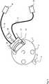
In
Die Fasern
Ferner ist auf dem Träger
In
Der Träger
Eine zweite beispielhafte Ausgestaltung einer erfindungsgemäßen Anordnung ist in
BezugszeichenlisteList of reference symbols
- 11
- Trägercarrier
- 22
- OptikmodulOptics module
- 33rd
- KoppelmodulCoupling module
- 44th
- FaserbündelFiber bundle
- 55
- FasernFibers
- 66th
- MesskopfMeasuring head
- 77th
- Linsenlenses
- 88th
- Heizkörperradiator
- 99
- Probenträger, ProbeSample carrier, sample
- 1010
- KreisbogenCircular arc
- 1111
- OptokopplerOptocoupler
- 1212th
- SchaltfahneSwitch flag
- 1313th
- DetektoreinheitDetector unit
- 1414th
- LichtquelleLight source
- 1515th
- FaserbündelFiber bundle
- 1616
- Motorengine
- 1717th
- FaserbündelFiber bundle
- 1818th
- Motorengine
ZITATE ENTHALTEN IN DER BESCHREIBUNGQUOTES INCLUDED IN THE DESCRIPTION
Diese Liste der vom Anmelder aufgeführten Dokumente wurde automatisiert erzeugt und ist ausschließlich zur besseren Information des Lesers aufgenommen. Die Liste ist nicht Bestandteil der deutschen Patent- bzw. Gebrauchsmusteranmeldung. Das DPMA übernimmt keinerlei Haftung für etwaige Fehler oder Auslassungen.This list of the documents listed by the applicant was generated automatically and is included solely for the better information of the reader. The list is not part of the German patent or utility model application. The DPMA assumes no liability for any errors or omissions.
Zitierte PatentliteraturPatent literature cited
- DE 102006036171 A1 [0006]DE 102006036171 A1 [0006]
Claims (13)
Translated fromGermanPriority Applications (5)
| Application Number | Priority Date | Filing Date | Title |
|---|---|---|---|
| DE102020106865.4ADE102020106865A1 (en) | 2020-03-12 | 2020-03-12 | Arrangement and method for PCR with multi-channel fluorescence measurement for spatially distributed samples |
| EP21159375.1AEP3879259B1 (en) | 2020-03-12 | 2021-02-25 | System and method for pcr with multi-channel fluorescence measurement for spatially distributed samples |
| CN202110255499.0ACN113388505B (en) | 2020-03-12 | 2021-03-09 | Apparatus and method for PCR using multi-channel fluorescence measurement of spatially distributed samples |
| US17/249,653US11994467B2 (en) | 2020-03-12 | 2021-03-09 | Arrangement and method for PCR with multi-channel fluorescence measurement for spatially distributed samples |
| US18/642,001US20240272076A1 (en) | 2020-03-12 | 2024-04-22 | Arrangement and method for pcr with multi-channel fluorescence measurement for spatially distributed samples |
Applications Claiming Priority (1)
| Application Number | Priority Date | Filing Date | Title |
|---|---|---|---|
| DE102020106865.4ADE102020106865A1 (en) | 2020-03-12 | 2020-03-12 | Arrangement and method for PCR with multi-channel fluorescence measurement for spatially distributed samples |
Publications (1)
| Publication Number | Publication Date |
|---|---|
| DE102020106865A1true DE102020106865A1 (en) | 2021-09-16 |
Family
ID=74758694
Family Applications (1)
| Application Number | Title | Priority Date | Filing Date |
|---|---|---|---|
| DE102020106865.4APendingDE102020106865A1 (en) | 2020-03-12 | 2020-03-12 | Arrangement and method for PCR with multi-channel fluorescence measurement for spatially distributed samples |
Country Status (4)
| Country | Link |
|---|---|
| US (2) | US11994467B2 (en) |
| EP (1) | EP3879259B1 (en) |
| CN (1) | CN113388505B (en) |
| DE (1) | DE102020106865A1 (en) |
Families Citing this family (4)
| Publication number | Priority date | Publication date | Assignee | Title |
|---|---|---|---|---|
| KR102572100B1 (en)* | 2020-11-12 | 2023-08-30 | 주식회사 엘티전자 | Optical fiber connecter and display apparatus with the same |
| CN113789261A (en)* | 2021-11-18 | 2021-12-14 | 深圳市刚竹智造科技有限公司 | Rotary wheel type optical assembly and rotary wheel type PCR optical system |
| DE102021133081B3 (en) | 2021-12-14 | 2023-05-04 | Bmg Labtech Gmbh | Microplate reader and method of making optical measurements with a microplate reader |
| DE102024201487A1 (en)* | 2024-02-19 | 2025-08-21 | Robert Bosch Gesellschaft mit beschränkter Haftung | Optical unit for fluorescence image display, in particular for an analysis device for detecting pathogens, and method for producing an optical unit |
Citations (12)
| Publication number | Priority date | Publication date | Assignee | Title |
|---|---|---|---|---|
| US5589351A (en) | 1994-12-06 | 1996-12-31 | Nps Pharmaceuticals, Inc. | Fluorescence detection apparatus |
| WO2001096837A1 (en) | 2000-06-15 | 2001-12-20 | Packard Instrument Company, Inc. | Universal microplate analyzer |
| WO2005068976A2 (en) | 2004-01-14 | 2005-07-28 | Applera Corporation | Apparatus and method for fluorescent detection in biological samples |
| WO2006052682A2 (en) | 2004-11-04 | 2006-05-18 | Applera Corporation | Optical scanning system comprising thermally compensated light emitting diode |
| DE102006036171A1 (en) | 2006-07-28 | 2008-01-31 | Analytik Jena Ag | Arrangement and method for rapid PCR with multichannel fluorescence measurement and method for their operation |
| DE102007030347A1 (en) | 2007-06-29 | 2009-01-02 | Ducrée, Jens, Dr. | Integrated rotor |
| WO2010022417A1 (en) | 2008-08-29 | 2010-03-04 | Anagnostics Bioanalysis Gmbh | Device for thermally regulating a rotationally symmetrical container |
| DE102009044795B3 (en) | 2009-12-07 | 2011-04-07 | Friz Biochem Gesellschaft Für Bioanalytik Mbh | Competition assay for the detection of nucleic acid oligomer hybridization events |
| WO2011054353A1 (en) | 2009-11-05 | 2011-05-12 | Friz Biochem Gesellschaft Für Bioanalytik Mbh | Device for performing pcr |
| US20120190034A1 (en) | 2009-08-06 | 2012-07-26 | Universal Bio Research Co., Ltd. | Optical fiber measurement device and measurement method using same |
| US20180037930A1 (en) | 2015-02-23 | 2018-02-08 | Hitachi High-Technologies Corporation | Nucleic Acid Analyzer |
| US10393659B2 (en) | 2011-05-16 | 2019-08-27 | Roche Molecular Systems, Inc. | Instrument and method for detecting analytes |
Family Cites Families (5)
| Publication number | Priority date | Publication date | Assignee | Title |
|---|---|---|---|---|
| US5449621A (en)* | 1989-07-31 | 1995-09-12 | Biotope, Inc. | Method for measuring specific binding assays |
| CN101156059B (en) | 2005-04-01 | 2011-06-08 | 3M创新有限公司 | Multiplex Fluorescence Detection Setup with Fiber Bundle Connecting Multiple Optical Modules to a Common Detector |
| US20070009382A1 (en)* | 2005-07-05 | 2007-01-11 | William Bedingham | Heating element for a rotating multiplex fluorescence detection device |
| EP2635896A1 (en)* | 2010-11-03 | 2013-09-11 | Reametrix Inc. | Method and device for fluorescent measurement of samples |
| CN106190806B (en)* | 2011-04-15 | 2018-11-06 | 贝克顿·迪金森公司 | Scan real-time microfluid thermal cycler and the method for synchronous thermal cycle and scanning optical detection |
- 2020
- 2020-03-12DEDE102020106865.4Apatent/DE102020106865A1/enactivePending
- 2021
- 2021-02-25EPEP21159375.1Apatent/EP3879259B1/enactiveActive
- 2021-03-09USUS17/249,653patent/US11994467B2/enactiveActive
- 2021-03-09CNCN202110255499.0Apatent/CN113388505B/enactiveActive
- 2024
- 2024-04-22USUS18/642,001patent/US20240272076A1/enactivePending
Patent Citations (13)
| Publication number | Priority date | Publication date | Assignee | Title |
|---|---|---|---|---|
| US5589351A (en) | 1994-12-06 | 1996-12-31 | Nps Pharmaceuticals, Inc. | Fluorescence detection apparatus |
| WO2001096837A1 (en) | 2000-06-15 | 2001-12-20 | Packard Instrument Company, Inc. | Universal microplate analyzer |
| WO2005068976A2 (en) | 2004-01-14 | 2005-07-28 | Applera Corporation | Apparatus and method for fluorescent detection in biological samples |
| WO2006052682A2 (en) | 2004-11-04 | 2006-05-18 | Applera Corporation | Optical scanning system comprising thermally compensated light emitting diode |
| DE102006036171A1 (en) | 2006-07-28 | 2008-01-31 | Analytik Jena Ag | Arrangement and method for rapid PCR with multichannel fluorescence measurement and method for their operation |
| DE102006036171B4 (en) | 2006-07-28 | 2008-10-09 | Analytik Jena Ag | Arrangement and method for multichannel fluorescence measurement in PCR samples |
| DE102007030347A1 (en) | 2007-06-29 | 2009-01-02 | Ducrée, Jens, Dr. | Integrated rotor |
| WO2010022417A1 (en) | 2008-08-29 | 2010-03-04 | Anagnostics Bioanalysis Gmbh | Device for thermally regulating a rotationally symmetrical container |
| US20120190034A1 (en) | 2009-08-06 | 2012-07-26 | Universal Bio Research Co., Ltd. | Optical fiber measurement device and measurement method using same |
| WO2011054353A1 (en) | 2009-11-05 | 2011-05-12 | Friz Biochem Gesellschaft Für Bioanalytik Mbh | Device for performing pcr |
| DE102009044795B3 (en) | 2009-12-07 | 2011-04-07 | Friz Biochem Gesellschaft Für Bioanalytik Mbh | Competition assay for the detection of nucleic acid oligomer hybridization events |
| US10393659B2 (en) | 2011-05-16 | 2019-08-27 | Roche Molecular Systems, Inc. | Instrument and method for detecting analytes |
| US20180037930A1 (en) | 2015-02-23 | 2018-02-08 | Hitachi High-Technologies Corporation | Nucleic Acid Analyzer |
Also Published As
| Publication number | Publication date |
|---|---|
| US11994467B2 (en) | 2024-05-28 |
| US20240272076A1 (en) | 2024-08-15 |
| US20210285878A1 (en) | 2021-09-16 |
| CN113388505A (en) | 2021-09-14 |
| CN113388505B (en) | 2025-03-04 |
| EP3879259A1 (en) | 2021-09-15 |
| EP3879259B1 (en) | 2023-11-15 |
Similar Documents
| Publication | Publication Date | Title |
|---|---|---|
| EP3879259B1 (en) | System and method for pcr with multi-channel fluorescence measurement for spatially distributed samples | |
| DE102006036171B4 (en) | Arrangement and method for multichannel fluorescence measurement in PCR samples | |
| DE102012204128B4 (en) | High-resolution scanning microscopy | |
| EP2592413B1 (en) | Method for measuring the fluorescence lifetime of an excited state in a sample | |
| DE202010018011U1 (en) | Optical system for chemical and / or biochemical reactions | |
| DE10131687A1 (en) | Device for carrying out nucleic acid amplification reactions while simultaneously monitoring the formation of amplification products | |
| DE102017122718A1 (en) | Method and apparatus for optically examining a plurality of microscopic samples | |
| WO2001027591A2 (en) | Method and device for characterizing a culture liquid | |
| EP2259125A3 (en) | Laser scanner device for fluorescence measurements | |
| DE4438391A1 (en) | Method and device for determining substance-specific parameters of one or fewer molecules by means of correlation spectroscopy | |
| DE102010045856A1 (en) | Optical imaging system for multispectral imaging | |
| DE112015006100T5 (en) | MORE COLORS DETECTION DEVICE | |
| WO2014041089A1 (en) | Device having an arrangement of optical elements | |
| EP3458844B1 (en) | Method and device for recording process parameters of fluid cultures | |
| CN105247345A (en) | Spectral microscopy device | |
| DE60020702T2 (en) | FIGURE ASSAY ANALYSIS FOR MICROPROBES | |
| DE60205406T2 (en) | OPTICAL TWO-WAVELENGTH FLUORESCENT ANALYZER | |
| DE60117703T2 (en) | EMITTING DEVICE PICTURE | |
| DE10054426B4 (en) | Method for multi-fluorescence detection | |
| DE102012219136A1 (en) | Microscope and a method for examining a sample with a microscope | |
| EP3660474B1 (en) | Apparatus and method for raman spectroscopy | |
| DE102007062250A1 (en) | Chemical and biological samples e.g. cell, testing device, has set of detecting devices arranged on base element, where each detecting device is attached to individual or group of sample receiving areas | |
| EP2375273A1 (en) | Fluorescence microscope and method for multiple positioning in a screening application | |
| EP4078144B1 (en) | Laboratory system | |
| DE10325735B4 (en) | Apparatus and method for analyzing a material library |
Legal Events
| Date | Code | Title | Description |
|---|---|---|---|
| R163 | Identified publications notified | ||
| R081 | Change of applicant/patentee | Owner name:ANALYTIK JENA GMBH+CO. KG, DE Free format text:FORMER OWNER: ANALYTIK JENA AG, 07745 JENA, DE | |
| R082 | Change of representative | Representative=s name:KOSLOWSKI, CHRISTINE, DR., DE Representative=s name:KOSLOWSKI, CHRISTINE, DIPL.-CHEM. DR. RER. NAT, DE | |
| R081 | Change of applicant/patentee | Owner name:ANALYTIK JENA GMBH+CO. KG, DE Free format text:FORMER OWNER: ANALYTIK JENA GMBH, 07745 JENA, DE |