DE102020102694A1 - Camera for a motor vehicle with a housing and a separate, electrically conductive printed circuit board carrier, and method - Google Patents
Camera for a motor vehicle with a housing and a separate, electrically conductive printed circuit board carrier, and methodDownload PDFInfo
- Publication number
- DE102020102694A1 DE102020102694A1DE102020102694.3ADE102020102694ADE102020102694A1DE 102020102694 A1DE102020102694 A1DE 102020102694A1DE 102020102694 ADE102020102694 ADE 102020102694ADE 102020102694 A1DE102020102694 A1DE 102020102694A1
- Authority
- DE
- Germany
- Prior art keywords
- circuit board
- housing
- camera
- board carrier
- lens device
- Prior art date
- Legal status (The legal status is an assumption and is not a legal conclusion. Google has not performed a legal analysis and makes no representation as to the accuracy of the status listed.)
- Pending
Links
Images


Classifications
- H—ELECTRICITY
- H04—ELECTRIC COMMUNICATION TECHNIQUE
- H04N—PICTORIAL COMMUNICATION, e.g. TELEVISION
- H04N23/00—Cameras or camera modules comprising electronic image sensors; Control thereof
- H04N23/50—Constructional details
- H04N23/51—Housings
- B—PERFORMING OPERATIONS; TRANSPORTING
- B60—VEHICLES IN GENERAL
- B60R—VEHICLES, VEHICLE FITTINGS, OR VEHICLE PARTS, NOT OTHERWISE PROVIDED FOR
- B60R11/00—Arrangements for holding or mounting articles, not otherwise provided for
- B60R11/04—Mounting of cameras operative during drive; Arrangement of controls thereof relative to the vehicle
- G—PHYSICS
- G02—OPTICS
- G02B—OPTICAL ELEMENTS, SYSTEMS OR APPARATUS
- G02B7/00—Mountings, adjusting means, or light-tight connections, for optical elements
- G02B7/02—Mountings, adjusting means, or light-tight connections, for optical elements for lenses
- H—ELECTRICITY
- H04—ELECTRIC COMMUNICATION TECHNIQUE
- H04N—PICTORIAL COMMUNICATION, e.g. TELEVISION
- H04N23/00—Cameras or camera modules comprising electronic image sensors; Control thereof
- H04N23/57—Mechanical or electrical details of cameras or camera modules specially adapted for being embedded in other devices
- H—ELECTRICITY
- H04—ELECTRIC COMMUNICATION TECHNIQUE
- H04N—PICTORIAL COMMUNICATION, e.g. TELEVISION
- H04N23/00—Cameras or camera modules comprising electronic image sensors; Control thereof
- H04N23/50—Constructional details
- H04N23/55—Optical parts specially adapted for electronic image sensors; Mounting thereof
- H—ELECTRICITY
- H05—ELECTRIC TECHNIQUES NOT OTHERWISE PROVIDED FOR
- H05K—PRINTED CIRCUITS; CASINGS OR CONSTRUCTIONAL DETAILS OF ELECTRIC APPARATUS; MANUFACTURE OF ASSEMBLAGES OF ELECTRICAL COMPONENTS
- H05K1/00—Printed circuits
- H05K1/02—Details
- H05K1/0213—Electrical arrangements not otherwise provided for
- H05K1/0215—Grounding of printed circuits by connection to external grounding means
Landscapes
- Engineering & Computer Science (AREA)
- Multimedia (AREA)
- Signal Processing (AREA)
- Physics & Mathematics (AREA)
- General Physics & Mathematics (AREA)
- Optics & Photonics (AREA)
- Mechanical Engineering (AREA)
- Camera Bodies And Camera Details Or Accessories (AREA)
- Studio Devices (AREA)
- Microelectronics & Electronic Packaging (AREA)
Abstract
Translated fromGermanDescription
Translated fromGermanEin Aspekt der Erfindung betrifft eine Kamera für ein Kraftfahrzeug. Die Kamera weist ein Gehäuse auf. Das Gehäuse ist aus einem elektrisch leitfähigen Material ausgebildet. Die Kamera weist darüber hinaus zumindest eine Leiterplatte auf, die in dem Gehäuse angeordnet ist. Ein weiterer Aspekt der Erfindung betrifft ein Verfahren zum Montieren einer Kamera.One aspect of the invention relates to a camera for a motor vehicle. The camera has a housing. The housing is made of an electrically conductive material. The camera also has at least one circuit board which is arranged in the housing. Another aspect of the invention relates to a method for mounting a camera.
Derartige Ausgestaltungen von Kameras sind aus dem Stand der Technik bekannt. So zeigt beispielsweise die
Darüber hinaus sind Ausgestaltungen bekannt, bei welchen eine Leiterplatte direkt an dem Gehäuseteil des Gehäuses der Kamera durch eine Lötverbindung befestigt ist. Da das Gehäuse der Kamera üblicherweise aus Metall, insbesondere Aluminium, ist, sind derartige Schweißverbindungen aufwendig und schwierig herzustellen. Das direkte Verlöten einer Leiterplatte an einer Innenseite eines Gehäuseteils des Gehäuses der Kamera weist daher auch Nachteile auf.In addition, embodiments are known in which a printed circuit board is attached directly to the housing part of the housing of the camera by means of a soldered connection. Since the housing of the camera is usually made of metal, in particular aluminum, such welded connections are complex and difficult to produce. Soldering a printed circuit board directly to an inside of a housing part of the housing of the camera therefore also has disadvantages.
Die Leiterplatte elektrisch mit dem üblicherweise metallischen Gehäuse zu verbinden, ist jedoch vorgesehen, um dieses Gehäuse auf Massepotential zu bringen.However, it is provided to electrically connect the circuit board to the usually metallic housing in order to bring this housing to ground potential.
Es ist Aufgabe der Erfindung, eine Kamera und ein Verfahren zu schaffen, bei welcher die elektrische Kontaktierung der Leiterplatte mit dem Gehäuse der Kamera verbessert ist.It is the object of the invention to create a camera and a method in which the electrical contact between the circuit board and the housing of the camera is improved.
Diese Aufgabe wird durch eine Kamera und ein Verfahren gemäß den unabhängigen Ansprüchen gelöst.This object is achieved by a camera and a method according to the independent claims.
Ein Aspekt der Erfindung betrifft eine Kamera für ein Kraftfahrzeug. Die Kamera weist ein Gehäuse auf. Das Gehäuse ist aus einem elektrisch leitfähigen Material ausgebildet. Darüber hinaus weist die Kamera zumindest eine Leiterplatte auf, die in dem Gehäuse angeordnet ist. Die Kamera weist einen zum Gehäuse separaten, elektrisch leitfähigen Leiterplattenträger auf. Dieser Leiterplattenträger trägt die Leiterplatte und ist elektrisch mit dieser Leiterplatte verbunden. Der Leiterplattenträger ist in dem Gehäuse angeordnet und mit dem Gehäuse elektrisch leitend verbunden. Durch eine derartige Ausgestaltung wird es ermöglicht, dass die Leiterplatte nicht mehr direkt mit dem Gehäuse der Kamera verbunden ist. Vielmehr ist dazu der separate Leiterplattenträger vorgesehen. Dieser ist somit ein Zusatzteil, an welchem die Leiterplatte direkt befestigt ist. Die Leiterplatte ist daher nicht mehr direkt an dem Gehäuse befestigt. Indem andererseits der Leiterplattenträger wiederum mit dem Gehäuse elektrisch leitend verbunden ist, ist somit zwischen der Leiterplatte und dem Gehäuse eine elektrische Verbindung indirekt ausgebildet. Dadurch ist es ermöglicht, dass das Gehäuse auf einfache Art und Weise und dennoch sicher mit Massepotential verbunden werden kann.One aspect of the invention relates to a camera for a motor vehicle. The camera has a housing. The housing is made of an electrically conductive material. In addition, the camera has at least one circuit board which is arranged in the housing. The camera has an electrically conductive printed circuit board carrier that is separate from the housing. This circuit board carrier carries the circuit board and is electrically connected to this circuit board. The circuit board carrier is arranged in the housing and connected to the housing in an electrically conductive manner. Such a configuration makes it possible that the circuit board is no longer directly connected to the housing of the camera. Rather, the separate circuit board carrier is provided for this purpose. This is therefore an additional part to which the circuit board is attached directly. The circuit board is therefore no longer attached directly to the housing. Since, on the other hand, the circuit board carrier is in turn electrically conductively connected to the housing, an electrical connection is thus indirectly formed between the circuit board and the housing. This makes it possible for the housing to be connected to ground potential in a simple and yet secure manner.
Der Leiterplattenträger ist insbesondere ein in sich formstabiler Formkörper. Dies bedeutet, dass er für sich betrachtet entsprechend steif ist. Er ist somit nicht nur eine bloße Folieneinlage ohne Beschichtung oder dergleichen. Er kann auch separat in das Gehäuse eingesetzt werden. Er kann auch aus dem Gehäuse entnommen werden. Der Leiterplattenträger ist dabei jeweils zerstörungsfrei lösbar einsetzbar oder entnehmbar.The circuit board carrier is, in particular, a molded body which is inherently dimensionally stable. This means that, viewed in isolation, it is correspondingly stiff. It is therefore not just a mere foil insert without a coating or the like. It can also be inserted separately into the housing. It can also be removed from the housing. The circuit board carrier can be inserted or removed in each case in a non-destructive manner.
Insbesondere weist die Kamera eine Schraub- und Klemmeinheit auf. Diese ist separat zum Gehäuse ausgebildet. Insbesondere ist der Leiterplattenträger Bestandteil dieser Schraub- und Klemmeinheit. Mit dieser Schraub- und Klemmeinheit ist es ermöglicht, dass eine Linseneinrichtung der Kamera direkt daran befestigt ist, insbesondere daran angeschraubt ist. Darüber hinaus ist diese Schraub- und Klemmeinheit in einer Richtung senkrecht zu einer Längsachse der Kamera an Innenseiten des Gehäuses mechanisch geklemmt. Dadurch hält sie ihre Position relativ zum Gehäuse in diesem Gehäuse.In particular, the camera has a screw and clamping unit. This is designed separately from the housing. In particular, the circuit board carrier is part of this screw and clamping unit. This screw and clamping unit makes it possible for a lens device of the camera to be attached directly to it, in particular to be screwed onto it. In addition, this screw and clamping unit is mechanically clamped on the inside of the housing in a direction perpendicular to a longitudinal axis of the camera. As a result, it holds its position relative to the housing in this housing.
In einer vorteilhaften Ausführung ist vorgesehen, dass der Leiterplattenträger zumindest ein Klemmelement aufweist. Mit diesem Klemmelement ist der Leiterplattenträger an einer Innenseite des Gehäuses verklemmt. Insbesondere ist dieses Klemmelement einstückig mit dem Leiterplattenträger ausgebildet. In einer Richtung senkrecht zur Längsachse der Kamera ist dieses Klemmelement seitlich von einem Rand des Leiterplattenträgers abstehend angeordnet. Insbesondere ist der Leiterplattenträger mit diesem Klemmelement direkt an einer Innenseite des Gehäuses verklemmt angeordnet.In an advantageous embodiment it is provided that the circuit board carrier has at least one clamping element. The circuit board carrier is clamped to an inside of the housing with this clamping element. In particular, this clamping element is designed in one piece with the circuit board carrier. In a direction perpendicular to the longitudinal axis of the camera, this clamping element is arranged protruding laterally from an edge of the circuit board carrier. In particular, the circuit board carrier is arranged clamped with this clamping element directly on an inside of the housing.
Dadurch ist es ermöglicht, dass dieser Leiterplattenträger insbesondere ohne Lötverbindung mit dem Gehäuse direkt mit dem Gehäuse mechanisch verbunden werden kann. Dies ist ein weiterer Vorteil. Denn das Gehäuse ist insbesondere zumindest bereichsweise aus einem Metall, insbesondere Aluminium, ausgebildet. Aluminium ist ein besonders vorteilhaftes Material für dieses Gehäuse. Einerseits ist es leicht. Andererseits ist es besonders robust gegenüber Umwelteinflüssen, denen die Kamera am Kraftfahrzeug ausgesetzt ist. Da, wie eingangs erwähnt, Lötverbindungen mit Aluminium schwierig sind und aufwendig herzustellen sind, ist diese Klemmverbindung besonders vorteilhaft. Insbesondere ist der Leiterplattenträger nur durch eine derartige Klemmverbindung zwischen dem Klemmelement und dem Gehäuse positionsstabil in dem Gehäuse gehalten. Insbesondere ist dieses Klemmelement Bestandteil der vorteilhaft ausgebildeten Schraub- und Klemmeinheit der Kamera.This makes it possible for this printed circuit board carrier to be mechanically connected directly to the housing, in particular without a soldered connection to the housing. This is another benefit. Because the case is particular at least formed in some areas from a metal, in particular aluminum. Aluminum is a particularly advantageous material for this housing. On the one hand, it's easy. On the other hand, it is particularly robust against environmental influences to which the camera on the motor vehicle is exposed. Since, as mentioned at the beginning, soldered connections with aluminum are difficult and expensive to produce, this clamp connection is particularly advantageous. In particular, the circuit board carrier is held in a stable position in the housing only by such a clamping connection between the clamping element and the housing. In particular, this clamping element is part of the advantageously designed screw and clamping unit of the camera.
In einer vorteilhaften Ausführung ist vorgesehen, dass der Leiterplattenträger zumindest zwei separate Klemmelemente aufweist. Diese sind an unterschiedlichen Randabschnitten des Rands des Leiterplattenträgers ausgebildet. Insbesondere sind sie an gegenüberliegenden Randabschnitten ausgebildet. Dadurch kann ein besonders stabiles Verklemmen des Leiterplattenträgers an gegenüberliegenden Innenseiten von gegenüberliegenden Seitenwänden des Gehäuses erfolgen. Ein besonders vorteilhafter geklemmter Zustand des Leiterplattenträgers an dem Gehäuse ist dadurch erreicht.In an advantageous embodiment it is provided that the circuit board carrier has at least two separate clamping elements. These are formed on different edge sections of the edge of the circuit board carrier. In particular, they are formed on opposite edge sections. As a result, the printed circuit board carrier can be clamped in a particularly stable manner on opposite inner sides of opposite side walls of the housing. A particularly advantageous clamped state of the circuit board carrier on the housing is achieved.
Es können auch mehr als zwei separate Klemmelemente ausgebildet sein. Insbesondere sind diese jeweils an verschiedenen Randabschnitten des Rands des Leiterplattenträgers ausgebildet. Die Klemmelemente können als Klemmlaschen ausgebildet sein. Sie stehen dann diesbezüglich insbesondere flügelartig von dem Rand ab.More than two separate clamping elements can also be formed. In particular, these are each formed on different edge sections of the edge of the circuit board carrier. The clamping elements can be designed as clamping lugs. In this regard, they then protrude from the edge in a particularly wing-like manner.
In einer vorteilhaften Ausführung ist vorgesehen, dass der Leiterplattenträger plattenartig ausgebildet ist. Er weist vorzugsweise ein Loch auf. Dieses Loch ist umlaufend vollständig begrenzt. Es ist somit kein randseitig offenes Loch. In dieses Loch erstreckt sich eine dazu separate Linseneinrichtung der Kamera. Insbesondere ist somit die Linseneinrichtung in Richtung der Längsachse der Kamera betrachtet überlappend mit diesem Leiterplattenträger, insbesondere dem Loch, ausgebildet.In an advantageous embodiment it is provided that the circuit board carrier is designed in the manner of a plate. It preferably has a hole. This hole is completely delimited all around. It is therefore not a hole with an open edge. A separate lens device of the camera extends into this hole. In particular, the lens device, viewed in the direction of the longitudinal axis of the camera, is designed to overlap with this circuit board carrier, in particular the hole.
In einer vorteilhaften Ausführung ist vorgesehen, dass die Fläche des Leiterplattenträgers, die durch einen Rand beziehungsweise eine Randkontur dieses Leiterplattenträgers begrenzt ist, zumindest 80 Prozent, insbesondere zumindest 90 Prozent, insbesondere zumindest 95 Prozent der Fläche, die durch Innenseiten von Seitenwänden des Gehäuses begrenzt ist, beträgt. Diese jeweiligen Flächen sind in einer Ebene senkrecht zur Längsachse der Kamera betrachtet zu verstehen. Dies bedeutet, dass der Leiterplattenträger eine Größe aufweist, die diese Fläche zwischen den Innenseiten des Gehäuses nahezu vollständig aufweist. Insbesondere ist der Leiterplattenträger mit einer Fläche ausgebildet, die kleiner 99 Prozent, insbesondere kleiner 98 Prozent dieser Fläche zwischen den Innenseiten des Gehäuses beträgt. Durch eine derartige Ausgestaltung ist es ermöglicht, dass einerseits ein stabiler Leiterplattenträger ausgebildet werden kann und andererseits ein Klemmelement in Richtung senkrecht zur Längsachse der Kamera betrachtet relativ klein ausgebildet werden kann. Dadurch kann die Klemmwirkung besonders vorteilhaft erreicht werden. Denn damit ist auch ein Klemmelement in gewissem Maße geringfügig flexibel und verformbar. Andererseits weist es keine diesbezügliche Länge auf, die eine unerwünscht hohe Flexibilität des Klemmelements nach sich ziehen würde. Ein unerwünschtes starkes Verbiegen und gegebenenfalls ein Abbrechen des Klemmelements ist dadurch vermieden.In an advantageous embodiment it is provided that the area of the circuit board carrier, which is limited by an edge or an edge contour of this circuit board carrier, is at least 80 percent, in particular at least 90 percent, in particular at least 95 percent of the area that is limited by the inside of side walls of the housing , amounts to. These respective surfaces are to be understood as viewed in a plane perpendicular to the longitudinal axis of the camera. This means that the printed circuit board carrier has a size that almost completely has this area between the inner sides of the housing. In particular, the circuit board carrier is designed with an area that is less than 99 percent, in particular less than 98 percent of this area between the inner sides of the housing. Such a configuration makes it possible, on the one hand, to design a stable circuit board carrier and, on the other hand, to design a clamping element that is relatively small when viewed in the direction perpendicular to the longitudinal axis of the camera. As a result, the clamping effect can be achieved particularly advantageously. This is because a clamping element is thus also slightly flexible and deformable to a certain extent. On the other hand, it does not have a length in this respect that would result in an undesirably high flexibility of the clamping element. This avoids excessive bending and possibly breaking off of the clamping element.
In einer vorteilhaften Ausführung ist vorgesehen, dass die Linseneinrichtung in dem Loch des Leiterplattenträgers befestigt ist. Es kann in dem Zusammenhang eine haltende mechanische Verbindung vorgesehen sein. Dies kann beispielsweise eine Gewindeverbindung sein. Bei einer derartigen Ausgestaltung ist somit die Linseneinrichtung durch eine Schraubverbindung in dem Loch gehalten. Insbesondere ist die Linseneinrichtung nur in diesem Loch verschraubt angeordnet. Durch eine derartige Ausgestaltung ist es ermöglicht, dass die Linseneinrichtung nicht mehr direkt an dem Gehäuse, insbesondere einem Gehäusevorderteil, verschraubt werden muss. Ein Ausbilden eines Innengewindes in diesem Gehäusevorderteil ist daher nicht mehr erforderlich. Einerseits ist es dadurch ermöglicht, das Gehäuse fertigungstechnisch einfacher zu gestalten. Andererseits ist es dadurch ermöglicht, die Linseneinrichtung durch die Verschraubung in dem Loch des Leiterplattenträgers sehr stabil und somit positionsfixiert anzuordnen.In an advantageous embodiment it is provided that the lens device is fastened in the hole of the circuit board carrier. A holding mechanical connection can be provided in this context. This can be a threaded connection, for example. In such a configuration, the lens device is thus held in the hole by a screw connection. In particular, the lens device is arranged screwed only in this hole. Such a configuration makes it possible that the lens device no longer has to be screwed directly to the housing, in particular a front part of the housing. It is therefore no longer necessary to form an internal thread in this front part of the housing. On the one hand, this makes it possible to make the housing simpler in terms of production technology. On the other hand, this makes it possible to arrange the lens device in a very stable and thus fixed position through the screw connection in the hole of the circuit board carrier.
Es kann vorgesehen sein, dass diese Schraubverbindung ein Gewinde aufweist, welches ein Innengewinde ist. Dieses Innengewinde kann in einer vorteilhaften Ausführung direkt an dem Leiterplattenträger ausgebildet sein. Es kann in dem Zusammenhang beispielsweise an einer Begrenzungswand, die das Loch begrenzt, ausgebildet sein. Bei dieser Ausgestaltung ist die Linseneinrichtung dann direkt an dem Leiterplattenträger versch rau bt.It can be provided that this screw connection has a thread which is an internal thread. In an advantageous embodiment, this internal thread can be formed directly on the circuit board carrier. In this context, it can be formed, for example, on a delimitation wall which delimits the hole. In this embodiment, the lens device is then screwed directly onto the circuit board carrier.
Insbesondere ist in dem Loch ein Innengewinde ausgebildet. Dieses ist mit einem Außengewinde, welches an der Linseneinrichtung ausgebildet ist, verschraubt.In particular, an internal thread is formed in the hole. This is screwed to an external thread which is formed on the lens device.
In einer vorteilhaften Ausführung ist vorgesehen, dass zwischen dem Innengewinde und dem Außengewinde ein Klebstoff eingebracht ist. Durch eine derartige Ausgestaltung wird die Schraubverbindung im Hinblick auf ihre feste Verbindung und dauerhaft stabile Positionsfixierung nochmals verbessert ausgebildet. Insbesondere Vibrationen, wie sie im Betrieb des Kraftfahrzeugs auf die Kamera übertragen werden, führen dann im besonderen Maße nicht dazu, dass sich die Schraubverbindung lösen könnte.In an advantageous embodiment it is provided that an adhesive is introduced between the internal thread and the external thread. Such a configuration makes the screw connection With regard to their firm connection and permanently stable position fixation, they are further improved. In particular, vibrations, such as those transmitted to the camera when the motor vehicle is in operation, do not lead to any particular degree that the screw connection could loosen.
In einer vorteilhaften Ausführung ist vorgesehen, dass in dem Loch des Leiterplattenträgers ein zum Leiterplattenträger und zum Gehäuse separater Haltering angeordnet ist. Dieser Haltering ist ein besonders vorteilhaftes Bauteil. Es ermöglicht es, den separaten Leiterplattenträger, das dazu separate Gehäuseteil des Gehäuses und die wiederum dazu separate Linseneinrichtung zueinander zu halten. Der Haltering ist insbesondere dahingehend ausgebildet, dass er in seiner montierten Endposition im Gehäuse der Kamera die Linseneinrichtung direkt hält, andererseits den Leiterplattenträger senkrecht zur Längsachse der Kamera an die Innenseite der Seitenwände des Gehäuses andrückt. Insbesondere sodass dadurch der Leiterplattenträger an diesem Gehäuse verklemmt ist.In an advantageous embodiment it is provided that a retaining ring separate from the circuit board carrier and the housing is arranged in the hole of the circuit board carrier. This retaining ring is a particularly advantageous component. It makes it possible to hold the separate printed circuit board carrier, the separate housing part of the housing and, in turn, the separate lens device with respect to one another. The retaining ring is designed in such a way that it holds the lens device directly in its mounted end position in the housing of the camera, and on the other hand presses the circuit board carrier perpendicular to the longitudinal axis of the camera against the inside of the side walls of the housing. In particular so that the circuit board carrier is jammed on this housing.
In seiner montierten Endposition ist der Haltering in Richtung der Längsachse der Kamera zumindest bereichsweise überlappend mit dem Leiterplattenträger angeordnet. Er ist insbesondere zumindest bereichsweise in das Loch des Leiterplattenträgers hineinragend angeordnet. Darüber hinaus ist der Haltering in Richtung der Längsachse der Kamera betrachtet mit der Linseneinrichtung überlappend angeordnet.In its assembled end position, the retaining ring is arranged in the direction of the longitudinal axis of the camera so as to overlap with the printed circuit board carrier at least in some areas. In particular, it is arranged so as to protrude into the hole in the circuit board carrier, at least in some areas. In addition, the retaining ring, viewed in the direction of the longitudinal axis of the camera, is arranged so as to overlap with the lens device.
Der Haltering weist in einer vorteilhaften Ausführung eine Formgebung auf, durch welche beim Einbringen des Halterings in seine Endposition der Leiterplattenträger senkrecht zur Längsachse der Kamera nach außen gedrückt wird und zu Innenseiten von Längsseiten des Gehäuses hin gedrückt wird. Durch diese Ausgestaltung stellt sich dann die Klemmung des Leiterplattenträgers an diesen Innenseiten der Seitenwände der Kamera ein. In einer vorteilhaften Ausführung ist vorgesehen, dass eine Außenseite beziehungsweise eine Umfangswand dieses Halterings nicht vollständig parallel zur Längsachse der Kamera ausgebildet ist. Insbesondere ist dieser Haltering an seiner Umfangswand gestuft ausgebildet. Insbesondere weist diese Umfangswand einen Schrägabschnittverlauf (in einem Querschnitt des Halterings betrachtet) auf. Durch diese Wandschräge ist der Haltering an seiner Außenkontur zumindest bereichsweise konusförmig gebildet. Insbesondere ist vorgesehen, dass die Begrenzungswand, welche das Loch in dem Leiterplattenträger begrenzt, nicht vollständig vertikal ausgebildet ist und somit nicht vollständig parallel zur Längsachse der Kamera ausgebildet ist. Insbesondere ist diese Begrenzungswand in einem Querschnitt betrachtet mit einer Begrenzungswandschräge ausgebildet. Insbesondere ist die Begrenzungswand des Lochs somit bereichsweise trichterartig ausgebildet. Durch diese Begrenzungswandschräge und die Wandschräge wird somit eine Komplementärgeometrie geschaffen. Durch diese wird beim Einsetzen des Halterings in das Loch und bei einem Bewegen des Halterings in Richtung der Längsachse relativ zum Leiterplattenträger ein aneinander Anliegen dieser Wandschräge und der Begrenzungswandschräge erreicht. Bei einem weiteren axialen Bewegen des Halterings relativ zum Leiterplattenträger gleiten diese genannten Wandschrägen aneinander und der Leiterplattenträger wird senkrecht zur Längsachse nach außen gedrückt. Das zumindest eine Klemmelement wird dann an die Innenseite einer Seitenwand des Gehäuses angedrückt, sodass die Klemmwirkung aufgebaut wird.In an advantageous embodiment, the retaining ring has a shape which, when the retaining ring is brought into its end position, pushes the printed circuit board carrier outwards perpendicular to the longitudinal axis of the camera and pushes it towards the inside of the longitudinal sides of the housing. This configuration then results in the clamping of the circuit board carrier on these inner sides of the side walls of the camera. In an advantageous embodiment it is provided that an outside or a peripheral wall of this retaining ring is not designed completely parallel to the longitudinal axis of the camera. In particular, this retaining ring is stepped on its peripheral wall. In particular, this peripheral wall has an inclined section profile (viewed in a cross section of the retaining ring). Due to this wall slope, the retaining ring is at least partially conical on its outer contour. In particular, it is provided that the delimitation wall which delimits the hole in the circuit board carrier is not completely vertical and is therefore not completely parallel to the longitudinal axis of the camera. In particular, this boundary wall is designed with a boundary wall slope when viewed in a cross section. In particular, the delimiting wall of the hole is thus designed in a funnel-like manner in some areas. A complementary geometry is thus created by this boundary wall slope and the wall slope. As a result of this, when the retaining ring is inserted into the hole and when the retaining ring is moved in the direction of the longitudinal axis relative to the printed circuit board carrier, this wall slope and the boundary wall slope are in contact with one another. With a further axial movement of the retaining ring relative to the printed circuit board carrier, said wall bevels slide against one another and the printed circuit board carrier is pressed outwards perpendicular to the longitudinal axis. The at least one clamping element is then pressed against the inside of a side wall of the housing, so that the clamping effect is built up.
In einer vorteilhaften Ausführung ist vorgesehen, dass der Haltering an einer Oberseite, die der Linseneinrichtung abgewandt ist, eine Eingriffskontur aufweist. In diese Eingriffskontur kann beispielsweise ein Werkzeug eingreifen, um ein Drehmoment um die Längsachse der Kamera auf den Haltering aufbringen zu können.In an advantageous embodiment it is provided that the retaining ring has an engagement contour on an upper side which faces away from the lens device. A tool can, for example, engage in this engagement contour in order to be able to apply a torque about the longitudinal axis of the camera to the retaining ring.
Insbesondere ist vorgesehen, dass der Haltering an seiner Innenseite ein Innengewinde aufweist. In dieses Innengewinde kann ein Außengewinde, welches an der Linseneinrichtung ausgebildet ist, eingeschraubt werden. Die Linseneinrichtung kann somit bei diesem Ausführungsbeispiel direkt an dem Haltering verschraubt werden. Wird die Linseneinrichtung an diesem Haltering verschraubt, so bewegt sich die Linseneinrichtung in Richtung der Längsachse der Kamera zu dem Haltering hin. Dies erfolgt so lange, bis eine Anlagefläche einer Linseneinrichtung an einer Gegenanlagefläche eines Gehäuseflansches des Gehäuses, insbesondere eines Gehäusefrontteils des Gehäuses, anliegt. In diesem Zustand wird dann bei weiterem Eindrehen der Linseneinrichtung in den Haltering der Haltering in axialer Richtung in das Loch oder weiter in das Loch des Leiterplattenträgers hineingezogen. Dadurch erfolgt das Bewegen des Leiterplattenträgers senkrecht zur Längsachse und das oben bereits erläuterte Verklemmen des Klemmelements des Leiterplattenträgers an der Innenseite des Gehäuses, insbesondere eines Gehäusefrontteils des Gehäuses.In particular, it is provided that the retaining ring has an internal thread on its inside. An external thread, which is formed on the lens device, can be screwed into this internal thread. In this exemplary embodiment, the lens device can thus be screwed directly onto the retaining ring. If the lens device is screwed to this retaining ring, the lens device moves in the direction of the longitudinal axis of the camera towards the retaining ring. This takes place until a contact surface of a lens device is in contact with a counter-contact surface of a housing flange of the housing, in particular a housing front part of the housing. In this state, as the lens device is screwed further into the retaining ring, the retaining ring is drawn in the axial direction into the hole or further into the hole of the circuit board carrier. As a result, the circuit board carrier is moved perpendicular to the longitudinal axis and the clamping element of the circuit board carrier is clamped on the inside of the housing, in particular a front part of the housing, as explained above.
In einer vorteilhaften Ausführung ist vorgesehen, dass der Haltering ein integriertes Innengewinde aufweist. Das Innengewinde ist somit einstückig mit dem Haltering ausgebildet. Insbesondere ist der Haltering als einstückiges Bauteil ausgebildet. Das Innengewinde ist mit einem Außengewinde, welches an der Linseneinrichtung angeordnet ist, verschraubt.In an advantageous embodiment it is provided that the retaining ring has an integrated internal thread. The internal thread is thus formed in one piece with the retaining ring. In particular, the retaining ring is designed as a one-piece component. The internal thread is screwed to an external thread which is arranged on the lens device.
In einer vorteilhaften Ausführung ist der Haltering Bestandteil der oben erwähnten Schraub- und Klemmeinheit der Kamera.In an advantageous embodiment, the retaining ring is part of the above-mentioned screw and clamping unit of the camera.
Er kann in einer vorteilhaften Ausführung ein zum Leiterplattenträger separates Bauteil sein.In an advantageous embodiment, it can be a separate component from the circuit board carrier.
Es kann auch vorgesehen sein, dass der Leiterplattenträger und der Haltering einstückig ausgebildet sind. Insbesondere ist diese einstückige Ausgestaltung jedoch derart, dass der Haltering und der Leiterplattenträger relativ zueinander bewegbar sind. Insbesondere ist dies in Richtung einer Längsachse der Kamera zu sehen. Diese Längsachse der Kamera ist insbesondere auch die Lochachse des Lochs des Leiterplattenträgers. Insbesondere ist sie auch die Längsachse des Halterings. Beispielsweise kann vorgesehen sein, dass bei einer derartigen einstückigen Ausgestaltung des Leiterplattenträgers und des Halterings diese beiden Komponenten mit zumindest einem elastischen Element verbunden sind. Dies kann beispielsweise ein elastischer Bügel sein. Es kann jedoch auch eine elastische Feder sein. Beispielsweise kann dies eine Art Blattfeder sein. Insbesondere können mehrere derartige elastische Elemente vorgesehen sein.It can also be provided that the circuit board carrier and the retaining ring are formed in one piece. In particular, however, this one-piece configuration is such that the retaining ring and the circuit board carrier can be moved relative to one another. In particular, this can be seen in the direction of a longitudinal axis of the camera. This longitudinal axis of the camera is in particular also the hole axis of the hole in the circuit board carrier. In particular, it is also the longitudinal axis of the retaining ring. For example, it can be provided that with such a one-piece configuration of the circuit board carrier and the retaining ring, these two components are connected to at least one elastic element. This can be an elastic bracket, for example. However, it can also be an elastic spring. For example, this can be a type of leaf spring. In particular, several such elastic elements can be provided.
Insbesondere ist der Haltering aus einem elektrisch leitfähigen Material ausgebildet. Insbesondere ist bei einer einstückigen Ausgestaltung zwischen dem Haltering und dem Leiterplattenträger dieses gesamte einstückige Bauteil aus einem elektrisch leitfähigen Material ausgebildet.In particular, the retaining ring is made from an electrically conductive material. In particular, in the case of a one-piece configuration between the retaining ring and the circuit board carrier, this entire one-piece component is formed from an electrically conductive material.
In einer vorteilhaften Ausführung kann vorgesehen sein, dass der Haltering ein Klemmring ist, mit welchem der Leiterplattenträger an die Innenseite des Gehäuses senkrecht zur Längsachse der Kamera angedrückt ist.In an advantageous embodiment it can be provided that the retaining ring is a clamping ring with which the circuit board carrier is pressed onto the inside of the housing perpendicular to the longitudinal axis of the camera.
In einer vorteilhaften Ausführung ist vorgesehen, dass der Haltering eine gestufte Außenwand beziehungsweise Umfangswand aufweist. An dieser ist, wie bereits oben dargelegt, eine Wandschräge beziehungsweise eine Außenwandschräge ausgebildet. Eine das Loch in dem Leiterplattenträger begrenzende Begrenzungswand weist eine komplementär geneigte Wandschräge beziehungsweise Begrenzungswandschräge auf. Die Außenwandschräge liegt an dieser Wandschräge an.In an advantageous embodiment it is provided that the retaining ring has a stepped outer wall or peripheral wall. As already explained above, a wall slope or an outer wall slope is formed on this. A delimiting wall delimiting the hole in the printed circuit board carrier has a wall bevel or delimiting wall inclined in a complementary manner. The outer wall slope rests against this wall slope.
In einer vorteilhaften Ausführung ist vorgesehen, dass die Linseneinrichtung nur mit dem von dem Gehäuse separaten Innengewinde verschraubt ist. Insbesondere ist keine direkte Schraubverbindung zwischen dem Gehäuse und der Linseneinrichtung ausgebildet.In an advantageous embodiment it is provided that the lens device is only screwed to the internal thread which is separate from the housing. In particular, no direct screw connection is formed between the housing and the lens device.
Die Linseneinrichtung ist somit nur durch eine Öffnung beziehungsweise ein Loch in dem Gehäuse, insbesondere einem Gehäusefrontteil, hindurchgeführt und erstreckt sich beidseits dieses Lochs. Insbesondere liegt die Linseneinrichtung mit einem radialen Flansch an einer Anlagefläche beziehungsweise einer Stirnfläche, einer Begrenzungswand, die das Loch in dem Gehäuse begrenzt, an.The lens device is thus only passed through an opening or a hole in the housing, in particular a housing front part, and extends on both sides of this hole. In particular, the lens device rests with a radial flange on a contact surface or an end surface, a delimitation wall which delimits the hole in the housing.
Vorzugsweise ist vorgesehen, dass die Linseneinrichtung mit einer Anlagefläche an einer Gegenanlagefläche eines Gehäuseflansches des Gehäuses anliegt. Der Gehäuseflansch begrenzt ein Loch in dem Gehäuse. Durch dieses Loch erstreckt sich die Linseneinrichtung in das Innere des Gehäuses.It is preferably provided that the lens device rests with a contact surface on a counter contact surface of a housing flange of the housing. The housing flange defines a hole in the housing. The lens device extends through this hole into the interior of the housing.
In einer vorteilhaften Ausführung ist vorgesehen, dass die Anlagefläche in Richtung der Längsachse der Kamera betrachtet durch die Schraubverbindung an die Gegenanlagefläche angedrückt ist. Es ist somit ein axiales Andrücken dieser Anlagefläche an die Gegenanlagefläche durch diese Schraubverbindung erreicht.In an advantageous embodiment, it is provided that the contact surface, viewed in the direction of the longitudinal axis of the camera, is pressed against the counter contact surface by the screw connection. Axial pressing of this contact surface against the counter contact surface is thus achieved by this screw connection.
Vorzugsweise ist vorgesehen, dass der Leiterplattenträger zumindest zwei Kontaktstifte aufweist. Diese Kontaktstifte sind einstückig am Leiterplattenträger ausgebildet. Diese Kontaktstifte sind mit der Leiterplatte fest verbunden. Insbesondere ist hier eine elektrisch leitende Verbindung zwischen den Kontaktstiften und der Leiterplatte ausgebildet. Insbesondere ist vorgesehen, dass die Kontaktstifte jeweils mit einer Lötverbindung mit der Leiterplatte verbunden sind.It is preferably provided that the circuit board carrier has at least two contact pins. These contact pins are formed in one piece on the circuit board carrier. These contact pins are firmly connected to the circuit board. In particular, an electrically conductive connection is formed here between the contact pins and the circuit board. In particular, it is provided that the contact pins are each connected to the circuit board with a soldered connection.
In einer vorteilhaften Ausführung ist vorgesehen, dass der Leiterplattenträger zumindest einen Versteifungssteg aufweist. Dadurch ist dieser Leiterplattenträger besonders steif ausgebildet. Eine unerwünschte Verwindung ist dadurch vermieden. Insbesondere ist der Versteifungssteg als umlaufend geschlossener Versteifungssteg ausgebildet.In an advantageous embodiment it is provided that the circuit board carrier has at least one stiffening web. As a result, this circuit board carrier is designed to be particularly rigid. This avoids unwanted twisting. In particular, the stiffening web is designed as a circumferentially closed stiffening web.
Es kann darüber hinaus auch vorgesehen sein, dass die Kamera eine Staubschutzblende aufweist. Diese ist vorzugsweise im Gehäuse angeordnet. Dadurch wird vermieden, dass Staub in einen optischen Pfad zwischen der Linseneinrichtung und dem Bildsensor, der auf der Leiterplatte angeordnet ist, gelangen kann. Dieses Staubschutzelement ist vorzugsweise an dem Haltering angeordnet. Es ist insbesondere ebenfalls ringförmig ausgebildet und um die Längsachse der Kamera umlaufend geschlossen ausgebildet. In axialer Richtung ist dadurch derjenige Freiraum zwischen dem Bildsensor und der Linseneinrichtung um die Längsachse umlaufend abgedeckt. Insbesondere ist dieses Staubschutzelement in axialer Richtung elastisch ausgebildet.It can also be provided that the camera has a dust cover. This is preferably arranged in the housing. This prevents dust from getting into an optical path between the lens device and the image sensor which is arranged on the circuit board. This dust protection element is preferably arranged on the retaining ring. In particular, it is also designed in the form of a ring and is designed to be closed circumferentially around the longitudinal axis of the camera. In the axial direction that free space between the image sensor and the lens device is thereby covered circumferentially around the longitudinal axis. In particular, this dust protection element is designed to be elastic in the axial direction.
In einem weiteren unabhängigen Aspekt der Erfindung weist eine Kamera für ein Kraftfahrzeug ein Gehäuse auf. Dieses Gehäuse ist zumindest bereichsweise aus einem elektrisch leitfähigen Material ausgebildet. Die Kamera weist darüber hinaus zumindest eine Leiterplatte auf. Diese Leiterplatte ist in dem Gehäuse angeordnet. Die Kamera weist einen zum Gehäuse separaten Haltering auf. Dieser Haltering ist auch zur Leiterplatte separat ausgebildet. Der Haltering ist in dem Gehäuse angeordnet. Die Kamera weist darüber hinaus eine Linseneinrichtung auf. Diese erstreckt sich durch ein Loch in dem Gehäuse in das Innere des Gehäuses. Die Linseneinrichtung weist ein Außengewinde auf. Dieses ist mit einem Innengewinde, das in dem Haltering ausgebildet ist, verschraubt. Insbesondere ist nur eine Schraubverbindung zwischen dem Haltering und der Linseneinrichtung ausgebildet. Die Linseneinrichtung ist somit nur direkt an dem Haltering verschraubt.In a further independent aspect of the invention, a camera for a motor vehicle a housing on. This housing is made of an electrically conductive material at least in some areas. The camera also has at least one circuit board. This circuit board is arranged in the housing. The camera has a retaining ring that is separate from the housing. This retaining ring is also formed separately from the circuit board. The retaining ring is arranged in the housing. The camera also has a lens device. This extends through a hole in the housing into the interior of the housing. The lens device has an external thread. This is screwed to an internal thread which is formed in the retaining ring. In particular, only one screw connection is formed between the retaining ring and the lens device. The lens device is therefore only screwed directly to the retaining ring.
Ein weiterer unabhängiger Aspekt der Erfindung betrifft eine Kamera für ein Kraftfahrzeug. Die Kamera weist ein Gehäuse auf. Das Gehäuse ist zumindest bereichsweise aus einem elektrisch leitfähigen Material ausgebildet. Darüber hinaus weist die Kamera zumindest eine Leiterplatte auf. Die Leiterplatte ist in dem Gehäuse angeordnet. Die Kamera weist eine zum Gehäuse separate Schraub-Klemmeinheit auf. An dieser Schraub-Klemmeinheit ist eine Linseneinrichtung mit der Kamera direkt verschraubt. Darüber hinaus ist die Schraub-Klemmeinheit in Richtung senkrecht zu einer Längsachse der Kamera an einer Innenseite des Gehäuses geklemmt angeordnet.Another independent aspect of the invention relates to a camera for a motor vehicle. The camera has a housing. The housing is made of an electrically conductive material at least in some areas. In addition, the camera has at least one circuit board. The circuit board is arranged in the housing. The camera has a screw clamping unit separate from the housing. A lens device is screwed directly to the camera on this screw-clamping unit. In addition, the screw-clamping unit is arranged clamped on an inside of the housing in the direction perpendicular to a longitudinal axis of the camera.
Ausführungen des ersten unabhängigen Aspekts betreffend die Kamera sind als vorteilhafte Ausführungen der oben genannten weiteren unabhängigen Aspekte anzusehen.Statements of the first independent aspect relating to the camera are to be regarded as advantageous implementations of the further independent aspects mentioned above.
Ein weiterer Aspekt der Erfindung betrifft ein Verfahren zum Montieren einer Kamera, mit einem Gehäuse, welches aus einem elektrisch leitfähigen Material ausgebildet ist, mit zumindest einer Leiterplatte, die in dem Gehäuse angeordnet wird. Die Leiterplatte wird mit einem zum Gehäuse separaten, elektrisch leitfähigen Leiterplattenträger der Kamera getragen. Der Leiterplattenträger wird elektrisch leitend mit der Leiterplatte verbunden, wobei der Leiterplattenträger in dem Gehäuse angeordnet wird und mit dem Gehäuse elektrisch leitend verbunden wird.Another aspect of the invention relates to a method for mounting a camera, having a housing which is formed from an electrically conductive material, with at least one circuit board which is arranged in the housing. The circuit board is carried by an electrically conductive circuit board carrier of the camera that is separate from the housing. The circuit board carrier is connected to the circuit board in an electrically conductive manner, the circuit board carrier being arranged in the housing and being connected to the housing in an electrically conductive manner.
Vorteilhafte Ausführungen der Kamera sind als vorteilhafte Ausführungen des Verfahrens anzusehen. Komponenten der Kamera sind dazu alleine oder in Wirkverbindung mit anderen Komponenten dazu geeignet, die Montageschritte durchzuführen.Advantageous designs of the camera are to be regarded as advantageous designs of the method. Components of the camera are suitable for this, alone or in operative connection with other components, to carry out the assembly steps.
Weitere Merkmale der Erfindung ergeben sich aus den Ansprüchen, den Figuren und der Figurenbeschreibung. Die vorstehend in der Beschreibung genannten Merkmale und Merkmalskombinationen sowie die nachfolgend in der Figurenbeschreibung genannten und/oder in den Figuren alleine gezeigten Merkmale und Merkmalskombinationen sind nicht nur in der jeweils angegebenen Kombination, sondern auch in anderen Kombinationen verwendbar, ohne den Rahmen der Erfindung zu verlassen. Es sind somit auch Ausführungen von der Erfindung als umfasst und offenbart anzusehen, die in den Figuren nicht explizit gezeigt und erläutert sind, jedoch durch separierte Merkmalskombinationen aus den erläuterten Ausführungen hervorgehen und erzeugbar sind. Es sind auch Ausführungen und Merkmalskombinationen als offenbart anzusehen, die somit nicht alle Merkmale eines ursprünglich formulierten unabhängigen Anspruchs aufweisen. Es sind darüber hinaus Ausführungen und Merkmalskombinationen, insbesondere durch die oben dargelegten Ausführungen, als offenbart anzusehen, die über die in den Rückbezügen der Ansprüche dargelegten Merkmalskombinationen hinausgehen oder von diesen abweichen.Further features of the invention emerge from the claims, the figures and the description of the figures. The features and combinations of features mentioned above in the description as well as the features and combinations of features mentioned below in the description of the figures and / or shown alone in the figures can be used not only in the specified combination, but also in other combinations without departing from the scope of the invention . There are thus also embodiments of the invention to be regarded as encompassed and disclosed, which are not explicitly shown and explained in the figures, but emerge and can be generated from the explained embodiments by means of separate combinations of features. Designs and combinations of features are also to be regarded as disclosed, which therefore do not have all the features of an originally formulated independent claim. In addition, designs and combinations of features, in particular through the statements set out above, are to be regarded as disclosed that go beyond the combinations of features set forth in the back-references of the claims or differ from them.
Die Erfindung wird nun anhand von bevorzugten Ausführungsbeispielen sowie unter Bezugnahme auf die beigefügten Zeichnungen näher erläutert.The invention will now be explained in more detail on the basis of preferred exemplary embodiments and with reference to the accompanying drawings.
Es zeigen:
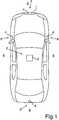
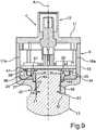
1 ein Kraftfahrzeug gemäß einer Ausführungsform der Erfindung, welches ein Kamerasystem mit mehreren Kameras aufweist;2 eine perspektivische Darstellung eines Ausführungsbeispiels einer erfindungsgemäßen Kamera;3 eine Explosionsdarstellung von zwei Teilkomponenten der Kamera gemäß2 ;4 eine Darstellung der Komponenten gemäß3 in einer zu3 unterschiedlichen Perspektive;5 die Darstellung der Komponenten gemäß3 und4 im miteinander verbauten Zustand;6 eine perspektivische Darstellung von Teilkomponenten der Kamera gemäß2 ;7 die Darstellung der Komponenten gemäß6 im miteinander verbauten Zustand;8 eine weitere perspektivische Darstellung von Bauteilen der Kamera gemäß2 mit einer in dem Gehäuse bereits verbauten Leiterplatte der Kamera;9 eine Vertikalschnittdarstellung der Kamera gemäß2 ; und10 eine Darstellung eines Teilbereichs einer weiteren Vertikalschnittdarstellung eines Ausführungsbeispiels einer Kamera gemäß der Erfindung.
1 a motor vehicle according to an embodiment of the invention, which has a camera system with a plurality of cameras;2 a perspective view of an embodiment of a camera according to the invention;3 an exploded view of two sub-components of the camera according to2 ;4th a representation of the components according to3 in one too3 different perspective;5 the representation of the components according to3 and4th when installed together;6th a perspective view of subcomponents of the camera according to FIG2 ;7th the representation of the components according to6th when installed together;8th a further perspective illustration of components of the camera according to FIG2 with a printed circuit board of the camera already installed in the housing;9 a vertical sectional view of the camera according to2 ; and10 a representation of a portion of a further vertical sectional view of an embodiment of a camera according to the invention.
In den Figuren werden gleiche und funktionsgleiche Elemente mit den gleichen Bezugszeichen versehen.Identical and functionally identical elements are provided with the same reference symbols in the figures.
Es kann zusätzlich oder anstatt dazu auch zumindest eine Kamera vorgesehen sein, die zur Erfassung eines Innenraums beziehungsweise eines Fahrgastraums des Kraftfahrzeugs
Mit den Kameras
In
In
Der Gehäusefrontflansch
Die Kamera
Darüber hinaus ist in
In
Darüber hinaus weist der Leiterplattenträger
Darüber hinaus ist in
Durch diese Klemmelemente
In
Insbesondere ist vorgesehen, dass der Leiterplattenträger
In
In einer vorteilhaften Ausführung weist die Kamera
Der Haltering
In einer weiteren Ausführung kann vorgesehen sein, dass der Haltering
In einer Ausführung kann vorgesehen sein, dass der Haltering
In
In
In
Wie darüber hinaus in
In
In
Dieses Staubschutzelement
ZITATE ENTHALTEN IN DER BESCHREIBUNGQUOTES INCLUDED IN THE DESCRIPTION
Diese Liste der vom Anmelder aufgeführten Dokumente wurde automatisiert erzeugt und ist ausschließlich zur besseren Information des Lesers aufgenommen. Die Liste ist nicht Bestandteil der deutschen Patent- bzw. Gebrauchsmusteranmeldung. Das DPMA übernimmt keinerlei Haftung für etwaige Fehler oder Auslassungen.This list of the documents listed by the applicant was generated automatically and is included solely for the better information of the reader. The list is not part of the German patent or utility model application. The DPMA assumes no liability for any errors or omissions.
Zitierte PatentliteraturPatent literature cited
- US 2010/0097519 A1 [0002]US 2010/0097519 A1 [0002]
Claims (15)
Translated fromGermanPriority Applications (5)
| Application Number | Priority Date | Filing Date | Title |
|---|---|---|---|
| DE102020102694.3ADE102020102694A1 (en) | 2020-02-04 | 2020-02-04 | Camera for a motor vehicle with a housing and a separate, electrically conductive printed circuit board carrier, and method |
| CN202180017594.5ACN115191109B (en) | 2020-02-04 | 2021-01-25 | Method for assembling camera and housing and camera |
| US17/797,512US12206973B2 (en) | 2020-02-04 | 2021-01-25 | Camera for a motor vehicle with a housing and an electrically conductive circuit board carrier separate thereto as well as method |
| EP21701787.0AEP4101155A1 (en) | 2020-02-04 | 2021-01-25 | Camera for a motor vehicle with a housing and an electrically conductive circuit board carrier separate thereto as well as method |
| PCT/EP2021/051551WO2021156080A1 (en) | 2020-02-04 | 2021-01-25 | Camera for a motor vehicle with a housing and an electrically conductive circuit board carrier separate thereto as well as method |
Applications Claiming Priority (1)
| Application Number | Priority Date | Filing Date | Title |
|---|---|---|---|
| DE102020102694.3ADE102020102694A1 (en) | 2020-02-04 | 2020-02-04 | Camera for a motor vehicle with a housing and a separate, electrically conductive printed circuit board carrier, and method |
Publications (1)
| Publication Number | Publication Date |
|---|---|
| DE102020102694A1true DE102020102694A1 (en) | 2021-08-05 |
Family
ID=74236212
Family Applications (1)
| Application Number | Title | Priority Date | Filing Date |
|---|---|---|---|
| DE102020102694.3APendingDE102020102694A1 (en) | 2020-02-04 | 2020-02-04 | Camera for a motor vehicle with a housing and a separate, electrically conductive printed circuit board carrier, and method |
Country Status (5)
| Country | Link |
|---|---|
| US (1) | US12206973B2 (en) |
| EP (1) | EP4101155A1 (en) |
| CN (1) | CN115191109B (en) |
| DE (1) | DE102020102694A1 (en) |
| WO (1) | WO2021156080A1 (en) |
Cited By (3)
| Publication number | Priority date | Publication date | Assignee | Title |
|---|---|---|---|---|
| DE102021132880A1 (en) | 2021-12-14 | 2023-06-15 | Connaught Electronics Ltd. | Motor vehicle camera with alignment aid |
| DE102022105428A1 (en) | 2022-03-08 | 2023-09-14 | Connaught Electronics Ltd. | Vehicle camera with threaded lens housing |
| DE102023112611A1 (en) | 2023-05-12 | 2024-11-14 | Connaught Electronics Ltd. | Camera for a motor vehicle, in which a circuit board has recesses in partial areas adjacent to fixing openings, and motor vehicle |
Citations (3)
| Publication number | Priority date | Publication date | Assignee | Title |
|---|---|---|---|---|
| DE10342526A1 (en) | 2003-09-12 | 2005-04-28 | Bosch Gmbh Robert | Camera for motor vehicle, has casing enclosing printing wiring board whose supporting surface supports imaging chip |
| US20100097519A1 (en) | 2008-10-16 | 2010-04-22 | Byrne Steven V | Compact Camera and Cable System for Vehicular Applications |
| US20190222726A1 (en) | 2016-09-27 | 2019-07-18 | SZ DJI Technology Co., Ltd. | Camera and photography assembly |
Family Cites Families (5)
| Publication number | Priority date | Publication date | Assignee | Title |
|---|---|---|---|---|
| CN106664358B (en)* | 2014-08-01 | 2020-06-05 | 日本电产科宝株式会社 | Image pickup device, optical device, electronic device, vehicle, and method of manufacturing the image pickup device |
| CN105629626A (en)* | 2014-11-05 | 2016-06-01 | 惠州友华微电子科技有限公司 | Camera, optical system and optical image stabilization camera apparatus |
| JP6768825B2 (en)* | 2016-03-16 | 2020-10-14 | ジェンテックス コーポレイション | Camera assembly with occluded image sensor circuit |
| US10477080B2 (en)* | 2016-07-07 | 2019-11-12 | Magna Electronics Inc. | Camera with curled lid and spring element for PCB positioning |
| EP3816723B1 (en)* | 2019-10-28 | 2023-09-20 | Ficosa Adas, S.L.U. | Motor vehicle camera assembly |
- 2020
- 2020-02-04DEDE102020102694.3Apatent/DE102020102694A1/enactivePending
- 2021
- 2021-01-25USUS17/797,512patent/US12206973B2/enactiveActive
- 2021-01-25WOPCT/EP2021/051551patent/WO2021156080A1/ennot_activeCeased
- 2021-01-25EPEP21701787.0Apatent/EP4101155A1/enactivePending
- 2021-01-25CNCN202180017594.5Apatent/CN115191109B/enactiveActive
Patent Citations (3)
| Publication number | Priority date | Publication date | Assignee | Title |
|---|---|---|---|---|
| DE10342526A1 (en) | 2003-09-12 | 2005-04-28 | Bosch Gmbh Robert | Camera for motor vehicle, has casing enclosing printing wiring board whose supporting surface supports imaging chip |
| US20100097519A1 (en) | 2008-10-16 | 2010-04-22 | Byrne Steven V | Compact Camera and Cable System for Vehicular Applications |
| US20190222726A1 (en) | 2016-09-27 | 2019-07-18 | SZ DJI Technology Co., Ltd. | Camera and photography assembly |
Cited By (4)
| Publication number | Priority date | Publication date | Assignee | Title |
|---|---|---|---|---|
| DE102021132880A1 (en) | 2021-12-14 | 2023-06-15 | Connaught Electronics Ltd. | Motor vehicle camera with alignment aid |
| WO2023110616A1 (en)* | 2021-12-14 | 2023-06-22 | Connaught Electronics Ltd. | Automotive camera with alignment support |
| DE102022105428A1 (en) | 2022-03-08 | 2023-09-14 | Connaught Electronics Ltd. | Vehicle camera with threaded lens housing |
| DE102023112611A1 (en) | 2023-05-12 | 2024-11-14 | Connaught Electronics Ltd. | Camera for a motor vehicle, in which a circuit board has recesses in partial areas adjacent to fixing openings, and motor vehicle |
Also Published As
| Publication number | Publication date |
|---|---|
| US12206973B2 (en) | 2025-01-21 |
| EP4101155A1 (en) | 2022-12-14 |
| US20230109282A1 (en) | 2023-04-06 |
| WO2021156080A1 (en) | 2021-08-12 |
| CN115191109B (en) | 2024-04-26 |
| CN115191109A (en) | 2022-10-14 |
Similar Documents
| Publication | Publication Date | Title |
|---|---|---|
| DE102017124550A1 (en) | Camera for a motor vehicle with at least two printed circuit boards and improved electromagnetic shielding, camera system, motor vehicle and manufacturing method | |
| DE69618090T2 (en) | Starter contactor with built-in electronic circuit, and motor vehicle starter with such contactor | |
| DE102020102694A1 (en) | Camera for a motor vehicle with a housing and a separate, electrically conductive printed circuit board carrier, and method | |
| DE102021113716A1 (en) | Camera for a motor vehicle with a specific seal between a front housing part and a circuit carrier, and motor vehicle | |
| DE102008053946A1 (en) | Shield shell unit | |
| DE112009001339T5 (en) | Electrical connection structure | |
| DE102021113714A1 (en) | Camera for a motor vehicle with specific lens heating, and motor vehicle | |
| DE102015107385A1 (en) | Method for producing a camera for a motor vehicle with electrical connection of a printed circuit board and a lens housing, camera, driver assistance system and motor vehicle | |
| DE102021103232B3 (en) | Connection device for an electrical and/or electronic device with a device housing and device housing arrangement and sensor arrangement | |
| DE102007010091A1 (en) | Connection method for vehicles, involves providing paint-corrosive element for mechanical attachment and electrical mass contacting of retained attachment part between paint-corrosive element and body part | |
| DE102014208487B4 (en) | Camera of an assistance system of a motor vehicle and method for producing such an assistance system | |
| DE112012000816B4 (en) | Lever connector and connector mounting plate | |
| DE102020214539A1 (en) | Adapter, radar unit and vehicle | |
| EP1170174A2 (en) | Snap mounting of a mirror drive unit | |
| DE102015110262A1 (en) | Camera for a motor vehicle with shielding device, driver assistance system and motor vehicle | |
| DE102007002193B4 (en) | Multi-part contacting component | |
| DE102020133708A1 (en) | Camera with specific cable connection, connection cable for a camera, system and method | |
| DE102019204290A1 (en) | Actuating drive device for adjusting an actuator, drive circuit for an actuator, manufacturing method for manufacturing a drive circuit and a motor vehicle component manufactured according to the method | |
| DE102019113081B4 (en) | Vehicle camera and method of assembling a vehicle camera | |
| DE102018102798B4 (en) | Camera for a motor vehicle with a specific housing screw connection, and motor vehicle | |
| DE10161102A1 (en) | Wire plug-in connector for transmitting electric power between a cable and a printed circuit board with strip conductors in a casing has a locked but detachable plug socket and a connector strip | |
| DE102019204291A1 (en) | Drive circuit for an actuator, actuator device for adjusting an actuator, manufacturing method for manufacturing a drive circuit and a motor vehicle component manufactured according to the method | |
| DE102020100360A1 (en) | Housing device for power electronics of a motor vehicle and a method for providing a housing device for power electronics of a motor vehicle | |
| DE102014107840A1 (en) | Modular Steering Column Module, Basic Module for a Modular Steering Column Module and Method of Making a Modular Steering Column Module | |
| DE102023118378A1 (en) | Camera with self-defining bendable mounting pin |
Legal Events
| Date | Code | Title | Description |
|---|---|---|---|
| R163 | Identified publications notified |