DE102020007212A1 - Method and hollow profile adsorber for treating a gas contaminated with harmful and / or useful components - Google Patents
Method and hollow profile adsorber for treating a gas contaminated with harmful and / or useful componentsDownload PDFInfo
- Publication number
- DE102020007212A1 DE102020007212A1DE102020007212.7ADE102020007212ADE102020007212A1DE 102020007212 A1DE102020007212 A1DE 102020007212A1DE 102020007212 ADE102020007212 ADE 102020007212ADE 102020007212 A1DE102020007212 A1DE 102020007212A1
- Authority
- DE
- Germany
- Prior art keywords
- flow
- gas
- pressure
- flow channels
- hollow profile
- Prior art date
- Legal status (The legal status is an assumption and is not a legal conclusion. Google has not performed a legal analysis and makes no representation as to the accuracy of the status listed.)
- Withdrawn
Links
Images


Classifications
- B—PERFORMING OPERATIONS; TRANSPORTING
- B01—PHYSICAL OR CHEMICAL PROCESSES OR APPARATUS IN GENERAL
- B01D—SEPARATION
- B01D53/00—Separation of gases or vapours; Recovering vapours of volatile solvents from gases; Chemical or biological purification of waste gases, e.g. engine exhaust gases, smoke, fumes, flue gases, aerosols
- B01D53/02—Separation of gases or vapours; Recovering vapours of volatile solvents from gases; Chemical or biological purification of waste gases, e.g. engine exhaust gases, smoke, fumes, flue gases, aerosols by adsorption, e.g. preparative gas chromatography
- B01D53/04—Separation of gases or vapours; Recovering vapours of volatile solvents from gases; Chemical or biological purification of waste gases, e.g. engine exhaust gases, smoke, fumes, flue gases, aerosols by adsorption, e.g. preparative gas chromatography with stationary adsorbents
- B01D53/0407—Constructional details of adsorbing systems
- B01D53/0438—Cooling or heating systems
- B—PERFORMING OPERATIONS; TRANSPORTING
- B01—PHYSICAL OR CHEMICAL PROCESSES OR APPARATUS IN GENERAL
- B01D—SEPARATION
- B01D53/00—Separation of gases or vapours; Recovering vapours of volatile solvents from gases; Chemical or biological purification of waste gases, e.g. engine exhaust gases, smoke, fumes, flue gases, aerosols
- B01D53/02—Separation of gases or vapours; Recovering vapours of volatile solvents from gases; Chemical or biological purification of waste gases, e.g. engine exhaust gases, smoke, fumes, flue gases, aerosols by adsorption, e.g. preparative gas chromatography
- B01D53/04—Separation of gases or vapours; Recovering vapours of volatile solvents from gases; Chemical or biological purification of waste gases, e.g. engine exhaust gases, smoke, fumes, flue gases, aerosols by adsorption, e.g. preparative gas chromatography with stationary adsorbents
- B01D53/0407—Constructional details of adsorbing systems
- B01D53/0446—Means for feeding or distributing gases
- B—PERFORMING OPERATIONS; TRANSPORTING
- B01—PHYSICAL OR CHEMICAL PROCESSES OR APPARATUS IN GENERAL
- B01D—SEPARATION
- B01D53/00—Separation of gases or vapours; Recovering vapours of volatile solvents from gases; Chemical or biological purification of waste gases, e.g. engine exhaust gases, smoke, fumes, flue gases, aerosols
- B01D53/02—Separation of gases or vapours; Recovering vapours of volatile solvents from gases; Chemical or biological purification of waste gases, e.g. engine exhaust gases, smoke, fumes, flue gases, aerosols by adsorption, e.g. preparative gas chromatography
- B01D53/04—Separation of gases or vapours; Recovering vapours of volatile solvents from gases; Chemical or biological purification of waste gases, e.g. engine exhaust gases, smoke, fumes, flue gases, aerosols by adsorption, e.g. preparative gas chromatography with stationary adsorbents
- B01D53/0462—Temperature swing adsorption
- B—PERFORMING OPERATIONS; TRANSPORTING
- B01—PHYSICAL OR CHEMICAL PROCESSES OR APPARATUS IN GENERAL
- B01D—SEPARATION
- B01D53/00—Separation of gases or vapours; Recovering vapours of volatile solvents from gases; Chemical or biological purification of waste gases, e.g. engine exhaust gases, smoke, fumes, flue gases, aerosols
- B01D53/34—Chemical or biological purification of waste gases
- B01D53/46—Removing components of defined structure
- B01D53/72—Organic compounds not provided for in groups B01D53/48 - B01D53/70, e.g. hydrocarbons
- B—PERFORMING OPERATIONS; TRANSPORTING
- B01—PHYSICAL OR CHEMICAL PROCESSES OR APPARATUS IN GENERAL
- B01D—SEPARATION
- B01D53/00—Separation of gases or vapours; Recovering vapours of volatile solvents from gases; Chemical or biological purification of waste gases, e.g. engine exhaust gases, smoke, fumes, flue gases, aerosols
- B01D53/34—Chemical or biological purification of waste gases
- B01D53/74—General processes for purification of waste gases; Apparatus or devices specially adapted therefor
- B01D53/81—Solid phase processes
- B01D53/82—Solid phase processes with stationary reactants
- B—PERFORMING OPERATIONS; TRANSPORTING
- B01—PHYSICAL OR CHEMICAL PROCESSES OR APPARATUS IN GENERAL
- B01J—CHEMICAL OR PHYSICAL PROCESSES, e.g. CATALYSIS OR COLLOID CHEMISTRY; THEIR RELEVANT APPARATUS
- B01J19/00—Chemical, physical or physico-chemical processes in general; Their relevant apparatus
- B01J19/24—Stationary reactors without moving elements inside
- B01J19/248—Reactors comprising multiple separated flow channels
- B01J19/249—Plate-type reactors
- B—PERFORMING OPERATIONS; TRANSPORTING
- B01—PHYSICAL OR CHEMICAL PROCESSES OR APPARATUS IN GENERAL
- B01J—CHEMICAL OR PHYSICAL PROCESSES, e.g. CATALYSIS OR COLLOID CHEMISTRY; THEIR RELEVANT APPARATUS
- B01J19/00—Chemical, physical or physico-chemical processes in general; Their relevant apparatus
- B01J19/32—Packing elements in the form of grids or built-up elements for forming a unit or module inside the apparatus for mass or heat transfer
- F—MECHANICAL ENGINEERING; LIGHTING; HEATING; WEAPONS; BLASTING
- F28—HEAT EXCHANGE IN GENERAL
- F28D—HEAT-EXCHANGE APPARATUS, NOT PROVIDED FOR IN ANOTHER SUBCLASS, IN WHICH THE HEAT-EXCHANGE MEDIA DO NOT COME INTO DIRECT CONTACT
- F28D21/00—Heat-exchange apparatus not covered by any of the groups F28D1/00 - F28D20/00
- F28D21/0015—Heat and mass exchangers, e.g. with permeable walls
- F—MECHANICAL ENGINEERING; LIGHTING; HEATING; WEAPONS; BLASTING
- F28—HEAT EXCHANGE IN GENERAL
- F28D—HEAT-EXCHANGE APPARATUS, NOT PROVIDED FOR IN ANOTHER SUBCLASS, IN WHICH THE HEAT-EXCHANGE MEDIA DO NOT COME INTO DIRECT CONTACT
- F28D9/00—Heat-exchange apparatus having stationary plate-like or laminated conduit assemblies for both heat-exchange media, the media being in contact with different sides of a conduit wall
- F28D9/0025—Heat-exchange apparatus having stationary plate-like or laminated conduit assemblies for both heat-exchange media, the media being in contact with different sides of a conduit wall the conduits being formed by zig-zag bend plates
- F—MECHANICAL ENGINEERING; LIGHTING; HEATING; WEAPONS; BLASTING
- F28—HEAT EXCHANGE IN GENERAL
- F28D—HEAT-EXCHANGE APPARATUS, NOT PROVIDED FOR IN ANOTHER SUBCLASS, IN WHICH THE HEAT-EXCHANGE MEDIA DO NOT COME INTO DIRECT CONTACT
- F28D9/00—Heat-exchange apparatus having stationary plate-like or laminated conduit assemblies for both heat-exchange media, the media being in contact with different sides of a conduit wall
- F28D9/0031—Heat-exchange apparatus having stationary plate-like or laminated conduit assemblies for both heat-exchange media, the media being in contact with different sides of a conduit wall the conduits for one heat-exchange medium being formed by paired plates touching each other
- F—MECHANICAL ENGINEERING; LIGHTING; HEATING; WEAPONS; BLASTING
- F28—HEAT EXCHANGE IN GENERAL
- F28D—HEAT-EXCHANGE APPARATUS, NOT PROVIDED FOR IN ANOTHER SUBCLASS, IN WHICH THE HEAT-EXCHANGE MEDIA DO NOT COME INTO DIRECT CONTACT
- F28D9/00—Heat-exchange apparatus having stationary plate-like or laminated conduit assemblies for both heat-exchange media, the media being in contact with different sides of a conduit wall
- F28D9/0062—Heat-exchange apparatus having stationary plate-like or laminated conduit assemblies for both heat-exchange media, the media being in contact with different sides of a conduit wall the conduits for one heat-exchange medium being formed by spaced plates with inserted elements
- F28D9/0075—Heat-exchange apparatus having stationary plate-like or laminated conduit assemblies for both heat-exchange media, the media being in contact with different sides of a conduit wall the conduits for one heat-exchange medium being formed by spaced plates with inserted elements the plates having openings therein for circulation of the heat-exchange medium from one conduit to another
- F—MECHANICAL ENGINEERING; LIGHTING; HEATING; WEAPONS; BLASTING
- F28—HEAT EXCHANGE IN GENERAL
- F28F—DETAILS OF HEAT-EXCHANGE AND HEAT-TRANSFER APPARATUS, OF GENERAL APPLICATION
- F28F3/00—Plate-like or laminated elements; Assemblies of plate-like or laminated elements
- F28F3/02—Elements or assemblies thereof with means for increasing heat-transfer area, e.g. with fins, with recesses, with corrugations
- F28F3/04—Elements or assemblies thereof with means for increasing heat-transfer area, e.g. with fins, with recesses, with corrugations the means being integral with the element
- F28F3/048—Elements or assemblies thereof with means for increasing heat-transfer area, e.g. with fins, with recesses, with corrugations the means being integral with the element in the form of ribs integral with the element or local variations in thickness of the element, e.g. grooves, microchannels
- B—PERFORMING OPERATIONS; TRANSPORTING
- B01—PHYSICAL OR CHEMICAL PROCESSES OR APPARATUS IN GENERAL
- B01D—SEPARATION
- B01D2253/00—Adsorbents used in seperation treatment of gases and vapours
- B01D2253/10—Inorganic adsorbents
- B01D2253/102—Carbon
- B—PERFORMING OPERATIONS; TRANSPORTING
- B01—PHYSICAL OR CHEMICAL PROCESSES OR APPARATUS IN GENERAL
- B01D—SEPARATION
- B01D2253/00—Adsorbents used in seperation treatment of gases and vapours
- B01D2253/10—Inorganic adsorbents
- B01D2253/104—Alumina
- B—PERFORMING OPERATIONS; TRANSPORTING
- B01—PHYSICAL OR CHEMICAL PROCESSES OR APPARATUS IN GENERAL
- B01D—SEPARATION
- B01D2253/00—Adsorbents used in seperation treatment of gases and vapours
- B01D2253/10—Inorganic adsorbents
- B01D2253/106—Silica or silicates
- B—PERFORMING OPERATIONS; TRANSPORTING
- B01—PHYSICAL OR CHEMICAL PROCESSES OR APPARATUS IN GENERAL
- B01D—SEPARATION
- B01D2253/00—Adsorbents used in seperation treatment of gases and vapours
- B01D2253/10—Inorganic adsorbents
- B01D2253/106—Silica or silicates
- B01D2253/108—Zeolites
- B—PERFORMING OPERATIONS; TRANSPORTING
- B01—PHYSICAL OR CHEMICAL PROCESSES OR APPARATUS IN GENERAL
- B01D—SEPARATION
- B01D2257/00—Components to be removed
- B01D2257/70—Organic compounds not provided for in groups B01D2257/00 - B01D2257/602
- B01D2257/704—Solvents not covered by groups B01D2257/702 - B01D2257/7027
- B—PERFORMING OPERATIONS; TRANSPORTING
- B01—PHYSICAL OR CHEMICAL PROCESSES OR APPARATUS IN GENERAL
- B01D—SEPARATION
- B01D2257/00—Components to be removed
- B01D2257/70—Organic compounds not provided for in groups B01D2257/00 - B01D2257/602
- B01D2257/708—Volatile organic compounds V.O.C.'s
- B—PERFORMING OPERATIONS; TRANSPORTING
- B01—PHYSICAL OR CHEMICAL PROCESSES OR APPARATUS IN GENERAL
- B01D—SEPARATION
- B01D2258/00—Sources of waste gases
- B01D2258/06—Polluted air
- B—PERFORMING OPERATIONS; TRANSPORTING
- B01—PHYSICAL OR CHEMICAL PROCESSES OR APPARATUS IN GENERAL
- B01J—CHEMICAL OR PHYSICAL PROCESSES, e.g. CATALYSIS OR COLLOID CHEMISTRY; THEIR RELEVANT APPARATUS
- B01J2219/00—Chemical, physical or physico-chemical processes in general; Their relevant apparatus
- B01J2219/24—Stationary reactors without moving elements inside
- B01J2219/2401—Reactors comprising multiple separate flow channels
- B01J2219/245—Plate-type reactors
- B01J2219/2451—Geometry of the reactor
- B01J2219/2456—Geometry of the plates
- B01J2219/2459—Corrugated plates
- B—PERFORMING OPERATIONS; TRANSPORTING
- B01—PHYSICAL OR CHEMICAL PROCESSES OR APPARATUS IN GENERAL
- B01J—CHEMICAL OR PHYSICAL PROCESSES, e.g. CATALYSIS OR COLLOID CHEMISTRY; THEIR RELEVANT APPARATUS
- B01J2219/00—Chemical, physical or physico-chemical processes in general; Their relevant apparatus
- B01J2219/24—Stationary reactors without moving elements inside
- B01J2219/2401—Reactors comprising multiple separate flow channels
- B01J2219/245—Plate-type reactors
- B01J2219/2461—Heat exchange aspects
- B—PERFORMING OPERATIONS; TRANSPORTING
- B01—PHYSICAL OR CHEMICAL PROCESSES OR APPARATUS IN GENERAL
- B01J—CHEMICAL OR PHYSICAL PROCESSES, e.g. CATALYSIS OR COLLOID CHEMISTRY; THEIR RELEVANT APPARATUS
- B01J2219/00—Chemical, physical or physico-chemical processes in general; Their relevant apparatus
- B01J2219/24—Stationary reactors without moving elements inside
- B01J2219/2401—Reactors comprising multiple separate flow channels
- B01J2219/245—Plate-type reactors
- B01J2219/2476—Construction materials
- B01J2219/2477—Construction materials of the catalysts
- B01J2219/2481—Catalysts in granular from between plates
- B—PERFORMING OPERATIONS; TRANSPORTING
- B01—PHYSICAL OR CHEMICAL PROCESSES OR APPARATUS IN GENERAL
- B01J—CHEMICAL OR PHYSICAL PROCESSES, e.g. CATALYSIS OR COLLOID CHEMISTRY; THEIR RELEVANT APPARATUS
- B01J2219/00—Chemical, physical or physico-chemical processes in general; Their relevant apparatus
- B01J2219/32—Details relating to packing elements in the form of grids or built-up elements for forming a unit of module inside the apparatus for mass or heat transfer
- B01J2219/322—Basic shape of the elements
- B01J2219/32203—Sheets
- B01J2219/3221—Corrugated sheets
- B—PERFORMING OPERATIONS; TRANSPORTING
- B01—PHYSICAL OR CHEMICAL PROCESSES OR APPARATUS IN GENERAL
- B01J—CHEMICAL OR PHYSICAL PROCESSES, e.g. CATALYSIS OR COLLOID CHEMISTRY; THEIR RELEVANT APPARATUS
- B01J2219/00—Chemical, physical or physico-chemical processes in general; Their relevant apparatus
- B01J2219/32—Details relating to packing elements in the form of grids or built-up elements for forming a unit of module inside the apparatus for mass or heat transfer
- B01J2219/322—Basic shape of the elements
- B01J2219/32203—Sheets
- B01J2219/32248—Sheets comprising areas that are raised or sunken from the plane of the sheet
- B01J2219/32251—Dimples, bossages, protrusions
- B—PERFORMING OPERATIONS; TRANSPORTING
- B01—PHYSICAL OR CHEMICAL PROCESSES OR APPARATUS IN GENERAL
- B01J—CHEMICAL OR PHYSICAL PROCESSES, e.g. CATALYSIS OR COLLOID CHEMISTRY; THEIR RELEVANT APPARATUS
- B01J2219/00—Chemical, physical or physico-chemical processes in general; Their relevant apparatus
- B01J2219/32—Details relating to packing elements in the form of grids or built-up elements for forming a unit of module inside the apparatus for mass or heat transfer
- B01J2219/322—Basic shape of the elements
- B01J2219/32279—Tubes or cylinders
- B—PERFORMING OPERATIONS; TRANSPORTING
- B01—PHYSICAL OR CHEMICAL PROCESSES OR APPARATUS IN GENERAL
- B01J—CHEMICAL OR PHYSICAL PROCESSES, e.g. CATALYSIS OR COLLOID CHEMISTRY; THEIR RELEVANT APPARATUS
- B01J2219/00—Chemical, physical or physico-chemical processes in general; Their relevant apparatus
- B01J2219/32—Details relating to packing elements in the form of grids or built-up elements for forming a unit of module inside the apparatus for mass or heat transfer
- B01J2219/324—Composition or microstructure of the elements
- B01J2219/32466—Composition or microstructure of the elements comprising catalytically active material
- B01J2219/32475—Composition or microstructure of the elements comprising catalytically active material involving heat exchange
Landscapes
- Engineering & Computer Science (AREA)
- Chemical & Material Sciences (AREA)
- Chemical Kinetics & Catalysis (AREA)
- Physics & Mathematics (AREA)
- Analytical Chemistry (AREA)
- General Chemical & Material Sciences (AREA)
- Oil, Petroleum & Natural Gas (AREA)
- Thermal Sciences (AREA)
- Mechanical Engineering (AREA)
- General Engineering & Computer Science (AREA)
- Environmental & Geological Engineering (AREA)
- Organic Chemistry (AREA)
- Biomedical Technology (AREA)
- Health & Medical Sciences (AREA)
- Separation Of Gases By Adsorption (AREA)
- Sorption Type Refrigeration Machines (AREA)
- Physical Or Chemical Processes And Apparatus (AREA)
- Devices And Processes Conducted In The Presence Of Fluids And Solid Particles (AREA)
Abstract
Translated fromGermanDescription
Translated fromGermanDie Erfindung betrifft ein Verfahren zum Behandeln eines mit mindestens einer gasförmigen Schad- und/oder Nutzkomponente belasteten Rohgases, bei dem das von einem Gebläse und/oder Verdichter unter einem erhöhten Adsorptionsdruck gesetzte Rohgas über einen zuströmseitigen Verteilraum eine Vielzahl von aus offenendigen, mit Adsorptionsmittel gefüllten Strömungskanälen in parallel aufgeteilten Teilströmen solange durchströmt, bis das Adsorptionsmittel durch Adsorption mit der Schad- und/oder Nutzkomponente gesättigt ist, wobei die bei der Adsorption entstehende Wärme durch ein im Kreuzstrom zu den Strömungskanälen geführtes Kühlmedium indirekt abgeführt wird, und die Teilströme nach ihrem Verlassen der Strömungskanäle in einem abströmseitigen Sammelraum zusammengeführt und als Reingas über eine Reingasleitung abgeführt werden, sodann das in den Strömungskanälen befindliche gesättigte Adsorptionsmittel regeneriert wird, indem das Adsorptionsmittel einem unter dem Adsorptionsdruck des Rohgases liegenden Desorptionsdruck ausgesetzt und gleichzeitig durch ein im Kreuzstrom zu den Strömungskanälen geführtes Heizmedium indirekt erhitzt wird bis die Schad- und/oder Nutzkomponente desorbiert, die zusammen mit einem Spülgas als aufgeheiztes Desorbat abgeführt wird, wobei eine Steuereinheit in Abhängigkeit der Beladung des Adsorptionsmittels die Strömungskanäle des einen Adsorbers vom Adsorptions- in den Regenerationszustand oder umgekehrt auf einen weiteren Adsorber umschaltet,The invention relates to a method for treating a crude gas loaded with at least one gaseous pollutant and / or useful component, in which the crude gas set by a fan and / or compressor under an increased adsorption pressure has a large number of open-ended adsorbents filled with an upstream distribution chamber Flows through flow channels in parallel divided partial flows until the adsorbent is saturated by adsorption with the harmful and / or useful component, with the heat generated during adsorption being carried away indirectly by a cooling medium conducted in cross flow to the flow channels, and the partial flows after they have left of the flow channels are brought together in a collecting space on the downstream side and discharged as clean gas via a clean gas line, then the saturated adsorbent located in the flow channels is regenerated by the adsorbent under the adsorption pressure of the raw gas ases is exposed to the desorption pressure and at the same time is indirectly heated by a heating medium conducted in a cross flow to the flow channels until the harmful and / or useful component is desorbed, which is discharged together with a flushing gas as heated desorbate, with a control unit opening the flow channels depending on the loading of the adsorbent one adsorber switches from adsorption to regeneration or vice versa to another adsorber,
Die Erfindung betrifft weiterhin einen Hohlprofiladsorber mit einer Vielzahl von aus Hohlprofilen gebildeten Strömungskanälen und zu diesen im Kreuzstrom verlaufende Strömungsräume, wobei die mit Adsorptionsmittel befüllten Strömungskanäle für den Durchtritt des in Teilströme aufgeteilten Rohgases in einen zuströmseitigen, an eine Zuführleitung angeschlossenen, Verteilraum und einen abströmseitigen an eine Reingasleitung angeschlossenen Sammelraum münden, die durch die Strömungskanäle durchströmungsoffen verbunden sind, und die Strömungsräume in einen die Strömungskanäle umschließenden Verteilraum für das Zu- und Abführen eines Kühl- oder Heizmediums zum indirekten Kühlen oder Heizen des Adsorptionsmittels durchströmungsoffen münden, und mit einer Steuereinheit, die den mit der Schad- und/oder Nutzkomponente beladenen Hohlprofiladsorber aus dem Adsorptions- in den Regenerationszustand oder umgekehrt umschaltet.The invention further relates to a hollow profile adsorber with a plurality of flow channels formed from hollow profiles and flow spaces running in cross flow to these, the flow channels filled with adsorbent for the passage of the raw gas divided into partial flows into an inflow side, connected to a supply line, distribution space and an outflow side a clean gas line connected collecting space, which are connected through the flow channels, and the flow spaces in a distribution space surrounding the flow channels for the supply and discharge of a cooling or heating medium for indirect cooling or heating of the adsorbent open-flow, and with a control unit that switches the hollow profile adsorber loaded with the harmful and / or useful component from the adsorption to the regeneration state or vice versa.
Stand der TechnikState of the art
Schadstoffe in Gasen an Adsorbentien zu adsorbieren und diese für einen neuen Adsorptionsvorgang zu regenerieren, gehören seit langem zum Stand der Technik. Zum Einsatz kommen hauptsächlich Adsorbentien in Form von Schüttungen aus Aktivkohle, Silica-Gel, Aluminiumoxid-Gel oder Molekularsiebe, die beispielsweise in einer vom zu reinigenden Gas durchströmten Schüttung (
Bei der klassischen Adsorption durchströmt das zu reinigende Gas den mit Adsorptionsmittel gefüllten Adsorber, wobei das Adsorptionsmittel den Schadstoff adsorbiert und durch die Adsorption Wärme entsteht, die bei herkömmlichen Adsorbern nicht abgeführt werden kann. Das zu reinigende Gas wird deshalb vor Eintritt in den Adsorber gekühlt.
Während der Adsorption entsteht im Adsorber daher ein Temperaturprofil, d.h. bei abwärts gerichteter Strömungsrichtung des Gases durch die Adsorptionsmittelschüttung werden die oberen Schichten der Schüttung durch das eintretende Gas gekühlt und die unteren Schichten durch die freiwerdende Adsorptionswärme erwärmt. Grundsätzlich adsorbiert ein Stoff bei höherer Temperatur schlechter und die maximal mögliche Beladung des Adsorptionsmittels mit der adsorbierten Schadkomponente nimmt mit steigender Temperatur ab. Dies limitiert die Leistung der Festbettadsorber deutlich.
Das sich während der Adsorption von Lösemitteln ausbildende Temperaturprofil aus VOC-belasteter Abluft begünstigt außerdem die Ausbildung von brandgefährdenden Hotspots in der Aktivkohleschüttung, die zu einer Selbstentzündung der Aktivkohle führen können.
Bei der Regeneration wird bekanntlich in das beladene Adsorptionsmittel ein zuvor aufgeheiztes Regenerationsgas eingeleitet, welches das Adsorptionsmittel auf eine Temperatur erhitzt, bei dem der Schadstoff oder die Nutzkomponente desorbiert.
Die Regeneration mit Gas ist aufgrund der relativ geringen Wärmekapazität des Gases aus energetischer Sicht unvorteilhaft. Alle Apparate, Rohrleitungen und Armaturen werden vom erhitzten Regenerationsgas aufgeheizt, bevor die Wärme das Adsorptionsmittel entsprechend aufheizen kann. Dies verursacht hohe Betriebskosten durch die aufzuwendende Verlustenergie.With classic adsorption, the gas to be cleaned flows through the adsorber filled with adsorbent, the adsorbent adsorbing the pollutant and the adsorption generating heat that cannot be dissipated with conventional adsorbers. The gas to be cleaned is therefore cooled before it enters the adsorber.
During adsorption, a temperature profile is created in the adsorber, ie when the gas flows downwards through the adsorbent bed, the upper layers of the bed are cooled by the incoming gas and the lower layers are heated by the heat of adsorption released. Basically, a substance adsorbs worse at a higher temperature and the maximum possible loading of the adsorbent with the adsorbed harmful component decreases with increasing temperature. This significantly limits the performance of the fixed bed adsorber.
The temperature profile that develops from VOC-contaminated exhaust air during the adsorption of solvents also favors the formation of fire-endangering hotspots in the activated carbon bed, which can lead to spontaneous combustion of the activated carbon.
During the regeneration, as is known, a previously heated regeneration gas is introduced into the loaded adsorbent, which heats the adsorbent to a temperature at which the pollutant or the useful component desorbs.
Regeneration with gas is disadvantageous from an energetic point of view due to the relatively low heat capacity of the gas. All apparatus, pipes and fittings are heated up by the heated regeneration gas before the heat can heat up the adsorbent accordingly. This causes high operating costs due to the energy loss that has to be expended.
Aus der
Dieser Stand der Technik schlägt des Weiteren die Desorption der adsorbierten Verunreinigungen vom im Festbett angeordneten Adsorptionsmittel durch das Abstreifen mit einem Spülgas, das Verdrängen mit einem bevorzugt adsorbierten Material, das Erhitzen des Adsorptionsmittels auf eine Temperatur oberhalb der Adsorptionstemperatur auf direkten oder indirekten Weg oder auf einen Druck unterhalb des Adsorptionsdrucks vor.From the
This prior art also suggests the desorption of the adsorbed impurities from the adsorbent arranged in the fixed bed by stripping with a purge gas, the displacement with a preferably adsorbed material, the heating of the adsorbent to a temperature above the adsorption temperature in a direct or indirect way or in a Pressure below the adsorption pressure.
Wird Aktivkohle als Adsorptionsmittel bei der Lösemittelrückgewinnung eingesetzt, erfolgt die Regeneration der Aktivkohle meistens durch eine Direktbedampfung der Aktivkohle mit heißem Wasserdampf, wodurch neben den Wärmeverlusten zusätzlich eine Verunreinigung der Lösemittel durch den Dampf eintritt. Des Weiteren muss vor einer Wiederverwendung des Lösemittels die Wasserphase aus dem Lösemittel entfernt werden, was wiederum einen hohen energetischen und apparativen Aufwand verursacht.If activated carbon is used as an adsorbent for solvent recovery, the activated carbon is usually regenerated by direct steaming of the activated carbon with hot water vapor, which in addition to the heat losses also causes the solvent to be contaminated by the steam. Furthermore, before the solvent can be reused, the water phase must be removed from the solvent, which in turn causes high expenditure in terms of energy and equipment.
Neben der Anordnung der Adsorptionsmittel als Schüttung im Festbett oder der Anordnung der Adsorptionsmittel zwischen Wärmeaustauscherplatten ist auch die Aktivkohle-Befüllung von Rohren in einem Rohrbündel mit Kreisringquerschnitt (
Weiterhin ist aus der
Darüber hinaus sind Verfahren und Vorrichtungen zur Reinigung oder Trocknung von Gasen bekannt, in denen Rohrbündelwärmeaustauscher oder Rohranordnungen aus parallel angeordneten voneinander beabstandeten Rohren eingesetzt werden, die mit Adsorptionsmittel gefüllt sind.In addition, methods and devices for cleaning or drying gases are known, in which tube bundle heat exchangers or tube arrangements are used from tubes arranged in parallel and spaced from one another, which are filled with adsorbent.
In der
Nach diesem Stand der Technik gibt es zwei grundlegende Systeme, einen Katalysator oder ein Adsorbent in einen vom Prozessfluid durchströmten Strömungskanal einzubringen. Die erste Möglichkeit besteht darin, den Katalysator oder Adsorbent als geträgerte Schicht im Strömungskanals anzuordnen (
Beide Systeme sind mit gravierenden Nachteilen verbunden. Das erste System ist aufgrund seines komplizierten konstruktiven Aufbaus gewissermaßen ein Einwegsystem, weil der Katalysator bzw. das Adsorptionsmittel nach ihrem Verbrauch nur mit verhältnismäßig hohem technischem Aufwand entfernt werden können oder der Apparat sogar verschrottet werden muss.
Beim zweiten System ist eine Verblockung einzelner Strömungskanäle durch die in den Strömungskanälen befindliche Adsorptionsmittelschüttung sowohl während der Adsorption als auch der Regeneration nicht sicher auszuschließen, so dass eine ungleichmäßige Beladung des Adsorptionsmittels die Folge ist, die dazu führt, dass die Wirtschaftlichkeit des Verfahrens beeinträchtigt wird. Bei der Desorption kann die Restbeladung aus dem Adsorptionsmittel des verblockten Strömungskanals nicht vollständig ausgetrieben werden und die
Adsorptionskapazität für die folgende Adsorptionsphase reduziert sich entsprechend der Restbeladung, sofern der verblockte Strömungskanal wieder strömungsdurchgängig gemacht werden konnte. Außerdem erhöht sich der Verbrauch der Hohlprofile ausgebildet werden, wobei die Ausprägungen nach innen in den Strömungskanal und/oder nach außen in den Strömungsraum ausgerichtet sein können. Die erzeugten Turbulenzen wirken der Randgängigkeit entlang der Wandung der Strömungskanäle entgegen und haben außerdem den Vorteil, dass das Kühl- oder Heizmedium von den nach außen in die Strömungsräume gerichteten Ausprägungen direkt an der Oberfläche verwirbelt wird und so den Wärmeaustausch deutlich verbessert.Both systems have serious disadvantages. Due to its complicated construction, the first system is to a certain extent a one-way system, because the catalyst or the adsorbent can only be removed after it has been used up with a relatively high level of technical effort, or the apparatus even has to be scrapped.
In the second system, blockage of individual flow channels by the adsorbent bed located in the flow channels cannot be ruled out with certainty, both during adsorption and regeneration, so that uneven loading of the adsorbent is the result, which leads to the economic viability of the process being adversely affected. During the desorption, the residual load cannot be completely expelled from the adsorbent of the blocked flow channel and the
Adsorption capacity for the following adsorption phase is reduced accordingly Residual load, provided that the blocked flow channel could be made flow-permeable again. In addition, the consumption of the hollow profiles that are formed increases, it being possible for the expressions to be oriented inward into the flow channel and / or outward in the flow space. The generated turbulence counteracts the marginal accessibility along the wall of the flow channels and also has the advantage that the cooling or heating medium is swirled directly on the surface by the features directed outwards into the flow spaces and thus significantly improves the heat exchange.
Nach einer weiteren vorteilhaften Ausgestaltung des erfindungsgemäßen Verfahrens werden die Turbulenzen im Kühl- oder Heizmedium durch in den Strömungsräumen zwischen den Hohlprofilreihen positionierte Strömungsleit- oder Abstandbleche erzeugt, wobei das Kühlmedium während der Adsorption oder das Heizmedium während der Regeneration im Kreuzstrom zu den Strömungskanälen ein- oder mehrgängig geführt werden kann.
Für den Fall, dass das Kühl- oder Heizmedium mehrgängig geführt werden soll, werden benachbarte Strömungsräume wechselweise miteinander verbunden, wodurch das Kühl- oder Heizmedium von Strömungsraum zu Strömungsraum umgelenkt wird. Durch die Strömungsleit- und Abstandsbleche in den Strömungsräumen zwischen den Hohlprofilreihen wird eine ständige Umlenkung des an den Strömungskanälen vorbeiströmenden Kühl- oder Heizmediums erzwungen, so dass der indirekte Wärmeaustausch mit dem Adsorptionsmittel eine hohe Effektivität erreicht. Gleichzeitig stellen die Strömungsleit- und Abstandsbleche einen genauen Abstand der über- oder untereinanderliegenden Hohlprofilreihen sicher und ermöglichen eine stabile und kompakte Bauweise.According to a further advantageous embodiment of the method according to the invention, the turbulence in the cooling or heating medium is generated by flow guide or spacer plates positioned in the flow spaces between the rows of hollow profiles, the cooling medium being switched on or off during the regeneration in a cross flow to the flow channels can be run multiple times.
In the event that the cooling or heating medium is to be routed in several ways, adjacent flow spaces are alternately connected to one another, as a result of which the cooling or heating medium is diverted from flow space to flow space. The flow guide and spacer plates in the flow spaces between the rows of hollow profiles force a constant deflection of the cooling or heating medium flowing past the flow channels, so that the indirect heat exchange with the adsorbent is highly effective. At the same time, the flow guide and spacer plates ensure an exact distance between the rows of hollow profiles lying above or below one another and enable a stable and compact design.
In einer weiteren Ausgestaltung des erfindungsgemäßen Verfahrens wird der Adsorptionsdruck derart eingeregelt, dass der Druck des Rohgases im Verteilraum und der Druck des Reingases im Sammelraum durch mit der Steuereinheit verbundene Drucksensoren gemessen werden, die Steuereinheit die Messwerte mit einem vorgegebenen, in der Steuereinheit hinterlegten Sollwert für den Adsorptionsdruck vergleicht und bei Abweichung das Gebläse und/oder Verdichter und ein dem Sammelraum nachgeordnetes Druckregelventil ansteuert, welches den Abfluss an Reingas aus dem Sammelraum derart einstellt, dass der Adsorptionsdruck dem Sollwert für den Adsorptionsdruck entspricht.
Diese Regelungsweise ermöglicht es, den Adsorptionsdruck in den Strömungskanälen genau und sicher einzuhalten.In a further embodiment of the method according to the invention, the adsorption pressure is regulated in such a way that the pressure of the raw gas in the distribution chamber and the pressure of the pure gas in the collecting chamber are measured by pressure sensors connected to the control unit compares the adsorption pressure and, in the event of a deviation, controls the fan and / or compressor and a pressure control valve downstream of the collecting chamber, which adjusts the outflow of clean gas from the collecting chamber in such a way that the adsorption pressure corresponds to the setpoint for the adsorption pressure.
This control mode makes it possible to precisely and reliably maintain the adsorption pressure in the flow channels.
Gemäß einer weiteren bevorzugten Ausführungsform des erfindungsgemäßen Verfahrens wird der Desorptionsdruck derart eingeregelt, dass der Druck des Spülgases im Verteilraum und der anliegende Druck der Vakuumpumpe im Sammelraum durch mit der Steuereinheit verbundene Drucksensoren gemessen werden, die Steuereinheit die Messwerte mit einem vorgegebenen, in der Steuereinheit hinterlegten Sollwert für den Desorptionsdruck vergleicht und bei Abweichung die dem Sammelraum nachgeordnete Vakuumpumpe und ein dem Verteilraum vorgeordnetes Regelventil ansteuert, welches den Zufluss an Spülgas in den Verteilraum derart einstellt, dass der Desorptionsdruck dem Sollwert für den Desorptionsdruck entspricht.
Vor Vorteil ist, dass der Desorptionsdruck in den Strömungskanälen durch das Zusammenwirken von Vakuumpumpe und Regelventil exakt eingehalten werden kann.According to a further preferred embodiment of the method according to the invention, the desorption pressure is regulated in such a way that the pressure of the purging gas in the distribution chamber and the applied pressure of the vacuum pump in the collecting chamber are measured by pressure sensors connected to the control unit, the control unit storing the measured values with a predetermined value in the control unit Compares the setpoint for the desorption pressure and, in the event of a deviation, controls the vacuum pump downstream of the collecting chamber and a control valve upstream of the distribution chamber, which adjusts the flow of purging gas into the distribution chamber such that the desorption pressure corresponds to the setpoint for the desorption pressure.
The advantage is that the desorption pressure in the flow channels can be precisely maintained through the interaction of the vacuum pump and control valve.
Nach einer weiteren bevorzugten Ausgestaltungsform des erfindungsgemäßen Verfahren wird der der Kondensations-Überdruck derart eingeregelt, dass der Druck des Rückgases nach Verlassen des Wärmeaustauschers/Kondensators durch einen mit der Steuereinheit verbundenen Drucksensor gemessen wird, die Steuereinheit den Messwert mit einem vorgegebenen, in der Steuereinheit hinterlegten Sollwert für den Kondensations-Überdruck vergleicht und bei Abweichung ein dem Wärmeaustauscher/Kondensator nachgeordnetes Druckregelventil ansteuert, welches den Abfluss an Rückgas derart einstellt, dass der Kondensations-Überdruck dem Sollwert für den Kondensations-Überdruck entspricht.
Dies ermöglicht die genaue Einhaltung des Überdruckes während der Kondensation.According to a further preferred embodiment of the method according to the invention, the condensation overpressure is regulated in such a way that the pressure of the return gas is measured by a pressure sensor connected to the control unit after leaving the heat exchanger / condenser, and the control unit stores the measured value with a predetermined value in the control unit Compares the setpoint for the condensation overpressure and, if there is a deviation, controls a pressure control valve downstream of the heat exchanger / condenser, which adjusts the return gas flow so that the condensation overpressure corresponds to the setpoint for the condensation overpressure.
This enables the overpressure to be precisely maintained during the condensation.
In einer vorteilhaften Weiterbildung des erfindungsgemäßen Verfahrens wird als Spülgas Reingas oder Inertgas verwendet, das in Teilströme während der Regeneration aufgeteilt wird, wobei je ein Teilstrom in jeweils einen mit gesättigtem Adsorptionsmittel gefüllten Strömungskanal geleitet wird, diesen durchströmt und die desorbierte Schad- und/oder Nutzkomponente aus dem Adsorptionsmittel in den Sammelraum austrägt und zum Desorbat aus Spülgas und Schad- und/oder Nutzkomponente zusammengeführt wird.
Dadurch, dass die Teilströme des Spülgases nur noch Transportfunktion wahrnehmen, wird eine hohe Energieeffizienz während der Regeneration erreicht. Vorteilhafterweise kann von dem durch das erfindungsgemäße Verfahren erzeugte Reingas ein Teilstrom abgeteilt und als Spülgas verwendet werden. Im Fall, dass stattdessen Inertgas eingesetzt wird, ist ein entsprechender Speicher vorzusehen, von dem das Inertgas als Spülgas zugeführt wird. Alternativ dazu kann das Inertgas auch einem Versorgungsnetzwerk entnommen werden. Als Inertgas kommt vorzugsweise Stickstoff zum Einsatz.In an advantageous development of the method according to the invention, the flushing gas used is clean gas or inert gas, which is divided into partial flows during the regeneration, one partial flow each being passed into a flow channel filled with saturated adsorbent, flowing through this and the desorbed harmful and / or useful component discharges from the adsorbent into the collecting space and is combined to desorbate from flushing gas and harmful and / or useful components.
The fact that the partial flows of the purge gas only perform a transport function means that a high level of energy efficiency is achieved during regeneration. Advantageously, a partial flow can be separated from the clean gas generated by the method according to the invention and used as a flushing gas. In the event that inert gas is used instead, a corresponding reservoir is to be provided, from which the inert gas is supplied as a flushing gas. Alternatively, the inert gas can also be taken from a supply network. Nitrogen is preferably used as the inert gas.
Nach einer vorteilhaften Ausführungsvariante des erfindungsgemäßen Verfahrens werden Hohlprofile in Form von Rohren, Rechteck- oder Kastenprofilen aus dünnem Edelstahl-, Kupfer,- oder Aluminiumblech mit einer lichten Weite zwischen 3 bis 80 mm, einer Länge von 1 bis 2 m und einer Wanddicke von 0,2 bis 3 mm verwendet
Benachbarte Hohlprofile werden entlang einer zur Längsachse der Hohlprofile parallel verlaufenden Achse an ihrer äußeren Wand miteinander durch Laserlinienschweißen, Punktschweißen oder Hartlöten zu einer Hohlprofilreihe verbunden, wobei mehrere Hohlprofilreihen über- oder untereinander auf Lücke versetzt im Abstand voneinander angeordnet sind und zwischen sich jeweils einen Strömungsraum bilden, sodass das Kühlmedium während der Adsorption oder das Heizmedium während der Regeneration im Kreuzstrom zu den Strömungskanälen ein- oder mehrgängig geführt werden kann.
Als Kühlmedium kann Wasser oder Wasser-Glykol-Gemische und als Heizmedium Wasserdampf, heißes Wasser oder heiße Gase verwendet werden.According to an advantageous embodiment of the method according to the invention, hollow profiles in the form of tubes, rectangular or box profiles made of thin stainless steel, copper or aluminum sheet with a clear width between 3 to 80 mm, a length of 1 to 2 m and a wall thickness of 0 , 2 to 3 mm used
Adjacent hollow profiles are connected to one another along an axis running parallel to the longitudinal axis of the hollow profiles on their outer wall by laser line welding, spot welding or brazing to form a row of hollow profiles, with several rows of hollow profiles being arranged above or below one another with gaps at a distance from one another and each forming a flow space between them so that the cooling medium during the adsorption or the heating medium during the regeneration can be fed in cross-flow to the flow channels in one or more passages.
Water or water-glycol mixtures can be used as the cooling medium and water vapor, hot water or hot gases can be used as the heating medium.
Eine weitere Ausgestaltungsform des erfindungsgemäßen Verfahrens zeichnet sich dadurch aus, dass die verflüssigte Schad- und/oder Nutzkomponente über einen Kondensatablass abgeführt sowie das den Wärmeaustauscher verlassende Rückgas dem Rohgas zugemischt wird.Another embodiment of the method according to the invention is characterized in that the liquefied harmful and / or useful component is discharged via a condensate drain and the return gas leaving the heat exchanger is mixed with the raw gas.
Die weitere Ausgestaltung des erfindungsgemäßen Verfahrens sieht vor, dass als Adsorptionsmittel Schüttungen aus Aktivkohlegranulat, Aluminiumoxid-Gel, Silica-Gel, Molekularsiebe oder deren Gemische verwendet werden.The further embodiment of the method according to the invention provides that beds of activated carbon granulate, aluminum oxide gel, silica gel, molecular sieves or mixtures thereof are used as adsorbents.
Die Lösung der Aufgabe wird mit dem erfindungsgemäßen Hohlprofiladsorber dadurch erreicht, dass die Hohlprofile in mindestens zwei übereinander auf Versatz liegende Hohlprofilreihen zusammengefasst sind, die durch in den Strömungsräumen für das Kühl- oder Heizmedium angeordneten Strömungsleit- und Abstandsbleche voneinander beabstandet sind, wobei die Hohlprofile parallel nebeneinander entlang einer zur Längsachse der Hohlprofile senkrecht verlaufenden Achse auf Stoß liegen und im Stoß miteinander zumindest punktweise stoffschlüssig verbunden sind und dass die Strömungskanäle eine lichte Weite von mindestens 10 bis maximal 80 mm haben und im Inneren Strömungsschikanen zum Erzeugen von Turbulenzen aufweisen, und dass der zuströmseitige Verteilraum mit einer Spülgasleitung zum Zuführen des in Teilströmen aufgefächerten Spülgases und dessen Einleitung in die Strömungskanäle für den Abtransport der desorbierten aufgeheizten Schad- und/oder Nutzkomponente aus dem Adsorptionsmittel als Desorbat in den Sammelraum in Verbindung steht, wobei an die Spülgasleitung ein Regelventil zum Drosseln des Zuflusses an Spülgas in den Verteilraum und der Sammelraum abströmseitig an eine Vakuumpumpe saugseitig angeschlossen ist, und dass die Vakuumpumpe druckseitig mit einem Wärmeaustauscher/Kondensator zum Auftrennen des Desorbats in die Schad- und/oder Nutzkomponente und ein Rückgas verbunden ist, wobei der Wärmeaustauscher/Kondensator mit einem Abscheider zum Ausschleusen der Schad- und/oder Nutzkomponente und der Wärmeaustauscher mit einer Rückgasleitung zum Abführen des Rückgases in die Zuführleitung des Rohgases in Verbindung steht, wobei ein Druckregelventil zum Drosseln des Abflusses des Rückgases während der Kondensation in die Rückgasleitung eingebunden ist.The object is achieved with the hollow profile adsorber according to the invention in that the hollow profiles are combined in at least two offset rows of hollow profiles, which are spaced from one another by flow guide and spacer plates arranged in the flow spaces for the cooling or heating medium, the hollow profiles being parallel lie next to one another along an axis running perpendicular to the longitudinal axis of the hollow profiles and abut each other at least pointwise in the joint and that the flow channels have a clear width of at least 10 to a maximum of 80 mm and have flow chicanes inside to generate turbulence, and that the Inflow-side distribution space with a purging gas line for feeding the purging gas, which is fanned out in partial flows, and introducing it into the flow channels for the removal of the desorbed heated harmful and / or useful components from the adsorbent as desorber bat is connected to the collecting space, with a control valve on the flushing gas line for throttling the flow of flushing gas into the distribution space and the collecting space being connected on the outflow side to a vacuum pump on the suction side, and that the vacuum pump is connected on the pressure side with a heat exchanger / condenser for separating the desorbate into the Harmful and / or useful component and a return gas is connected, the heat exchanger / condenser being connected to a separator for discharging the harmful and / or useful component and the heat exchanger to a return gas line for discharging the return gas into the feed line for the raw gas, wherein a Pressure control valve for throttling the outflow of the return gas during the condensation is integrated into the return gas line.
Nach einer bevorzugten Ausgestaltungsform des erfindungsgemäßen Hohlprofiladsorbers umfasst das Strömungsleit- und Abstandsblech ein dünnes Wellblech mit in die Wellenberge eingeformte, die Höhe der Wellenberge übersteigende Abstandshalterprofile die zueinander von Wellenberg zu Wellenberg auf Lücke versetzt angeordnet sind, wobei die Abstandhalterprofile in den von den über- und untereinanderliegenden Hohlprofilreihen gebildeten Versatz abstützend eingreifen und das jeweilige Abstandshalterprofil jeweils endseitig an der dazugehörigen Hohlprofilreihe stoffschlüssig fixiert ist.
Dies hat den Vorteil, dass die Strömungsleit- und Abstandsbleche nicht nur die Turbulenzen im Kühl- oder Heizmedium erzeugen, sondern zugleich auch die aus den Hohlprofilreihen gebildeten Strömungskanäle zueinander auf Abstand halten, so dass das Kühlmedium während der Adsorption oder das Heizmedium während der Regeneration im Kreuzstrom zu den Strömungskanälen ein- oder mehrgängig ohne Behinderung durch die Strömungsräume geführt werden kann.According to a preferred embodiment of the hollow profile adsorber according to the invention, the flow guide and spacer sheet comprises a thin corrugated sheet with spacer profiles which are formed into the wave crests and exceed the height of the wave crests and are arranged offset to one another from wave crest to wave crest, with the spacer profiles in the from above and below intervening offset formed below one another in a supporting manner and the respective spacer profile is fixed in a materially bonded manner at the end of the associated row of hollow profiles.
This has the advantage that the flow guide and spacer plates not only generate the turbulence in the cooling or heating medium, but also keep the flow channels formed from the rows of hollow profiles at a distance from one another, so that the cooling medium during adsorption or the heating medium during regeneration in the Cross flow to the flow channels can be guided through the flow spaces with one or more passes without hindrance.
Wesentlich für die weitgehende Vermeidung einer Randgängigkeit der Teilströme in den Strömungskanälen am Adsorptionsmittel vorbei ist, dass die Strömungsschikanen durch Ausprägungen gebildet sind, die quer und/oder parallel zur Strömungsrichtung des Teilstroms des Rohgases oder Spülgases in die Wandung der Strömungskanäle nach innen und/oder von der Wand nach außen gerichtet eingeformt sind.In order to largely prevent the partial flows from passing along the edges of the flow channels past the adsorbent, it is essential that the flow chicanes are formed by features that are transverse and / or parallel to the flow direction of the partial flow of the raw gas or purging gas into the wall of the flow channels inwards and / or from are molded into the wall facing outwards.
In einer weiteren bevorzugten Ausgestaltung des erfindungsgemäßen Hohlprofiladsorbers ist dem Verteilraum und/oder dem Sammelraum jeweils ein Drucksensor zum Messen des Druckes des Rohgases, des Druckes des Reingases während der Adsorption und des Druckes des Spülgases und des saugseitigen Druckes der Vakuumpumpe während Regeneration zugeordnet ist, wobei die Drucksensoren mit der Steuereinheit verbunden sind, die zum Ansteuern des Gebläses in der Zuführleitung, des Druckregelventils zum Drosseln des Abflusses an Reingas aus dem Sammelraum, der Vakuumpumpe zum Erzeugen des Unterdrucks während der Regeneration und der Regelventile zum Drosseln des Zuflusses an Spülgas in den Verteilraum in Verbindung steht.In a further preferred embodiment of the hollow profile adsorber according to the invention, a pressure sensor for measuring the pressure of the raw gas, the pressure of the clean gas during adsorption and the pressure of the flushing gas and the suction-side pressure of the vacuum pump during regeneration is assigned to the distribution space and / or the collecting space, with the pressure sensors are connected to the control unit, which are used to control the fan in the supply line, the pressure control valve to throttle the outflow of clean gas from the collecting chamber, the vacuum pump to generate the negative pressure during the Regeneration and the control valves for throttling the flow of purge gas into the distribution chamber is in connection.
Nach einem weiteren Merkmal des erfindungsgemäßen Hohlprofiladsorbers ist der Wärmeaustauscher/Kondensator abströmseitig mit der Zufuhrleitung für das Rohgas durch die Rückgasleitung über das Druckregelventil zum Drosseln des Abflusses des Rückgases aus dem Wärmeaustauscher/Kondensator verbunden, wobei zum Messen des Rückgasdruckes ein dem Wärmeaustauscher/Kondensator nachgeordneter Drucksensor vorgesehen ist, der mit der Steuereinheit verbunden ist, die mit dem Druckregelventil zum Drosseln des Abflusses des Rückgases aus dem Wärmeaustauscher/Kondensator in die Zuführleitung des Rohgases in Verbindung steht, so dass die Schad- und/oder Nutzkomponente unter Überdruck, beispielsweise bei 0,1 bis 5 bar, im Kondensator kondensieren kann.According to a further feature of the hollow profile adsorber according to the invention, the heat exchanger / condenser is connected on the downstream side to the feed line for the raw gas through the return gas line via the pressure control valve for throttling the outflow of the return gas from the heat exchanger / condenser, with a pressure sensor downstream of the heat exchanger / condenser for measuring the return gas pressure is provided, which is connected to the control unit, which is connected to the pressure control valve for throttling the outflow of the return gas from the heat exchanger / condenser into the feed line of the raw gas, so that the harmful and / or useful component is under overpressure, for example at 0, 1 to 5 bar, can condense in the condenser.
Nach einer besonders bevorzugten Ausgestaltung des erfindungsgemäßen Hohlprofiladsorbers sind die Hohlprofilreihen zu einer rechteckigen Adsorber-Baueinheit zusammengefasst, die im Innenraum eines rechteckigen oder zylindrischen Gehäuses mit einem die Adsorber-Baueinheit umschließenden, über Verbindungsleitungen und Absperrarmaturen mit Kühl- oder Heizmedium versorgten Verteilraum, einem als Kopfteil ausgebildeten zuströmseitigen Verteilraum für das Rohgas bzw. Spülgas und einem als Fußteil ausgebildeten abströmseitigen Sammelraum für das Reingas bzw. Desorbat auswechselbar angeordnet ist, wobei die horizontalen Strömungsräume für das Kühl- oder Heizmedium in den Verteilungsraum durchströmungsoffen münden und der Verteilraum durch die Strömungskanäle mit dem Sammelraum durchströmungsoffen verbunden ist.
Diese Ausführungsform des erfindungsgemäßen Hohlprofiladsorbers ermöglicht es, die Adsorber-Baueinheit je nach den vorliegenden Betriebsverhältnissen in vertikaler oder horizontaler Einbaulage zu nutzen.According to a particularly preferred embodiment of the hollow profile adsorber according to the invention, the hollow profile rows are combined to form a rectangular adsorber unit, which is located in the interior of a rectangular or cylindrical housing with a distribution space that surrounds the adsorber unit and is supplied with cooling or heating medium via connecting lines and shut-off valves designed upstream distribution space for the raw gas or flushing gas and an outflow-side collecting space for the clean gas or desorbate formed as a foot part is arranged exchangeably, the horizontal flow spaces for the cooling or heating medium opening into the distribution space with open flow and the distribution space through the flow channels with the collecting space is connected open-flow.
This embodiment of the hollow profile adsorber according to the invention makes it possible to use the adsorber structural unit in a vertical or horizontal installation position, depending on the prevailing operating conditions.
Eine besonders bevorzugte Ausführungsform des erfindungsgemäßen Hohlprofiladsorbers sieht vor, dass mindestens zwei Baueinheiten im Gehäuse des Hohlprofiladsorbers angeordnet sind und dass jede Baueinheit mit dem zuflussseitigen Verteilraum und dem abströmseitigen Sammelraum versehen ist, wobei der Verteilraum und der Sammelraum durch die Strömungskanäle untereinander strömungsverbunden sind.
Dies hat den Vorteil, dass eine freie Skalierung der zu behandelnden Gasmengen und eine einfache Montage ermöglicht wird.A particularly preferred embodiment of the hollow profile adsorber according to the invention provides that at least two structural units are arranged in the housing of the hollow profile adsorber and that each structural unit is provided with the inflow-side distribution space and the outflow-side collection space, the distribution space and the collection space being flow-connected to one another through the flow channels.
This has the advantage that the gas quantities to be treated can be freely scaled and simple assembly is made possible.
Gemäß einer Weiterbildung der Erfindung sind die Hohlprofilreihen mindestens durch einen kopfseitigen Boden, einen fußseitigen Boden und ggf. von einem Zwischenboden unter Ausbildung der horizontalen Strömungsräume voneinander beabstandet gehalten, wobei der jeweilige Boden entweder aus einem einzigen Formteil oder aus mehreren an die Kontur der Hohlprofilreihen angepassten Formteile bestehen, die untereinander zusammengefügt und mit den Hohlprofilreihen stoffschlüssig verbunden sind.According to a further development of the invention, the hollow profile rows are kept at a distance from one another by at least a head-side floor, a foot-side floor and, if necessary, an intermediate floor forming the horizontal flow spaces, the respective floor either from a single molded part or from several adapted to the contour of the hollow profile rows There are molded parts that are joined together and cohesively connected to the rows of hollow profiles.
In besonderer Ausgestaltung des erfindungsgemäßem Hohlprofiladsorbers umfassen die Hohlprofile Präzisionsrohre oder Rechteck- oder Kastenprofile aus dünnem Edelstahl-, Kupfer,- oder Aluminiumblech mit einer Länge von 1 bis 2m und einer Wanddicke von 0,2 bis 3 mm.
Dies ermöglicht es, weitgehend übereinstimmende Einfüllmengen an Adsorptionsmittel in die Strömungskanäle einzubringen, so dass die Adsorption bzw. Desorption gleichmäßig erfolgt.In a special embodiment of the hollow profile adsorber according to the invention, the hollow profiles comprise precision tubes or rectangular or box profiles made of thin stainless steel, copper or aluminum sheet with a length of 1 to 2 m and a wall thickness of 0.2 to 3 mm.
This makes it possible to introduce largely identical fill quantities of adsorbent into the flow channels, so that the adsorption or desorption takes place uniformly.
In weiterer vorteilhafter Ausgestaltung des erfindungsgemäßen Hohlprofiladsorbers sind die Strömungskanäle zu- und abströmseitig mit einem vom Roh- oder Spülgas durchström- und demontierbaren Sieb abgedeckt, dessen Maschengröße kleiner ist als die Korngröße des Adsorptionsmittels. Bei notwendig werdendem Austausch des Adsorptionsmittels lässt sich das Sieb von den Strömungskanälen demontieren und das verbrauchte Adsorptionsmittel über den zuführseitigen Verteilraum problemlos entfernen. Die Befüllung der Strömungskanäle mit neuem Adsorptionsmittel erfolgt nach Entfernung des abströmseitigen Siebs und der erneuten Montage des zuströmseitigen Siebs über den abströmseitigen Verteilraum vertikal in die offenen Strömungskanäle entsprechend.In a further advantageous embodiment of the hollow profile adsorber according to the invention, the flow channels on the inflow and outflow side are covered with a sieve that can be flowed through and dismantled by the raw or flushing gas and whose mesh size is smaller than the grain size of the adsorbent. If it becomes necessary to replace the adsorbent, the sieve can be dismantled from the flow channels and the used adsorbent can be easily removed via the distribution chamber on the supply side. The filling of the flow channels with new adsorbent takes place after removing the downstream screen and reassembling the upstream screen vertically into the open flow channels via the downstream distribution space.
Eine weitere Ausführungsform des erfindungsgemäßen Hohlprofiladsorbers sieht vor, dass das Spülgas Luft, vorzugsweise Reingas, oder ein Inertgas, beispielsweise Stickstoff ist. Für Inertgas als Spülgas ist ein separater Speicher oder ein Versorgungsnetzwerk vorgesehen, der bzw. das mit der Spülgasleitung in Verbindung steht.Another embodiment of the hollow profile adsorber according to the invention provides that the flushing gas is air, preferably pure gas, or an inert gas, for example nitrogen. For inert gas as the flushing gas, a separate storage device or a supply network is provided, which is connected to the flushing gas line.
Nach einem weiteren Merkmal der erfindungsgemäßen Lösung ist das Adsorptionsmittel eine Schüttung aus Aktivkohle, Aluminiumoxid-Gel, Silica-Gel, Molekularsieben oder deren Gemische mit einer Partikelgröße zwischen 0,6 mm und 6,0 mm.According to a further feature of the solution according to the invention, the adsorbent is a bed of activated carbon, aluminum oxide gel, silica gel, molecular sieves or mixtures thereof with a particle size between 0.6 mm and 6.0 mm.
In einer bevorzugten Ausführungsvariante des erfindungsgemäßen Hohlprofiladsorbers sind die mit Adsorptionsmittel gefüllten Strömungskanäle der beiden Hohlprofiladsorber zueinander über Verbindungsleitungen und Schaltventile und die den horizontalen Strömungsräumen zugeordnete indirekte Kühlung oder Heizung für das Adsorptionsmittel über den peripheren Verteilraum der beiden Hohlprofiladsorber durch Verbindungsleitungen und Absperrarmaturen über die Steuereinheit umschaltbar angeordnet.
Vorteilhaft ist, dass die bei der Adsorption anfallende Wärme von ihrem Entstehungsort durch Wasser oder Glykol-Wasser-Gemische abgeführt und die zur Regeneration des Adsorptionsmittels erforderliche Wärme, dort wo sie benötigt wird, durch Wasserdampf, heißes Wasser oder heiße Abgase zugeführt werden kann. Zum Kühlen können Wasser oder Glykol-Wasser-Gemische eingesetzt werden.
Bei den konventionellen zum Stand der Technik gehörenden Verfahren wird das Adsorptionsmittelbett auf- oder abwärts gerichtet durch das Regenerationsfluid einseitig aufgeheizt. Dabei wandert die Wärme- bzw. Desorptionsfront durch das Bett. Ein großer Teil der im heißen Bereich bereits desorbierten Komponenten wird in dem noch nicht aufgeheizten (kalten) Bereich der Adsorptionsmittelsäule wieder adsorbiert und muss dann energieintensiv erneut desorbiert werden.
Der Vorteil der erfindungsgemäßen Lösung besteht u.a. darin, dass das in den Strömungskanälen befindliche Adsorptionsmittel gleichzeitig aufgeheizt wird. Dadurch gibt es in der Adsorptionsmittelschüttung keine kalten Bereiche, in denen desorbierte Komponenten wieder adsorbiert werden könnten. Dies ist mit dem Vorteil verbunden, dass die Energieeffizienz des Prozesses, die Geschwindigkeit und die Qualität der Regeneration deutlich verbessert werden.
Von Vorteil ist weiterhin, dass der Spülgasstrom frei wählbar ist und nur dem Abtransport der desorbierten Schad- und/oder Nutzkomponente dient, wodurch höhere Konzentrationen an Schad- und/oder Nutzkomponenten im Spülgas eingestellt werden können und insbesondere die Kondensationsmengen an Schad- und/oder Nutzkomponenten wie z.B. Dichlormethan, Aceton, Ethylacetat, Methanol, Toluol, Xylol, Hexan, Wasser Größenordnungen erreichen, die industriellen Maßstäbe genügen und wirtschaftlich sind.
Die Absenkung des Druckes bei der Desorption ermöglicht des Weiteren eine Minimierung der Spülgasmenge.
Außerdem sinkt bei der Absenkung des Druckes die erforderliche Desorptionstemperatur, was insbesondere bei der Rückgewinnung von temperaturempfindlichen Schad- und/oder Nutzkomponenten wie z.B. chlorierten Verbindungen, von Vorteil ist.
Damit eröffnet die erfindungsgemäße Lösung die Möglichkeit Energieträger wie Heißwasser oder auch warmes Abgas als Heizmedium für die Regeneration zu verwenden. Durch das Einstellen eines Überdruckes auf der Druckseite der Vakuumpumpe bei der Kondensation im Wärmeaustauscher vor dem Druckregelventil ist die Kondensation der Schad- und/oder Nutzkomponente deutliche effizienter, da die Kondensation druckabhängig ist.
Ein gesättigtes Luft/Ethylacetat-Gemisch erreicht beispielsweise bei einem Druck von 1 barü und üblichem Kaltwasser (+2°C) eine vergleichbare Kondensationsleistung wie bei -10°C unter Normaldruck 1 bara. Sowohl der Druck und die Temperatur bei der Kondensation können einfach an die jeweiligen Bedingungen angepasst werden.
Ein weiterer Vorteil der erfindungsgemäßen Lösung besteht darin, dass das Spülgas nicht die erforderliche Desorptionsenergie in das beladene Adsorptionsmittel transportieren muss, sondern lediglich die desorbierte Schad- und/oder Nutzkomponente in den Wärmeaustauscher transportiert.In a preferred embodiment of the hollow profile adsorber according to the invention, the adsorbent-filled flow channels of the two hollow profile adsorbers are connected to each other via connecting lines and switching valves and the indirect cooling or heating for the adsorbent assigned to the horizontal flow spaces via the peripheral distribution space of the two Hollow profile adsorber arranged switchable by connecting lines and shut-off valves via the control unit.
It is advantageous that the heat generated during adsorption is removed from its place of origin by water or glycol-water mixtures and that the heat required to regenerate the adsorbent can be supplied where it is needed by steam, hot water or hot exhaust gases. Water or glycol-water mixtures can be used for cooling.
In the conventional processes belonging to the prior art, the adsorbent bed is heated on one side by the regeneration fluid, directed upwards or downwards. The heat or desorption front migrates through the bed. A large part of the components already desorbed in the hot area is adsorbed again in the not yet heated (cold) area of the adsorbent column and then has to be desorbed again in an energy-intensive manner.
The advantage of the solution according to the invention is, inter alia, that the adsorbent located in the flow channels is heated at the same time. As a result, there are no cold areas in the bed of adsorbent in which desorbed components could be adsorbed again. This has the advantage that the energy efficiency of the process, the speed and the quality of the regeneration are significantly improved.
Another advantage is that the flushing gas flow can be freely selected and only serves to remove the desorbed harmful and / or useful components, whereby higher concentrations of harmful and / or useful components can be set in the flushing gas and in particular the condensation quantities of harmful and / or useful components Useful components such as dichloromethane, acetone, ethyl acetate, methanol, toluene, xylene, hexane, water reach orders of magnitude that meet industrial standards and are economical.
The lowering of the pressure during desorption also enables the amount of flushing gas to be minimized.
In addition, when the pressure is reduced, the required desorption temperature drops, which is particularly advantageous when recovering temperature-sensitive harmful and / or useful components such as chlorinated compounds.
The solution according to the invention thus opens up the possibility of using energy carriers such as hot water or even warm exhaust gas as a heating medium for the regeneration. By setting an overpressure on the pressure side of the vacuum pump during condensation in the heat exchanger upstream of the pressure control valve, the condensation of the harmful and / or useful components is significantly more efficient, since the condensation is pressure-dependent.
A saturated air / ethyl acetate mixture, for example, at a pressure of 1 bar and normal cold water (+ 2 ° C) achieves a condensation performance comparable to that at -10 ° C under normal pressure of 1 bar. Both the pressure and the temperature during the condensation can easily be adapted to the respective conditions.
Another advantage of the solution according to the invention is that the flushing gas does not have to transport the required desorption energy into the loaded adsorbent, but only transports the desorbed harmful and / or useful component into the heat exchanger.
Weitere Vorteile und Einzelheiten ergeben sich aus der nachfolgenden Beschreibung unter Bezugnahme auf die beigefügten Zeichnungen.Further advantages and details emerge from the following description with reference to the accompanying drawings.
FigurenlisteFigure list
Die Erfindung soll nachstehend an zwei Ausführungsbeispielen näher erläutert werden.The invention is to be explained in more detail below using two exemplary embodiments.
Es zeigen
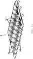
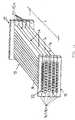
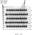
1a eine perspektivische Ansicht von zwei versetzten übereinander angeordneten Hohlprofilen in Rohrform, die miteinander durch Laserschweißen stoffschlüssig verbunden sind,1b eine Draufsicht auf zwei Hohlprofilreihen nach1a ,1c eine perspektivische Darstellung des in Strömungsräumen zwischen den Hohlprofilreihen eingesetzten Strömungsleit- und Abstandsbleches,2a eine perspektivische Darstellung einer aus mehreren Hohlprofilreihen zusammengesetzten Adsorber- Baueinheit mit kopf- und fußseitigem Boden,2b den Aufbau des Bodens in einer Explosionsdarstellung,3 einen Schnitt in Seitenansicht einer im Innenraum eines rechteckigen Gehäusemantels eingesetzten Adsorber-Baueinheit mit zuführseitigem Verteilraum für das zu behandelnde Rohgas und abführseitigem Sammelraum für das Reingas und das Desorbat als Hohlprofiladsorber,4 ein Beispiel von Strömungsschikanen in der Wandung eines Strömungskanals in perspektivischer Darstellung,5a einen Schnitt in Seitenansicht einer im Innenraum eines zylindrischen Gehäusemantels eingesetzten Adsorber-Baueinheit mit zuführseitigem Verteilraum für das zu behandelnde Rohgas und abführseitigem Sammelraum für das Reingas und Desorbat,5b eine Seitenansicht eines Hohlprofiladsorber4s aus beispielsweise zwei übereinander angeordneten Baueinheiten,6 eine schematische Darstellung des erfindungsgemäßen Hohlprofiladsorbers während der Adsortptionsphase mit gleichzeitigem Kühlen des Adsorptionsmittels in den Strömungskanälen und7 eine schematische Darstellung des erfindungsgemäßen Hohlprofiladsorbers während der Regenerationsphase mit gleichzeitigem Erwärmen des beladenen Adsorptionsmittels in den Strömungskanälen.
1a a perspective view of two staggered hollow profiles in tubular form, arranged one above the other, which are firmly connected to one another by laser welding,1b a plan view of two rows ofhollow profiles 1a ,1c a perspective view of the flow guide and spacer plates used in flow spaces between the rows of hollow profiles,2a a perspective view of an adsorber unit composed of several rows of hollow profiles with a base at the top and bottom,2 B the structure of the floor in an exploded view,3 a section in side view of an adsorber module inserted in the interior of a rectangular housing jacket with a supply-side distribution space for the raw gas to be treated and a discharge-side collection space for the pure gas and the desorbate as a hollow profile adsorber,4th an example of flow chicanes in the wall of a flow channel in a perspective view,5a a section in side view of an adsorber module inserted in the interior of a cylindrical housing jacket with a supply-side distribution space for the raw gas to be treated and a discharge-side collection space for the pure gas and desorbate,5b a side view of a hollow profile adsorber4s from, for example, two structural units arranged one above the other,6th a schematic representation of the hollow profile adsorber according to the invention during the adsorption phase with simultaneous cooling of the adsorbent in the flow channels and7th a schematic representation of the hollow profile adsorber according to the invention during the regeneration phase with simultaneous heating of the loaded adsorbent in the flow channels.
Die
Die Hohlprofile
Die mit ihren Rohrachsen
Übereinander angeordnete Hohlprofilreihen
The hollow profiles
The ones with their pipe axes
Rows of hollow profiles arranged one above the other
Zwischen den Hohlprofilreihen
Nach
Die
Die Böden
Die Zufuhr des Rohgases
The
The supply of the raw gas
Die
Der fußseitige Boden
Der zuströmseitige Verteilraum
The bottom at the foot
The
Die Hohlprofile
Zu- und abströmseitig sind die Hohlprofile
Das körnige Adsorptionsmittel
Die Strömungskanäle
The inflow and outflow sides are the hollow profiles
The granular adsorbent
The
Es ist bekannt, dass schlanke Kolonnen mit einem Verhältnis aus Schütt- und Partikeldurchmesser <20 zur Randgängigkeit neigen (
Um der Randgängigkeit entgegenzuwirken, besitzen die Strömungskanäle
Die Strömungsschikanen
In order to counteract the marginal accessibility, the flow channels have
The flow chicanes
Die im Innenraum des Gehäuses
Benachbarte Hohlprofilreihen
Adjacent rows of hollow profiles
Nach
Der Verteilraum
Zwei senkrecht übereinander angeordnete Adsorber-Baueinheiten
Die Verteilräume
Die Anzahl der Baueinheiten lässt sich somit auf die Menge des zu behandelnden Gases problemlos anpassen.To
The
Two adsorber units arranged vertically one above the other
The
The number of structural units can thus be easily adapted to the amount of gas to be treated.
Das Rohgas
Nachfolgend wird das erfindungsgemäße Verfahren mit zwei Hohlprofiladsorbern
Die
The
Die beiden Verteilräume
Im Verteilraum
Der Steuereinheit
Der Strom des Rohgases
In the
The
The flow of the raw gas
Von der Abführleitung
Die beiden Zuführleitungen
The two
Von den Sammelräumen
Reingas
Die Absperrarmaturen
Clean gas
The shut-off
Über den Verteilräumen
Zum Zuführen eines Heizmediums
Die Stromrichtung des Heizmediums
The direction of flow of the heating medium
Die Verbindungsleitung
In die Abführleitung
In the
Die Verbindungsleitungen
Von der Desorbatleitung
From the
Die Druckseite der Vakuumpumpe
Während der Adsorption ist die dem Verteilraum
Die zur Kühlung
Das Rohgas
Die Schad- und/oder Nutzkomponenten im Rohgas
Die während der Adsorption der Schad- und/oder Nutzkomponenten entstehende Adsorptionswärme wird durch das im Kreuzstrom zu den Strömungskanälen
The one for cooling
The raw gas
The harmful and / or useful components in the raw gas
The adsorption heat generated during the adsorption of the harmful and / or useful components is transferred to the flow channels in the cross-flow
Es wird jetzt auf die
Beim Desorptionsvorgang ist die Absperrarmatur
Ein Teilstrom des Reingases
Bei gleichzeitig geöffneter Absperrarmatur
Das in Strömungskanälen befindliche, mit der Schad- und/oder Nutzkomponente gesättigte Adsorptionsmittel wird soweit aufgeheizt bis die Schad- und/oder Nutzkomponente desorbiert. Die Desorptionstemperatur ist abhängig vom eingeregelten Absolutdruck und den Stoffeigenschaften der zu entfernenden Schad- und/oder Nutzkomponente.
Mit den im Verteilraum
Das Einregeln des Desorptionsdruckes
Das Desorbat
Die Kondensation der Schad- und/oder Nutzkomponente wird so vorgenommen, dass der Rückgasdruck
The shut-off valve is during the
A partial flow of the clean gas
With the shut-off valve open at the same time
The adsorbent located in flow channels and saturated with the harmful and / or useful component is heated until the harmful and / or useful component is desorbed. The desorption temperature depends on the regulated absolute pressure and the material properties of the harmful and / or useful component to be removed.
With the ones in the
Adjusting the desorption pressure
The desorbate
The condensation of the harmful and / or useful component is carried out in such a way that the return gas pressure
Sobald mit dem im Sammelraum
Die zur Kühlung
The one for cooling
Diese Verfahrensweise hat den besonderen Vorteil, dass einerseits das Spülgas
Ein weiterer Vorteil besteht darin, dass die Desorption bei einem Absolutdruck, beispielsweise bei 0,9 bara, und die Kondensation unter Druck, beispielsweise 1,0 barü, durchgeführt werden kann.
Der Unterdruck in den Strömungskanälen
All dies führt dazu, dass die Verlustenergie reduziert, die Zykluszeiten verkürzt, die Apparate verkleinert, Betriebskosten gesenkt und Investitionskosten eingespart werden können.This procedure has the particular advantage that, on the one hand, the flushing gas
Another advantage is that the desorption can be carried out at an absolute pressure, for example 0.9 bara, and the condensation can be carried out under pressure, for example 1.0 barg.
The negative pressure in the
All of this means that the loss of energy can be reduced, the cycle times shortened, the equipment downsized, operating costs reduced and investment costs saved.
Das erfindungsgemäße Verfahren soll nachfolgend an zwei Beispielen näher erläutert werden.The process according to the invention will be explained in more detail below using two examples.
Beispiel AExample A.
Ein Lösemittel verarbeitender Betrieb hat eine Abluftreinigungsanlage, um Lösungsmittel, die beispielsweise bei der Beschichtung von Folien verwendet werden, zu entfernen und die Abluft entsprechend zu reinigen. Außerdem können freie Emissionen in der Produktionshalle auftreten, die mit Absaugeinrichtungen zur Abluftreinigungsanlage geführt werden, um Einhaltung der maximalen Arbeitsplatzkonzentration in der Halle zu garantieren.
Diese aus der Produktionshalle anfallende Abluft soll mit dem erfindungsgemäßen Verfahren gereinigt bzw. behandelt werden.
Folgende Betriebsdaten liegen zugrunde:
- Desorptionsdruck pD: < 100 mbar
- Kondensations-Überdruck pK: min. 5,0 bar
- Adsorptionsmittel: ca. 65 kg Aktivkohle, 1,0
bis 4,0 mm - Länge der Strömungskanäle: 1.000 mm
- Lichte Weite der Strömungskanäle: 20 mm
- Adsorption
- Abluftmenge: 800 Nm3/h
- Adsorptionsdruck pAD (Betriebsdruck): 5,0 bar
- Eintrittstemperatur: 75°C nach Verdichtung
- Schadstoff in der Abluft: Aceton
- Schadstoffkonzentration am Eintritt: 350 mg/m3
- Schadstoffkonzentration am Austritt: < 50,0 mg/m3
- Temperaturerhöhung durch Adsorption: ca. 1,0°C
- Kühlmedium:
Kühlwasser mit 25,0°C - Temperatur im Adsorber (Baueinheit): 28,0°C
- Dauer der Adsorption: ca. 60 Minuten
- Regeneration
- Heizmedium: Heißwasser, 90°C
- Desorptionsdruck pD: < 100 mbar
- Desorptionstemperatur: ca. 85°C
- Benötigte Desorptionsenergie: ca. 7,5 kW
- Spülgas: Teilstrom des Reingases (gereinigte Abluft)
- Kondensationsdruck pK: 5,0 bar
- Kondensationstemperatur: ca. 25°C
- Regenerationsdauer: 40 Minuten
- Kühlung: 15 Minuten
This exhaust air from the production hall is to be cleaned or treated with the method according to the invention.
The following operating data are based on:
- Desorptionpressure p D : <100 mbar
- Condensation overpressure pK : min.5.0 bar
- Adsorbent: approx. 65 kg activated carbon, 1.0 to 4.0 mm
- Length of the flow channels: 1,000 mm
- Clear width of the flow channels: 20 mm
- adsorption
- Exhaust air volume: 800 Nm3 / h
- Adsorptionpressure p AD (operating pressure): 5.0 bar
- Inlet temperature: 75 ° C after compression
- Pollutant in the exhaust air: acetone
- Pollutant concentration at the inlet: 350 mg / m3
- Pollutant concentration at the outlet: <50.0 mg / m3
- Increase in temperature through adsorption: approx. 1.0 ° C
- Cooling medium: cooling water at 25.0 ° C
- Temperature in the adsorber (unit): 28.0 ° C
- Adsorption duration: approx. 60 minutes
- regeneration
- Heating medium: hot water, 90 ° C
- Desorptionpressure p D : <100 mbar
- Desorption temperature: approx. 85 ° C
- Desorption energy required: approx. 7.5 kW
- Purge gas: Partial flow of the pure gas (cleaned exhaust air)
- Condensationpressure p K : 5.0 bar
- Condensation temperature: approx. 25 ° C
- Regeneration time: 40 minutes
- Cooling: 15 minutes
Im vorliegenden Beispiel A läuft das erfindungsgemäße Verfahren wie folgt ab. Die unbehandelte Abluft mit einer geringen Schadstoffkonzentration von 350 mg/m3 Aceton wird als Rohgas
Der Hohlprofiladsorber
Als Adsorptionsmittel kommt Aktivkohle mit einer Partikelgröße 1,0 bis 4 mm mm zum Einsatz, die in die Strömungskanäle
Bei der Adsorption wird die in den Strömungskanälen
Activated carbon with a particle size of 1.0 to 4 mm is used as the adsorbent, which enters the
During adsorption, it is in the
Ähnlich wie im Beispiel A beschrieben, kann auch Abluft mit anderen Lösemitteln, beispielsweise Benzin, Toluol, Dichlormethan, Ethanol um nur einige gängige Schadstoffe zu nennen, in ähnlicher Form aufbereitet werden.
Die mit dem erfindungsgemäßen Verfahren erreichten Restkonzentrationen entsprechen den derzeitigen gesetzlichen Forderungen, z.B. bei 20 mg/m3 oder 50 mg/m3. Durch direkten Wärmeaustausch ist es möglich, das Spülgas
The residual concentrations achieved with the method according to the invention correspond to the current legal requirements, for example at 20 mg / m3 or 50 mg / m3 . By direct heat exchange it is possible to use the purge gas
Beispiel BExample B.
In einer kleinen Erdgasverflüssigungsanlage sollen pro Tag 30 Tonnen verflüssigtes Erdgas (LNG) hergestellt werden. Das im Pipeline-Erdgas enthaltene CO2 muss vor der Verflüssigung auf einen Wert unterhalb von 50 ppmv reduziert werden. Die zur Regeneration benötigte Menge an Spülgas
Folgende Betriebsdaten liegen zugrunde:
- Länge der Strömungskanäle: 1.500 mm
- Lichte Weite der Strömungskanäle: 20 mm
- Adsorption
- Benötigter Erdgasdurchsatz: 1.800 Nm3
- Durchsatz pro Hohlprofiladsorber: 600 Nm3/h
- Benötigte Anzahl Hohlprofiladsorber: 3
- CO2-Fracht: 18 kg/h
Adsorptionsdruck p AD: 50 bar- Adsorptionsmittel:
Molekularsieb bis - Geforderte Austrittskonzentration: < 50 ppmv CO2
- Dauer der Adsorption: ca. 120 Minuten
- Regeneration
- Heizmedium: Heißwasser, 95°C
- Desorptionsdruck pD: < 100 mbar
- Regenerationsdauer: 60 Minuten
- Spülgas: Reingas (gereinigtes Erdgas)
- Kühlmedium:
Kühlwasser mit 25°C - Kühlung: 45 Minuten
- Length of the flow channels: 1,500 mm
- Clear width of the flow channels: 20 mm
- adsorption
- Required natural gas throughput: 1,800 Nm3
- Throughput per hollow profile adsorber: 600 Nm3 / h
- Required number of hollow profile adsorbers: 3
- CO2 load: 18 kg / h
Adsorption pressure p AD: 50 bar- Adsorbent: molecular sieve 5A, 1.6 to 2.5 mm
- Required outlet concentration: <50 ppmv CO2
- Adsorption duration: approx. 120 minutes
- regeneration
- Heating medium: hot water, 95 ° C
- Desorptionpressure p D : <100 mbar
- Regeneration time: 60 minutes
- Purge gas: clean gas (purified natural gas)
- Cooling medium: cooling water at 25 ° C
- Cooling: 45 minutes
Das erfindungsgemäße Verfahren wird wie im Beispiel A beschrieben durchgeführt. Da das Pipeline-Erdgas unter Druck steht, kann jedoch auf die Kompression durch einen Verdichter verzichtet und das Rohgas
BezugszeichenlisteList of reference symbols
- 11
- Adsorber-BaueinheitAdsorber assembly
- 1a, 1b1a, 1b
- HohlprofiladsorberHollow profile adsorber
- 22
- Gehäusecasing
- 2a2a
- Gehäusemantel von
1a ,1b Housing jacket from1a ,1b - 3a, 3b3a, 3b
- zuströmseitiger Verteilraum von
1a ,1b Inflow-side distribution space from1a ,1b - 44th
- Zuführleitung für Rohgas
G Feed line for raw gasG - 5a, 5b5a, 5b
- Abströmseitiger Sammelraum von
1a ,1b Downstream collecting space from1a ,1b - 66th
- Abführleitung für Reingas
RG Discharge line for clean gasRG - 77th
- HohlprofilanordnungHollow profile arrangement
- 88th
- HohlprofileHollow profiles
- 99
- Strömungsleit- und AbstandsblechFlow guide and spacer plate
- 1010
- HohlprofilreiheHollow profile series
- 1111
- VersatzOffset
- 1212th
- Abstandshalterprofile in
9 Spacer profiles in9 - 1313th
- Wandung von
2 Wall of2 - 1414th
- StrömungsräumeFlow spaces
- 1515th
- Verteilraum für Kühl- bzw. HeizmediumDistribution space for cooling or heating medium
- 1616
- Kopfseitiger Boden von
1 Head-side bottom of1 - 16.1-16.n16.1-16.n
- Formteile von
16 Moldings from16 - 1717th
- Fußseitiger Boden von
1 Bottom floor of1 - 17.1-17.n17.1-17.n
- Formteile von
17 Moldings from17th - 1818th
- Kopfteil von
1a ,1b Headboard of1a ,1b - 1919th
- Fußteil von
1a ,1b Foot part of1a ,1b - 2020th
- Lücke in
WB Gap inWB - 2121
- StrömungskanäleFlow channels
- 2222nd
- SiebSieve
- 2323
- Gebläse, VerdichterBlower, compressor
- 2424
- StrömungsschikanenFlow chicanes
- 2525th
- Wandung von
8 Wall of8th - 2626th
- AusprägungExpression
- 27a27a
- Verbindungsleitung zu
3a Connecting line to3a - 27b27b
- Verbindungsleitung zu
3b Connecting line to3b - 2828
- Absperrarmatur in
27a Shut-off valve in27a - 2929
- Absperrarmatur in
27b Shut-off valve in27b - 3030th
- Drucksensor in
3a ,3b Pressure sensor in3a ,3b - 3131
- SteuerleitungControl line
- 3232
- SteuereinheitControl unit
- 3333
- Drucksensor in
5a ,5b Pressure sensor in5a ,5b - 3434
- Druckregelventil in
39a ,39b Pressure control valve in39a ,39b - 3535
- Spülgasleitung für Spülgas
SG Purge gas line for purge gasSG - 36a36a
- Zuführleitung von
SG in3a Feed line fromSG in3a - 36b36b
- Zuführleitung von
SG in3a Feed line fromSG in3a - 3737
- Regelventil in
36a für den Zufluss anSG Control valve in36a for the inflowSG - 3838
- Regelventil in
36b für den Zufluss anSG Control valve in36b for the inflowSG - 39a39a
- Verbindungsleitung von
5a zu6 für ReingasRG Connecting line from5a to6th for clean gasRG - 39b39b
- Verbindungsleitung von
5b zu6 für ReingasRG Connecting line from5b to6th for clean gasRG - 4040
- Absperrarmatur in
39a Shut-off valve in39a - 4141
- Absperrarmatur in
39b Shut-off valve in39b - 4242
- Zuflussseitige Verbindungsleitung für KühlmediumConnection line for cooling medium on the inflow side
- 43a43a
- Absperrarmatur in
44a Shut-off valve in44a - 43b43b
- Absperrarmatur in
44b Shut-off valve in44b - 44a44a
- Abführleitung für Kühlmedium von
1a Discharge line for cooling medium from1a - 44b44b
- Abführleitung für Kühlmedium von
1b Discharge line for cooling medium from1b - 4545
- Absperrarmatur in
47 für Heizmedium zu1a Shut-off valve in47 for heating medium too1a - 4646
- Absperrarmatur in
47 für Heizmedium zu1b Shut-off valve in47 for heating medium to1b - 4747
- Zuflußseitige Verbindungsleitung für HeizmediumConnection line on the inflow side for heating medium
- 4848
- Zuführleitung für KühlmediumSupply line for cooling medium
- 4949
- Zuführleitung für HeizmediumFeed line for heating medium
- 5050
- Absperrarmatur in
42 für Kühlmedium zu1a Shut-off valve in42 for cooling medium too1a - 5151
- Absperrarmatur in
42 für Kühlmedium zu1b Shut-off valve in42 for cooling medium too1b - 52a52a
- Absperrarmatur in
54a für Kondensat von1a Shut-off valve in54a for condensate from1a - 53a53a
- Absperrarmatur in
54a für Heizmedium von1a Shut-off valve in54a for heating medium from1a - 54a54a
- Abführleitung für Kondensat/Heizmedium von
1a Discharge line for condensate / heating medium from1a - 54b54b
- Abführleitung für Kondensat/Heizmedium von
1b Discharge line for condensate / heating medium from1b - 55a55a
- Absperrarmatur in
54b für Heizmedium von1b Shut-off valve in54b for heating medium from1b - 55b55b
- Absperrarmatur in
54b für Kondensat von1b Shut-off valve in54b for condensate from1b - 5656
- DesorbatleitungDesorbate line
- 5757
- Absperrarmatur in
56 für1a Shut-off valve in56 For1a - 5858
- Absperrarmatur in
56 für1b Shut-off valve in56 For1b - 5959
- Abführleitung für Desorbat
DS Drain line for desorbateDS - 6060
- VakuumpumpeVacuum pump
- 6161
- Wärmeaustauscher/KondensatorHeat exchanger / condenser
- 6262
- KondensatablassCondensate drain
- 6363
- RückgasleitungReturn gas line
- 6464
- Druckregelventil in
63 Pressure control valve in63 - 6565
- GassensorenGas sensors
- 6666
- DrucksensorPressure sensor
- AMAT THE
- AdsorptionsmittelAdsorbent
- ASAS
- Senkrechte Achse zu
RA Vertical axis tooRA - DSDS
- DesorbatDesorbate
- GG
- RohgasRaw gas
- GAGA
- Achse des Gehäusemantels
2 Axis of thecasing shell 2 - GRGR
- RückgasReturn gas
- HH
- Heizung/Heizmedium, KondensatHeating / heating medium, condensate
- KK
- Kühlung/KühlmediumCooling / cooling medium
- LRLR
- Längsrichtung von
10 Lengthwise from10 - RARA
- RohrachsePipe axis
- pADpAD
- AdsorptionsdruckAdsorption pressure
- pDpD
- DesorptionsdruckDesorption pressure
- pDSpDS
- DesorbatdruckDesorbate pressure
- pGpG
- Druck des Rohgases
G Pressure of the raw gasG - pGRpGR
- Druck des Rückgases
GR Pressure of the return gasGR - pKpK
- Kondensations-ÜberdruckCondensation overpressure
- pRGpRG
- Druck des ReingasesClean gas pressure
- pSGpSG
- Druck des SpülgasesPressure of the purge gas
- pVpV
- Saugseitiger Druck der VakuumpumpePressure on the suction side of the vacuum pump
- RGRG
- ReingasClean gas
- SS.
- StoßPush
- SFSF
- Strömungspfade von
K bzw.H Flow paths fromK or.H - SGSG
- SpülgasPurge gas
- SRRSRR
- Strömungsrichtung der Teilströme
TG des RohgasesDirection of flow of the partial flowsTG of the raw gas - SVSV
- Schweißverbindung im StoßWelded connection in the joint
- TGTG
- Teilströme des Rohgases
G Partial flows of the raw gasG - TSTS
- Teilströme des Spülgases
SG Partial flows of the purge gasSG - WW.
- Lichte Weite von
21 Clear width of21 - WBWB
- Wellenberge von
9 Crests of waves from9
ZITATE ENTHALTEN IN DER BESCHREIBUNGQUOTES INCLUDED IN THE DESCRIPTION
Diese Liste der vom Anmelder aufgeführten Dokumente wurde automatisiert erzeugt und ist ausschließlich zur besseren Information des Lesers aufgenommen. Die Liste ist nicht Bestandteil der deutschen Patent- bzw. Gebrauchsmusteranmeldung. Das DPMA übernimmt keinerlei Haftung für etwaige Fehler oder Auslassungen.This list of the documents listed by the applicant was generated automatically and is included solely for the better information of the reader. The list is not part of the German patent or utility model application. The DPMA assumes no liability for any errors or omissions.
Zitierte PatentliteraturPatent literature cited
- DE 3505351 A1 [0003]DE 3505351 A1 [0003]
- DE 19754185 C1 [0003]DE 19754185 C1 [0003]
- DE 19809200 A1 [0003, 0008]DE 19809200 A1 [0003, 0008]
- DE 10361515 A1 [0003]DE 10361515 A1 [0003]
- EP 2718086 B1 [0003]EP 2718086 B1 [0003]
- EP 1284813 B1 [0003]EP 1284813 B1 [0003]
- DE 60317545 A2 [0003]DE 60317545 A2 [0003]
- DE 1272891 B [0005]DE 1272891 B [0005]
- DE 3729517 A1 [0007]DE 3729517 A1 [0007]
- EP 1975539 A2 [0010]EP 1975539 A2 [0010]
- EP 1195193 B1 [0011]EP 1195193 B1 [0011]
- EP 1361919 B1 [0011]EP 1361919 B1 [0011]
- EP 1430265 B1 [0011]EP 1430265 B1 [0011]
- DE 112006000447 T5 [0011]DE 112006000447 T5 [0011]
- EP 1434652 B1 [0011]EP 1434652 B1 [0011]
- WO 03/095924 A1 [0011]WO 03/095924 A1 [0011]
- WO 2006/075163 A2 [0011]WO 2006/075163 A2 [0011]
Zitierte Nicht-PatentliteraturNon-patent literature cited
- K. Salem, Dissertation „Instationäre Temperatur- und Konzentrationsfelder in hochbelasteten Festbettadsorbern“, Cuvillier-Verlag Göttingen, 2006 [0043]K. Salem, dissertation “Unsteady temperature and concentration fields in highly loaded fixed bed adsorbers”, Cuvillier-Verlag Göttingen, 2006 [0043]
- BAKER ET AL („The Course of Liquor Flow in Packed Towers“, Trans AIChE 31(1935), S. 296-315 [0043]BAKER ET AL ("The Course of Liquor Flow in Packed Towers", Trans AIChE 31 (1935), pp. 296-315 [0043]
Claims (31)
Translated fromGermanPriority Applications (1)
| Application Number | Priority Date | Filing Date | Title |
|---|---|---|---|
| PCT/DE2020/000305WO2021121452A1 (en) | 2019-12-17 | 2020-12-04 | Method and hollow-profile adsorber for treating a gas laden with harmful and/or useful components |
Applications Claiming Priority (2)
| Application Number | Priority Date | Filing Date | Title |
|---|---|---|---|
| DE102019008705 | 2019-12-17 | ||
| DE102019008705.4 | 2019-12-17 |
Publications (1)
| Publication Number | Publication Date |
|---|---|
| DE102020007212A1true DE102020007212A1 (en) | 2021-07-01 |
Family
ID=76085297
Family Applications (4)
| Application Number | Title | Priority Date | Filing Date |
|---|---|---|---|
| DE102020007212.7AWithdrawnDE102020007212A1 (en) | 2019-12-17 | 2020-11-25 | Method and hollow profile adsorber for treating a gas contaminated with harmful and / or useful components |
| DE102020007213.5AWithdrawnDE102020007213A1 (en) | 2019-12-17 | 2020-11-25 | Method and device for treating a gas contaminated with harmful and / or useful components |
| DE102020007214.3AWithdrawnDE102020007214A1 (en) | 2019-12-17 | 2020-11-25 | Process and reactor for exothermic reactions in the gas phase |
| DE102020007211.9AWithdrawnDE102020007211A1 (en) | 2019-12-17 | 2020-11-25 | Adsorption refrigeration device and method for generating adsorption refrigeration from heat |
Family Applications After (3)
| Application Number | Title | Priority Date | Filing Date |
|---|---|---|---|
| DE102020007213.5AWithdrawnDE102020007213A1 (en) | 2019-12-17 | 2020-11-25 | Method and device for treating a gas contaminated with harmful and / or useful components |
| DE102020007214.3AWithdrawnDE102020007214A1 (en) | 2019-12-17 | 2020-11-25 | Process and reactor for exothermic reactions in the gas phase |
| DE102020007211.9AWithdrawnDE102020007211A1 (en) | 2019-12-17 | 2020-11-25 | Adsorption refrigeration device and method for generating adsorption refrigeration from heat |
Country Status (2)
| Country | Link |
|---|---|
| DE (4) | DE102020007212A1 (en) |
| WO (4) | WO2021121452A1 (en) |
Families Citing this family (7)
| Publication number | Priority date | Publication date | Assignee | Title |
|---|---|---|---|---|
| CN114042363B (en)* | 2021-10-28 | 2024-04-09 | 西安建筑科技大学 | Adsorption tower and method for inhibiting spontaneous combustion of desulfurization and denitrification active carbon |
| DE102022000431A1 (en) | 2022-01-26 | 2023-07-27 | Apodis Gmbh | Fuel cell system for a fuel cell vehicle |
| DE102022000430A1 (en) | 2022-01-26 | 2023-07-27 | Apodis Gmbh | Fuel cell system for a fuel cell vehicle |
| CN115871198A (en)* | 2022-12-27 | 2023-03-31 | 广东联塑机器制造有限公司 | A polyolefin cooling device |
| CN116589115B (en)* | 2023-04-25 | 2024-05-31 | 山东岱岳制盐有限公司 | Deep well bittern water purifying treatment system |
| AU2025201465A1 (en)* | 2024-03-01 | 2025-09-18 | Sagentia Ltd. | Modular grooved contactor stacks for carbon dioxide removal |
| CN118743962B (en)* | 2024-07-24 | 2025-09-12 | 上海交通大学 | An electric heating integrated ammonia reforming hydrogen production system with waste heat utilization |
Family Cites Families (40)
| Publication number | Priority date | Publication date | Assignee | Title |
|---|---|---|---|---|
| NL266305A (en) | 1960-09-16 | 1900-01-01 | ||
| DE1601215B2 (en) | 1967-11-03 | 1971-11-18 | Linde Ag, 6200 Wiesbaden | PLATE HEAT EXCHANGER IN PARTICULAR AS NITROGEN GAS COOLER |
| GB1572737A (en) | 1977-01-17 | 1980-08-06 | Exxon France | Heat pump |
| DE3049889A1 (en) | 1979-09-20 | 1982-03-04 | Tech Ind Therm Cetiat Centre | REFRIGERATION PROCESS AND DEVICE |
| DE3318098A1 (en) | 1983-05-18 | 1984-11-22 | Linde Ag, 6200 Wiesbaden | A process and reactor for carrying out an endothermic or exothermic reaction |
| DE3411675A1 (en) | 1984-03-27 | 1985-10-10 | Josef Hubert 5203 Much Schick | DEVICE FOR EXCHANGING HEAT AND FUEL BETWEEN TWO OR MORE FLOWABLE MEDIA |
| DE3505351A1 (en) | 1985-02-15 | 1986-08-21 | Linde Ag, 6200 Wiesbaden | Adsorber unit or catalyst unit, and process for the adsorptive or catalytic treatment of a fluid stream |
| FR2590356B1 (en) | 1985-11-19 | 1989-06-02 | Jeumont Schneider | DEVICE FOR THE CONTINUOUS PRODUCTION OF HOT AND COLD |
| DE3710823A1 (en) | 1987-04-01 | 1988-10-13 | Bavaria Anlagenbau Gmbh | METHOD FOR PRODUCING WELDED PLATE HEAT EXCHANGERS, IN PARTICULAR CROSS-CURRENT PLATE HEAT EXCHANGERS |
| AU581825B1 (en) | 1987-08-28 | 1989-03-02 | Union Industry Co., Ltd | Adsorption refrigeration system |
| DE3729517A1 (en) | 1987-09-03 | 1989-03-16 | Siemens Ag | ADSORPTION DEVICE FOR GAS SEPARATION |
| US5441716A (en)* | 1989-03-08 | 1995-08-15 | Rocky Research | Method and apparatus for achieving high reaction rates |
| DE4132015A1 (en) | 1991-09-26 | 1993-04-01 | Basf Ag | THERMOPLASTIC POLYURETHANE ELASTOMERS WITH A LOW ORGANIC CARBON DELIVERY VALUE, METHOD FOR THEIR PRODUCTION AND THEIR USE |
| DE19644938A1 (en) | 1996-10-29 | 1998-04-30 | Lutz Johannes | Adsorption chiller and method for its operation |
| DE19754185C1 (en) | 1997-12-06 | 1999-02-04 | Deg Engineering Gmbh | Chemical catalytic reactor assembly has cushion-like internal heat exchangers |
| DE19809200A1 (en) | 1998-03-04 | 1999-09-09 | Linde Ag | Flow-through apparatus and method for operating such an apparatus |
| DE19944426C2 (en)* | 1999-09-16 | 2003-01-09 | Balcke Duerr Energietech Gmbh | Plate heat exchangers and evaporators |
| EP1153653A1 (en) | 2000-05-11 | 2001-11-14 | Methanol Casale S.A. | Reactor for exothermic or endothermic heterogeneous reactions |
| DE10049194A1 (en) | 2000-10-05 | 2002-04-11 | Xcellsis Gmbh | Ractor structure in heat exchanger layer stack construction |
| GB2372462A (en) | 2001-02-21 | 2002-08-28 | Univ Newcastle | Reactor for conducting endothermic reactions |
| DE10108380A1 (en)* | 2001-02-21 | 2002-09-05 | Deg Intense Technologies & Ser | Reactor for carrying out catalyzed reactions |
| SE520006C2 (en) | 2001-09-20 | 2003-05-06 | Catator Ab | Device, method of manufacture and method of conducting catalytic reactions in plate heat exchangers |
| US7201883B2 (en) | 2001-10-12 | 2007-04-10 | Compactgtl Plc | Catalytic reactor |
| WO2003038363A2 (en) | 2001-10-29 | 2003-05-08 | Chart Heat Exchangers Lp | Heat exchangers |
| GB0210794D0 (en) | 2002-05-10 | 2002-06-19 | Chart Heat Exchangers Ltd | Heat exchangers |
| JP4212888B2 (en)* | 2002-12-26 | 2009-01-21 | 三菱化学エンジニアリング株式会社 | Plate type catalytic reactor |
| DE10361515A1 (en) | 2003-12-23 | 2005-07-28 | Basf Ag | Regulation of thermal chemical reaction by reference to inner temperature in presence of a particulate heterogenic particulate catalyst |
| EP1846717A2 (en)* | 2005-01-12 | 2007-10-24 | Chart Heat Exchangers Limited Partnership | Removable heat exchanger inserts |
| GB0504622D0 (en) | 2005-03-05 | 2005-04-13 | Accentus Plc | Catalytic reactors |
| DE102006011409B4 (en) | 2005-12-07 | 2008-02-28 | Sortech Ag | Adsorption machine with heat recovery |
| DE102006008786B4 (en)* | 2006-02-24 | 2008-01-17 | Fraunhofer-Gesellschaft zur Förderung der angewandten Forschung e.V. | Adsorption heat pump, adsorption chiller and adsorber elements contained therein based on an open-pore heat-conducting solid |
| DE202006014118U1 (en) | 2006-09-14 | 2006-11-16 | Krause, Roman | Tunnel awning system for viewing purposes and providing protection from the weather on balconies and for shops comprises an awning or tent material pulled onto a number of struts each having a rod and a pole |
| US7731782B2 (en)* | 2007-05-18 | 2010-06-08 | Exxonmobil Research And Engineering Company | Temperature swing adsorption of CO2 from flue gas utilizing heat from compression |
| DE102008053828A1 (en)* | 2008-10-30 | 2010-05-12 | Airbus Deutschland Gmbh | Improved adsorption cooling system and adsorption cooling process for an aircraft |
| US8936727B2 (en)* | 2009-03-06 | 2015-01-20 | Uop Llc | Multiple bed temperature controlled adsorption |
| KR102118074B1 (en) | 2011-06-07 | 2020-06-02 | 쓰리엠 이노베이티브 프로퍼티즈 캄파니 | System for adjusting position of slot die |
| EP3021962A1 (en) | 2013-07-19 | 2016-05-25 | InvenSor GmbH | Adsorption cooling machine having an adsorption agent, a method for generating cold, and the use of a dealuminised zeolite as adsorption agent in an adsorption cooling machine |
| PL3094928T3 (en) | 2014-01-10 | 2022-03-21 | Bry-Air (Asia) Pvt. Ltd. | Hybrid adsorber heat exchanging device and method of manufacture |
| JP6200911B2 (en)* | 2015-03-03 | 2017-09-20 | 株式会社豊田中央研究所 | HEAT PUMP AND CRYSTAL GENERATION METHOD |
| DE102015214374A1 (en) | 2015-07-29 | 2017-02-02 | Vaillant Gmbh | Adsorption heat pump with plate heat exchanger |
- 2020
- 2020-11-25DEDE102020007212.7Apatent/DE102020007212A1/ennot_activeWithdrawn
- 2020-11-25DEDE102020007213.5Apatent/DE102020007213A1/ennot_activeWithdrawn
- 2020-11-25DEDE102020007214.3Apatent/DE102020007214A1/ennot_activeWithdrawn
- 2020-11-25DEDE102020007211.9Apatent/DE102020007211A1/ennot_activeWithdrawn
- 2020-12-04WOPCT/DE2020/000305patent/WO2021121452A1/ennot_activeCeased
- 2020-12-04WOPCT/DE2020/000303patent/WO2021121450A1/ennot_activeCeased
- 2020-12-04WOPCT/DE2020/000304patent/WO2021121451A1/ennot_activeCeased
- 2020-12-04WOPCT/DE2020/000306patent/WO2021121453A1/ennot_activeCeased
Also Published As
| Publication number | Publication date |
|---|---|
| DE102020007211A1 (en) | 2021-06-17 |
| WO2021121453A1 (en) | 2021-06-24 |
| WO2021121452A1 (en) | 2021-06-24 |
| WO2021121451A1 (en) | 2021-06-24 |
| WO2021121450A1 (en) | 2021-06-24 |
| DE102020007213A1 (en) | 2021-06-17 |
| DE102020007214A1 (en) | 2021-07-01 |
Similar Documents
| Publication | Publication Date | Title |
|---|---|---|
| DE102020007212A1 (en) | Method and hollow profile adsorber for treating a gas contaminated with harmful and / or useful components | |
| EP0307581B1 (en) | Adsorption installation for gas separation | |
| DE69715748T2 (en) | Adsorption container with a radially flowed bed for vacuum pressure swing adsorption | |
| DE60318171T2 (en) | Device for the regeneration of adsorbents | |
| DE69410140T2 (en) | Gas purification process | |
| DE2461562B2 (en) | Gas adsorber vessel | |
| DE69213513T2 (en) | Process and device for gas separation | |
| EP0202516A2 (en) | Adsorption unit | |
| DE1272891B (en) | Process for cleaning gases or vapors | |
| DE1963773A1 (en) | Process for the separation of oxygen from air | |
| EP0449833A1 (en) | Process and device for separating undesirable constituents from waste gases | |
| DE102017001114A1 (en) | Apparatus and method for treating a polluted gas | |
| DE3430979A1 (en) | METHOD FOR THE AMMONIA SYNTHESIS | |
| DE102010014643A1 (en) | Tube bundle reactor, useful for catalytic gas phase reactions, comprises bundle of vertically arranged reaction tubes, a reactor shell, deflecting plate, reverse opening, bypass openings arranged in deflecting plate and adjusting device | |
| EP2361152A1 (en) | Method and device for regenerating bulk material that is loaded by adsorption and/or absorption | |
| DE3139369A1 (en) | ADSORPTION FILTER WITH DESORPTION DEVICE | |
| EP2365860B1 (en) | Pressure swing adsorption system and pressure swing adsorption method | |
| DE2548290A1 (en) | METHOD AND DEVICE FOR SEPARATING AIR | |
| EP0045929A1 (en) | Process and apparatus for the regeneration of an absorber | |
| DE4135018A1 (en) | Passing fluid over bed of catalyst or adsorbent - by dividing fluid into two for radial flow of fluids in reactor, for cleaning car exhaust, industrial effluent or processing etc. | |
| DE1794140C3 (en) | Continuous process for separating a gas mixture with the aid of an adsorbent | |
| WO2002083271A1 (en) | Washer and method for purifying gases | |
| DE19753409A1 (en) | Biofilter system | |
| DE1244720B (en) | Device for the adsorptive cleaning of gases, especially protective gas | |
| DE102006032609A1 (en) | Recovering halogenated hydrocarbons, especially inhalation anaesthetics from sorption filters, involves passing hot water vapour through a hydrophobic active carbon bed and then a hydrophobic zeolite bed |
Legal Events
| Date | Code | Title | Description |
|---|---|---|---|
| R012 | Request for examination validly filed | ||
| R082 | Change of representative | Representative=s name:COHAUSZ HANNIG BORKOWSKI WISSGOTT PATENTANWALT, DE | |
| R119 | Application deemed withdrawn, or ip right lapsed, due to non-payment of renewal fee |