DE102020003141A1 - Driver assistance system and method for coupling a trailer to a towing vehicle - Google Patents
Driver assistance system and method for coupling a trailer to a towing vehicleDownload PDFInfo
- Publication number
- DE102020003141A1 DE102020003141A1DE102020003141.2ADE102020003141ADE102020003141A1DE 102020003141 A1DE102020003141 A1DE 102020003141A1DE 102020003141 ADE102020003141 ADE 102020003141ADE 102020003141 A1DE102020003141 A1DE 102020003141A1
- Authority
- DE
- Germany
- Prior art keywords
- coupling
- towing
- video camera
- assistance system
- vehicle
- Prior art date
- Legal status (The legal status is an assumption and is not a legal conclusion. Google has not performed a legal analysis and makes no representation as to the accuracy of the status listed.)
- Withdrawn
Links
- 238000010168coupling processMethods0.000titleclaimsabstractdescription99
- 230000008878couplingEffects0.000titleclaimsabstractdescription98
- 238000005859coupling reactionMethods0.000titleclaimsabstractdescription98
- 238000000034methodMethods0.000titleclaimsdescription8
- 230000005855radiationEffects0.000claimsabstractdescription55
- 230000003068static effectEffects0.000claimsabstractdescription8
- 239000000725suspensionSubstances0.000claimsdescription12
- 238000013459approachMethods0.000claimsdescription9
- 230000005540biological transmissionEffects0.000claimsdescription2
- 230000001419dependent effectEffects0.000claimsdescription2
- 230000007423decreaseEffects0.000claims1
- 230000006378damageEffects0.000description4
- 238000009434installationMethods0.000description3
- BUHVIAUBTBOHAG-FOYDDCNASA-N(2r,3r,4s,5r)-2-[6-[[2-(3,5-dimethoxyphenyl)-2-(2-methylphenyl)ethyl]amino]purin-9-yl]-5-(hydroxymethyl)oxolane-3,4-diolChemical compoundCOC1=CC(OC)=CC(C(CNC=2C=3N=CN(C=3N=CN=2)[C@H]2[C@@H]([C@H](O)[C@@H](CO)O2)O)C=2C(=CC=CC=2)C)=C1BUHVIAUBTBOHAG-FOYDDCNASA-N0.000description1
- 208000011092Hand injuryDiseases0.000description1
- 238000005299abrasionMethods0.000description1
- 238000004140cleaningMethods0.000description1
- 239000004519greaseSubstances0.000description1
- 239000000314lubricantSubstances0.000description1
- 230000001050lubricating effectEffects0.000description1
- 238000012423maintenanceMethods0.000description1
- 230000009528severe injuryEffects0.000description1
Images


Classifications
- B—PERFORMING OPERATIONS; TRANSPORTING
- B60—VEHICLES IN GENERAL
- B60D—VEHICLE CONNECTIONS
- B60D1/00—Traction couplings; Hitches; Draw-gear; Towing devices
- B60D1/24—Traction couplings; Hitches; Draw-gear; Towing devices characterised by arrangements for particular functions
- B60D1/36—Traction couplings; Hitches; Draw-gear; Towing devices characterised by arrangements for particular functions for facilitating connection, e.g. hitch catchers, visual guide means, signalling aids
- B—PERFORMING OPERATIONS; TRANSPORTING
- B60—VEHICLES IN GENERAL
- B60R—VEHICLES, VEHICLE FITTINGS, OR VEHICLE PARTS, NOT OTHERWISE PROVIDED FOR
- B60R1/00—Optical viewing arrangements; Real-time viewing arrangements for drivers or passengers using optical image capturing systems, e.g. cameras or video systems specially adapted for use in or on vehicles
- B60R1/002—Optical viewing arrangements; Real-time viewing arrangements for drivers or passengers using optical image capturing systems, e.g. cameras or video systems specially adapted for use in or on vehicles specially adapted for covering the peripheral part of the vehicle, e.g. for viewing tyres, bumpers or the like
- B60R1/003—Optical viewing arrangements; Real-time viewing arrangements for drivers or passengers using optical image capturing systems, e.g. cameras or video systems specially adapted for use in or on vehicles specially adapted for covering the peripheral part of the vehicle, e.g. for viewing tyres, bumpers or the like for viewing trailer hitches
- B—PERFORMING OPERATIONS; TRANSPORTING
- B60—VEHICLES IN GENERAL
- B60D—VEHICLE CONNECTIONS
- B60D1/00—Traction couplings; Hitches; Draw-gear; Towing devices
- B60D1/01—Traction couplings or hitches characterised by their type
- B—PERFORMING OPERATIONS; TRANSPORTING
- B60—VEHICLES IN GENERAL
- B60D—VEHICLE CONNECTIONS
- B60D1/00—Traction couplings; Hitches; Draw-gear; Towing devices
- B60D1/58—Auxiliary devices
- B—PERFORMING OPERATIONS; TRANSPORTING
- B60—VEHICLES IN GENERAL
- B60G—VEHICLE SUSPENSION ARRANGEMENTS
- B60G17/00—Resilient suspensions having means for adjusting the spring or vibration-damper characteristics, for regulating the distance between a supporting surface and a sprung part of vehicle or for locking suspension during use to meet varying vehicular or surface conditions, e.g. due to speed or load
- B60G17/015—Resilient suspensions having means for adjusting the spring or vibration-damper characteristics, for regulating the distance between a supporting surface and a sprung part of vehicle or for locking suspension during use to meet varying vehicular or surface conditions, e.g. due to speed or load the regulating means comprising electric or electronic elements
- B60G17/0152—Resilient suspensions having means for adjusting the spring or vibration-damper characteristics, for regulating the distance between a supporting surface and a sprung part of vehicle or for locking suspension during use to meet varying vehicular or surface conditions, e.g. due to speed or load the regulating means comprising electric or electronic elements characterised by the action on a particular type of suspension unit
- B60G17/0155—Resilient suspensions having means for adjusting the spring or vibration-damper characteristics, for regulating the distance between a supporting surface and a sprung part of vehicle or for locking suspension during use to meet varying vehicular or surface conditions, e.g. due to speed or load the regulating means comprising electric or electronic elements characterised by the action on a particular type of suspension unit pneumatic unit
- B—PERFORMING OPERATIONS; TRANSPORTING
- B60—VEHICLES IN GENERAL
- B60R—VEHICLES, VEHICLE FITTINGS, OR VEHICLE PARTS, NOT OTHERWISE PROVIDED FOR
- B60R1/00—Optical viewing arrangements; Real-time viewing arrangements for drivers or passengers using optical image capturing systems, e.g. cameras or video systems specially adapted for use in or on vehicles
- B60R1/20—Real-time viewing arrangements for drivers or passengers using optical image capturing systems, e.g. cameras or video systems specially adapted for use in or on vehicles
- B60R1/22—Real-time viewing arrangements for drivers or passengers using optical image capturing systems, e.g. cameras or video systems specially adapted for use in or on vehicles for viewing an area outside the vehicle, e.g. the exterior of the vehicle
- B60R1/23—Real-time viewing arrangements for drivers or passengers using optical image capturing systems, e.g. cameras or video systems specially adapted for use in or on vehicles for viewing an area outside the vehicle, e.g. the exterior of the vehicle with a predetermined field of view
- B60R1/26—Real-time viewing arrangements for drivers or passengers using optical image capturing systems, e.g. cameras or video systems specially adapted for use in or on vehicles for viewing an area outside the vehicle, e.g. the exterior of the vehicle with a predetermined field of view to the rear of the vehicle
- B—PERFORMING OPERATIONS; TRANSPORTING
- B60—VEHICLES IN GENERAL
- B60W—CONJOINT CONTROL OF VEHICLE SUB-UNITS OF DIFFERENT TYPE OR DIFFERENT FUNCTION; CONTROL SYSTEMS SPECIALLY ADAPTED FOR HYBRID VEHICLES; ROAD VEHICLE DRIVE CONTROL SYSTEMS FOR PURPOSES NOT RELATED TO THE CONTROL OF A PARTICULAR SUB-UNIT
- B60W10/00—Conjoint control of vehicle sub-units of different type or different function
- B60W10/04—Conjoint control of vehicle sub-units of different type or different function including control of propulsion units
- B—PERFORMING OPERATIONS; TRANSPORTING
- B60—VEHICLES IN GENERAL
- B60W—CONJOINT CONTROL OF VEHICLE SUB-UNITS OF DIFFERENT TYPE OR DIFFERENT FUNCTION; CONTROL SYSTEMS SPECIALLY ADAPTED FOR HYBRID VEHICLES; ROAD VEHICLE DRIVE CONTROL SYSTEMS FOR PURPOSES NOT RELATED TO THE CONTROL OF A PARTICULAR SUB-UNIT
- B60W10/00—Conjoint control of vehicle sub-units of different type or different function
- B60W10/10—Conjoint control of vehicle sub-units of different type or different function including control of change-speed gearings
- B—PERFORMING OPERATIONS; TRANSPORTING
- B60—VEHICLES IN GENERAL
- B60W—CONJOINT CONTROL OF VEHICLE SUB-UNITS OF DIFFERENT TYPE OR DIFFERENT FUNCTION; CONTROL SYSTEMS SPECIALLY ADAPTED FOR HYBRID VEHICLES; ROAD VEHICLE DRIVE CONTROL SYSTEMS FOR PURPOSES NOT RELATED TO THE CONTROL OF A PARTICULAR SUB-UNIT
- B60W10/00—Conjoint control of vehicle sub-units of different type or different function
- B60W10/18—Conjoint control of vehicle sub-units of different type or different function including control of braking systems
- B—PERFORMING OPERATIONS; TRANSPORTING
- B60—VEHICLES IN GENERAL
- B60W—CONJOINT CONTROL OF VEHICLE SUB-UNITS OF DIFFERENT TYPE OR DIFFERENT FUNCTION; CONTROL SYSTEMS SPECIALLY ADAPTED FOR HYBRID VEHICLES; ROAD VEHICLE DRIVE CONTROL SYSTEMS FOR PURPOSES NOT RELATED TO THE CONTROL OF A PARTICULAR SUB-UNIT
- B60W10/00—Conjoint control of vehicle sub-units of different type or different function
- B60W10/22—Conjoint control of vehicle sub-units of different type or different function including control of suspension systems
- H—ELECTRICITY
- H04—ELECTRIC COMMUNICATION TECHNIQUE
- H04N—PICTORIAL COMMUNICATION, e.g. TELEVISION
- H04N7/00—Television systems
- H04N7/18—Closed-circuit television [CCTV] systems, i.e. systems in which the video signal is not broadcast
- B—PERFORMING OPERATIONS; TRANSPORTING
- B60—VEHICLES IN GENERAL
- B60G—VEHICLE SUSPENSION ARRANGEMENTS
- B60G2202/00—Indexing codes relating to the type of spring, damper or actuator
- B60G2202/10—Type of spring
- B60G2202/15—Fluid spring
- B60G2202/152—Pneumatic spring
- B—PERFORMING OPERATIONS; TRANSPORTING
- B60—VEHICLES IN GENERAL
- B60G—VEHICLE SUSPENSION ARRANGEMENTS
- B60G2500/00—Indexing codes relating to the regulated action or device
- B60G2500/30—Height or ground clearance
- B—PERFORMING OPERATIONS; TRANSPORTING
- B60—VEHICLES IN GENERAL
- B60R—VEHICLES, VEHICLE FITTINGS, OR VEHICLE PARTS, NOT OTHERWISE PROVIDED FOR
- B60R2300/00—Details of viewing arrangements using cameras and displays, specially adapted for use in a vehicle
- B60R2300/30—Details of viewing arrangements using cameras and displays, specially adapted for use in a vehicle characterised by the type of image processing
- B60R2300/304—Details of viewing arrangements using cameras and displays, specially adapted for use in a vehicle characterised by the type of image processing using merged images, e.g. merging camera image with stored images
- B60R2300/305—Details of viewing arrangements using cameras and displays, specially adapted for use in a vehicle characterised by the type of image processing using merged images, e.g. merging camera image with stored images merging camera image with lines or icons
- B—PERFORMING OPERATIONS; TRANSPORTING
- B60—VEHICLES IN GENERAL
- B60R—VEHICLES, VEHICLE FITTINGS, OR VEHICLE PARTS, NOT OTHERWISE PROVIDED FOR
- B60R2300/00—Details of viewing arrangements using cameras and displays, specially adapted for use in a vehicle
- B60R2300/80—Details of viewing arrangements using cameras and displays, specially adapted for use in a vehicle characterised by the intended use of the viewing arrangement
- B60R2300/808—Details of viewing arrangements using cameras and displays, specially adapted for use in a vehicle characterised by the intended use of the viewing arrangement for facilitating docking to a trailer
- B—PERFORMING OPERATIONS; TRANSPORTING
- B60—VEHICLES IN GENERAL
- B60R—VEHICLES, VEHICLE FITTINGS, OR VEHICLE PARTS, NOT OTHERWISE PROVIDED FOR
- B60R2300/00—Details of viewing arrangements using cameras and displays, specially adapted for use in a vehicle
- B60R2300/80—Details of viewing arrangements using cameras and displays, specially adapted for use in a vehicle characterised by the intended use of the viewing arrangement
- B60R2300/8086—Details of viewing arrangements using cameras and displays, specially adapted for use in a vehicle characterised by the intended use of the viewing arrangement for vehicle path indication
- B—PERFORMING OPERATIONS; TRANSPORTING
- B60—VEHICLES IN GENERAL
- B60W—CONJOINT CONTROL OF VEHICLE SUB-UNITS OF DIFFERENT TYPE OR DIFFERENT FUNCTION; CONTROL SYSTEMS SPECIALLY ADAPTED FOR HYBRID VEHICLES; ROAD VEHICLE DRIVE CONTROL SYSTEMS FOR PURPOSES NOT RELATED TO THE CONTROL OF A PARTICULAR SUB-UNIT
- B60W2420/00—Indexing codes relating to the type of sensors based on the principle of their operation
- B60W2420/40—Photo, light or radio wave sensitive means, e.g. infrared sensors
- B60W2420/403—Image sensing, e.g. optical camera
- B—PERFORMING OPERATIONS; TRANSPORTING
- B60—VEHICLES IN GENERAL
- B60W—CONJOINT CONTROL OF VEHICLE SUB-UNITS OF DIFFERENT TYPE OR DIFFERENT FUNCTION; CONTROL SYSTEMS SPECIALLY ADAPTED FOR HYBRID VEHICLES; ROAD VEHICLE DRIVE CONTROL SYSTEMS FOR PURPOSES NOT RELATED TO THE CONTROL OF A PARTICULAR SUB-UNIT
- B60W2540/00—Input parameters relating to occupants
- B60W2540/10—Accelerator pedal position
- B—PERFORMING OPERATIONS; TRANSPORTING
- B60—VEHICLES IN GENERAL
- B60W—CONJOINT CONTROL OF VEHICLE SUB-UNITS OF DIFFERENT TYPE OR DIFFERENT FUNCTION; CONTROL SYSTEMS SPECIALLY ADAPTED FOR HYBRID VEHICLES; ROAD VEHICLE DRIVE CONTROL SYSTEMS FOR PURPOSES NOT RELATED TO THE CONTROL OF A PARTICULAR SUB-UNIT
- B60W2710/00—Output or target parameters relating to a particular sub-units
- B60W2710/06—Combustion engines, Gas turbines
- B—PERFORMING OPERATIONS; TRANSPORTING
- B60—VEHICLES IN GENERAL
- B60W—CONJOINT CONTROL OF VEHICLE SUB-UNITS OF DIFFERENT TYPE OR DIFFERENT FUNCTION; CONTROL SYSTEMS SPECIALLY ADAPTED FOR HYBRID VEHICLES; ROAD VEHICLE DRIVE CONTROL SYSTEMS FOR PURPOSES NOT RELATED TO THE CONTROL OF A PARTICULAR SUB-UNIT
- B60W2710/00—Output or target parameters relating to a particular sub-units
- B60W2710/10—Change speed gearings
- B—PERFORMING OPERATIONS; TRANSPORTING
- B60—VEHICLES IN GENERAL
- B60W—CONJOINT CONTROL OF VEHICLE SUB-UNITS OF DIFFERENT TYPE OR DIFFERENT FUNCTION; CONTROL SYSTEMS SPECIALLY ADAPTED FOR HYBRID VEHICLES; ROAD VEHICLE DRIVE CONTROL SYSTEMS FOR PURPOSES NOT RELATED TO THE CONTROL OF A PARTICULAR SUB-UNIT
- B60W2710/00—Output or target parameters relating to a particular sub-units
- B60W2710/18—Braking system
- B—PERFORMING OPERATIONS; TRANSPORTING
- B60—VEHICLES IN GENERAL
- B60W—CONJOINT CONTROL OF VEHICLE SUB-UNITS OF DIFFERENT TYPE OR DIFFERENT FUNCTION; CONTROL SYSTEMS SPECIALLY ADAPTED FOR HYBRID VEHICLES; ROAD VEHICLE DRIVE CONTROL SYSTEMS FOR PURPOSES NOT RELATED TO THE CONTROL OF A PARTICULAR SUB-UNIT
- B60W2710/00—Output or target parameters relating to a particular sub-units
- B60W2710/22—Suspension systems
Landscapes
- Engineering & Computer Science (AREA)
- Mechanical Engineering (AREA)
- Multimedia (AREA)
- Transportation (AREA)
- Combustion & Propulsion (AREA)
- Chemical & Material Sciences (AREA)
- Signal Processing (AREA)
- Fittings On The Vehicle Exterior For Carrying Loads, And Devices For Holding Or Mounting Articles (AREA)
- Vehicle Body Suspensions (AREA)
- Control Of Driving Devices And Active Controlling Of Vehicle (AREA)
- Regulating Braking Force (AREA)
- Studio Devices (AREA)
- Length Measuring Devices By Optical Means (AREA)
Abstract
Translated fromGermanDescription
Translated fromGermanDie Erfindung betrifft ein Fahrerassistenzsystem zum Ankuppeln eines Anhängers an ein Zugfahrzeug entsprechend den im Oberbegriff des Anspruchs 1 stehenden Merkmalen. Darüber hinaus ist die Erfindung auch an einem entsprechenden Verfahren verwirklicht.The invention relates to a driver assistance system for coupling a trailer to a towing vehicle in accordance with the features in the preamble of claim 1. In addition, the invention is also implemented in a corresponding method.
Das Zugfahrzeug und der Anhänger bilden in gekuppeltem Zustand einen Gliederzug. Zum Ankuppeln des Anhängers fährt das Zugfahrzeug mit seiner Kupplung rückwärts an den stehenden Anhänger solange heran, bis eine an einer Deichsel des Anhängers ausgebildete Zugöse korrekt in ein Fangmaul der Kupplung eingefahren ist und darin mittels eines Kupplungsbolzens oder Verschlussbügels verriegelt wird. Besonders schwierig ist jedoch das Einschätzen der räumlichen Relativposition von Kupplung und Zugöse bei Gliederzügen mit Zentralachsanhängern, da bei den hierfür verwendeten Zugfahrzeugen die Kupplung sehr weit nach innen in Richtung der Fahrzeughinterachse des Zugfahrzeugs zurückversetzt ist.When coupled, the towing vehicle and the trailer form an articulated train. To couple the trailer, the towing vehicle with its coupling moves backwards to the stationary trailer until a towing eye formed on a drawbar of the trailer is correctly inserted into a catch of the coupling and locked therein by means of a coupling bolt or locking bracket. However, it is particularly difficult to assess the spatial relative position of the coupling and the towing eye in articulated trains with central axle trailers, since the towing vehicles used for this purpose have the coupling set back very far inwards in the direction of the rear axle of the towing vehicle.
Im Stand der Technik sind bereits Bemühungen unternommen worden, den Ankuppelvorgang eines Zugfahrzeugs und Anhängers durch ein Fahrerassistenzsystem für den Fahrer zu vereinfachen. Die
Die
Der Erfindung lag daher die Aufgabe zugrunde, ein Fahrerassistenzsystem bereitzustellen, mit dessen Hilfe der Fahrer während einer rückwärtigen Annäherung an einen Anhänger eine Abschätzung der dreidimensionalen Lage der Zugöse zu dem Zugfahrzeug vornehmen kann.The invention was therefore based on the object of providing a driver assistance system with the aid of which the driver can estimate the three-dimensional position of the towing eye in relation to the towing vehicle while approaching a trailer from behind.
Die Aufgabe wird erfindungsgemäß mit den Merkmalen der unabhängigen Ansprüche gelöst. Die Kupplung ist typischerweise eine Maulkupplung oder eine Hakenkupplung für Lastkraftwagen.The object is achieved according to the invention with the features of the independent claims. The coupling is typically a jaw coupling or a hook coupling for trucks.
Nach Anspruch 1 ist die Videokamera vertikal beabstandet zu der Kupplung angeordnet, woraus eine räumliche Tiefe im Videobild resultiert. Der vertikale Abstand zur Kupplung kann prinzipiell über der Kupplung oder unter der Kupplung realisiert sein, wobei eine Anbringung der Videokamera über der Kupplung im Hinblick auf die Einbausituation am Zugfahrzeug bevorzugt ist. Eine unter der Kupplung angebrachte Videokamera befindet sich häufig in einer exponierten Lage und ist dadurch einem erhöhten Risiko für Beschädigungen ausgesetzt.According to claim 1, the video camera is arranged at a vertical distance from the coupling, which results in a spatial depth in the video image. The vertical distance to the coupling can in principle be realized above the coupling or below the coupling, with the video camera being attached above the coupling in view of the installation situation on the towing vehicle being preferred. A video camera attached under the coupling is often in an exposed position and is therefore exposed to an increased risk of damage.
Die Strahlenkorridore sind als Overlay statisch zum Videobild der Videokamera angeordnet. Hierfür können die Strahlenkorridore fest auf einer Linse der Videokamera aufgebracht sein. Alternativ sind die Strahlenkorridore mit einer Bildverarbeitungssoftware der Videokamera im Videobild generiert oder als Overlay auf einen Bildsensor der Videokamera aufgebracht. In einer noch anderen Ausführungsform können die Strahlenkorridore über das Videobild der Anzeigevorrichtung gelegt sein.The radiation corridors are arranged statically as an overlay to the video image of the video camera. For this purpose, the radiation corridors can be fixed on a lens of the video camera. Alternatively, the radiation corridors are generated in the video image with image processing software of the video camera or applied as an overlay to an image sensor of the video camera. In yet another embodiment, the beam corridors can be laid over the video image of the display device.
Ausgehend von einer vorgegebenen Größe von Fangmaul und Bezugselement, insbesondere der Zugöse, sowie einer vorgegebenen Einbauposition und daraus resultierendem Neigungswinkel der Kamera wächst während der Annäherung die Größe des Bezugselementes im Videobild entsprechend dem Verlauf und der Größe der Strahlenkorridore. Die Strahlenkorridore sind insbesondere symmetrisch zur Fahrzeuglängsachse ausgerichtet.Based on a specified size of the jaw and reference element, in particular the towing eye, as well as a specified installation position and the resulting angle of inclination of the camera, the size of the reference element in the video image grows during the approach according to the course and size of the radiation corridors. The radiation corridors are in particular aligned symmetrically to the longitudinal axis of the vehicle.
Aufgrund des räumlichen Verlaufs der Strahlenkorridore kann die Position eines Bezugselementes des Anhängers, beispielsweise die Zugöse, sowohl hinsichtlich ihrer seitlichen Lage als auch bezüglich ihrer Höhenlage zu den Strahlenkorridoren abgeschätzt werden. Bei einer vertikalen Position der Videokamera über der Kupplung gilt: Je niedriger das Bezugselement angeordnet ist, desto weiter entfernt ist der Abstand zur Videokamera und desto kleiner erscheint dieses relativ zu den Strahlenkorridoren. Je höher das Bezugselement angeordnet ist, desto geringer ist der Abstand zur Videokamera und desto größer erscheint dieses relativ zu den Strahlenkorridoren. Aufgrund der zulaufenden Ausrichtung der Strahlenkorridore, wandert während der Annäherung des Zugfahrzeugs das Bezugselement, insbesondere der Außendurchmesser der Zugöse, in der Fahrzeuglängsachse relativ zu den Strahlenkorridoren, so dass sich auch ein Abstand in der Fahrzeuglängsachse vom Fahrer abschätzen lässt.Due to the spatial course of the radiation corridors, the position of a reference element of the trailer, for example the towing eye, can be estimated both in terms of its lateral position and in terms of its height relative to the radiation corridors. In the case of a vertical position of the video camera above the coupling, the following applies: the lower the reference element, the further away the distance from the video camera and the smaller it appears relative to the radiation corridors. The higher the reference element, the smaller the distance to the video camera and the larger it appears relative to the radiation corridors. Due to the converging alignment of the radiation corridors, it wanders during the approach of the towing vehicle, the reference element, in particular the outer diameter of the towing eye, in the vehicle's longitudinal axis relative to the radiation corridors, so that the driver can also estimate a distance in the vehicle's longitudinal axis.
Neben der räumlichen Abschätzung der Position des Bezugselementes, insbesondere der Zugöse, resultiert aus der vertikal versetzten Position der Videokamera zu der Kupplung noch ein Sicherheitsvorteil, da für eine Wartung oder Reinigung der Videokamera nicht in das Fangmaul der Kupplung hineingegriffen zu werden braucht. Dieses birgt insbesondere bei Maulkupplungen stets die Gefahr, dass sich ein federvorgespannter Kupplungsbolzen aus seiner Öffnungsstellung löst und in die Schließstellung vorschnellt, wodurch beispielsweise schwere Handverletzungen hervorgerufen werden können. Aufgrund des baulichen Abstandes der Videokamera zu der Kupplung unterliegt diese ohnehin einer geringeren Verschmutzung, da kein Schmierfett oder Abrieb des Fangmauls oder Kupplungsbolzens bis zu der Videokamera wandert und dort ablegt.In addition to the spatial estimation of the position of the reference element, in particular the towing eye, the vertically offset position of the video camera in relation to the coupling also results in a safety advantage, since maintenance or cleaning of the video camera does not require reaching into the coupling mouth. In particular in the case of jaw couplings, this always harbors the risk that a spring-loaded coupling bolt will loosen from its open position and snap forward into the closed position, which can cause serious hand injuries, for example. Due to the structural distance between the video camera and the coupling, it is subject to less soiling anyway, since no lubricating grease or abrasion of the catch mouth or coupling bolt migrates to the video camera and deposits it there.
Gemäß einer besonders bevorzugten Ausführungsform weisen die Strahlenkorridore jeweils eine Innenbegrenzungslinie sowie eine Außenbegrenzungslinie auf und für ein korrektes Ankuppeln während einer Annäherung von Fangmaul und Zugöse ist ein Bezugselement der Zugöse im Videobild zwischen der Innenbegrenzungslinie und der Außenbegrenzungslinie beider Strahlenkorridore angeordnet. Durch die Strahlenkorridore ist die Relativlage der Zugöse sowohl in seitlicher Richtung als auch in der Fahrzeuglängsachse abschätzbar. Die Innenbegrenzungslinie und Außenbegrenzungslinie definieren die Breite des zugehörigen Strahlenkorridors, aus welcher sich besonders gut eine Höheninformation der Kupplung relativ zu der Zugöse ableiten lässt.According to a particularly preferred embodiment, the radiation corridors each have an inner delimitation line and an outer delimitation line and a reference element of the towing eye is arranged in the video image between the inner delimitation line and the outer delimitation line of both radiation corridors for correct coupling when the catching mouth and towing eye are approaching. Thanks to the radiation corridors, the relative position of the towing eye can be estimated both in the lateral direction and in the vehicle's longitudinal axis. The inner delimitation line and outer delimitation line define the width of the associated radiation corridor, from which height information of the coupling relative to the towing eye can be derived particularly well.
Für den Fall, dass die Zugöse, insbesondere deren Außendurchmesser, über die Innenbegrenzungslinie und die Außenbegrenzungslinie beider Strahlenkorridore seitlich hinausragt, befindet sich die ortsfest zur Videokamera angeordnete Kupplung in einer zu niedrigen Lage. Die statischen und stets gleich großen Strahlenkorridore der Videokamera sind relativ zu nah an der Zugöse, so dass diese im Videobild verhältnismäßig groß ist und die Innenbegrenzungs- und Außenbegrenzungslinien überragt.In the event that the drawbar eye, in particular its outer diameter, protrudes laterally beyond the inner delimitation line and the outer delimitation line of both radiation corridors, the coupling, which is fixed to the video camera, is in a position that is too low. The static and always the same size beam corridors of the video camera are relatively too close to the towing eye, so that it is relatively large in the video image and protrudes beyond the inner and outer boundary lines.
Falls die Zugöse dagegen, insbesondere deren Außendurchmesser, innerhalb der Innenbegrenzungslinien beider Strahlenkorridore ausgerichtet ist, befindet sich die ortsfest zur Videokamera angeordnete Kupplung in einer zu hohen Lage. Die statischen und stets gleich großen Strahlenkorridore der Videokamera sind in vertikaler Richtung relativ zu weit beabstandet zu der Zugöse, so dass diese im Videobild verhältnismäßig klein ist und, insbesondere ihr Außendurchmesser, nicht einmal die Innenbegrenzungsbegrenzungslinien überragt.If, on the other hand, the drawbar eye, in particular its outer diameter, is aligned within the inner delimitation lines of both beam corridors, the coupling, which is fixedly arranged in relation to the video camera, is in a position that is too high. The static and always the same size beam corridors of the video camera are relatively too far apart in the vertical direction from the drawbar eye, so that this is relatively small in the video image and, in particular its outer diameter, does not even protrude beyond the inner boundary lines.
Vorteilhafterweise ist das Bezugselement ein Außendurchmesser der Zugöse. Hieraus resultiert der Vorteil, dass der Außendurchmesser besonders gut im Videobild auch bei diffusen Lichtverhältnissen sichtbar ist. Es wäre auch möglich, als Bezugselement des Anhängers einen Innendurchmesser der Zugöse heranzuziehen, dessen Sichtkanten jedoch weniger gut zu erkennen sind. Zusätzliche Schmierstoffanhaftungen verfälschen im Videobild eine Abschätzung der Position des Innendurchmessers bezüglich der Strahlenkorridore zusätzlich. Grundsätzlich wäre es auch denkbar, ein abseits der Deichsel ortsfest angeordnetes Bezugselement zu bestimmen und die Strahlenkorridore darauf zu skalieren. Sofern dieses entfernt von der Deichsel befindliche Bezugselement mit einem Offset versehen ist, wäre ebenfalls ein korrektes Einfahren der Zugöse in die Kupplung möglich, solange das Bezugselement zwischen der Innenbegrenzungslinie und Außenbegrenzungslinie beider Strahlenkorridore gehalten wird.The reference element is advantageously an outer diameter of the drawbar eye. This has the advantage that the outer diameter is particularly well visible in the video image, even in diffuse lighting conditions. It would also be possible to use an inside diameter of the towing eye as the reference element of the trailer, but the visible edges of the drawbar are less easy to see. Additional lubricant deposits also falsify an estimate of the position of the inside diameter in relation to the radiation corridors in the video image. In principle, it would also be conceivable to determine a reference element arranged in a stationary manner away from the drawbar and to scale the radiation corridors to it. If this reference element located at a distance from the drawbar is provided with an offset, correct retraction of the drawbar eye into the coupling would also be possible, as long as the reference element is held between the inner limit line and the outer limit line of both radiation corridors.
Ein Abstand zwischen der Innenbegrenzungslinie und der Außenbegrenzungslinie eines Strahlenkorridors kann insbesondere abhängig von einem Toleranzspielraum des Fangmauls und/oder der Zugöse sein. Der Toleranzspielraum der Kupplung gibt an, unter welcher Fehlstellung der Kupplung zu der Zugöse noch ein korrektes Ankuppeln möglich ist. Je größer der Toleranzspielraum des Fangmauls ist, desto größer kann auch der Abstand zwischen der Innenbegrenzungslinie und der Außenbegrenzungslinie eines Strahlenkorridors sein.A distance between the inner delimitation line and the outer delimitation line of a radiation corridor can in particular be dependent on a tolerance range of the catching mouth and / or the towing eye. The tolerance range of the coupling indicates the misalignment of the coupling to the towing eye under which correct coupling is still possible. The greater the margin of tolerance of the mouth, the greater the distance between the inner boundary line and the outer boundary line of a radiation corridor can be.
Vorzugsweise ist der Abstand mit zunehmender Distanz geringer, das heißt jeder der Strahlenkorridore verjüngt sich mit zunehmender Distanz in der Fahrzeuglängsachse.The distance is preferably smaller as the distance increases, that is to say each of the radiation corridors tapers in the longitudinal axis of the vehicle as the distance increases.
Zweckmäßigerweise ist die Videokamera in der Fahrzeuglängsachse angeordnet. Hieraus resultiert der Vorteil, dass die Videokamera mit der optimalen Ankuppelrichtung fluchtet und die statischen Strahlenkorridore symmetrisch zur Kupplung angeordnet sind, so dass auf eine Seitenkorrektur bei der Darstellung im Videobild verzichtet werden kann.The video camera is expediently arranged in the longitudinal axis of the vehicle. This has the advantage that the video camera is aligned with the optimal coupling direction and the static radiation corridors are arranged symmetrically to the coupling, so that there is no need to correct the side when displaying the video image.
Es kann außerdem sinnvoll sein, wenn das Fangmaul einen konisch aufgeweiteten Wandabschnitt aufweist und die Videokamera über dem konisch aufgeweiteten Wandabschnitt angeordnet ist. Der aufgeweitete Wandabschnitt umgibt eine in axialer Richtung zur Aufnahme der Zugöse offene Einfahröffnung und dient dazu, Fehlstellungen der Kupplung zu der Zugöse in gewissen Grenzen zu tolerieren, indem die Zugöse von dem aufgeweiteten Wandabschnitt erfasst und bei weiterer Annäherung des Zugfahrzeugs über den aufgeweiteten Wandabschnitt in ihre Endlage rutscht. Mit dem aufgeweiteten Wandabschnitt schließt die Kupplung nach hinten ab. Eine über dem aufgeweiteten Wandabschnitt angeordnete Videokamera ist demzufolge zu keinem Zeitpunkt von Teilen der Kupplung überdeckt, sondern gewährt stets ein freies Sichtfeld in Richtung Anhänger und Zugöse.It can also be useful if the jaw has a conically widened wall section and the video camera is arranged above the conically widened wall section. The widened wall section surrounds a retraction opening that is open in the axial direction to accommodate the towing eye and is used to tolerate misalignments of the coupling to the towing eye within certain limits by gripping the towing eye from the widened wall section and over the widened when the towing vehicle approaches Wall section slides into its end position. With the widened wall section, the coupling closes at the rear. A video camera arranged above the widened wall section is consequently never covered by parts of the coupling, but always provides a clear field of vision in the direction of the trailer and the towing eye.
Vorteilhafterweise umfasst die Kupplung einen Verbindungsflansch zur Montage an dem Zugfahrzeug und einen vertikal in dem Fangmaul gelagerten Kupplungsbolzen, wobei die Videokamera in der Fahrzeuglängsachse auf der zum Verbindungsflansch abgewandten Seite des Kupplungsbolzens angeordnet ist. In dieser Einbauposition ist die Kamera ebenfalls zwischen dem Kupplungsbolzen und der freien Seite des Fangmauls angeordnet, so dass der Kupplungsbolzen, welcher ebenfalls in der Fahrzeuglängsachse vorgesehen ist, nicht in das Sichtfeld der Videokamera gelangen kann.The coupling advantageously comprises a connecting flange for mounting on the towing vehicle and a coupling bolt mounted vertically in the catching mouth, the video camera being arranged in the vehicle's longitudinal axis on the side of the coupling bolt facing away from the connecting flange. In this installation position, the camera is also arranged between the coupling bolt and the free side of the catch, so that the coupling bolt, which is also provided in the longitudinal axis of the vehicle, cannot get into the field of view of the video camera.
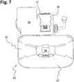
Die Kupplung kann beispielsweise ein über dem Fangmaul angeordnetes Anfahrschutzblech aufweisen und die Videokamera hinter dem Anfahrschutzblech befestigt sein. Das Anfahrschutzblech schützt vorrangig die über dem Fangmaul angebrachten Komponenten der Kupplung, insbesondere die Verschlussmechanik, gegen Beschädigungen durch eine fehlausgerichtete Zugöse. In einer Einbaulage der Videokamera hinter dem Anfahrschutzblech ist auch die Kamera während des Ankuppelns gegen mechanische Beschädigungen geschützt.The coupling can, for example, have a collision protection plate arranged above the catch and the video camera can be fastened behind the collision protection plate. The collision protection plate primarily protects the coupling components attached above the catch, especially the locking mechanism, against damage caused by a misaligned towing eye. If the video camera is installed behind the collision protection plate, the camera is also protected against mechanical damage during coupling.
Vorzugsweise ist das Anfahrschutzblech mit einem Durchbruch ausgebildet und die Videokamera fluchtend zu dem Durchbruch angeordnet. Heraus resultiert der Vorteil, dass die Kamera einerseits ein freies Sichtfeld nach hinten in Richtung des Anhängers hat und andererseits durch das Anfahrschutzblech geschützt ist. Der Durchbruch sollte derart bemessen und die Videokamera soweit zu dem Durchbruch beabstandet sein, dass der Außendurchmesser der Zugöse lediglich teilweise in den Durchbruch hineinreicht und keine Kontaktierung mit der Videokamera möglich ist.The collision protection plate is preferably designed with an opening and the video camera is arranged in alignment with the opening. This results in the advantage that the camera on the one hand has a clear field of vision to the rear in the direction of the trailer and on the other hand is protected by the collision protection plate. The opening should be dimensioned in such a way and the video camera should be spaced so far from the opening that the outer diameter of the towing eye only partially extends into the opening and no contact with the video camera is possible.
Gemäß einer weiteren, besonderen Ausführungsform kann das Fahrerassistenzsystem automatisch oder auf Fahrerfreigabe in die Motorsteuerung und/oder Getriebesteuerung und/oder Bremssteuerung und/oder Höhensteuerung der Luftfederung Einfluss nehmen. Hierbei handelt es sich um ein autark arbeitendes Assistenzsystem, welches ohne Mitwirken des Fahrers ein Annähern und Ankuppeln des Anhängers durchführt.According to a further, special embodiment, the driver assistance system can influence the engine control and / or transmission control and / or brake control and / or height control of the air suspension automatically or upon driver release. This is a self-sufficient assistance system that approaches and hitching the trailer without the driver having to do anything.
Nach dem erfindungsgemäßen Verfahren ist die Videokamera vertikal beabstandet zu der Kupplung angeordnet und die Leitmarkierung wird mittels zweier symmetrisch zur Fahrzeuglängsachse angeordneten und in rückwärtiger Richtung des Zugfahrzeugs zulaufenden Strahlenkorridoren visualisiert.According to the method according to the invention, the video camera is arranged at a vertical distance from the coupling and the guide marking is visualized by means of two radiation corridors arranged symmetrically to the longitudinal axis of the vehicle and tapering towards the rear of the towing vehicle.
In einem besonders zweckmäßigen Verfahrensschritt kann vorgesehen sein, dass die Strahlenkorridore jeweils eine Innenbegrenzungslinie sowie eine Außenbegrenzungslinie aufweisen und während einer Annäherung von Fangmaul und Zugöse korrekt angekuppelt wird, wenn ein Bezugselement der Zugöse im Videobild zwischen der Innenbegrenzungslinie und der Außenbegrenzungslinie beider Strahlenkorridore angeordnet wird.In a particularly expedient method step, it can be provided that the radiation corridors each have an inner boundary line and an outer boundary line and are correctly coupled when the catching mouth and towing eye are approaching if a reference element of the towing eye is arranged in the video image between the inner delimitation line and the outer delimitation line of both radiation corridors.
Zweckmäßigerweise wird durch eine im Videobild über beide Außenbegrenzungslinien hinausragende Zugöse visualisiert, das Zugfahrzeug mittels seiner Luftfederung anzuheben.Appropriately, a towing eye projecting beyond both outer boundary lines in the video image shows that the towing vehicle is lifted by means of its air suspension.
Dagegen kann durch eine im Videobild innerhalb beider Innenbegrenzungslinien angeordneten Zugöse visualisiert werden, das Zugfahrzeug mittels seiner Luftfederung abzusenken.On the other hand, a towing eye arranged in the video image within the two inner boundary lines can be used to visualize the lowering of the towing vehicle by means of its air suspension.
Zum besseren Verständnis wird die Erfindung nachfolgend anhand von sieben Figuren näher erläutert. Es zeigen die
1 : eine Seitenansicht auf eine Maulkupplung mit Videokamera in korrekter Ausrichtung vor einer Zugöse unmittelbar vor dem Ankuppeln;2 : ein Videobild mit Strahlenkorridoren und Zugöse entsprechend der Situation in1 ;3 : eine Seitenansicht auf eine zu niedrig ausgerichtete Maulkupplung mit Videokamera vor einer Zugöse unmittelbar vor dem Ankuppeln;4 : ein Videobild mit Strahlenkorridoren und Zugöse entsprechend der Situation in3 ;5 : eine Seitenansicht auf eine zu hoch ausgerichtete Maulkupplung mit Videokamera vor einer Zugöse unmittelbar vor dem Ankuppeln;6 : ein Videobild mit Strahlenkorridoren und Zugöse entsprechend der Situation in5 und7 : eine Vorderansicht auf eine Maulkupplung mit Anfahrschutzblech und Videokamera.
1 : a side view of a jaw coupling with video camera in the correct orientation in front of a towing eye immediately before coupling;2 : a video image with beam corridors and towing eye according to the situation in1 ;3 : a side view of a too low aligned jaw coupling with video camera in front of a towing eye immediately before coupling;4th : a video image with beam corridors and towing eye according to the situation in3 ;5 : a side view of a too high aligned jaw coupling with video camera in front of a towing eye immediately before coupling;6th : a video image with beam corridors and towing eye according to the situation in5 and7th : a front view of a jaw coupling with collision protection plate and video camera.
Die
Die Maulkupplung
In der Darstellung der
Vor dem Ankuppeln des Anhängers befindet sich der Kupplungsbolzen
Der aufgeweitete Wandabschnitt
Das in
Für eine Abschätzung der Relativlage der Zugöse
Die Ausrichtung der Strahlenkorridore
Die Strahlenkorridore
In
Die
Die Zugöse
Die
Die Zugöse
Die
In der Fahrzeuglängsachse
BezugszeichenlisteList of reference symbols
- 1010
- VideokameraVideo camera
- 1111
- AnzeigevorrichtungDisplay device
- 2020th
- VideobildVideo image
- 2121
- LeitmarkierungGuide mark
- 2222nd
- StrahlenkorridoreRadiation corridors
- 2323
- Innenbegrenzungslinie StrahlenkorridorInner boundary line of the radiation corridor
- 2424
- Außenbegrenzungslinie StrahlenkorridorExternal boundary line radiation corridor
- 3030th
- Kupplung/MaulkupplungCoupling / jaw coupling
- 3131
- FangmaulMouth
- 3232
- aufgeweiteter Wandabschnittwidened wall section
- 3333
- VerbindungsflanschConnecting flange
- 3434
- KupplungsbolzenCoupling bolt
- 3535
- AnfahrschutzblechCollision protection plate
- 3636
- Durchbruch AnfahrschutzblechBreakthrough protection plate
- 3737
- EinfahröffnungEntry opening
- 3838
- Fahrzeugrahmen ZugfahrzeugVehicle frame towing vehicle
- 3939
- BetätigungshebelOperating lever
- 4040
- ZugöseTowing eye
- 4141
- DeichselDrawbar
- aa
- Abstand Innen-/AußenbegrenzungslinieDistance inside / outside boundary line
- DzDz
- Distanz in FahrzeuglängsachseDistance in the vehicle's longitudinal axis
- RR.
- Rückwärtsfahrt ZugfahrzeugTowing vehicle backwards
- ZZ
- FahrzeuglängsachseVehicle longitudinal axis
- ∅A∅A
- Außendurchmesser ZugöseOutside diameter drawbar eye
- ∅I∅I
- Innendurchmesser ZugöseInner diameter drawbar eye
ZITATE ENTHALTEN IN DER BESCHREIBUNGQUOTES INCLUDED IN THE DESCRIPTION
Diese Liste der vom Anmelder aufgeführten Dokumente wurde automatisiert erzeugt und ist ausschließlich zur besseren Information des Lesers aufgenommen. Die Liste ist nicht Bestandteil der deutschen Patent- bzw. Gebrauchsmusteranmeldung. Das DPMA übernimmt keinerlei Haftung für etwaige Fehler oder Auslassungen.This list of the documents listed by the applicant was generated automatically and is included solely for the better information of the reader. The list is not part of the German patent or utility model application. The DPMA assumes no liability for any errors or omissions.
Zitierte PatentliteraturPatent literature cited
- DE 102014012330 A1 [0003]DE 102014012330 A1 [0003]
- EP 1377062 B1 [0004]EP 1377062 B1 [0004]
Claims (15)
Translated fromGermanPriority Applications (7)
| Application Number | Priority Date | Filing Date | Title |
|---|---|---|---|
| DE102020003141.2ADE102020003141A1 (en) | 2020-05-26 | 2020-05-26 | Driver assistance system and method for coupling a trailer to a towing vehicle |
| US17/314,444US11987181B2 (en) | 2020-05-26 | 2021-05-07 | Driver assistance system and method for coupling a trailer to a towing vehicle |
| ES21174968TES2936686T3 (en) | 2020-05-26 | 2021-05-20 | Driver assistance system and procedure for coupling a trailer to a towing vehicle |
| PL21174968.4TPL3915838T3 (en) | 2020-05-26 | 2021-05-20 | Driver assistance system and method for coupling a trailer onto a tractor |
| EP21174968.4AEP3915838B1 (en) | 2020-05-26 | 2021-05-20 | Driver assistance system and method for coupling a trailer onto a tractor |
| CN202110556910.8ACN113715565B (en) | 2020-05-26 | 2021-05-21 | Driver assistance system and method for coupling a trailer to a towing vehicle |
| JP2021086842AJP2021187431A (en) | 2020-05-26 | 2021-05-24 | Driver Assistance Systems and Methods for Coupling Trailers to Towing Vehicles |
Applications Claiming Priority (1)
| Application Number | Priority Date | Filing Date | Title |
|---|---|---|---|
| DE102020003141.2ADE102020003141A1 (en) | 2020-05-26 | 2020-05-26 | Driver assistance system and method for coupling a trailer to a towing vehicle |
Publications (1)
| Publication Number | Publication Date |
|---|---|
| DE102020003141A1true DE102020003141A1 (en) | 2021-12-02 |
Family
ID=76034517
Family Applications (1)
| Application Number | Title | Priority Date | Filing Date |
|---|---|---|---|
| DE102020003141.2AWithdrawnDE102020003141A1 (en) | 2020-05-26 | 2020-05-26 | Driver assistance system and method for coupling a trailer to a towing vehicle |
Country Status (7)
| Country | Link |
|---|---|
| US (1) | US11987181B2 (en) |
| EP (1) | EP3915838B1 (en) |
| JP (1) | JP2021187431A (en) |
| CN (1) | CN113715565B (en) |
| DE (1) | DE102020003141A1 (en) |
| ES (1) | ES2936686T3 (en) |
| PL (1) | PL3915838T3 (en) |
Cited By (2)
| Publication number | Priority date | Publication date | Assignee | Title |
|---|---|---|---|---|
| DE102022004590A1 (en)* | 2022-12-07 | 2024-06-13 | Jost-Werke Deutschland Gmbh | Camera system for accurate coupling of a trailer to a towing vehicle |
| DE102023124059A1 (en) | 2023-09-07 | 2025-03-13 | Valeo Schalter Und Sensoren Gmbh | Method for determining and displaying auxiliary information for a maneuvering maneuver of a vehicle, method for performing a maneuvering maneuver with a vehicle toward a target object, and electronic maneuvering system |
Families Citing this family (1)
| Publication number | Priority date | Publication date | Assignee | Title |
|---|---|---|---|---|
| DE102022003318A1 (en)* | 2022-09-09 | 2024-03-14 | Jost-Werke Deutschland Gmbh | ALIGNMENT SYSTEM FOR APPROACHING A VEHICLE TO A SPATIALLY DISTANCED TARGET OBJECT |
Citations (4)
| Publication number | Priority date | Publication date | Assignee | Title |
|---|---|---|---|---|
| DE102004043761A1 (en) | 2004-09-10 | 2006-03-16 | Daimlerchrysler Ag | Tow coupling monitoring method for towing vehicle, involves comparing graphic data with allowed samples and threshold values for producing assistance signals, and displaying data and signals for monitoring coupling process of coupling |
| EP1377062B1 (en) | 2001-03-29 | 2007-05-02 | Matsushita Electric Industrial Co., Ltd. | Method and device for image display on rear view camera |
| DE102014003953A1 (en) | 2014-03-20 | 2015-09-24 | Man Truck & Bus Ag | Camera-based driver assistance system of a towing vehicle, in particular of a towing vehicle of a utility vehicle combination |
| DE102014012330A1 (en) | 2014-08-20 | 2016-02-25 | Man Truck & Bus Ag | Driver assistance system for a commercial vehicle combination and method for carrying out a coupling process |
Family Cites Families (19)
| Publication number | Priority date | Publication date | Assignee | Title |
|---|---|---|---|---|
| BR9307243A (en)* | 1992-10-13 | 1999-08-24 | Presbat Products Pty Ltd | Loop movement stabilization system to inhibit undesirable lateral oscillation between a towed vehicle and a front vehicle |
| JP3483143B2 (en)* | 2001-04-09 | 2004-01-06 | 松下電器産業株式会社 | Driving support device |
| JP3945467B2 (en)* | 2003-10-02 | 2007-07-18 | 日産自動車株式会社 | Vehicle retraction support apparatus and method |
| US20050121879A1 (en)* | 2003-12-09 | 2005-06-09 | Smith Roland L. | Trailer hitch alignment system |
| US8888121B2 (en)* | 2007-01-25 | 2014-11-18 | Target Hitch Llc | Towing vehicle guidance for trailer hitch connection |
| US9516275B2 (en)* | 2011-03-02 | 2016-12-06 | Panasonic Intellectual Property Management Co., Ltd. | Driving assistance device and towing vehicle |
| GB2513392B (en)* | 2013-04-26 | 2016-06-08 | Jaguar Land Rover Ltd | System for a towing vehicle |
| GB2513393B (en)* | 2013-04-26 | 2016-02-03 | Jaguar Land Rover Ltd | Vehicle hitch assistance system |
| US9834140B2 (en)* | 2014-07-22 | 2017-12-05 | Fca Us Llc | Trailer hitch guidance method |
| JP6358123B2 (en)* | 2015-02-16 | 2018-07-18 | 株式会社デンソー | Driving assistance device |
| US20160375831A1 (en)* | 2015-06-23 | 2016-12-29 | GM Global Technology Operations LLC | Hitching assist with pan/zoom and virtual top-view |
| JP2017076833A (en)* | 2015-10-13 | 2017-04-20 | アルパイン株式会社 | Driving support device and computer program |
| US9731568B2 (en)* | 2015-12-01 | 2017-08-15 | GM Global Technology Operations LLC | Guided tow hitch control system and method |
| US10864787B2 (en)* | 2016-07-28 | 2020-12-15 | Robert Bosch Gmbh | Systems and methods for a human machine interface for a trailer hitch system |
| JP7069548B2 (en)* | 2017-03-01 | 2022-05-18 | 株式会社アイシン | Peripheral monitoring device |
| DE102017220459B4 (en)* | 2017-11-16 | 2023-10-19 | Volkswagen Aktiengesellschaft | Method and trailer coupling assistant for supporting a coupling process of a motor vehicle reversing towards a trailer, and motor vehicle |
| US10479404B2 (en)* | 2018-03-13 | 2019-11-19 | Toyota Motor Engineering & Manufacturing North America, Inc. | Backup system for a vehicle with a trailer hitch |
| US10596967B2 (en)* | 2018-03-27 | 2020-03-24 | GM Global Technology Operations LLC | Towing arrangement with integrated imaging connection device |
| CN209209057U (en)* | 2018-10-29 | 2019-08-06 | 陕西汽车集团有限责任公司 | A kind of traction alignment device |
- 2020
- 2020-05-26DEDE102020003141.2Apatent/DE102020003141A1/ennot_activeWithdrawn
- 2021
- 2021-05-07USUS17/314,444patent/US11987181B2/enactiveActive
- 2021-05-20ESES21174968Tpatent/ES2936686T3/enactiveActive
- 2021-05-20EPEP21174968.4Apatent/EP3915838B1/enactiveActive
- 2021-05-20PLPL21174968.4Tpatent/PL3915838T3/enunknown
- 2021-05-21CNCN202110556910.8Apatent/CN113715565B/enactiveActive
- 2021-05-24JPJP2021086842Apatent/JP2021187431A/enactivePending
Patent Citations (4)
| Publication number | Priority date | Publication date | Assignee | Title |
|---|---|---|---|---|
| EP1377062B1 (en) | 2001-03-29 | 2007-05-02 | Matsushita Electric Industrial Co., Ltd. | Method and device for image display on rear view camera |
| DE102004043761A1 (en) | 2004-09-10 | 2006-03-16 | Daimlerchrysler Ag | Tow coupling monitoring method for towing vehicle, involves comparing graphic data with allowed samples and threshold values for producing assistance signals, and displaying data and signals for monitoring coupling process of coupling |
| DE102014003953A1 (en) | 2014-03-20 | 2015-09-24 | Man Truck & Bus Ag | Camera-based driver assistance system of a towing vehicle, in particular of a towing vehicle of a utility vehicle combination |
| DE102014012330A1 (en) | 2014-08-20 | 2016-02-25 | Man Truck & Bus Ag | Driver assistance system for a commercial vehicle combination and method for carrying out a coupling process |
Cited By (2)
| Publication number | Priority date | Publication date | Assignee | Title |
|---|---|---|---|---|
| DE102022004590A1 (en)* | 2022-12-07 | 2024-06-13 | Jost-Werke Deutschland Gmbh | Camera system for accurate coupling of a trailer to a towing vehicle |
| DE102023124059A1 (en) | 2023-09-07 | 2025-03-13 | Valeo Schalter Und Sensoren Gmbh | Method for determining and displaying auxiliary information for a maneuvering maneuver of a vehicle, method for performing a maneuvering maneuver with a vehicle toward a target object, and electronic maneuvering system |
Also Published As
| Publication number | Publication date |
|---|---|
| JP2021187431A (en) | 2021-12-13 |
| US20210370830A1 (en) | 2021-12-02 |
| US11987181B2 (en) | 2024-05-21 |
| ES2936686T3 (en) | 2023-03-21 |
| EP3915838A1 (en) | 2021-12-01 |
| CN113715565B (en) | 2024-07-05 |
| CN113715565A (en) | 2021-11-30 |
| EP3915838B1 (en) | 2022-11-30 |
| PL3915838T3 (en) | 2023-04-03 |
Similar Documents
| Publication | Publication Date | Title |
|---|---|---|
| EP3915838B1 (en) | Driver assistance system and method for coupling a trailer onto a tractor | |
| EP2987663B1 (en) | Driver assistance system for a commercial vehicle trailer assembly and method for performing a coupling procedure | |
| DE102019008316A1 (en) | Method for object recognition and distance determination | |
| EP3047986A1 (en) | Coupling sensor | |
| DE102008023504A1 (en) | Track monitoring system for a vehicle and method for its operation | |
| EP3710288B1 (en) | Method and trailer-coupling assistance for assisting in the coupling process of a motor vehicle reversing towards a trailer | |
| DE102016109954A1 (en) | A method for assisting a driver of a team when maneuvering the team, driver assistance system and motor vehicle | |
| DE102018102244B4 (en) | Rear of vehicle | |
| DE102014015753A1 (en) | Method and device for assisting a driver of a vehicle combination, in particular a utility vehicle combination | |
| EP3464019B1 (en) | Verification of the integrity of a train of vehicles | |
| EP4331872A1 (en) | Coupling device for a towing vehicle, comprising object detection means attached thereto | |
| DE19816822A1 (en) | Trailer monitoring system | |
| EP3143861A1 (en) | Agricultural mower and trailer and method for operating the mower | |
| DE102011108322B4 (en) | Connection of an add-on element to a commercial vehicle frame | |
| DE102006006395B4 (en) | Cover for towing hitches of motor vehicles | |
| DE102019204418B3 (en) | Camera arm device for a mirror replacement system for a motor vehicle and motor vehicle | |
| DE102016112532A1 (en) | Agricultural trailer device and train combination with such a trailer device | |
| EP3809322A1 (en) | Device for preventing the collision of a vehicle door of a motor vehicle with a vehicle wheel | |
| DE102006037220B4 (en) | Fang with mechanical stop | |
| DE102018010096A1 (en) | Method of visualizing a trailer hitch and trailer hitch | |
| DE102019113503A1 (en) | Coupling system for a mobile working machine and retrofitting system for a trailer coupling of a mobile working machine and mobile working machine with the coupling system | |
| DE102019213525B3 (en) | Avoidance system for a camera arm for observing traffic behind a vehicle | |
| DE102022004590A1 (en) | Camera system for accurate coupling of a trailer to a towing vehicle | |
| WO2019011380A1 (en) | METHOD FOR AVOIDING THE CRITICAL SITUATIONS OF A COUPLING, IN WHICH A DISTANCE BETWEEN POINTS OF THE HITCH IS DETERMINED, DRIVING ASSISTANCE SYSTEM AND VEHICLE | |
| DE676578C (en) | Universal joint trailer coupling for off-road vehicles |
Legal Events
| Date | Code | Title | Description |
|---|---|---|---|
| R012 | Request for examination validly filed | ||
| R016 | Response to examination communication | ||
| R120 | Application withdrawn or ip right abandoned |