DE102019205298A1 - tires - Google Patents
tiresDownload PDFInfo
- Publication number
- DE102019205298A1 DE102019205298A1DE102019205298.3ADE102019205298ADE102019205298A1DE 102019205298 A1DE102019205298 A1DE 102019205298A1DE 102019205298 ADE102019205298 ADE 102019205298ADE 102019205298 A1DE102019205298 A1DE 102019205298A1
- Authority
- DE
- Germany
- Prior art keywords
- receiving device
- electromagnetic transmitting
- tire
- rubber material
- homogeneous rubber
- Prior art date
- Legal status (The legal status is an assumption and is not a legal conclusion. Google has not performed a legal analysis and makes no representation as to the accuracy of the status listed.)
- Pending
Links
- 239000000463materialSubstances0.000claimsabstractdescription62
- 239000011324beadSubstances0.000claimsabstractdescription26
- 239000002318adhesion promoterSubstances0.000claimsdescription5
- 239000011248coating agentSubstances0.000claimsdescription5
- 238000000576coating methodMethods0.000claimsdescription5
- 230000002787reinforcementEffects0.000description3
- BUHVIAUBTBOHAG-FOYDDCNASA-N(2r,3r,4s,5r)-2-[6-[[2-(3,5-dimethoxyphenyl)-2-(2-methylphenyl)ethyl]amino]purin-9-yl]-5-(hydroxymethyl)oxolane-3,4-diolChemical compoundCOC1=CC(OC)=CC(C(CNC=2C=3N=CN(C=3N=CN=2)[C@H]2[C@@H]([C@H](O)[C@@H](CO)O2)O)C=2C(=CC=CC=2)C)=C1BUHVIAUBTBOHAG-FOYDDCNASA-N0.000description1
- 229920000106Liquid crystal polymerPolymers0.000description1
- 239000004977Liquid-crystal polymers (LCPs)Substances0.000description1
- 230000005540biological transmissionEffects0.000description1
- 238000010276constructionMethods0.000description1
- 230000003993interactionEffects0.000description1
- 239000004033plasticSubstances0.000description1
- 238000009987spinningMethods0.000description1
- 238000009941weavingMethods0.000description1
Images

Classifications
- B—PERFORMING OPERATIONS; TRANSPORTING
- B29—WORKING OF PLASTICS; WORKING OF SUBSTANCES IN A PLASTIC STATE IN GENERAL
- B29D—PRODUCING PARTICULAR ARTICLES FROM PLASTICS OR FROM SUBSTANCES IN A PLASTIC STATE
- B29D30/00—Producing pneumatic or solid tyres or parts thereof
- B29D30/0061—Accessories, details or auxiliary operations not otherwise provided for
- B—PERFORMING OPERATIONS; TRANSPORTING
- B29—WORKING OF PLASTICS; WORKING OF SUBSTANCES IN A PLASTIC STATE IN GENERAL
- B29D—PRODUCING PARTICULAR ARTICLES FROM PLASTICS OR FROM SUBSTANCES IN A PLASTIC STATE
- B29D30/00—Producing pneumatic or solid tyres or parts thereof
- B29D30/06—Pneumatic tyres or parts thereof (e.g. produced by casting, moulding, compression moulding, injection moulding, centrifugal casting)
- B29D30/48—Bead-rings or bead-cores; Treatment thereof prior to building the tyre
- B—PERFORMING OPERATIONS; TRANSPORTING
- B60—VEHICLES IN GENERAL
- B60C—VEHICLE TYRES; TYRE INFLATION; TYRE CHANGING; CONNECTING VALVES TO INFLATABLE ELASTIC BODIES IN GENERAL; DEVICES OR ARRANGEMENTS RELATED TO TYRES
- B60C15/00—Tyre beads, e.g. ply turn-up or overlap
- B60C15/06—Flipper strips, fillers, or chafing strips and reinforcing layers for the construction of the bead
- B60C15/0603—Flipper strips, fillers, or chafing strips and reinforcing layers for the construction of the bead characterised by features of the bead filler or apex
- B60C15/0607—Flipper strips, fillers, or chafing strips and reinforcing layers for the construction of the bead characterised by features of the bead filler or apex comprising several parts, e.g. made of different rubbers
- B—PERFORMING OPERATIONS; TRANSPORTING
- B60—VEHICLES IN GENERAL
- B60C—VEHICLE TYRES; TYRE INFLATION; TYRE CHANGING; CONNECTING VALVES TO INFLATABLE ELASTIC BODIES IN GENERAL; DEVICES OR ARRANGEMENTS RELATED TO TYRES
- B60C19/00—Tyre parts or constructions not otherwise provided for
- B—PERFORMING OPERATIONS; TRANSPORTING
- B29—WORKING OF PLASTICS; WORKING OF SUBSTANCES IN A PLASTIC STATE IN GENERAL
- B29D—PRODUCING PARTICULAR ARTICLES FROM PLASTICS OR FROM SUBSTANCES IN A PLASTIC STATE
- B29D30/00—Producing pneumatic or solid tyres or parts thereof
- B29D30/0061—Accessories, details or auxiliary operations not otherwise provided for
- B29D2030/0083—Attaching monitoring devices to tyres before or after vulcanization by inserting them inside tyre cavities
- B—PERFORMING OPERATIONS; TRANSPORTING
- B29—WORKING OF PLASTICS; WORKING OF SUBSTANCES IN A PLASTIC STATE IN GENERAL
- B29D—PRODUCING PARTICULAR ARTICLES FROM PLASTICS OR FROM SUBSTANCES IN A PLASTIC STATE
- B29D30/00—Producing pneumatic or solid tyres or parts thereof
- B29D30/06—Pneumatic tyres or parts thereof (e.g. produced by casting, moulding, compression moulding, injection moulding, centrifugal casting)
- B29D30/48—Bead-rings or bead-cores; Treatment thereof prior to building the tyre
- B29D2030/481—Fillers or apexes
- B—PERFORMING OPERATIONS; TRANSPORTING
- B29—WORKING OF PLASTICS; WORKING OF SUBSTANCES IN A PLASTIC STATE IN GENERAL
- B29D—PRODUCING PARTICULAR ARTICLES FROM PLASTICS OR FROM SUBSTANCES IN A PLASTIC STATE
- B29D30/00—Producing pneumatic or solid tyres or parts thereof
- B29D30/06—Pneumatic tyres or parts thereof (e.g. produced by casting, moulding, compression moulding, injection moulding, centrifugal casting)
- B29D30/48—Bead-rings or bead-cores; Treatment thereof prior to building the tyre
- B29D2030/486—Additional components for the tyre bead areas, e.g. cushioning elements, chafers, flippers
Landscapes
- Engineering & Computer Science (AREA)
- Mechanical Engineering (AREA)
- Tires In General (AREA)
- Tyre Moulding (AREA)
Abstract
Translated fromGermanDescription
Translated fromGermanDie Erfindung bezieht sich auf einen Reifen.
Die Erfindung geht aus von einem Reifen, wobei der Reifen um eine Rotationsachse in eine Umlaufrichtung rotierbar ist. Der Reifen weist mindestens eine elektromagnetische Sende-und Empfangsvorrichtung, mindestens einen Wulstkern und mindestens einen Apex auf. Der mindestens eine Apex ist aus einem ersten homogenen Kautschukmaterial und aus einem zweiten homogenen Kautschukmaterial ausgebildet. Das erste homogene Kautschukmaterial ist an dem mindestens einen Wulstkern angeordnet und das erste homogene Kautschukmaterial ist räumlich zwischen dem mindestens einen Wulstkern und dem einen zweiten homogenen Kautschukmaterial angeordnet.
Der Reifen weist insbesondere mindestens eine Karkasslage auf.The invention relates to a tire.
The invention is based on a tire, the tire being rotatable about an axis of rotation in a direction of rotation. The tire has at least one electromagnetic transmitting and receiving device, at least one bead core and at least one apex. The at least one apex is formed from a first homogeneous rubber material and from a second homogeneous rubber material. The first homogeneous rubber material is arranged on the at least one bead core and the first homogeneous rubber material is spatially arranged between the at least one bead core and the one second homogeneous rubber material.
In particular, the tire has at least one carcass ply.
Bei der elektromagnetischen Sende- und Empfangsvorrichtung handelt es sich insbesondere um eine RFID-Vorrichtung. RFID steht für Radio Frequency Identification und bedeutet Identifizierung mit Hilfe elektromagnetischer Wellen.The electromagnetic transmitting and receiving device is in particular an RFID device. RFID stands for Radio Frequency Identification and means identification using electromagnetic waves.
Aus dem Stand der Technik sind elektromagnetische Sende- und Empfangsvorrichtungen für Reifen bekannt. Beispielsweise wird in der
Bei den aus dem Stand der Technik bekannten Reifen mit elektromagnetischen Sende- und Empfangsvorrichtungen könnte die Anordnung der elektromagnetischen Sende- und Empfangsvorrichtung mit nicht optimalen Bedingungen für den Betrieb der elektromagnetischen Sende- und Empfangsvorrichtung verbunden sein.In the tires known from the prior art with electromagnetic transmitting and receiving devices, the arrangement of the electromagnetic transmitting and receiving device could be associated with non-optimal conditions for the operation of the electromagnetic transmitting and receiving device.
Der Erfindung liegt daher die Aufgabe zugrunde, einen Reifen mit einer elektromagnetischen Sende- und Empfangsvorrichtung bereitzustellen, bei dem ein Betrieb der elektromagnetischen Sende- und Empfangsvorrichtung innerhalb des Reifens verbessert wird.The invention is therefore based on the object of providing a tire with an electromagnetic transmitting and receiving device in which an operation of the electromagnetic transmitting and receiving device within the tire is improved.
Gelöst wird die erfindungsgemäße Aufgabe dadurch, dass die mindestens eine elektromagnetische Sende- und Empfangsvorrichtung innerhalb des mindestens einen Apex angeordnet ist.
Durch den erfindungsgemäßen Umstand, wonach die mindestens eine elektromagnetische Sende- und Empfangsvorrichtung innerhalb des mindestens einen Apex angeordnet ist, wird die elektromagnetische Sende- und Empfangsvorrichtung innerhalb eines Bereichs des Reifens angeordnet, der eine Materialhomogenität aufweist. Diese Materialhomogenität stellt einen gegenüber den aus dem Stand der Technik bekannten Lösungen verbesserten Betrieb der elektromagnetischen Sende- und Empfangsvorrichtung sicher. Darüber hinaus ist eine weitere Verwendung von Fremdmaterial nicht erforderlich.
Das Material des Apex weist solche dielektrischen Eigenschaften auf, dass eine optimale Einstellung der elektromagnetischen Sendefähigkeit der elektromagnetischen Sende- und Empfangsvorrichtung ermöglicht werden kann.
Somit wird ein verbesserter Reifen bereitgestellt.The object according to the invention is achieved in that the at least one electromagnetic transmitting and receiving device is arranged within the at least one apex.
Due to the fact according to the invention, according to which the at least one electromagnetic transmitting and receiving device is arranged within the at least one apex, the electromagnetic transmitting and receiving device is arranged within a region of the tire which has a material homogeneity. This homogeneity of material ensures an improved operation of the electromagnetic transmitting and receiving device compared to the solutions known from the prior art. In addition, no further use of foreign material is required.
The material of the apex has such dielectric properties that an optimal setting of the electromagnetic transmission capability of the electromagnetic transmitting and receiving device can be made possible.
Thus, an improved tire is provided.
Bei dem Reifen handelt es sich insbesondere um einen Lkw-Reifen, um einen Pkw-Reifen oder um einen Fahrrad-Reifen oder um einen Motorrad-Reifen.The tire is in particular a truck tire, a car tire or a bicycle tire or a motorcycle tire.
Weitere vorteilhafte Ausgestaltungsformen der vorliegenden Erfindung sind Gegenstand der Unteransprüche.Further advantageous embodiments of the present invention are the subject of the subclaims.
Gemäß einer vorzugsweisen Ausgestaltungsform der vorliegenden Erfindung ist die mindestens eine elektromagnetische Sende- und Empfangsvorrichtung vollständig innerhalb des mindestens einen Apex angeordnet.According to a preferred embodiment of the present invention, the at least one electromagnetic transmitting and receiving device is arranged completely within the at least one apex.
Gemäß einer vorzugsweisen Ausgestaltungsform der vorliegenden Erfindung weist die mindestens eine elektromagnetische Sende- und Empfangsvorrichtung eine Haftvermittlerbeschichtung auf.According to a preferred embodiment of the present invention, the at least one electromagnetic transmitting and receiving device has an adhesion promoter coating.
Durch den erfindungsgemäßen Umstand, wonach die mindestens eine elektromagnetische Sende- und Empfangsvorrichtung eine Haftvermittlerbeschichtung aufweist, kann eine verbesserte Anbindung der mindestens einen elektromagnetischen Sende- und Empfangsvorrichtung innerhalb des Apex sichergestellt werden.Due to the fact according to the invention, according to which the at least one electromagnetic transmitting and receiving device has an adhesion promoter coating, an improved connection of the at least one electromagnetic transmitting and receiving device within the apex can be ensured.
Gemäß einer nächsten vorzugsweisen Ausgestaltungsform der vorliegenden Erfindung weist die mindestens eine elektromagnetische Sende- und Empfangsvorrichtung eine Informationsspeicherkomponente und mindestens eine Antenne auf, wobei die mindestens eine Antenne in ein Garn eingebracht ist oder die mindestens eine Antenne und die Informationsspeicherkomponente in ein Garn eingebracht sind. Insbesondere ist die mindestens eine Antenne in das Garn eingewoben oder eingesponnen. Einspinnen oder Einweben sind besondere Ausführungsformen des Einbringens. Das Garn ist insbesondere aus einem Kunststoff oder aus einem Flüssigkristallpolymer ausgebildet.According to a next preferred embodiment of the present invention, the at least one electromagnetic transmitting and receiving device has an information storage component and at least one antenna, the at least one antenna being incorporated into a yarn or the at least one antenna and the information storage component being incorporated into a yarn. In particular, the at least one antenna is woven or spun into the yarn. Spinning or weaving are special embodiments of the introduction. The yarn is formed in particular from a plastic or from a liquid crystal polymer.
Durch den erfindungsgemäßen Umstand, wonach die mindestens eine elektromagnetische Sende-und-Empfangsvorrichtung eine Informationsspeicherkomponente und mindestens eine Antenne aufweist, wobei die mindestens eine Antenne in ein Garn eingebracht ist, wird eine derartige Konstruktion bereitgestellt, die weniger Raum innerhalb eines Reifens einnimmt, als es bei aus dem Stand der Technik bekannten elektromagnetischen Sende- und Empfangsvorrichtungen der Fall ist. Dadurch, dass die elektromagnetische Sende- und Empfangsvorrichtung weniger Raum innerhalb des Reifens beansprucht, wird die Wahrscheinlichkeit einer unerwünschten Wechselwirkung mit dem Reifen vermindert.Due to the fact according to the invention, according to which the at least one electromagnetic transmitting and receiving device has an information storage component and at least one antenna, the at least one antenna being incorporated into a yarn, such a device becomes Provided construction that takes up less space within a tire than is the case with known from the prior art electromagnetic transmitting and receiving devices. Since the electromagnetic transmitting and receiving device takes up less space inside the tire, the probability of an undesired interaction with the tire is reduced.
Gemäß einer nächsten vorzugsweisen Ausgestaltungsform der vorliegenden Erfindung ist die mindestens eine elektromagnetische Sende- und Empfangsvorrichtung vollständig innerhalb des zweiten homogenen Kautschukmaterials angeordnet.According to a next preferred embodiment of the present invention, the at least one electromagnetic transmitting and receiving device is arranged completely within the second homogeneous rubber material.
Die mindestens eine elektromagnetische Sende- und Empfangsvorrichtung ist insbesondere vollständig von dem zweiten homogenen Kautschukmaterial umgeben.The at least one electromagnetic transmitting and receiving device is in particular completely surrounded by the second homogeneous rubber material.
Gemäß einer nächsten vorzugsweisen Ausgestaltungsform der vorliegenden Erfindung beträgt ein erster räumlicher Abstand zwischen einem ersten Oberflächenpunkt der mindestens einen elektromagnetischen Sende- und Empfangsvorrichtung zu einem ersten Oberflächenpunkt des ersten homogenen Kautschukmaterials mindestens 5 mm. Dabei handelt es sich bei dem ersten Oberflächenpunkt der mindestens einen elektromagnetischen Sende- und Empfangsvorrichtung und bei dem ersten Oberflächenpunkt des ersten homogenen Kautschukmaterials um die räumlich einander nächstgelegenen Oberflächenpunkte der mindestens einen elektromagnetischen Sende- und Empfangsvorrichtung und des ersten homogenen Kautschukmaterials.According to a next preferred embodiment of the present invention, a first spatial distance between a first surface point of the at least one electromagnetic transmitting and receiving device and a first surface point of the first homogeneous rubber material is at least 5 mm. The first surface point of the at least one electromagnetic transmitting and receiving device and the first surface point of the first homogeneous rubber material are the spatially closest surface points of the at least one electromagnetic transmitting and receiving device and the first homogeneous rubber material.
Durch den erfindungsgemäßen Umstand, wonach ein erster räumlicher Abstand zwischen einem ersten Oberflächenpunkt der mindestens einen elektromagnetischen Sende- und Empfangsvorrichtung zu einem ersten Oberflächenpunkt des ersten homogenen Kautschukmaterials mindestens 5 mm beträgt, wobei es sich bei dem ersten Oberflächenpunkt der mindestens einen elektromagnetischen Sende- und Empfangsvorrichtung und bei dem ersten Oberflächenpunkt des ersten homogenen Kautschukmaterials um die räumlich einander nächstgelegenen Oberflächenpunkte der mindestens einen elektromagnetischen Sende- und Empfangsvorrichtung und des ersten homogenen Kautschukmaterials handelt, wird ein mechanischer Schutz der mindestens einen elektromagnetischen Sende- und Empfangsvorrichtung sichergestellt und es wird sichergestellt, dass die mindestens eine elektromagnetische Sende- und Empfangsvorrichtung innerhalb einer homogegen Kautschukumgebung angeordnet ist.Due to the fact according to the invention, according to which a first spatial distance between a first surface point of the at least one electromagnetic transmitting and receiving device and a first surface point of the first homogeneous rubber material is at least 5 mm, the first surface point of the at least one electromagnetic transmitting and receiving device and when the first surface point of the first homogeneous rubber material is the spatially closest surface points of the at least one electromagnetic transmitting and receiving device and the first homogeneous rubber material, mechanical protection of the at least one electromagnetic transmitting and receiving device is ensured and it is ensured that the at least one electromagnetic transmitting and receiving device is arranged within a homogeneous rubber environment.
Gemäß einer nächsten vorzugsweisen Ausgestaltungsform der vorliegenden Erfindung ist die mindestens eine elektromagnetische Sende- und Empfangsvorrichtung vollständig innerhalb des ersten homogenen Kautschukmaterials angeordnet.
Die mindestens eine elektromagnetische Sende- und Empfangsvorrichtung ist insbesondere vollständig von dem ersten homogenen Kautschukmaterial umgeben.According to a next preferred embodiment of the present invention, the at least one electromagnetic transmitting and receiving device is arranged completely within the first homogeneous rubber material.
The at least one electromagnetic transmitting and receiving device is in particular completely surrounded by the first homogeneous rubber material.
Gemäß einer nächsten vorzugsweisen Ausgestaltungsform der vorliegenden Erfindung beträgt ein zweiter räumlicher Abstand zwischen einem zweiten Oberflächenpunkt der mindestens einen elektromagnetischen Sende- und Empfangsvorrichtung zu einem ersten Oberflächenpunkt des zweiten homogenen Kautschukmaterials mindestens 5 mm. Dabei handelt es sich bei dem zweiten Oberflächenpunkt der mindestens einen elektromagnetischen Sende- und Empfangsvorrichtung und bei dem ersten Oberflächenpunkt des zweiten homogenen Kautschukmaterials um die räumlich einander nächstgelegenen Oberflächenpunkte der mindestens einen elektromagnetischen Sende- und Empfangsvorrichtung und des zweiten homogenen Kautschukmaterials.According to a next preferred embodiment of the present invention, a second spatial distance between a second surface point of the at least one electromagnetic transmitting and receiving device and a first surface point of the second homogeneous rubber material is at least 5 mm. The second surface point of the at least one electromagnetic transmitting and receiving device and the first surface point of the second homogeneous rubber material are the spatially closest surface points of the at least one electromagnetic transmitting and receiving device and the second homogeneous rubber material.
Durch den erfindungsgemäßen Umstand, wonach ein zweiter räumlicher Abstand zwischen einem zweiten Oberflächenpunkt der mindestens einen elektromagnetischen Sende- und Empfangsvorrichtung zu einem ersten Oberflächenpunkt des zweiten homogenen Kautschukmaterials mindestens 5 mm beträgt, wobei es sich bei dem zweiten Oberflächenpunkt der mindestens einen elektromagnetischen Sende- und Empfangsvorrichtung und bei dem ersten Oberflächenpunkt des zweiten homogenen Kautschukmaterials um die räumlich einander nächstgelegenen Oberflächenpunkte der mindestens einen elektromagnetischen Sende- und Empfangsvorrichtung und des zweiten homogenen Kautschukmaterials handelt, wird ein mechanischer Schutz der mindestens einen elektromagnetischen Sende- und Empfangsvorrichtung sichergestellt und es wird sichergestellt, dass die mindestens eine elektromagnetische Sende- und Empfangsvorrichtung innerhalb einer homogegen Kautschukumgebung angeordnet ist.Due to the fact according to the invention that a second spatial distance between a second surface point of the at least one electromagnetic transmitting and receiving device and a first surface point of the second homogeneous rubber material is at least 5 mm, the second surface point of the at least one electromagnetic transmitting and receiving device being at least 5 mm and when the first surface point of the second homogeneous rubber material is the spatially closest surface points of the at least one electromagnetic transmitting and receiving device and the second homogeneous rubber material, mechanical protection of the at least one electromagnetic transmitting and receiving device is ensured and it is ensured that the at least one electromagnetic transmitting and receiving device is arranged within a homogeneous rubber environment.
Gemäß einer nächsten vorzugsweisen Ausgestaltungsform der vorliegenden Erfindung beträgt ein dritter räumlicher Abstand zwischen einem dritten Oberflächenpunkt der mindestens einen elektromagnetischen Sende- und Empfangsvorrichtung zu einem Endpunkt einer Karkasslage des Reifens mindestens 10 mm. Bei dem dritten Oberflächenpunkt der mindestens einen elektromagnetischen Sende- und Empfangsvorrichtung und bei dem Endpunkt der Karkasslage des Reifens handelt es sich um die räumlich einander nächstgelegenen Oberflächenpunkte der mindestens einen elektromagnetischen Sende- und Empfangsvorrichtung und der Karkasslage des Reifens handelt.According to a next preferred embodiment of the present invention, a third spatial distance between a third surface point of the at least one electromagnetic transmitting and receiving device and an end point of a carcass ply of the tire is at least 10 mm. The third surface point of the at least one electromagnetic transmitting and receiving device and the end point of the carcass ply of the tire are the spatially closest surface points of the at least one electromagnetic transmitting and receiving device and the carcass ply of the tire.
Somit wird insbesondere ein minimaler räumlicher Abstand zwischen der mindestens einen elektromagnetischen Sende- und Empfangsvorrichtung zu der Karkasslage eingehalten. Dies führt dazu, dass die mindestens eine elektromagnetische Sende- und Empfangsvorrichtung kaum elektromagnetisch abgeschirmt wird. Bei der Karkasslage handelt es sich um die dem Apex räumlich nächstgelegene Karkasslage.Thus, in particular, a minimum spatial distance between the at least one electromagnetic transmitting and receiving device and the carcass ply is maintained. This means that the at least one electromagnetic transmitting and receiving device is hardly electromagnetically shielded. The carcass ply is the carcass ply that is spatially closest to the apex.
Gemäß einer nächsten vorzugsweisen Ausgestaltungsform der vorliegenden Erfindung beträgt ein dritter räumlicher Abstand mit einer positiven Komponente in radialer Richtung zwischen einem dritten Oberflächenpunkt der mindestens einen elektromagnetischen Sende-und Empfangsvorrichtung zu einem Endpunkt einer Karkasslage des Reifens mindestens 10 mm. Somit liegt die elektromagnetische Sende- und Empfangsvorrichtung ausgehend von der Rotationsachse in radialer Richtung weiter von der Rotationsachse entfernt als der Endpunkt der Karkasslage. Dadurch wird eine elektromagnetische Abschirmung der elektromagnetischen Sende- und Empfangsvorrichtung durch die Karkasslage weitestgehend vermieden.According to a next preferred embodiment of the present invention, a third spatial distance with a positive component in the radial direction between a third surface point of the at least one electromagnetic transmitting and receiving device and an end point of a carcass ply of the tire is at least 10 mm. Thus, starting from the axis of rotation, the electromagnetic transmitting and receiving device lies further away from the axis of rotation in the radial direction than the end point of the carcass ply. As a result, electromagnetic shielding of the electromagnetic transmitting and receiving device by the carcass ply is largely avoided.
Positive Komponente bedeutet, dass die Richtung von der Rotationsachse weg weist.Positive component means that the direction points away from the axis of rotation.
Die radiale Richtung weist rechtwinklig von der Rotationsachse weg.The radial direction points away from the axis of rotation at right angles.
Gemäß einer nächsten vorzugsweisen Ausgestaltungsform der vorliegenden Erfindung beträgt ein vierter räumlicher Abstand zwischen einem vierten Oberflächenpunkt der mindestens einen elektromagnetischen Sende- und Empfangsvorrichtung zu einem Endpunkt eines Wulstverstärkers des Reifens mindestens 10 mm. Bei dem vierten Oberflächenpunkt der mindestens einen elektromagnetischen Sende- und Empfangsvorrichtung und bei dem Endpunkt des Wulstverstärkers des Reifens handelt es sich um die räumlich einander nächstgelegenen Oberflächenpunkte der mindestens einen elektromagnetischen Sende- und Empfangsvorrichtung und des Wulstverstärkers des Reifens.
Somit wird insbesondere ein minimaler räumlicher Abstand zwischen der mindestens einen elektromagnetischen Sende- und Empfangsvorrichtung zu dem Wulstverstärker eingehalten. Dies führt dazu, dass die mindestens eine elektromagnetische Sende- und Empfangsvorrichtung kaum elektromagnetisch abgeschirmt wird. Bei dem Wulstverstärker handelt es sich um den dem Apex räumlich nächstgelegenen Wulstverstärker.According to a next preferred embodiment of the present invention, a fourth spatial distance between a fourth surface point of the at least one electromagnetic transmitting and receiving device and an end point of a chipper of the tire is at least 10 mm. The fourth surface point of the at least one electromagnetic transmitting and receiving device and the end point of the chipper of the tire are the spatially closest surface points of the at least one electromagnetic transmitting and receiving device and of the chipper of the tire.
In particular, a minimal spatial distance between the at least one electromagnetic transmitting and receiving device and the bead reinforcement is thus maintained. This means that the at least one electromagnetic transmitting and receiving device is hardly electromagnetically shielded. The chipper is the chipper that is spatially closest to the apex.
Gemäß einer nächsten vorzugsweisen Ausgestaltungsform der vorliegenden Erfindung beträgt ein vierter räumlicher Abstand mit einer positiven Komponente in radialer Richtung zwischen einem vierten Oberflächenpunkt der mindestens einen elektromagnetischen Sende- und Empfangsvorrichtung zu einem Endpunkt eines Wulstverstärkers des Reifens mindestens 10 mm.According to a next preferred embodiment of the present invention, a fourth spatial distance with a positive component in the radial direction between a fourth surface point of the at least one electromagnetic transmitting and receiving device and an end point of a bead reinforcement of the tire is at least 10 mm.
Somit liegt die elektromagnetische Sende- und Empfangsvorrichtung ausgehend von der Rotationsachse in radialer Richtung weiter von der Rotationsachse entfernt als der Endpunkt des Wulstverstärkers. Dadurch wird eine elektromagnetische Abschirmung der elektromagnetischen Sende- und Empfangsvorrichtung durch den Wulstverstärker weitestgehend vermieden.Thus, starting from the axis of rotation, the electromagnetic transmitting and receiving device lies further away from the axis of rotation in the radial direction than the end point of the chipper. As a result, electromagnetic shielding of the electromagnetic transmitting and receiving device by the bead reinforcement is largely avoided.
Positive Komponente bedeutet, dass die Richtung von der Rotationsachse weg weist.Positive component means that the direction points away from the axis of rotation.
Die radiale Richtung weist rechtwinklig von der Rotationsachse weg.The radial direction points away from the axis of rotation at right angles.
Weitere Merkmale, Vorteile und Einzelheiten, auf die die Erfindung in ihrem Umfang aber nicht beschränkt ist, werden nun anhand der Zeichnungen näher beschrieben.Further features, advantages and details, to which the scope of the invention is not limited, will now be described in more detail with reference to the drawings.
Es zeigt:
1 : Eine schematische Darstellung eines erfindungsgemäßen Reifens in Radial schnittansicht;2 : Eine schematische Darstellung einer erfindungsgemäßen elektromagnetischen Sende-und Empfangsvorrichtung zur Anordnung in einem erfindungsgemäßen Reifen;3 : Eine schematische Darstellung eines Wulstbereichs eines erfindungsgemäßen Reifens;4 : Eine schematische Darstellung eines Wulstbereichs eines erfindungsgemäßen Reifens gemäß einer Ausführungsform;5 : Eine schematische Darstellung eines Wulstbereichs eines erfindungsgemäßen Reifens gemäß einer weiteren Ausführungsform;6 : Eine schematische Darstellung eines Wulstbereichs eines erfindungsgemäßen Reifens gemäß einer weiteren Ausführungsform.
1 : A schematic representation of a tire according to the invention in a radial sectional view;2 : A schematic representation of an electromagnetic transmitting and receiving device according to the invention for arrangement in a tire according to the invention;3 : A schematic representation of a bead area of a tire according to the invention;4th : A schematic representation of a bead area of a tire according to the invention according to an embodiment;5 : A schematic representation of a bead area of a tire according to the invention according to a further embodiment;6th : A schematic representation of a bead area of a tire according to the invention according to a further embodiment.
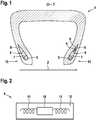
In der
Der mindestens eine Wulstkern
Der mindestens eine Apex
Die mindestens eine elektromagnetische Sende- und Empfangsvorrichtung
Gemäß der in der
The at least one
The at least one apex
The at least one electromagnetic transmitting and receiving device
According to the
In der
Die zwei Antennen
The two
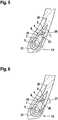
In der
Gemäß der in der
Bei dem ersten Oberflächenpunkt
At the first surface point
In der
Gemäß der in der
Bei dem zweiten Oberflächenpunkt
According to the
At the second surface point
In der
Gemäß der in der
Gemäß der Darstellung in der
According to the
As shown in the
In der
Gemäß der in der
Gemäß der Darstellung in der
According to the
As shown in the
BezugszeichenlisteList of reference symbols
(ist Teil der Beschreibung)
- 1
- Elektromagnetische Sende- und Empfangsvorrichtung
- 2
- Rotationsachse
- 3
- Umlaufrichtung
- 4
- Elektromagnetische Sende- und Empfangsvorrichtung
- 5
- Wulstkern
- 6
- Apex
- 7
- Erstes homogenes Kautschukmaterial
- 8
- Zweites homogenes kautschukmaterial
- 9
- Haftvermittlerbeschichtung
- 10
- Informationsspeicherkomponente
- 11
- Antenne
- 12
- Garn
- 13
- Wulstbereich
- 14
- Erster räumlicher Abstand
- 15
- Erster Oberflächenpunkt der mindestens einen elektromagnetischen Sende- und Empfangsvorrichtung
- 16
- Erster Oberflächenpunkt des ersten homogenen Kautschukmaterials
- 17
- Zweiter räumlicher Abstand
- 18
- Erster Oberflächenpunkt des zweiten homogenen Kautschukmaterials
- 19
- Zweiter Oberflächenpunkt der mindestens einen elektromagnetischen Sende- und Empfangsvorrichtung
- 20
- Karkasslage
- 21
- Wulstverstärker
- 22
- Dritter Oberflächenpunkt der mindestens einen elektromagnetischen Sende- und Empfangsvorrichtung
- 23
- Endpunkt der Karkasslage
- 24
- Dritter räumlicher Abstand
- 25
- Vierter Oberflächenpunkt der mindestens einen elektromagnetischen Sende- und Empfangsvorrichtung
- 26
- Endpunkt des Wulstverstärkers
- 27
- Vierter räumlicher Abstand
- 1
- Electromagnetic transmitting and receiving device
- 2
- Axis of rotation
- 3
- Direction of rotation
- 4th
- Electromagnetic transmitting and receiving device
- 5
- Bead core
- 6th
- apex
- 7th
- First homogeneous rubber material
- 8th
- Second homogeneous rubber material
- 9
- Adhesion promoter coating
- 10
- Information storage component
- 11
- antenna
- 12
- yarn
- 13
- Bead area
- 14th
- First spatial distance
- 15th
- First surface point of the at least one electromagnetic transmitting and receiving device
- 16
- First surface point of the first homogeneous rubber material
- 17th
- Second spatial distance
- 18th
- First surface point of the second homogeneous rubber material
- 19th
- Second surface point of the at least one electromagnetic transmitting and receiving device
- 20th
- Carcass ply
- 21st
- Chippers
- 22nd
- Third surface point of the at least one electromagnetic transmitting and receiving device
- 23
- Carcass ply end point
- 24
- Third spatial distance
- 25th
- Fourth surface point of the at least one electromagnetic transmitting and receiving device
- 26th
- End point of the chipper
- 27
- Fourth spatial distance
ZITATE ENTHALTEN IN DER BESCHREIBUNGQUOTES INCLUDED IN THE DESCRIPTION
Diese Liste der vom Anmelder aufgeführten Dokumente wurde automatisiert erzeugt und ist ausschließlich zur besseren Information des Lesers aufgenommen. Die Liste ist nicht Bestandteil der deutschen Patent- bzw. Gebrauchsmusteranmeldung. Das DPMA übernimmt keinerlei Haftung für etwaige Fehler oder Auslassungen.This list of the documents listed by the applicant was generated automatically and is included solely for the better information of the reader. The list is not part of the German patent or utility model application. The DPMA assumes no liability for any errors or omissions.
Zitierte PatentliteraturPatent literature cited
- EP 2223814 B1 [0003]EP 2223814 B1 [0003]
Claims (9)
Translated fromGermanPriority Applications (5)
| Application Number | Priority Date | Filing Date | Title |
|---|---|---|---|
| DE102019205298.3ADE102019205298A1 (en) | 2019-04-12 | 2019-04-12 | tires |
| CN202080028202.0ACN113710507B (en) | 2019-04-12 | 2020-02-24 | tire |
| EP20707595.3AEP3953189B1 (en) | 2019-04-12 | 2020-02-24 | Tyre |
| US17/594,335US20220194035A1 (en) | 2019-04-12 | 2020-02-24 | Tire |
| PCT/EP2020/054729WO2020207653A1 (en) | 2019-04-12 | 2020-02-24 | Tyre |
Applications Claiming Priority (1)
| Application Number | Priority Date | Filing Date | Title |
|---|---|---|---|
| DE102019205298.3ADE102019205298A1 (en) | 2019-04-12 | 2019-04-12 | tires |
Publications (1)
| Publication Number | Publication Date |
|---|---|
| DE102019205298A1true DE102019205298A1 (en) | 2020-10-15 |
Family
ID=69723915
Family Applications (1)
| Application Number | Title | Priority Date | Filing Date |
|---|---|---|---|
| DE102019205298.3APendingDE102019205298A1 (en) | 2019-04-12 | 2019-04-12 | tires |
Country Status (5)
| Country | Link |
|---|---|
| US (1) | US20220194035A1 (en) |
| EP (1) | EP3953189B1 (en) |
| CN (1) | CN113710507B (en) |
| DE (1) | DE102019205298A1 (en) |
| WO (1) | WO2020207653A1 (en) |
Family Cites Families (22)
| Publication number | Priority date | Publication date | Assignee | Title |
|---|---|---|---|---|
| US4911217A (en)* | 1989-03-24 | 1990-03-27 | The Goodyear Tire & Rubber Company | Integrated circuit transponder in a pneumatic tire for tire identification |
| US6223797B1 (en)* | 1998-01-29 | 2001-05-01 | The Yokohama Rubber Co. | Pneumatic tire with specified rubber properties |
| JP3860921B2 (en)* | 1998-10-01 | 2006-12-20 | 横浜ゴム株式会社 | Auxiliary parts for tire transponders |
| JP4179428B2 (en)* | 1998-10-01 | 2008-11-12 | 横浜ゴム株式会社 | Heavy duty pneumatic radial tire |
| US6192746B1 (en)* | 1999-04-29 | 2001-02-27 | Bridgestone/Firestone Research, Inc. | Apparatus and method of providing electrical power to an active electronic device embedded within a tire |
| GB9916914D0 (en)* | 1999-07-20 | 1999-09-22 | Sumitomo Rubber Ind | Method of attaching an article to the inside of a tyre cavity |
| JP2001287282A (en)* | 2000-04-07 | 2001-10-16 | Bridgestone Corp | Method for manufacturing tire, and tire |
| FR2837748A1 (en)* | 2002-04-02 | 2003-10-03 | Michelin Soc Tech | TIRE WITH A RECEIVING ANTENNA |
| AU2002310385A1 (en)* | 2002-06-11 | 2003-12-22 | Michelin Recherche Et Technique S.A. | A radio frequency antenna embedded in a tire |
| US7104298B2 (en)* | 2003-12-22 | 2006-09-12 | The Goodyear Tire & Rubber Company | Tire having antenna attached to elastic fiber textile strip and method of mounting antenna assembly to tire |
| EP1754037A1 (en)* | 2004-05-25 | 2007-02-21 | Tirestamp Inc. | A universal tire pressure monitoring system and wireless receiver |
| KR100703605B1 (en)* | 2005-05-19 | 2007-04-06 | 아시아나아이디티 주식회사 | Tires with RFID Tags |
| DE102005033071A1 (en)* | 2005-07-15 | 2007-01-25 | Continental Aktiengesellschaft | Vehicle tire consisting of several tire building parts and with a transponder for a tire identification |
| MX2008013633A (en)* | 2006-04-25 | 2008-11-10 | Bridgestone Firestone North Am | Elastomeric article with wireless micro and nano sensor system. |
| US7598877B2 (en)* | 2006-05-30 | 2009-10-06 | The Goodyear Tire & Rubber Company | Transponder carrier for a tire |
| US20090151828A1 (en)* | 2007-12-15 | 2009-06-18 | Junling Zhao | Tire with antenna encapsulated with rubber compound containing thermoplastic |
| US20100123584A1 (en)* | 2008-11-18 | 2010-05-20 | Robert Edward Lionetti | Method of embedding an electronic device in a tire |
| US8430142B2 (en) | 2009-02-25 | 2013-04-30 | The Goodyear Tire & Rubber Company | Environmentally resistant assembly containing an electronic device for use in a tire |
| AU2010323976B2 (en)* | 2009-11-25 | 2013-11-14 | Bridgestone Corporation | Pneumatic radial tire for heavy loads |
| KR101209493B1 (en)* | 2011-07-21 | 2012-12-07 | 아시아나아이디티 주식회사 | Rfid tire tag having antenna made of woven metal |
| CN108140135B (en)* | 2015-10-09 | 2021-05-07 | 贝卡尔特公司 | Antenna for use in an RFID tag |
| JP2018118605A (en)* | 2017-01-25 | 2018-08-02 | 住友ゴム工業株式会社 | Pneumatic tire, manufacturing method for pneumatic tire, and strip ply piece |
- 2019
- 2019-04-12DEDE102019205298.3Apatent/DE102019205298A1/enactivePending
- 2020
- 2020-02-24USUS17/594,335patent/US20220194035A1/ennot_activeAbandoned
- 2020-02-24EPEP20707595.3Apatent/EP3953189B1/enactiveActive
- 2020-02-24WOPCT/EP2020/054729patent/WO2020207653A1/ennot_activeCeased
- 2020-02-24CNCN202080028202.0Apatent/CN113710507B/enactiveActive
Also Published As
| Publication number | Publication date |
|---|---|
| EP3953189B1 (en) | 2023-11-15 |
| EP3953189A1 (en) | 2022-02-16 |
| CN113710507A (en) | 2021-11-26 |
| CN113710507B (en) | 2023-06-09 |
| US20220194035A1 (en) | 2022-06-23 |
| WO2020207653A1 (en) | 2020-10-15 |
Similar Documents
| Publication | Publication Date | Title |
|---|---|---|
| DE3513267C2 (en) | ||
| WO1990006530A1 (en) | Self-supporting optical cable | |
| DE102018121634A1 (en) | AIR-FREE TIRES | |
| EP3887176B1 (en) | Vehicle tyre | |
| DE102019209779A1 (en) | tires | |
| DE1680467A1 (en) | Tread ring for tires with removable tread part | |
| EP3578395B1 (en) | Electromagnetic transmitter and receiving device | |
| DE102019205298A1 (en) | tires | |
| EP3798020B1 (en) | Tyre | |
| WO2018224193A1 (en) | Electromagnetic emitting and receiving device for a tyre | |
| EP4179719A1 (en) | Shaped part for a mobile terminal having a transmitting and/or receiving device, said shaped part being composed of carbon-fiber-reinforced plastic | |
| DE102017216740A1 (en) | Conductive plastic body, vehicle grounding structure and method of making the conductive plastic body | |
| EP3969297B1 (en) | Tyre | |
| DE112017001074T5 (en) | Fiber reinforced resin hollow body and method of making the same | |
| DE102019207022A1 (en) | tires | |
| EP3315322B1 (en) | Bead reinforcing element for mechanical reinforcement | |
| DE102019215986A1 (en) | tires | |
| DE102017216265A1 (en) | Identification unit and tire with such an identification unit | |
| DE102019207021A1 (en) | tires | |
| EP2492114B1 (en) | Pneumatic tyres for a vehicle | |
| DE102017209535A1 (en) | tires | |
| DE102020201176A1 (en) | RFID transponder | |
| DE102018219916A1 (en) | Electromagnetic transmission and reception device | |
| EP3875261B1 (en) | Method for producing a electrically conductive tyre component and tyre component | |
| DE202018006672U1 (en) | Electromagnetic transmitting and receiving device |
Legal Events
| Date | Code | Title | Description |
|---|---|---|---|
| R081 | Change of applicant/patentee | Owner name:CONTINENTAL REIFEN DEUTSCHLAND GMBH, DE Free format text:FORMER OWNER: CONTINENTAL REIFEN DEUTSCHLAND GMBH, 30165 HANNOVER, DE | |
| R082 | Change of representative |