DE102019201995A1 - KEYS FOR A LOCKING CYLINDER - Google Patents
KEYS FOR A LOCKING CYLINDERDownload PDFInfo
- Publication number
- DE102019201995A1 DE102019201995A1DE102019201995.1ADE102019201995ADE102019201995A1DE 102019201995 A1DE102019201995 A1DE 102019201995A1DE 102019201995 ADE102019201995 ADE 102019201995ADE 102019201995 A1DE102019201995 A1DE 102019201995A1
- Authority
- DE
- Germany
- Prior art keywords
- key
- inclination
- recesses
- locking
- closing
- Prior art date
- Legal status (The legal status is an assumption and is not a legal conclusion. Google has not performed a legal analysis and makes no representation as to the accuracy of the status listed.)
- Withdrawn
Links
- 210000000056organAnatomy0.000description8
- 230000000903blocking effectEffects0.000description6
- 230000001133accelerationEffects0.000description3
- 230000004913activationEffects0.000description2
- 238000004519manufacturing processMethods0.000description2
- 230000000149penetrating effectEffects0.000description2
- 230000003068static effectEffects0.000description2
- BUHVIAUBTBOHAG-FOYDDCNASA-N(2r,3r,4s,5r)-2-[6-[[2-(3,5-dimethoxyphenyl)-2-(2-methylphenyl)ethyl]amino]purin-9-yl]-5-(hydroxymethyl)oxolane-3,4-diolChemical compoundCOC1=CC(OC)=CC(C(CNC=2C=3N=CN(C=3N=CN=2)[C@H]2[C@@H]([C@H](O)[C@@H](CO)O2)O)C=2C(=CC=CC=2)C)=C1BUHVIAUBTBOHAG-FOYDDCNASA-N0.000description1
- 238000000418atomic force spectrumMethods0.000description1
- 238000003780insertionMethods0.000description1
- 230000037431insertionEffects0.000description1
- 238000000034methodMethods0.000description1
- 238000003801millingMethods0.000description1
- IHQKEDIOMGYHEB-UHFFFAOYSA-Msodium dimethylarsinateChemical class[Na+].C[As](C)([O-])=OIHQKEDIOMGYHEB-UHFFFAOYSA-M0.000description1
- 230000007704transitionEffects0.000description1
Images

Classifications
- E—FIXED CONSTRUCTIONS
- E05—LOCKS; KEYS; WINDOW OR DOOR FITTINGS; SAFES
- E05B—LOCKS; ACCESSORIES THEREFOR; HANDCUFFS
- E05B19/00—Keys; Accessories therefor
- E05B19/0017—Key profiles
- E05B19/0023—Key profiles characterized by variation of the contact surface between the key and the tumbler pins or plates
- E—FIXED CONSTRUCTIONS
- E05—LOCKS; KEYS; WINDOW OR DOOR FITTINGS; SAFES
- E05B—LOCKS; ACCESSORIES THEREFOR; HANDCUFFS
- E05B19/00—Keys; Accessories therefor
- E05B19/0017—Key profiles
- E05B19/0035—Key profiles characterized by longitudinal bit variations
Landscapes
- Lock And Its Accessories (AREA)
- Chair Legs, Seat Parts, And Backrests (AREA)
Abstract
Translated fromGermanDescription
Translated fromGermanDie Erfindung betrifft einen Schlüssel für einen Schließzylinder mit einer Reihe von in einem Schaft angeordneten Schließausnehmungen, wobei die Schließausnehmungen jeweils von Flankenkonturen begrenzt sind und Stützflächen zur Abstützung von Sperrorgane des Schließzylinders aufweisen.The invention relates to a key for a lock cylinder with a series of lock recesses arranged in a shaft, the lock recesses each being delimited by flank contours and having support surfaces for supporting locking elements of the lock cylinder.
Ein Schließzylinder mit einem Schlüssel ist beispielsweise aus der
Weiterhin ist aus der
Aus der
Nachteilig bei den bekannten Schlüsseln ist, dass der Schlüssel im eingeführten Zustand von allen Sperrorganen gleichzeitig gehalten ist, da die Sperrorgane in der Regel jeweils die gleichen Abmessungen an ihren den Schließausnehmungen zugewandten Enden aufweisen. Dem Abziehen des Schlüssels aus dem Schließzylinder steht wegen des gleichzeitigen Haltens des Schlüssels durch alle Sperrorgane eine hohe Abzugskraft entgegen, weil sämtliche Haftreibungen der einzelnen Sperrorgane gleichzeitig gelöst werden müssen.The disadvantage of the known keys is that the key is held in the inserted state by all locking members at the same time, since the locking members usually each have the same dimensions at their ends facing the locking recesses. Removal of the key from the lock cylinder is opposed by a high pull-off force due to the simultaneous holding of the key by all locking elements, because all static friction of the individual locking elements must be released at the same time.
Der Erfindung liegt das Problem zugrunde, einen Schlüssel der eingangs genannten Art so weiter zu bilden, dass die Abzugskraft bei vollständig in den Schließzylinder eingeführtem Schlüssel möglichst gering gehalten wird.The invention is based on the problem of developing a key of the type mentioned at the beginning in such a way that the withdrawal force is kept as low as possible when the key is completely inserted into the lock cylinder.
Dieses Problem wird erfindungsgemäß dadurch gelöst, dass die Neigungswinkel der Flankenkonturen über die Reihe der Schließausnehmungen variieren.This problem is solved according to the invention in that the angles of inclination of the flank contours vary over the row of closing recesses.
Durch diese Gestaltung haben die einzelnen Schließausnehmungen nicht mehr die gleichen Neigungswinkel der Flankenkonturen. Die Varianz der Neigungswinkel führt dazu, dass die Sperrorgane beim Abziehen des Schlüssels unterschiedliche Beschleunigungen erfahren. Hierdurch wird die Abzugskraft bei vollständig in den Schließzylinder eingeführtem Schlüssel besonders gering gehalten.As a result of this design, the individual locking recesses no longer have the same angle of inclination of the flank contours. The variance in the angle of inclination means that the locking devices experience different accelerations when the key is removed. As a result, the withdrawal force is kept particularly low when the key is completely inserted into the lock cylinder.
Die unterschiedlichen Neigungswinkel der Flankenkonturen lassen sich gemäß einer anderen vorteilhaften Weiterbildung der Erfindung bei begrenzten Platzverhältnissen einfach erzeugen, wenn der Neigungswinkel einer flachen Schließausnehmung kleiner ist als der Neigungswinkel einer tiefen Schließausnehmung. Da in flache Schließausnehmungen eindringende Sperrorgane nur um einen kurzen Weg bewegt werden müssen, genügt ein flacherer Neigungswinkel, um das Sperrorgan anzusteuern. Damit erfahren in flache Schließausnehmungen eindringende Sperrorgane eine nur geringe Beschleunigung beim Abziehen des Schlüssels. Damit wird die Abzugskraft des Schlüssels besonders gering gehalten.According to another advantageous development of the invention, the different angles of inclination of the flank contours can be easily generated in limited space if the angle of inclination of a shallow closing recess is smaller than the inclination angle of a deep closing recess. Since locking elements penetrating into shallow locking recesses only have to be moved a short distance, a flatter angle of inclination is sufficient to control the locking element. Thus, locking elements penetrating into shallow locking recesses experience only a slight acceleration when the key is removed. In this way, the removal force of the key is kept particularly low.
Zur weiteren Vergleichmäßigung der Abzugskraft trägt es gemäß einer anderen vorteilhaften Weiterbildung der Erfindung bei, wenn die Zunahme der Neigungswinkel der Flankenkonturen als stetige Reihe ausgebildet ist.According to another advantageous development of the invention, it contributes to the further equalization of the pull-off force if the increase in the angle of inclination of the flank contours is designed as a continuous series.
Ein langsam ansteigender Kraftverlauf beim Abziehen des Schlüssels lässt sich gemäß einer anderen vorteilhaften Weiterbildung der Erfindung einfach erreichen, wenn eine Zunahme der Neigungswinkel in einer vorgesehenen Schrittfolge ausgebildet ist.According to another advantageous development of the invention, a slowly increasing force curve when removing the key can be easily achieved if an increase in the angle of inclination is implemented in a prescribed sequence of steps.
Die Sperrorgane lassen sich gemäß einer anderen vorteilhaften Weiterbildung der Erfindung zunächst mit geringem Kraftaufwand lösen und anschließend beschleunigen, wenn die Neigungswinkel der Flankenkonturen unkonstant sind, so dass die Flankenkontur an der tiefsten Stelle der Schließausnehmung einen anderen Neigungswinkel hat als an der flachsten Stelle.According to another advantageous development of the invention, the locking members can be released with little effort and then accelerated if the angle of inclination of the flank contours are inconsistent, so that the flank contour at the lowest point of the locking recess has a different angle of inclination than at the flattest point.
Zur weiteren Verringerung der Abzugskraft des Schlüssels trägt es gemäß einer anderen vorteilhaften Weiterbildung der Erfindung bei, wenn die Stützflächen einzelner Schließausnehmungen unterschiedliche Breiten aufweisen. Durch die Varianz der Breiten der Schließausnehmungen wird ein gleichzeitiges Ansteuern der Sperrorgane von den unterschiedlichen Schließausnehmungen vermieden. Vielmehr werden durch die Varianz der Breiten im Schließzylinder die Sperrorgane in einer Abfolge bewegt, da die Sperrorgane an ihren den Schließausnehmungen zugewandten Enden jeweils dieselben Abmessungen aufweisen.According to another advantageous development of the invention, it contributes to the further reduction of the removal force of the key if the support surfaces of individual locking recesses have different widths. The variance in the widths of the locking recesses avoids simultaneous activation of the locking elements by the different locking recesses. Rather, due to the variance of the widths in the lock cylinder, the locking members are in a sequence moved, since the locking members each have the same dimensions at their ends facing the locking recesses.
Ein besonders gleichmäßiges Ansteuern der Sperrorgane beim Abziehen des Schlüssels lässt sich gemäß einer anderen vorteilhaften Weiterbildung der Erfindung erreichen, wenn eine Zunahme der Breiten der Schließausnehmungen in einer vorgesehenen Schrittfolge ausgebildet ist. Damit wird beim Abziehen des Schlüssels ein Sperrorgan nach dem anderen gelöst.According to another advantageous development of the invention, a particularly uniform activation of the locking elements when the key is withdrawn can be achieved if the widths of the locking recesses are increased in a prescribed sequence of steps. This releases one locking element after the other when the key is removed.
Eine besonders geringe Abzugskraft lässt sich gemäß einer anderen vorteilhaften Weiterbildung der Erfindung erreichen, wenn sämtliche Breiten der Schließausnehmungen oder die Flankenkonturen sämtlicher Schließausnehmungen über die Reihe der Schließausnehmungen variabel ausgebildet sind.According to another advantageous development of the invention, a particularly low pull-off force can be achieved if all the widths of the closing recesses or the flank contours of all the closing recesses are designed to be variable over the row of closing recesses.
Die Fertigung der variabel ausgebildeten Schließausnehmungen gestaltet sich gemäß einer anderen vorteilhaften Weiterbildung der Erfindung besonders kostengünstig, wenn der Schaft im Querschnitt rechteckig gestaltet ist und an seinen Schmalseiten eine Schlüsselbrust und einen Schlüsselrücken hat und wenn die Schließausnehmungen in der Schlüsselbrust angeordnet sind. Hierdurch sind die Schließausnehmung bei der Fertigung von den Breitseiten des Schaftes mittels eines Fräs- oder Schneidwerkzeuges zugänglich und können den Schaft durchdringen. Damit lassen sich die Flankenkonturen besonders einfach mit einer großen Variabilität erzeugen.According to another advantageous development of the invention, the manufacture of the variably designed locking recesses is particularly cost-effective if the shaft is rectangular in cross-section and has a key face and a key back on its narrow sides and if the locking recesses are arranged in the key face. As a result, the closing recess is accessible during manufacture from the broad sides of the shaft by means of a milling or cutting tool and can penetrate the shaft. This allows the flank contours to be generated particularly easily with great variability.
Die Erfindung lässt zahlreiche Ausführungsformen zu. Zur weiteren Verdeutlichung ihres Grundprinzips sind mehrere davon in der Zeichnung dargestellt und werden nachfolgend beschrieben. Diese zeigt in
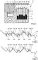
1 einen Schließzylinder mit einem darin eingeführten Schlüssel,2 vergrößert einen Teilbereich des Schlüssels aus1 ,3 eine weitere Ausführungsform des Schlüssels aus2 ,4 einen Teilbereich einer weiteren Ausführungsform des Schlüssels,5 stark vergrößert einen Teilbereich einer Schließausnehmung des Schlüssels aus4 .
1 a lock cylinder with a key inserted therein,2 enlarges a part of thekey 1 ,3 another embodiment of thekey 2 ,4th a part of another embodiment of the key,5 greatly enlarged a partial area of a locking recess of the key4th .
Die Schließausnehmungen
ZITATE ENTHALTEN IN DER BESCHREIBUNG QUOTES INCLUDED IN THE DESCRIPTION
Diese Liste der vom Anmelder aufgeführten Dokumente wurde automatisiert erzeugt und ist ausschließlich zur besseren Information des Lesers aufgenommen. Die Liste ist nicht Bestandteil der deutschen Patent- bzw. Gebrauchsmusteranmeldung. Das DPMA übernimmt keinerlei Haftung für etwaige Fehler oder Auslassungen.This list of the documents listed by the applicant was generated automatically and is included solely for the better information of the reader. The list is not part of the German patent or utility model application. The DPMA assumes no liability for any errors or omissions.
Zitierte PatentliteraturPatent literature cited
- WO 2015/114172 A1 [0002]WO 2015/114172 A1 [0002]
- EP 2281985 A2 [0003]EP 2281985 A2 [0003]
- DE 29818143 U1 [0004]DE 29818143 U1 [0004]
Claims (9)
Translated fromGermanPriority Applications (9)
| Application Number | Priority Date | Filing Date | Title |
|---|---|---|---|
| DE102019201995.1ADE102019201995A1 (en) | 2019-02-14 | 2019-02-14 | KEYS FOR A LOCKING CYLINDER |
| EP20154080.4AEP3696352B1 (en) | 2019-02-14 | 2020-01-28 | Key for a locking cylinder |
| PL20154080.4TPL3696352T3 (en) | 2019-02-14 | 2020-01-28 | Key for a locking cylinder |
| HUE20154080AHUE069321T2 (en) | 2019-02-14 | 2020-01-28 | Key for a locking cylinder |
| ES20154080TES3000059T3 (en) | 2019-02-14 | 2020-01-28 | Key for a locking cylinder |
| FIEP20154080.4TFI3696352T3 (en) | 2019-02-14 | 2020-01-28 | KEY FOR LOCK CYLINDER |
| HRP20241727TTHRP20241727T1 (en) | 2019-02-14 | 2020-01-28 | LOCK CYLINDER KEY |
| DK20154080.4TDK3696352T3 (en) | 2019-02-14 | 2020-01-28 | KEY TO A LOCK CYLINDER |
| SI202030545TSI3696352T1 (en) | 2019-02-14 | 2020-01-28 | Key for a locking cylinder |
Applications Claiming Priority (1)
| Application Number | Priority Date | Filing Date | Title |
|---|---|---|---|
| DE102019201995.1ADE102019201995A1 (en) | 2019-02-14 | 2019-02-14 | KEYS FOR A LOCKING CYLINDER |
Publications (1)
| Publication Number | Publication Date |
|---|---|
| DE102019201995A1true DE102019201995A1 (en) | 2020-08-20 |
Family
ID=69374221
Family Applications (1)
| Application Number | Title | Priority Date | Filing Date |
|---|---|---|---|
| DE102019201995.1AWithdrawnDE102019201995A1 (en) | 2019-02-14 | 2019-02-14 | KEYS FOR A LOCKING CYLINDER |
Country Status (9)
| Country | Link |
|---|---|
| EP (1) | EP3696352B1 (en) |
| DE (1) | DE102019201995A1 (en) |
| DK (1) | DK3696352T3 (en) |
| ES (1) | ES3000059T3 (en) |
| FI (1) | FI3696352T3 (en) |
| HR (1) | HRP20241727T1 (en) |
| HU (1) | HUE069321T2 (en) |
| PL (1) | PL3696352T3 (en) |
| SI (1) | SI3696352T1 (en) |
Family Cites Families (7)
| Publication number | Priority date | Publication date | Assignee | Title |
|---|---|---|---|---|
| DE1813821A1 (en)* | 1968-12-11 | 1970-07-02 | Eaton Yale & Towne Gmbh | Key for lock cylinder |
| DE29818143U1 (en) | 1998-10-10 | 2000-02-17 | Bks Gmbh, 42549 Velbert | Security key |
| DE102004009166B4 (en)* | 2004-02-25 | 2009-10-22 | Aug. Winkhaus Gmbh & Co. Kg | Key for a lock cylinder |
| AT506700B1 (en)* | 2008-07-15 | 2009-11-15 | Evva Werke | FLAT KEY |
| AT508869B1 (en) | 2009-08-06 | 2013-07-15 | Evva Sicherheitstechnologie | KEY AND CYLINDER LOCK |
| DE102015101547A1 (en) | 2014-02-03 | 2015-08-06 | Huf Hülsbeck & Fürst Gmbh & Co. Kg | Locking cylinder for a lock device |
| AT519857B1 (en)* | 2017-04-11 | 2021-04-15 | Evva Sicherheitstechnologie | Key and cylinder lock |
- 2019
- 2019-02-14DEDE102019201995.1Apatent/DE102019201995A1/ennot_activeWithdrawn
- 2020
- 2020-01-28EPEP20154080.4Apatent/EP3696352B1/enactiveActive
- 2020-01-28HRHRP20241727TTpatent/HRP20241727T1/enunknown
- 2020-01-28ESES20154080Tpatent/ES3000059T3/enactiveActive
- 2020-01-28PLPL20154080.4Tpatent/PL3696352T3/enunknown
- 2020-01-28DKDK20154080.4Tpatent/DK3696352T3/enactive
- 2020-01-28SISI202030545Tpatent/SI3696352T1/enunknown
- 2020-01-28FIFIEP20154080.4Tpatent/FI3696352T3/enactive
- 2020-01-28HUHUE20154080Apatent/HUE069321T2/enunknown
Also Published As
| Publication number | Publication date |
|---|---|
| HRP20241727T1 (en) | 2025-02-28 |
| FI3696352T3 (en) | 2024-12-10 |
| DK3696352T3 (en) | 2024-12-09 |
| ES3000059T3 (en) | 2025-02-27 |
| EP3696352B1 (en) | 2024-10-30 |
| HUE069321T2 (en) | 2025-03-28 |
| EP3696352A1 (en) | 2020-08-19 |
| PL3696352T3 (en) | 2025-01-13 |
| SI3696352T1 (en) | 2025-02-28 |
Similar Documents
| Publication | Publication Date | Title |
|---|---|---|
| DE69920530T3 (en) | Key for a cylinder lock | |
| DE4201936C2 (en) | Magnetic card lock | |
| DE202018103312U1 (en) | Insertion element and having this locking device | |
| DE1678125A1 (en) | Key-lock combination with magnetic locking | |
| DE3517660A1 (en) | SAFETY LOCK | |
| DE2559549C3 (en) | Cylinder core with tumbler plate | |
| EP3092359B1 (en) | Cylinder lock | |
| DE102010012261A1 (en) | locking system | |
| EP3696351B1 (en) | Key for a cylinder lock | |
| DE102019201995A1 (en) | KEYS FOR A LOCKING CYLINDER | |
| DE102013103790A1 (en) | Coding via locking bar | |
| DE102019201997A1 (en) | LOCKING DEVICE WITH A KEY AND A LOCKING CYLINDER | |
| EP1746226B1 (en) | Key | |
| EP1577469B1 (en) | Key | |
| AT378811B (en) | CYLINDLE LOCK WITH CYLINDER HOUSING AND A CYLINDER CORE AND FLAT KEY | |
| EP2149657B1 (en) | Key for a lock cylinder and blank for such a key | |
| AT525454B1 (en) | Key for a cylinder lock and cylinder lock | |
| DE102022212579A1 (en) | Lock cylinder | |
| DE102007000177A1 (en) | lock cylinder | |
| DE2442681A1 (en) | Probe-safe cylinder lock - has tumble pins without guide channels, laterally penetrating cylinder | |
| DE102020100925A1 (en) | Lock and cylinder lock with anti-lock picking function | |
| DE60205207T2 (en) | High security locking device and unlocking procedure | |
| DE2800539A1 (en) | Key operated multiple tumbler lock - has additional stops checking bolt if stop or swivel bearing is removed | |
| DE102021123514A1 (en) | Set with lock with cylinder insert and key for this lock | |
| AT511401B1 (en) | CYLINDER LOCK WITH MULTIPLE HOUSING PENCIL |
Legal Events
| Date | Code | Title | Description |
|---|---|---|---|
| R119 | Application deemed withdrawn, or ip right lapsed, due to non-payment of renewal fee |