DE102019135870A1 - Projectile and ammunition - Google Patents
Projectile and ammunitionDownload PDFInfo
- Publication number
- DE102019135870A1 DE102019135870A1DE102019135870.1ADE102019135870ADE102019135870A1DE 102019135870 A1DE102019135870 A1DE 102019135870A1DE 102019135870 ADE102019135870 ADE 102019135870ADE 102019135870 A1DE102019135870 A1DE 102019135870A1
- Authority
- DE
- Germany
- Prior art keywords
- projectile
- recess
- base
- notch
- sacrificial section
- Prior art date
- Legal status (The legal status is an assumption and is not a legal conclusion. Google has not performed a legal analysis and makes no representation as to the accuracy of the status listed.)
- Ceased
Links
Images


Classifications
- F—MECHANICAL ENGINEERING; LIGHTING; HEATING; WEAPONS; BLASTING
- F42—AMMUNITION; BLASTING
- F42B—EXPLOSIVE CHARGES, e.g. FOR BLASTING, FIREWORKS, AMMUNITION
- F42B12/00—Projectiles, missiles or mines characterised by the warhead, the intended effect, or the material
- F42B12/02—Projectiles, missiles or mines characterised by the warhead, the intended effect, or the material characterised by the warhead or the intended effect
- F42B12/04—Projectiles, missiles or mines characterised by the warhead, the intended effect, or the material characterised by the warhead or the intended effect of armour-piercing type
- F42B12/06—Projectiles, missiles or mines characterised by the warhead, the intended effect, or the material characterised by the warhead or the intended effect of armour-piercing type with hard or heavy core; Kinetic energy penetrators
- F—MECHANICAL ENGINEERING; LIGHTING; HEATING; WEAPONS; BLASTING
- F42—AMMUNITION; BLASTING
- F42B—EXPLOSIVE CHARGES, e.g. FOR BLASTING, FIREWORKS, AMMUNITION
- F42B12/00—Projectiles, missiles or mines characterised by the warhead, the intended effect, or the material
- F42B12/72—Projectiles, missiles or mines characterised by the warhead, the intended effect, or the material characterised by the material
- F42B12/74—Projectiles, missiles or mines characterised by the warhead, the intended effect, or the material characterised by the material of the core or solid body
Landscapes
- Engineering & Computer Science (AREA)
- Chemical & Material Sciences (AREA)
- Combustion & Propulsion (AREA)
- General Engineering & Computer Science (AREA)
- Physics & Mathematics (AREA)
- Thermal Sciences (AREA)
- Aiming, Guidance, Guns With A Light Source, Armor, Camouflage, And Targets (AREA)
Abstract
Translated fromGerman
Description
Translated fromGermanDie vorliegende Erfindung betrifft ein Projektil, insbesondere einen Penetrator, für Munition vorzugsweise mit einem Kaliber von weniger als 40 mm, oder einem Kaliber von weniger als 8 mm, wie Kleinkaliber. Gattungsgemäße Projektile werden vorzugsweise im militärischen Bereich eingesetzt und dienen dazu, stärkere sogenannte Schutzklassen zu durchdringen. Dies bedeutet, dass die Projektile in der Lage sind, erhöhte Durchschlagsleistungen zu erzielen, um Ziele erhöhter Festigkeit zu beschädigen. Solche Projektile sind beispielsweise als anti-material rifle (AMR) im englischsprachigen Raum bekannt und dienen zur Bekämpfung gepanzerter oder sich hinter Deckungen befindlicher Objekte, wie Helikopter, gepanzerter Fahrzeuge, Flugzeuge, Schiffe oder dergleichen.The present invention relates to a projectile, in particular a penetrator, for ammunition, preferably with a caliber of less than 40 mm, or a caliber of less than 8 mm, such as small caliber. Generic projectiles are preferably used in the military sector and serve to penetrate stronger so-called protection classes. This means that the projectiles are able to achieve increased penetration rates in order to damage targets of increased strength. Such projectiles are known, for example, as anti-material rifle (AMR) in English-speaking countries and are used to combat armored objects or objects located behind cover, such as helicopters, armored vehicles, aircraft, ships or the like.
Gattungsgemäße Projektile sind beispielsweise aus
An solchen bekannten Projektilen hat sich als nachteilig erwiesen, dass der radial vorstehende Absatz als Bruchstelle wirkt, die eine undefinierte und unkontrollierte Deformation und/oder Fragmentierung des Projektils bewirkt. Beim Einschlagen des Projektils in einem Ziel, insbesondere beim Penetrationsvorgang, hat dies eine reduzierte Durchschlagsleistung zur Folge.In such known projectiles it has been found to be disadvantageous that the radially protruding shoulder acts as a break point, which causes an undefined and uncontrolled deformation and / or fragmentation of the projectile. When the projectile hits a target, in particular during the penetration process, this results in a reduced penetration performance.
Es ist daher Aufgabe der vorliegenden Erfindung, die Nachteile aus dem bekannten Stand der Technik zu verbessern, insbesondere ein Projektil, vorzugsweise einen Penetrator, für Munition bzw. Munition mit verbesserter Durchschlagsleitung bereitzustellen, insbesondere ohne die Kosten des Projektils zu erhöhen.It is therefore the object of the present invention to improve the disadvantages of the known prior art, in particular to provide a projectile, preferably a penetrator, for ammunition or ammunition with an improved penetration line, in particular without increasing the cost of the projectile.
Die Aufgabe wir durch den Gegenstand von Anspruch 1, 3, 7 bzw. 17 gelöst.The object is achieved by the subject matter of
Danach ist ein Projektil, insbesondere Penetrator, vorzugsweise mit einem Kaliber von weniger als 40 mm, insbesondere von weniger als 8 mm, wie Kleinkaliber, für Munition bereitgestellt. Gattungsgemäße Projektile, insbesondere die Penetratoren, insbesondere für panzerbrechende Munition (Im englischen Sprachgebrauch als Armour-Piercing, kurz AP, bezeichnet), dienen dazu, erhöhte Durchschlagsleistungen im Ziel zu erzielen, beispielsweise um im militärischen Bereich stärkere sogenannte Schutzklassen zu durchdringen. Gattungsgemäße Projektile erreichen mindestens Schutzklasse 12, vorzugsweise Schutzklasse 13, gemäß VPAM Standard APR 2006 Edition. Beispielsweise kann das Projektil ein API-Geschoss sein (Armor Piercing, Incendiary), bei dem einem AP-Geschoss ein entzündlicher Stoff (zum Beispiel Zirconium) zugesetzt wird, um einen zusätzlichen Brandeffekt nach dem Durchdringen beispielsweise einer Panzerung zu erzeugen.According to this, a projectile, in particular a penetrator, preferably with a caliber of less than 40 mm, in particular less than 8 mm, such as small caliber, is provided for ammunition. Generic projectiles, especially penetrators, especially for armor-piercing ammunition (referred to as armor piercing, AP for short), are used to achieve increased penetration rates in the target, for example to penetrate stronger so-called protection classes in the military sector. Generic projectiles achieve at least protection class 12, preferably
Das Projektil umfasst einen bugseitigen, insbesondere ogivenförmigen, Opferabschnitt und eine daran anschließende Projektilbasis. Wenn in der vorliegenden Beschreibung von Bug bzw. bugseitig oder Heck bzw. heckseitig gesprochen wird, sind die entsprechenden Bezeichnungen in Hinblick auf eine Flugrichtung des Projektils bzw. im Hinblick auf dessen Orientierung im Schusswaffenlauf zu verstehen, wobei der Projektilbug bezogen auf die Flugrichtung vorne, also frontseitig, angeordnet ist und das Heck bezogen auf die Flugrichtung hinten. Die Projektilbasis ist beispielsweise im Wesentlichen vollständig zylindrisch geformt und/oder aus Vollmaterial gebildet.The projectile comprises a bow-side, in particular ogive-shaped, sacrificial section and an adjoining projectile base. If the present description speaks of bow or bow side or stern or stern side, the corresponding terms are to be understood with regard to a direction of flight of the projectile or with regard to its orientation in the gun barrel, whereby the projectile bow relates to the direction of flight at the front, so on the front, is arranged and the stern is based on the direction of flight behind. The projectile base is, for example, essentially completely cylindrical in shape and / or formed from solid material.
Gemäß einem ersten Aspekt der vorliegenden Erfindung ist/sind ein Übergang zwischen der Projektilbasis und dem bugseitigen Opferabschnitt und/oder die Projektilbasis derart außenseitig gekerbt, dass bei einem Aufprall auf ein Standardziel zumindest teilweise ein Trennen des Opferabschnitts von der Projektilbasis einhergeht. Als Standardziel kann ein vordefiniertes Stahlblech mit vorbestimmter Härte, nämlich 367 Brinell (HB), und vorgegebener Dicke, nämlich 13 mm, hergezogen werden. Das Standardziel kann in einem Standard-Versuchsaufbau verwendet werden, der wie folgt aussieht: Das Projektil wird mittels einer Schusswaffe mit einer Abschussgeschwindigkeit von etwa 880 m/s abgefeuert, sodass es auf das etwa 900 m entfernte Standardziel im Wesentlichen orthogonal auf dessen Zielfläche auftrifft.According to a first aspect of the present invention, a transition between the projectile base and the bow-side sacrificial section and / or the projectile base is notched on the outside in such a way that the sacrificial section is at least partially separated from the projectile base in the event of an impact on a standard target. A predefined steel sheet with a predetermined hardness, namely 367 Brinell (HB), and a predetermined thickness, namely 13 mm, can be used as a standard target. The standard target can be used in a standard test setup, which looks as follows: The projectile is fired by means of a firearm at a launch speed of about 880 m / s, so that it hits the standard target, which is about 900 m away, essentially orthogonally on its target surface.
Zur Erhöhung der Durchschlagsleistung bzw. Penetrationswirkung von Projektilen stellen sich insbesondere die folgenden Herausforderungen dar: in der Regel ist ein Kompromiss aus Kosten, insbesondere Materialkosten für Werkstoffe hoher Dichte und Härte, und Penetrationswirkung sowie ein Kompromiss aus Aerodynamik und Penetrationswirkung zu finden. Durch die erfindungsgemäßen, konstruktiven Maßnahmen konnten die Erfinder der vorliegenden Erfindung die oben genannten Kompromisse dahingehend lösen, dass hohe Penetrationswirkungen erzielt werden können, ohne dass die Kosten des Projektils gestiegen sind und/oder ohne dass auf teure Materialien zurückgegriffen werden muss und/oder ohne die Aerodynamik zu beeinträchtigen. Beispielsweise kann das Projektil aus Stahl hergestellt werden, womit bislang bekannte Projektile ähnlicher Penetrationswirkung nur mit erhöhten Kosten für teure Werkstoffe und/oder verringerter Aerodynamik und damit verringerter Präzision und/oder Flugreichweite hergestellt werden konnten.In order to increase the penetration performance or penetration effect of projectiles, the following challenges in particular arise: as a rule, a compromise has to be found between costs, in particular material costs for materials of high density and hardness, and penetration effect, as well as a compromise between aerodynamics and penetration effect. By means of the constructive measures according to the invention, the inventors of the present invention were able to solve the above-mentioned compromises to the effect that high penetration effects can be achieved without increasing the costs of the projectile and / or without increasing expensive materials must be used and / or without compromising aerodynamics. For example, the projectile can be made of steel, with which previously known projectiles with a similar penetration effect could only be produced with increased costs for expensive materials and / or reduced aerodynamics and thus reduced precision and / or flight range.
Durch das wenigstens teilweise Abtrennen des Opferabschnitts von der Projektilbasis nach dem Auftreffen des Projektils auf das Ziel, insbesondere das vollständige Abtrennen des Opferabschnitts von der Projektilbasis, wird erzielt, dass in Folge des Aufpralls in den Opferabschnitt eingeleitete Schock- und Impulswellen, welche zu einem Versagen und/oder unkontrolliertem Deformieren, insbesondere zu Rissen innerhalb des Projektilmaterials, führen kann, größtenteils durch den Opferabschnitt aufgenommen und absorbiert werden, sodass gewährleistet wird, dass die Projektilbasis im Wesentlichen unversehrt bleibt und nach dem Abtrennen des Opferabschnitts im Wesentlichen unversehrt weiter penetrieren kann. Durch das Gestalten der Kerbe derart, dass sich der Opferabschnitt zuverlässig abtrennt, kann die Penetrationsleistung von Projektilen signifikant gesteigert werden.Through the at least partial separation of the sacrificial section from the projectile base after the projectile has hit the target, in particular the complete separation of the sacrificial section from the projectile base, it is achieved that shock and impulse waves introduced into the sacrificial section as a result of the impact, which lead to failure and / or uncontrolled deformation, in particular to cracks within the projectile material, can be largely taken up and absorbed by the sacrificial section, so that it is ensured that the projectile base remains essentially intact and can continue to penetrate essentially intact after the sacrificial section has been severed. By designing the notch in such a way that the sacrificial section reliably separates, the penetration performance of projectiles can be significantly increased.
Gemäß einer beispielhaften Ausführung des erfindungsgemäßen Projektils sind der Opferabschnitt und Projektilbasis aus einem Stück hergestellt. Beispielsweise kann das Projektil durch Zerspanen, wie Drehen, oder durch Umformen, insbesondere Zugdruckumformen, wie Tiefziehen, hergestellt sein. Das einteilige Projektil wird durch das Vorsehen der umlaufenden Kerbung oder Vertiefung funktionell in ein zweiteiliges Projektil umgewandelt, nämlich den bugseitigen, die Schockwellen und den Energieeintrag aufnehmenden Opferabschnitt und die heckseitige, den Penetrationsvorgang durchführende Projektilbasis. Denn es wurde herausgefunden, dass durch das Bereitstellen und Ausbilden einer gezielten und definierten Sollbruchstelle in Form der umlaufenden Kerbung oder Vertiefung das Deformationsverhalten des Projektils beeinflusst, insbesondere eingestellt, werden kann.According to an exemplary embodiment of the projectile according to the invention, the sacrificial section and projectile base are made in one piece. For example, the projectile can be produced by machining, such as turning, or by forming, in particular tensile compression forming, such as deep drawing. The one-piece projectile is functionally converted into a two-piece projectile by providing the circumferential notch or recess, namely the bow-side, the shock waves and the energy input absorbing sacrificial section and the rear-side projectile base performing the penetration process. It has been found that by providing and forming a targeted and defined predetermined breaking point in the form of the circumferential notch or recess, the deformation behavior of the projectile can be influenced, in particular adjusted.
Gemäß einem weiteren Aspekt der vorliegenden Erfindung, der mit den vorhergehenden Aspekten und beispielhaften Ausführungen kombinierbar ist, ist ein Projektil, insbesondere ein Penetrator, vorzugsweise mit einem Kaliber von weniger als 40 mm, insbesondere von weniger als 8 mm, wie Kleinkaliber, für Munition bereitgestellt.According to a further aspect of the present invention, which can be combined with the preceding aspects and exemplary embodiments, a projectile, in particular a penetrator, preferably with a caliber of less than 40 mm, in particular less than 8 mm, such as small caliber, is provided for ammunition .
Das Projektil umfasst einen bugseitigen, insbesondere ogivenförmigen, Opferabschnitt und eine daran anschließende Projektilbasis. Am Übergang zwischen dem Opferabschnitt und der Projektilbasis und/oder an der Projektilbasis ist eine umlaufende Vertiefung ausgebildet, die zwei gegenüberliegende Vertiefungsflanken und einen die Vertiefungsflanken verbindenden Vertiefungsgrund besitzt. Dabei begrenzen die Vertiefungsflanken die Vertiefung in Bezug auf die Geschosslängsrichtung.The projectile comprises a bow-side, in particular ogive-shaped, sacrificial section and an adjoining projectile base. At the transition between the sacrificial section and the projectile base and / or on the projectile base, a circumferential depression is formed which has two opposite depression flanks and a depression base connecting the depression flanks. The recess flanks limit the recess in relation to the longitudinal direction of the storey.
Gemäß dem weiteren Aspekt der vorliegenden Erfindung ist am Vertiefungsgrund wenigstens ein Profilsprung vorgesehen. Mit anderen Worten springt wenigstens eine der beiden Vertiefungsflanken am Vertiefungsgrund zurück in Richtung Projektilaußenseite, die beispielsweise durch einen Opferabschnittmantel oder einen Projektilbasismantel gebildet sein kann, je nachdem, in welcher Position bezüglich der Längsrichtung sich die Vertiefung befindet. Beispielsweise kann die Vertiefung im Querschnitt eine V-Form besitzen, wobei am Vertiefungsgrund ein einziger Profilsprung ausgebildet ist. Die Vertiefung kann beispielsweise auch eine U-Form im Querschnitt besitzen, sodass am Vertiefungsgrund zwei Profilsprünge realisiert sind, nämlich jeweils zwischen Vertiefungsgrund und je einer benachbarten Vertiefungsflanke, die somit jeweils ausgehend vom Vertiefungsgrund zurück zu dem jeweiligen Mantelabschnitt springen. Durch die erfindungsgemäße Gestaltung der Vertiefung wird eine klar definierte Sollbruchstelle generiert, welche die Penetrationswirkung des Projektils signifikant steigert. Die Erfinder der vorliegenden Erfindung haben herausgefunden, dass sich der Profilsprung am Vertiefungsgrund in Form einer Rissbremse bemerkbar macht und nach einem Aufprall des Projektils auf ein Ziel in den Opferabschnitt eingeleitete Risse nadelöhrartig fokussiert und ein Ausbreiten der Risse in die Projektilbasis verhindert. Ferner wird die Fähigkeit der Vertiefung, in den Opferabschnitt eingeleitete Schock- und Impulswellen nach einem Aufprall des Projektils aufzufangen bzw. dessen Ausbreitung in die Projektilbasis zu unterbinden, deutlich verstärkt. Somit ermöglicht auch die Vertiefungsgestaltung gemäß dem zweiten erfindungsgemäßen Aspekt eine deutlich erhöhte Penetrationswirkung sowie einen Schutz der Projektilbasis, damit diese für den nach dem Aufprall des Projektils erfolgenden Penetrationsvorgang im Wesentlichen unversehrt verbleibt.According to the further aspect of the present invention, at least one profile step is provided at the bottom of the depression. In other words, at least one of the two recess flanks on the recess base jumps back towards the outside of the projectile, which can be formed, for example, by a sacrificial section jacket or a projectile base jacket, depending on the position in which the recess is located in relation to the longitudinal direction. For example, the recess can have a V-shape in cross-section, a single profile step being formed at the bottom of the recess. The recess can, for example, also have a U-shape in cross section, so that two profile jumps are implemented at the base of the recess, namely each between the base of the recess and an adjacent recess flank, which thus jump back to the respective shell section starting from the base of the recess. The design of the recess according to the invention generates a clearly defined predetermined breaking point which significantly increases the penetration effect of the projectile. The inventors of the present invention have found that the profile jump at the bottom of the recess becomes noticeable in the form of a crack brake and that after the projectile has hit a target, it focuses cracks introduced into the sacrificial section like a needle eye and prevents the cracks from spreading into the projectile base. Furthermore, the ability of the depression to absorb shock waves and impulse waves introduced into the victim section after the projectile has hit or to prevent its propagation into the projectile base is significantly increased. Thus, the recess design according to the second aspect of the invention also enables a significantly increased penetration effect and protection of the projectile base so that it remains essentially undamaged for the penetration process that takes place after the impact of the projectile.
Beispielsweise ist eine der Vertiefungsflanken, insbesondere die opferabschnittseitige Vertiefungsflanke, im Wesentlichen lotrecht bezüglich einer Längsachse des Projektils orientiert. Die andere der beiden Vertiefungsflanken, insbesondere die bugseitige Vertiefungsflanke, ist zur Bildung der Vertiefung in einem Winkel bezüglich der Längsachse und bezüglich der jeweils anderen Vertiefungsflanke orientiert. Mit anderen Worten kann die Vertiefung derart gestaltet sein, dass eine opferabschnittseitige Vertiefungsflanke im Wesentlichen lotrecht bezüglich eines angrenzenden Opferabschnittmantels und eine bugseitige Vertiefungsflanke sowohl bezüglich der opferabschnittseitigen Vertiefungsflanke als auch bezüglich eines angrenzenden Projektilbasismantels geneigt ist.For example, one of the depression flanks, in particular the depression flank on the victim section, is oriented essentially perpendicularly with respect to a longitudinal axis of the projectile. The other of the two depression flanks, in particular the bow-side depression flank, is oriented at an angle with respect to the longitudinal axis and with respect to the respective other depression flank in order to form the depression. In other words, the depression can be designed in such a way that a depression flank on the victim section side is essentially perpendicular with respect to an adjoining sacrificial section casing and a bow-side depression flank both with respect to the depression flank on the victim section is inclined with respect to an adjacent projectile base mantle.
Gemäß einer beispielhaften Weiterbildung des erfindungsgemäßen Projektils ist die Vertiefung als spitz zulaufende Kerbe realisiert. Die Kerbe weist einen scharfkantigen Kerbgrund mit einem Radius von weniger als 0,8 mm, insbesondere weniger als 0,7 mm, 0,6 mm, 0,5 mm oder weniger als 0,4 mm, auf. Dabei kann der Radius des scharfkantigen Kerbgrunds größer als 0,05 mm sein. Die Scharfkantigkeit des Kerbgrundes hat sich zum einen vorteilhaft in Bezug auf ein zuverlässiges Abtrennen des Opferabschnitts von der Projektilbasis und zum anderen in Bezug auf das Schützen der Projektilbasis als vorteilhaft erwiesen.According to an exemplary development of the projectile according to the invention, the depression is implemented as a tapering notch. The notch has a sharp-edged notch base with a radius of less than 0.8 mm, in particular less than 0.7 mm, 0.6 mm, 0.5 mm or less than 0.4 mm. The radius of the sharp-edged notch base can be greater than 0.05 mm. The sharp edges of the notch base have proven to be advantageous, on the one hand, in relation to reliable separation of the sacrificial portion from the projectile base and, on the other hand, to be advantageous in relation to protecting the projectile base.
Gemäß einer weiteren beispielhaften Ausführung eines erfindungsgemäßen Projektils besitzt die Vertiefung bzw. die Kerbe eine Tiefe ausgehend von einer Mantelfläche des Opferabschnitts und/oder von einer Mantelfläche der Projektilbasis, wobei die jeweilige Mantelfläche den Außendurchmesser des jeweiligen Abschnitts festlegt, im Bereich 5 % bis 50 %, insbesondere im Bereich von 7,5 % bis 40 %, 9 % bis 30 % oder im Bereich von 10 bis 25 % eines Kaliberdurchmessers. Eine signifikante Vertiefungs- bzw. Kerbtiefe in dem oben genannten Bereich verstärkt die oben genannten erfindungsgemäßen vorteilhaften technischen Effekte.According to a further exemplary embodiment of a projectile according to the invention, the recess or the notch has a depth starting from a jacket surface of the sacrificial section and / or from a jacket surface of the projectile base, the respective jacket surface defining the outer diameter of the respective section, in the
Gemäß einer beispielhaften Weiterbildung des erfindungsgemäßen Projektils besitzt die Vertiefung bzw. die Kerbe einen Öffnungswinkel im Bereich von 5° bis 50°, insbesondere im Bereich von 7,5° bis 45° oder im Bereich von 10° bis 40°. Es kann vorgesehen sein, dass die Vertiefung bzw. die Kerbe zwei umlaufende, in einen gemeinsamen Vertiefungs- bzw. Kerbgrund mündende Vertiefungs- bzw. Kerbflanken aufweist. Die Vertiefungs- bzw. die Kerbflanken können in einem Winkel im beanspruchten Bereich, das heißt in dem Bereich von 5° bis 50°, insbesondere im Bereich von 7,5° bis 45° oder im Bereich von 10° bis 40°, zueinander angewinkelt sein. Als Öffnungswinkel kann ein Winkel verstanden werden, welcher durch die zwei gegenüberliegenden, einander zugeordneten Vertiefungs- bzw. Kerbflanken aufgespannt wird.According to an exemplary development of the projectile according to the invention, the recess or the notch has an opening angle in the range from 5 ° to 50 °, in particular in the range from 7.5 ° to 45 ° or in the range from 10 ° to 40 °. It can be provided that the recess or the notch has two circumferential recess or notch flanks opening into a common recess or notch base. The recess or notch flanks can be angled to one another at an angle in the stressed range, that is in the range from 5 ° to 50 °, in particular in the range from 7.5 ° to 45 ° or in the range from 10 ° to 40 ° be. An opening angle can be understood to be an angle which is spanned by the two opposing, mutually associated depression or notch flanks.
Gemäß einem weiteren Aspekt der vorliegenden Erfindung, der mit dem vorhergehenden Aspekten und beispielhaften Ausführungen kombinierbar ist, ist ein Projektil, insbesondere ein Penetrator, vorzugsweise mit einem Kaliber von weniger als 40 mm, insbesondere von weniger als 8 mm, wie Kleinkaliber, für Munition bereitgestellt. Das Projektil umfasst einen bugseitigen, insbesondere ogivenförmigen, Opferabschnitt und eine daran anschließende heckseitige Projektilbasis. Am Übergang zwischen dem Opferabschnitt und der Projektilbasis und/oder an der Projektilbasis ist eine umlaufende Vertiefung ausgebildet.According to a further aspect of the present invention, which can be combined with the preceding aspects and exemplary embodiments, a projectile, in particular a penetrator, preferably with a caliber of less than 40 mm, in particular less than 8 mm, such as small caliber, is provided for ammunition . The projectile comprises a bow-side, in particular ogive-shaped, sacrificial section and an adjoining rear-side projectile base. A circumferential depression is formed at the transition between the sacrificial section and the projectile base and / or on the projectile base.
Gemäß dem weiteren erfindungsgemäßen Aspekt ist die Vertiefung bezüglich der Projektillängsrichtung in Richtung Projektilheck geneigt. Mit anderen Worten können zwei einander gegenüberliegende Vertiefungsflanken, die die Vertiefung in Projektillängsrichtung begrenzen, sowohl eine Radial- als auch eine Axialkomponente aufweisen, wobei insbesondere die projektilbasisseitige bzw. heckseitige Vertiefungsflanke eine größere Axialkomponente besitzt als die opferabschnittsseitige bzw. bugseitige Vertiefungsflanke. Dabei ist unter der Axialrichtung eine in Projektillängsrichtung orientierte Richtung zu verstehen und als Radialrichtung eine bezüglich der Axial- bzw. Projektillängsrichtung quer, insbesondere lotrecht, orientierte Richtung. Das Projektil kann rotationssymmetrisch bezüglich einer Geschossmittelachse, die dann die Axialrichtung festlegt, gestaltet sein und eine Radialrichtung ausgehend von der Geschossmittelachse hin zu einem Außenumfang des Projektils festlegen. Es wurde herausgefunden, dass durch die Neigung der Vertiefung in Richtung Projektilheck sich eine gewünschte Deformation und dabei ein gewünschtes Projektil-Zwischenprodukt, auch Intermediat genannt, ergibt, da die Neigung der Vertiefung zur Folge hat, dass sich der Opferabschnitt wenigstens teilweise entlang der Neigungsrichtung von der Projektilbasis abtrennt und sich somit die Projektilbasis nach der Abtrennung des Opferabschnitts bugseitig zumindest axialabschnittsweise insbesondere konisch verjüngt. Eingeleitete Schock- bzw. Impulswellen können dadurch von der Projektilbasis besser aufgenommen bzw. besser abgeleitet werden, wodurch die Projektilbasis für einen längeren Zeitraum stabil bleibt und daher für einen längeren Zeitraum penetrieren kann. Auch die Vertiefungsgestaltung gemäß dem dritten erfindungsgemäßen Aspekt bewirkt somit eine deutlich erhöhte Penetrationswirkung und/oder einen gesteigerten Schutz der Projektilbasis, damit diese für den nach dem Aufprall des Projektils erfolgenden Penetrationsvorgang im Wesentlichen unversehrt verbleibt.According to the further aspect of the invention, the recess is inclined with respect to the longitudinal direction of the projectile in the direction of the rear of the projectile. In other words, two opposing depression flanks that delimit the depression in the longitudinal direction of the projectile can have both a radial and an axial component, with the projectile base-side or rear-side depression flank in particular having a larger axial component than the victim section-side or bow-side depression flank. Here, the axial direction is to be understood as a direction oriented in the longitudinal direction of the projectile and the radial direction as a direction oriented transversely, in particular perpendicular, with respect to the axial or longitudinal direction of the projectile. The projectile can be designed to be rotationally symmetrical with respect to a central axis of the projectile, which then defines the axial direction, and can define a radial direction starting from the central axis of the projectile towards an outer circumference of the projectile. It was found that the inclination of the recess in the direction of the projectile tail results in a desired deformation and thereby a desired projectile intermediate product, also called intermediate, since the inclination of the recess results in the sacrificial section at least partially along the inclination direction of separates the projectile base and thus the projectile base tapers, in particular conically, at least axially in sections on the bow side after the separation of the sacrificial section. Introduced shock waves or impulse waves can thereby be better absorbed by the projectile base or better derived, whereby the projectile base remains stable for a longer period of time and can therefore penetrate for a longer period of time. The recess design according to the third aspect of the invention thus also brings about a significantly increased penetration effect and / or increased protection of the projectile base so that it remains essentially intact for the penetration process that takes place after the projectile impacts.
Gemäß einer beispielhaften Weiterbildung des erfindungsgemäßen Projektils ist die Vertiefung derart geneigt, dass nach Abtrennung des Opferabschnitts von der Projektilbasis die Projektilbasis im Wesentlichen eine, insbesondere in Flugrichtung weisende, torpedo- oder pfeilartige Form besitzt. Beispielsweise kann sich die Projektilbasis nach Abtrennung des Opferabschnitts bugseitig verjüngen. Die Pfeil- bzw. Torpedoform, insbesondere die bugseitige Verjüngung, des Projektil-Intermediats, welches im Wesentlichen ausschließlich durch die Projektilbasis gebildet ist, kann eine verbesserte Penetrationsleistung erzielen und auftreffende Schock- bzw. Impulswellen besser aufnehmen bzw. besser ableiten.According to an exemplary development of the projectile according to the invention, the recess is inclined in such a way that, after the sacrificial section has been separated from the projectile base, the projectile base essentially has a torpedo or arrow-like shape, in particular pointing in the direction of flight. For example, after the sacrificial section has been separated, the projectile base can taper on the bow side. The arrow or torpedo shape, in particular the bow-side taper, of the projectile intermediate, which is essentially formed exclusively by the projectile base, can achieve improved penetration performance and better absorb or better dissipate impacting shock waves or impulse waves.
In einer weiteren beispielhaften Ausführung eines erfindungsgemäßen Projektils besitzt die Vertiefung bzw. die Kerbe zwei umlaufende in einen gemeinsamen Vertiefungs- bzw. Kerbgrund mündende Vertiefungs- bzw. Kerbflanken. Die Vertiefungs- bzw. Kerbflanken begrenzen die Vertiefung bzw. die Kerbe in Projektillängsrichtung und der Vertiefungs- bzw. Kerbgrund die Vertiefung bzw. die Kerbe quer zur Projektillängsrichtung, insbesondere in Radialrichtung. Es kann vorgesehen sein, dass die projektilbasisseitige, bugseitige Vertiefungs- bzw. Kerbflanke wenigstens abschnittsweise, vorzugsweise vollständig, konvex gekrümmt ist. Es wurde herausgefunden, dass sich durch eine konvex gekrümmte bugseitige Vertiefungs- bzw. Kerbflanke nach Abtrennung des Opferabschnitts von der Projektilbasis das Projektil-Intermediat, welches im Wesentlichen durch die Projektilbasis gebildet ist, noch besser an die die Penetrationsleistung erhöhende Torpedo- bzw. Pfeilform anpasst.In a further exemplary embodiment of a projectile according to the invention, the recess or the notch has two circumferential recess or notch flanks opening into a common recess or notch base. The recess or notch flanks delimit the recess or the notch in the longitudinal direction of the projectile and the recess or notch base delimit the recess or the notch transversely to the longitudinal direction of the projectile, in particular in the radial direction. It can be provided that the projectile base-side, bow-side recess or notch flank is at least partially, preferably completely, convexly curved. It has been found that a convexly curved bow-side recess or notch flank, after the sacrificial section has been separated from the projectile base, adapts the projectile intermediate, which is essentially formed by the projectile base, even better to the torpedo or arrow shape which increases the penetration power .
In einer weiteren beispielhaften Ausführung des erfindungsgemäßen Projektils besitzt die Vertiefung bzw. die Kerbe zwei umlaufende, in einen gemeinsamen Vertiefungs- bzw. Kerbgrund mündende Vertiefungs- bzw. Kerbflanken. Die Vertiefungs- bzw. Kerbflanken besitzen auf radialer Höhe einer Mantelfläche des Opferabschnitts und/oder einer Mantelfläche der Projektilbasis einen in Projektillängs- bzw. Axialrichtung bemessenen Abstand zueinander von wenigstens 2 mm. Der beanspruchte Abstand von wenigstens 2 mm zwischen den Vertiefungs- bzw. Kerbflanken, insbesondere zwischen dessen auf radialer Höhe der entsprechenden Mantelfläche angeordneten Kanten, vermeidet, dass lediglich ein duktiles Verformen des Projektils, insbesondere der beiden Vertiefungs- bzw. Kerbflanken, nach dem Aufprall des Projektils auf das Ziel einhergeht und gewährleistet, dass die gewünschte Deformation, insbesondere der gewünschte Sollbruch, das heißt Abtrennen des Opferabschnitts von der Projektilbasis, erreicht wird.In a further exemplary embodiment of the projectile according to the invention, the recess or the notch has two circumferential recess or notch flanks opening into a common recess or notch base. The recess or notch flanks have at the radial height of a jacket surface of the sacrificial section and / or a jacket surface of the projectile base a spacing from one another of at least 2 mm, measured in the projectile longitudinal or axial direction. The claimed distance of at least 2 mm between the recess or notch flanks, in particular between its edges arranged at the radial height of the corresponding lateral surface, prevents only ductile deformation of the projectile, in particular the two recess or notch flanks, after the impact of the Projectile goes hand in hand with the target and ensures that the desired deformation, in particular the desired breaking, that is, separation of the sacrificial portion from the projectile base, is achieved.
Gemäß einer beispielhaften Weiterbildung des erfindungsgemäßen Projektils ist die Kerbe bzw. die Vertiefung etwa mittig in Bezug auf eine Gesamtlängserstreckung des Projektils positioniert. Beispielsweise ist die Vertiefung bzw. die Kerbe am Übergang zwischen Projektilbasis und Opferabschnitt angeordnet, sodass die Vertiefung bzw. die Kerbe das Projektil etwa mittig in Projektilbasis und Opferabschnitt unterteilt.According to an exemplary development of the projectile according to the invention, the notch or the recess is positioned approximately centrally with respect to an overall longitudinal extent of the projectile. For example, the recess or the notch is arranged at the transition between the projectile base and the sacrificial section, so that the recess or the notch divides the projectile approximately centrally into the projectile base and the sacrificial section.
Gemäß einer weiteren beispielhaften Ausführung des erfindungsgemäßen Projektils befindet sich die Kerbe bzw. die Vertiefung an einem Übergang zwischen Projektilbasis und Opferabschnitt. An dem Übergang zwischen Projektilbasis und Opferabschnitt kann eine Durchmesservergrößerung von der Projektilbasis hin zum Opferabschnitt einhergehen. Der somit in Radialrichtung über die Projektilbasis hervorstehende, insbesondere sich ogivenförmig verjüngende, Opferabschnitt-Kopf wirkt sich zum einen positiv auf die Aerodynamik des Projektils aus und verstärkt im Zusammenhang mit der am Übergang zwischen Projektilbasis und Opferabschnitt angeordneten Vertiefung die Penetrationsleistung des Projektils, insbesondere durch Schützen der Projektilbasis. Die Durchmesservergrößerung der Projektilbasis hin zum Opferabschnitt kann unter Bildung eines stufenförmigen oder kontinuierlich zunehmenden Absatzes realisiert sein.According to a further exemplary embodiment of the projectile according to the invention, the notch or the depression is located at a transition between the projectile base and the sacrificial section. At the transition between the projectile base and the sacrificial section, there may be an increase in diameter from the projectile base to the sacrificial section. The sacrificial section head that protrudes in the radial direction over the projectile base, in particular tapering in the shape of an ogive, has a positive effect on the aerodynamics of the projectile and, in connection with the recess located at the transition between the projectile base and the sacrificial section, increases the penetration performance of the projectile, in particular by shooters the projectile base. The enlargement of the diameter of the projectile base towards the sacrificial section can be realized with the formation of a step-shaped or continuously increasing shoulder.
Gemäß einer beispielhaften Weiterbildung des erfindungsgemäßen Projektils sind wenigstens zwei Kerben bzw. Vertiefungen insbesondere gleichmäßig entlang der Gesamtlängserstreckung des Projektils verteilt, beispielsweise bei einem Drittel bzw. zwei Drittel in Bezug auf die Längserstreckung des Projektils angeordnet. Dabei kann vorgesehen sein, dass die zwei Kerben bzw. zwei Vertiefungen formgleich gebildet sind, insbesondere mittels desselben Werkzeugs, wie Einstechwerkzeugs, hergestellt.According to an exemplary development of the projectile according to the invention, at least two notches or depressions are in particular evenly distributed along the total longitudinal extent of the projectile, for example arranged at a third or two thirds in relation to the longitudinal extent of the projectile. It can be provided that the two notches or two depressions are formed with the same shape, in particular produced by means of the same tool as the piercing tool.
In einer weiteren beispielhaften Ausführung des erfindungsgemäßen Projektils ist das Projektil aus Metall, wie Stahl, Eisen, gehärtetem Stahl, Hartmetall oder Wolfram, hergestellt. Dabei ist klar, dass die härteren Werkstoffe höherer Dichte sich noch positiver auf die Penetrationsleistung auswirken, jedoch kostenintensiver sein können. Durch die erfindungsgemäßen konstruktiven Ausgestaltungen der Kerbe bzw. der Vertiefung erfindungsgemäßer Projektile wurde erreicht, dass trotz der Verwendung kostengünstiger, weniger harten Werkstoffe trotzdem eine signifikante Erhöhung der Penetrationswirkung erzielt wird.In a further exemplary embodiment of the projectile according to the invention, the projectile is made of metal such as steel, iron, hardened steel, hard metal or tungsten. It is clear that the harder materials of higher density have an even more positive effect on the penetration performance, but can be more cost-intensive. As a result of the structural designs according to the invention of the notch or the recess of projectiles according to the invention, it was achieved that despite the use of less expensive, less hard materials, a significant increase in the penetration effect is achieved.
Gemäß einer beispielhaften Weiterbildung des erfindungsgemäßen Projektils ist die Kerbe bzw. die Vertiefung derart positioniert und/oder dimensioniert, dass beim Auftreffen des Projektils auf ein Ziel die Kerbe bzw. die Vertiefung ein Ausbreiten von Schockwellen von dem Opferabschnitt in die Projektilbasis unterbindet. Die in Folge des Aufpralls des Projektils auf ein Ziel in den bugseitigen Opferabschnitt eingeleiteten Schockwellen können nicht ungehindert in die Projektilbasis eingeleitet werden, sondern werden durch die Vertiefung bzw. die Kerbe an der Ausbreitung gehindert, insbesondere nadelöhrartig konzentriert. Dadurch wird die Schockwellenenergie in dem Opferabschnitt fokussiert und von der Projektilbasis im Wesentlichen ferngehalten, die somit im Wesentlichen unversehrt bleiben und maximale Energie zur Penetration des Ziels bereitstellen kann. Alternativ oder zusätzlich kann die Kerbe bzw. die Vertiefung derart positioniert und/oder dimensioniert sein, dass beim Auftreffen des Projektils auf ein Ziel die Kerbe bzw. die Vertiefung ein Ausbreiten von in den Opferabschnitt eingeleiteten Rissen in die Projektilbasis unterbindet. Beispielsweise fungiert die Kerbe bzw. die Vertiefung als Risssenke bzw. Rissbremse. Sich in dem Opferabschnitt ausbildende Risse werden an der Kerbe bzw. der Vertiefung aufgehalten und dort kanalisiert, insbesondere in Form eines Nadelöhrs, um somit die Ausbreitung der Risse in die Projektilbasis zu vermeiden, sodass diese im Wesentlichen unversehrt bleiben kann. Alternativ oder zusätzlich kann die Vertiefung bzw. die Kerbe derart positioniert und/oder dimensioniert sein, dass beim Auftreffen des Projektils auf ein Ziel die Kerbe bzw. die Vertiefung eine Impulsübertragung von dem Opferabschnitt in die Projektilbasis unterbindet. Insbesondere ist vorgesehen, dass die Kerbe bzw. die Vertiefung die Impulse zurück in den Opferabschnitt in Richtung Projektilbug reflektiert. Eine Ausbreitung der Impulse in die Projektilbasis kann unterbunden und die Projektilbasis damit geschützt werden.According to an exemplary development of the projectile according to the invention, the notch or the recess is positioned and / or dimensioned in such a way that when the projectile strikes a target, the notch or the recess prevents shock waves from spreading from the sacrificial section into the projectile base. The shock waves introduced into the bow-side sacrificial section as a result of the projectile hitting a target cannot be introduced unhindered into the projectile base, but are prevented from spreading by the depression or notch, in particular concentrated like a needle eye. As a result, the shock wave energy is focused in the victim section and is essentially kept away from the projectile base, which thus remains essentially intact and can provide maximum energy for penetration of the target. Alternatively or additionally, the notch or the recess can be positioned and / or dimensioned in such a way that when the projectile strikes a target, the notch or the recess causes cracks introduced into the sacrificial section to spread the projectile base prevents. For example, the notch or depression functions as a crack depression or crack brake. Cracks forming in the sacrificial section are held up at the notch or the depression and channeled there, in particular in the form of a needle eye, in order to prevent the cracks from spreading into the projectile base so that it can remain essentially intact. Alternatively or additionally, the recess or the notch can be positioned and / or dimensioned in such a way that when the projectile strikes a target, the notch or the recess prevents impulse transmission from the sacrificial section into the projectile base. In particular, it is provided that the notch or the depression reflects the impulses back into the sacrificial section in the direction of the projectile nose. The impulses can be prevented from spreading into the projectile base and the projectile base can thus be protected.
Gemäß einem weiteren Aspekt der vorliegenden Erfindung, der mit den vorhergehenden Aspekten und beispielhaften Ausführungen kombinierbar ist, ist eine Munition, vorzugsweise mit einem Kaliber von weniger als 40 mm, insbesondere mit einem Kaliber von weniger als 8 mm, wie Kleinkaliber, bereitgestellt, die Munition umfasst einen Projektilschuh, oder einen Projektilmantel, und ein nach einem der vorstehenden Ansprüche ausgebildetes, vorzugsweise in den Projektilschuh bzw. den Projektilmantel eingepresstes, Projektil. Mittels der erfindungsgemäßen Munition lässt sich eine deutlich erhöhte Penetrationswirkung im Vergleich zum im Stand der Technik erhältlichen Munition erzielen, wobei keine Einbußen in Bezug auf eine schlechte Aerodynamik und/oder hohe Kosten gemacht werden müssen.According to a further aspect of the present invention, which can be combined with the preceding aspects and exemplary embodiments, ammunition, preferably with a caliber of less than 40 mm, in particular with a caliber of less than 8 mm, such as small caliber, is provided, the ammunition comprises a projectile shoe, or a projectile casing, and a projectile designed according to one of the preceding claims, preferably pressed into the projectile shoe or the projectile casing. By means of the ammunition according to the invention, it is possible to achieve a significantly increased penetration effect compared to the ammunition available in the prior art, without having to make any losses in terms of poor aerodynamics and / or high costs.
Bevorzugte Ausführungen sind in den Unteransprüchen gegeben.Preferred embodiments are given in the subclaims.
Im Folgenden werden weitere Eigenschaften, Merkmale und Vorteile der Erfindung mittels Beschreibung bevorzugter Ausführungen der Erfindung anhand der beiliegenden beispielhaften Zeichnungen deutlich, in denen zeigen:
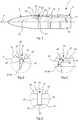
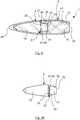
1 eine Schnittansicht einer beispielhaften Ausführung erfindungsgemäßer Munition mit einem erfindungsgemäßen Projektil;2 eine Detailansicht 11 einer Vertiefung desProjektils nach 1 ;3 eine alternative Ausführung einer Vertiefung;4 eine weitere alternative Ausführung einer Vertiefung;5 eine Schnittansicht einer weiteren beispielhaften Ausführung erfindungsgemäßer Munition mit einem erfindungsgemäßen Projektil;6 eine Seitenansicht desProjektils nach 5 ;7 eine Schnittansicht einer weiteren beispielhaften Ausführung erfindungsgemäßer Munition mit einem erfindungsgemäßen Projektil;8 eine Seitenansicht desProjektils nach 7 ;9 eine Schnittansicht einer weiteren beispielhaften Ausführung erfindungsgemäßer Munition mit einem erfindungsgemäßen Projektil; und10 eine Seitenansichtdes Projektils nach 9 .
1 a sectional view of an exemplary embodiment of ammunition according to the invention with a projectile according to the invention;2 adetailed view 11 of a recess in theprojectile 1 ;3 an alternative embodiment of a recess;4th another alternative embodiment of a recess;5 a sectional view of a further exemplary embodiment of ammunition according to the invention with a projectile according to the invention;6th a side view of the projectile according to5 ;7th a sectional view of a further exemplary embodiment of ammunition according to the invention with a projectile according to the invention;8th a side view of the projectile according to7th ;9 a sectional view of a further exemplary embodiment of ammunition according to the invention with a projectile according to the invention; and10 a side view of the projectile according to9 .
In der folgenden Beschreibung beispielhafter Ausführungen erfindungsgemäßer Munition und erfindungsgemäßer Projektile sind eine erfindungsmäße Munition im Allgemeinen mit der Bezugsziffer
In
In dem Hohlraum
Im Bereich des Übergangs von Projektilbasis
In den
Die Kerbe
Die spitz zulaufende Kerbe
Die sacklochbohrungsartige Vertiefung
Anhand der
In
Die Munition
Des Weiteren unterscheidet sich das Projektil
Im Unterschied zu den vorhergehenden Ausführungsformen ist der Führungsschuh zweiteilig gebildet und umfasst einen heckseitigen, den Sitz
Bei der weiteren beispielhaften Ausführung erfindungsgemäßer Munition
Der Mantel
Die in der vorstehenden Beschreibung, den Figuren und den Ansprüchen offenbarten Merkmale können sowohl einzeln als auch in beliebiger Kombination für die Realisierung der Erfindung in den verschiedenen Ausgestaltungen von Bedeutung sein.The features disclosed in the above description, the figures and the claims can be important both individually and in any combination for realizing the invention in the various configurations.
BezugszeichenlisteList of reference symbols
- 11
- Munitionammunition
- 33
- Projektilprojectile
- 55
- ProjektilschuhProjectile shoe
- 77th
- Hohlraumcavity
- 99
- SitzSeat
- 1111
- Bodenground
- 1313th
- ProjektilbasisProjectile base
- 1515th
- OpferabschnittSacrificial section
- 1717th
- AuflageschulterSupport shoulder
- 1919th
- Randedge
- 2121
- Vertiefungdeepening
- 23, 2523, 25
- VertiefungsflankeRecess flank
- 2727
- VertiefungsgrundReason for specialization
- 29, 3129, 31
- ProfilsprungProfile jump
- 3333
- ProfilheckProfile rear
- 3535
- ProjektilbasismantelProjectile base coat
- 3737
- OpferabschnittmantelSacrificial section coat
- 39, 4139, 41
- KanteEdge
- 4545
- BugabschnittBow section
- 4646
- Randedge
- 4747
- Mantelcoat
- 4949
- MunitionsspitzeAmmunition tip
- 5151
- Kerncore
- 5353
- Öffnungopening
- 5555
- ÖffnungswandungOpening wall
- FF.
- FlugrichtungFlight direction
- αα
- ÖffnungswinkelOpening angle
- ββ
- Winkel zwischen opferabschnittseitiger Vertiefungsflanke und LängsachseAngle between the side of the recess on the side of the victim section and the longitudinal axis
- δδ
- Winkel zwischen projektilbasisseitiger Vertiefungsflanke und angrenzender MantelflächeAngle between the recess flank on the projectile base side and the adjacent lateral surface
ZITATE ENTHALTEN IN DER BESCHREIBUNGQUOTES INCLUDED IN THE DESCRIPTION
Diese Liste der vom Anmelder aufgeführten Dokumente wurde automatisiert erzeugt und ist ausschließlich zur besseren Information des Lesers aufgenommen. Die Liste ist nicht Bestandteil der deutschen Patent- bzw. Gebrauchsmusteranmeldung. Das DPMA übernimmt keinerlei Haftung für etwaige Fehler oder Auslassungen.This list of the documents listed by the applicant was generated automatically and is included solely for the better information of the reader. The list is not part of the German patent or utility model application. The DPMA assumes no liability for any errors or omissions.
Zitierte PatentliteraturPatent literature cited
- EP 0279732 B1 [0002]EP 0279732 B1 [0002]
Claims (16)
Translated fromGermanPriority Applications (2)
| Application Number | Priority Date | Filing Date | Title |
|---|---|---|---|
| DE102019135870.1ADE102019135870A1 (en) | 2019-12-30 | 2019-12-30 | Projectile and ammunition |
| EP20215911.7AEP3845853B1 (en) | 2019-12-30 | 2020-12-21 | Projectile and ammunition |
Applications Claiming Priority (1)
| Application Number | Priority Date | Filing Date | Title |
|---|---|---|---|
| DE102019135870.1ADE102019135870A1 (en) | 2019-12-30 | 2019-12-30 | Projectile and ammunition |
Publications (1)
| Publication Number | Publication Date |
|---|---|
| DE102019135870A1true DE102019135870A1 (en) | 2021-07-01 |
Family
ID=73856076
Family Applications (1)
| Application Number | Title | Priority Date | Filing Date |
|---|---|---|---|
| DE102019135870.1ACeasedDE102019135870A1 (en) | 2019-12-30 | 2019-12-30 | Projectile and ammunition |
Country Status (2)
| Country | Link |
|---|---|
| EP (1) | EP3845853B1 (en) |
| DE (1) | DE102019135870A1 (en) |
Families Citing this family (1)
| Publication number | Priority date | Publication date | Assignee | Title |
|---|---|---|---|---|
| WO2025165349A1 (en)* | 2024-01-30 | 2025-08-07 | Sig Sauer, Inc. | Multi-piece projectile |
Citations (7)
| Publication number | Priority date | Publication date | Assignee | Title |
|---|---|---|---|---|
| DE1240760B (en)* | 1962-12-24 | 1967-05-18 | Diehl Fa | Tank incendiary bullet |
| DE3031722A1 (en)* | 1980-08-23 | 1986-10-09 | Rheinmetall GmbH, 4000 Düsseldorf | BALANCE SHOOTING ARRANGEMENT WITH TOP-SIDED DRIVE CAGE |
| DE3031723A1 (en)* | 1980-03-27 | 1989-01-19 | Rheinmetall Gmbh | Armour piercing shell with sub-calibre penetrator - has preset number of break-up points and spacing of distal break-up groove for coupling penetrator sections |
| DE3932952A1 (en)* | 1989-10-03 | 1991-04-11 | Rheinmetall Gmbh | BULLET STOCK |
| DE4022821A1 (en)* | 1990-07-18 | 1992-01-23 | Rheinmetall Gmbh | sub-calibre armour-piercing projectile - with single frangible region between front and main penetrator cores |
| WO2019048678A1 (en)* | 2017-09-09 | 2019-03-14 | Ruag Ammotec Ag | FULL-COVER SECURITY FLOOR, ESPECIALLY FOR MULTIPURPOSE APPLICATIONS |
| US20190120603A1 (en)* | 2017-10-19 | 2019-04-25 | Richard C. Cole | Projectile with radial grooves |
Family Cites Families (3)
| Publication number | Priority date | Publication date | Assignee | Title |
|---|---|---|---|---|
| BE1015378A5 (en)* | 2003-06-17 | 2005-02-01 | Bruaene Rik Van | Projectile for armor piercing hand gun caliber ammunition includes penetrator with means for restricting movement of accelerator |
| US9677862B2 (en)* | 2014-04-17 | 2017-06-13 | Maker Holdings, LLC | Mutli-stage fragmenting projectile |
| SI3312546T1 (en)* | 2016-10-20 | 2019-08-30 | Ruag Ammotec Ag | Multi-purpose projectile |
- 2019
- 2019-12-30DEDE102019135870.1Apatent/DE102019135870A1/ennot_activeCeased
- 2020
- 2020-12-21EPEP20215911.7Apatent/EP3845853B1/enactiveActive
Patent Citations (7)
| Publication number | Priority date | Publication date | Assignee | Title |
|---|---|---|---|---|
| DE1240760B (en)* | 1962-12-24 | 1967-05-18 | Diehl Fa | Tank incendiary bullet |
| DE3031723A1 (en)* | 1980-03-27 | 1989-01-19 | Rheinmetall Gmbh | Armour piercing shell with sub-calibre penetrator - has preset number of break-up points and spacing of distal break-up groove for coupling penetrator sections |
| DE3031722A1 (en)* | 1980-08-23 | 1986-10-09 | Rheinmetall GmbH, 4000 Düsseldorf | BALANCE SHOOTING ARRANGEMENT WITH TOP-SIDED DRIVE CAGE |
| DE3932952A1 (en)* | 1989-10-03 | 1991-04-11 | Rheinmetall Gmbh | BULLET STOCK |
| DE4022821A1 (en)* | 1990-07-18 | 1992-01-23 | Rheinmetall Gmbh | sub-calibre armour-piercing projectile - with single frangible region between front and main penetrator cores |
| WO2019048678A1 (en)* | 2017-09-09 | 2019-03-14 | Ruag Ammotec Ag | FULL-COVER SECURITY FLOOR, ESPECIALLY FOR MULTIPURPOSE APPLICATIONS |
| US20190120603A1 (en)* | 2017-10-19 | 2019-04-25 | Richard C. Cole | Projectile with radial grooves |
Also Published As
| Publication number | Publication date |
|---|---|
| EP3845853A1 (en) | 2021-07-07 |
| EP3845853B1 (en) | 2024-09-11 |
Similar Documents
| Publication | Publication Date | Title |
|---|---|---|
| DE2727970C2 (en) | ||
| DE1428679C1 (en) | Hard core bullet for fighting tank targets | |
| EP3507565B1 (en) | Projectile with penetrator | |
| EP0291845B1 (en) | Projectile with core and jacket | |
| EP3679315B1 (en) | Full metal jacket safety bullet, in particular for multi-purpose applications | |
| EP4038339A1 (en) | Penetrator, use of a penetrator, and projectile | |
| DE10309975A1 (en) | Cartridge, e.g. for pistol, comprises sleeve with powder charge, and bullet with penetrating core | |
| EP3742106B1 (en) | Penetrator, use of a penetrator and projectile | |
| EP3845853B1 (en) | Projectile and ammunition | |
| EP1196734B1 (en) | Partial fragmentation projectile with penetrator in the projectile's nose | |
| DE1453811B1 (en) | Tank shell | |
| EP3514479B1 (en) | Multi-purpose projectile | |
| WO2021164961A1 (en) | Penetrator and use of a penetrator | |
| DE202010015570U1 (en) | bullet | |
| DE102011011478A1 (en) | Disassembled projectile for e.g. ground targets, has ballistic bodies comprising recesses that completely accommodate expandable media, where materials of ballistic bodies and expandable media have significant density difference | |
| DE202012010484U1 (en) | Projectile with reduced penetration capacity | |
| DE102004005042B4 (en) | Universal KE bullet, especially for mid-caliber munitions | |
| EP4428483A1 (en) | Jacketed projectile | |
| DE102012021531A1 (en) | Projectile cap for projectile used in ammunition used for e.g. weapon, has running weak lines and rotating weak lines which are formed in wall which is used for enclosing cavity | |
| DE29704126U1 (en) | Full precision bullet | |
| DE102023105715A1 (en) | Jacketed bullet | |
| EP3034989B1 (en) | Projectile | |
| EP3034988B1 (en) | Projectile | |
| DE102023105717A1 (en) | Jacketed bullet | |
| CH684804A5 (en) | Sub-calibre projectile |
Legal Events
| Date | Code | Title | Description |
|---|---|---|---|
| R012 | Request for examination validly filed | ||
| R082 | Change of representative | Representative=s name:SKM-IP SCHMID KRAUSS KUTTENKEULER MALESCHA SCH, DE | |
| R002 | Refusal decision in examination/registration proceedings | ||
| R003 | Refusal decision now final |