DE102019135629A1 - Packaging material production machine and deflection device - Google Patents
Packaging material production machine and deflection deviceDownload PDFInfo
- Publication number
- DE102019135629A1 DE102019135629A1DE102019135629.6ADE102019135629ADE102019135629A1DE 102019135629 A1DE102019135629 A1DE 102019135629A1DE 102019135629 ADE102019135629 ADE 102019135629ADE 102019135629 A1DE102019135629 A1DE 102019135629A1
- Authority
- DE
- Germany
- Prior art keywords
- packaging material
- shaft
- feed
- deflection
- deflecting
- Prior art date
- Legal status (The legal status is an assumption and is not a legal conclusion. Google has not performed a legal analysis and makes no representation as to the accuracy of the status listed.)
- Pending
Links
- 239000005022packaging materialSubstances0.000titleclaimsabstractdescription398
- 238000004519manufacturing processMethods0.000titleclaimsabstractdescription166
- 238000012545processingMethods0.000claimsdescription21
- 238000003780insertionMethods0.000claimsdescription14
- 230000037431insertionEffects0.000claimsdescription14
- 238000005520cutting processMethods0.000claimsdescription8
- 238000011144upstream manufacturingMethods0.000claimsdescription5
- 238000005452bendingMethods0.000claimsdescription4
- 238000006073displacement reactionMethods0.000claimsdescription3
- 239000002184metalSubstances0.000claimsdescription3
- 239000000123paperSubstances0.000description36
- 239000000463materialSubstances0.000description19
- 238000011161developmentMethods0.000description11
- 230000018109developmental processEffects0.000description11
- 239000010893paper wasteSubstances0.000description10
- 230000009172burstingEffects0.000description9
- 238000004806packaging method and processMethods0.000description9
- 238000004049embossingMethods0.000description5
- 230000000694effectsEffects0.000description4
- 239000004615ingredientSubstances0.000description4
- 239000000126substanceSubstances0.000description4
- 239000000835fiberSubstances0.000description3
- 238000004080punchingMethods0.000description3
- 238000004064recyclingMethods0.000description3
- 230000003068static effectEffects0.000description3
- 230000001934delayEffects0.000description2
- 238000005461lubricationMethods0.000description2
- BUHVIAUBTBOHAG-FOYDDCNASA-N(2r,3r,4s,5r)-2-[6-[[2-(3,5-dimethoxyphenyl)-2-(2-methylphenyl)ethyl]amino]purin-9-yl]-5-(hydroxymethyl)oxolane-3,4-diolChemical compoundCOC1=CC(OC)=CC(C(CNC=2C=3N=CN(C=3N=CN=2)[C@H]2[C@@H]([C@H](O)[C@@H](CO)O2)O)C=2C(=CC=CC=2)C)=C1BUHVIAUBTBOHAG-FOYDDCNASA-N0.000description1
- 208000027418Wounds and injuryDiseases0.000description1
- 230000006378damageEffects0.000description1
- 230000007423decreaseEffects0.000description1
- 230000003247decreasing effectEffects0.000description1
- 238000013461designMethods0.000description1
- 239000002783friction materialSubstances0.000description1
- 230000012447hatchingEffects0.000description1
- 238000007373indentationMethods0.000description1
- 208000014674injuryDiseases0.000description1
- 230000001050lubricating effectEffects0.000description1
- 239000010819recyclable wasteSubstances0.000description1
- 230000003716rejuvenationEffects0.000description1
- 238000005096rolling processMethods0.000description1
- 239000011343solid materialSubstances0.000description1
- 238000003860storageMethods0.000description1
Images


Classifications
- B—PERFORMING OPERATIONS; TRANSPORTING
- B31—MAKING ARTICLES OF PAPER, CARDBOARD OR MATERIAL WORKED IN A MANNER ANALOGOUS TO PAPER; WORKING PAPER, CARDBOARD OR MATERIAL WORKED IN A MANNER ANALOGOUS TO PAPER
- B31D—MAKING ARTICLES OF PAPER, CARDBOARD OR MATERIAL WORKED IN A MANNER ANALOGOUS TO PAPER, NOT PROVIDED FOR IN SUBCLASSES B31B OR B31C
- B31D5/00—Multiple-step processes for making three-dimensional articles ; Making three-dimensional articles
- B31D5/0039—Multiple-step processes for making three-dimensional articles ; Making three-dimensional articles for making dunnage or cushion pads
- B—PERFORMING OPERATIONS; TRANSPORTING
- B31—MAKING ARTICLES OF PAPER, CARDBOARD OR MATERIAL WORKED IN A MANNER ANALOGOUS TO PAPER; WORKING PAPER, CARDBOARD OR MATERIAL WORKED IN A MANNER ANALOGOUS TO PAPER
- B31D—MAKING ARTICLES OF PAPER, CARDBOARD OR MATERIAL WORKED IN A MANNER ANALOGOUS TO PAPER, NOT PROVIDED FOR IN SUBCLASSES B31B OR B31C
- B31D2205/00—Multiple-step processes for making three-dimensional articles
- B31D2205/0005—Multiple-step processes for making three-dimensional articles for making dunnage or cushion pads
- B31D2205/0011—Multiple-step processes for making three-dimensional articles for making dunnage or cushion pads including particular additional operations
- B31D2205/0017—Providing stock material in a particular form
- B31D2205/0023—Providing stock material in a particular form as web from a roll
- B31D2205/0029—Providing stock material in a particular form as web from a roll unwound from inside
- B—PERFORMING OPERATIONS; TRANSPORTING
- B31—MAKING ARTICLES OF PAPER, CARDBOARD OR MATERIAL WORKED IN A MANNER ANALOGOUS TO PAPER; WORKING PAPER, CARDBOARD OR MATERIAL WORKED IN A MANNER ANALOGOUS TO PAPER
- B31D—MAKING ARTICLES OF PAPER, CARDBOARD OR MATERIAL WORKED IN A MANNER ANALOGOUS TO PAPER, NOT PROVIDED FOR IN SUBCLASSES B31B OR B31C
- B31D2205/00—Multiple-step processes for making three-dimensional articles
- B31D2205/0005—Multiple-step processes for making three-dimensional articles for making dunnage or cushion pads
- B31D2205/0011—Multiple-step processes for making three-dimensional articles for making dunnage or cushion pads including particular additional operations
- B31D2205/0017—Providing stock material in a particular form
- B31D2205/0035—Providing stock material in a particular form as fan folded web
- B—PERFORMING OPERATIONS; TRANSPORTING
- B31—MAKING ARTICLES OF PAPER, CARDBOARD OR MATERIAL WORKED IN A MANNER ANALOGOUS TO PAPER; WORKING PAPER, CARDBOARD OR MATERIAL WORKED IN A MANNER ANALOGOUS TO PAPER
- B31D—MAKING ARTICLES OF PAPER, CARDBOARD OR MATERIAL WORKED IN A MANNER ANALOGOUS TO PAPER, NOT PROVIDED FOR IN SUBCLASSES B31B OR B31C
- B31D2205/00—Multiple-step processes for making three-dimensional articles
- B31D2205/0005—Multiple-step processes for making three-dimensional articles for making dunnage or cushion pads
- B31D2205/0011—Multiple-step processes for making three-dimensional articles for making dunnage or cushion pads including particular additional operations
- B31D2205/0047—Feeding, guiding or shaping the material
- B—PERFORMING OPERATIONS; TRANSPORTING
- B31—MAKING ARTICLES OF PAPER, CARDBOARD OR MATERIAL WORKED IN A MANNER ANALOGOUS TO PAPER; WORKING PAPER, CARDBOARD OR MATERIAL WORKED IN A MANNER ANALOGOUS TO PAPER
- B31D—MAKING ARTICLES OF PAPER, CARDBOARD OR MATERIAL WORKED IN A MANNER ANALOGOUS TO PAPER, NOT PROVIDED FOR IN SUBCLASSES B31B OR B31C
- B31D2205/00—Multiple-step processes for making three-dimensional articles
- B31D2205/0005—Multiple-step processes for making three-dimensional articles for making dunnage or cushion pads
- B31D2205/0076—Multiple-step processes for making three-dimensional articles for making dunnage or cushion pads involving particular machinery details
- B31D2205/0082—General layout of the machinery or relative arrangement of its subunits
Landscapes
- Containers And Plastic Fillers For Packaging (AREA)
Abstract
Translated fromGermanDescription
Translated fromGermanDie vorliegende Erfindung betrifft eine Verpackungsmaterialfertigungsmaschine zum Herstellen eines zweidimensionalen oder dreidimensionalen Verpackungsmaterialerzeugnisses aus einem Verpackungsmaterialvorrat, der beispielsweise in Form eines Leporellostapels oder in Rollenform bereitgestellt und Papier, Pappe, oder dergleichen, insbesondere Altpapier und/oder 100% recyclingfähiges Altpapier ohne chemische Inhaltsstoffe umfassen kann. Ferner betrifft die vorliegende Erfindung eine Umlenkreinrichtung zum Einführen von Verpackungsmaterial von einem bahnförmigen Verpackungsmaterialvorrat, der beispielsweise in Form eines Leporello-Stapels oder in Rollenform bereitgestellt ist, in eine Verpackungsmaterialfertigungsmaschine.The present invention relates to a packaging material production machine for producing a two-dimensional or three-dimensional packaging material product from a packaging material supply, which is provided, for example, in the form of a fan-fold stack or in roll form and can comprise paper, cardboard or the like, in particular waste paper and / or 100% recyclable waste paper without chemical ingredients. The present invention also relates to a deflection device for introducing packaging material from a web-shaped packaging material supply, which is provided, for example, in the form of a fan-fold stack or in roll form, into a packaging material production machine.
Gattungsgemäße Verpackungsmaterialfertigungsmaschinen umfassen in der Regel eine Aufnahmevorrichtung für den Verpackungsmaterialvorrat, einen Zuführtrichter zum Einführen des Verpackungsmaterials in eine Umformeinrichtung, die dazu dient, das bahnförmige Verpackungsmaterial in zweidimensionale oder dreidimensionale Verpackungsmaterialerzeugnisse umzuformen. Daran kann eine Abgabe- und/oder Ablängeinrichtung anschließen.Generic packaging material production machines usually comprise a receiving device for the packaging material supply, a feed funnel for introducing the packaging material into a forming device which serves to transform the web-like packaging material into two-dimensional or three-dimensional packaging material products. This can be followed by a delivery and / or cutting device.
An beiden Ausführungen der Umlenkeinrichtung hat sich als nachteilig erwiesen, dass es notwendig ist, den Verpackungsmaterialvorrat an der an der Verpackungsmaschine vorgesehenen Position aufzustellen, um ein sicheres Einführen in den Zuführtrichter zu gewährleisten.In both versions of the deflection device, it has proven to be disadvantageous that it is necessary to set up the packaging material supply at the position provided on the packaging machine in order to ensure safe insertion into the feed funnel.
Eine Aufgabe der vorliegenden Erfindung besteht darin, die Nachteile des Standes der Technik zu überwinden, insbesondere eine Verpackungsmaterialfertigungsmaschine bereit zu stellen, bei der ein sicheres Einführen des Verpackungsmaterials unabhängig von dessen Position bezüglich der Verpackungsmaterialfertigungsmaschine sichergestellt ist.One object of the present invention is to overcome the disadvantages of the prior art, in particular to provide a packaging material production machine in which a safe introduction of the packaging material is ensured regardless of its position in relation to the packaging material production machine.
Die Aufgabe wird durch die Gegenstände der Ansprüche 1, 12 bzw. 18 gelöst.The object is achieved by the subjects of
Danach ist eine Verpackungsmaterialfertigungsmaschine zum Herstellen eines Verpackungsmaterialerzeugnisses bereitgestellt. Ein Verpackungsmaterialerzeugnis kann beispielsweise eine schlauch-, schnecken-, und/oder polsterkissenartige Form besitzen.Thereafter, a packaging material manufacturing machine for manufacturing a packaging material product is provided. A packaging material product can, for example, have a tubular, spiral and / or cushion-like shape.
Die erfindungsgemäße Verpackungsmaterialfertigungsmaschine umfasst einen Zuführtrichter zum Einführen von Verpackungsmaterial von einem bahnförmigen Verpackungsmaterialvorrat, der beispielsweise in Form eines Leporello-Stapels oder in Rollenform bereitgestellt sein kann in die Verpackungsmaterialfertigungsmaschine. Die Verpackungsmaterialbahn kann aus Papier, wie Recyclingpapier, insbesondere Altpapier und/oder 100 % recyclingfähigem Papier, das ohne chemische Inhaltsstoffe hergestellt sein kann, hergestellt sein. Recyclingpapier sind insbesondere Papiermaterialien mit einem geringen Anteil (weniger als 50%) an frischfaserhaltigem Papiermaterial. Beispielswiese werden Papiermaterialien, die 70% bis 100% Altpapier enthalten, verwendet. Das Recyclingpapier im Sinne dieser Erfindung kann Papiermaterial sein, das einen Zugfestigkeitsindex längs zur Maschinenlaufrichtung von höchstens 90 Nm/g aufweisen kann, vorzugsweise eine Zugfestigkeit von 15 Nm/g bis 60 Nm/g, und einen Zugfestigkeitsindex quer zur Maschinenlaufrichtung von höchstens 60 Nm/g aufweisen kann, vorzugsweise eine Zugfestigkeit von 5 Nm/g bis 40 Nm/g. Zur Bestimmung der Zugfestigkeit bzw. des Zugfestigkeitsindex kann eine
Förderrichtungsabwärts des Zuführtrichters kann die Verpackungsmaterialfertigungsmaschine eine Verpackungsmaterialbearbeitungseinrichtung, wie ein Umformeinrichtung beispielsweise zum Umformen der ebenen Verpackungsmaterialbahn oder der schlauchförmigen Verpackungsmaterialstrangs in ein dreidimensionales Verpackungsmaterialerzeugnis, eine Präge-/Stanzeinrichtung zum Einbringen von Prägungen und/oder Perforationen in die Verpackungsmaterialbahn und/oder eine Abgabe-/Ablängeinrichtung zum Ablängen von Verpackungsmaterialerzeugnissen gewünschter Länge von dem bahnförmigen oder schlauchförmigen Verpackungsmaterialstrang aufweisen.Downstream of the feed hopper, the packaging material production machine can have a packaging material processing device, such as a forming device, for example for Forming the flat packaging material web or the tubular packaging material strand into a three-dimensional packaging material product, an embossing / punching device for introducing embossings and / or perforations into the packaging material web and / or a dispensing / cutting device for cutting packaging material products of the desired length from the web-shaped or tubular packaging material strand .
Gemäß einem ersten Aspekt der vorliegenden Erfindung umfasst die Verpackungsmaterialfertigungsmaschine eine freidrehend an der Verpackungsmaterialfertigungsmaschine gelagerte Umlenkwelle zum Einleiten oder Einführen des Verpackungsmaterials in den Zuführtrichter. Die Umlenkwelle kann dazu eingerichtet sein, die von dem Verpackungsmaterialvorrat kommende Verpackungsmaterialbahn entlang ihres Förderwegs um zu lenken. Insbesondere verändert die Umlenkwelle eine Förderrichtung der Verpackungsmaterialbahn innerhalb der Verpackungsmaterialfertigungsmaschine gegenüber einer Zuförderrichtung außerhalb der Verpackungsmaterialfertigungsmaschine von dem Verpackungsmaterialvorrat hin zu der Verpackungsmaterialfertigungsmaschine. Die Umlenkwelle kann sich im Leerlauf befinden. Beispielsweise ist die Umlenkwelle nicht durch einen Motor oder eine ähnliche Antriebskomponente angetrieben, sondern rotiert ausschließlich in Folge eines Reibungskontaktes mit dem durch die Umlenkwelle umgelenkten Verpackungsmaterial. Beispielsweise kann hierbei eine besonders reibungsarme Lagerung für die Umlenkwelle vorgesehen sein, zum Beispiel durch Wahl einer reibungsarmen Materialpaarung, durch Schmierung und/oder durch Erzeugen eines Schmierfilms (Vollschmierung).According to a first aspect of the present invention, the packaging material production machine comprises a deflecting shaft mounted freely rotating on the packaging material production machine for introducing or introducing the packaging material into the feed hopper. The deflecting shaft can be set up to redirect the packaging material web coming from the packaging material supply along its conveying path. In particular, the deflection shaft changes a conveying direction of the packaging material web inside the packaging material production machine compared to a conveying direction outside the packaging material production machine from the packaging material supply to the packaging material production machine. The deflection shaft can be idle. For example, the deflecting shaft is not driven by a motor or a similar drive component, but rotates exclusively as a result of frictional contact with the packaging material deflected by the deflecting shaft. For example, a particularly low-friction bearing can be provided for the deflection shaft, for example by selecting a low-friction material pairing, by lubrication and / or by creating a lubricating film (full lubrication).
Die Umlenkwelle weißt laterale Endabschnitte auf, deren Durchmesser wenigstens abschnittsweise kontinuierlich nach außen hin zunehmen. Der Ausdruck lateral ist in Bezug auf eine Breitenerstreckung entlang einer Rotationsachse der Umlenkwelle zu verstehen, um die diese während einer Rotationsbewegung dreht. Es ist möglich, dass sich die lateralen Endabschnitte bis zu einer jeweiligen stirnseitigen Außenfläche der Umlenkwelle kontinuierlich im Durchmesser vergrößern. Des Weiteren ist es denkbar, dass an die stirnseitigen lateralen Außenflächen, insbesondere Stirnflächen, der Umlenkwelle unmittelbar ein Zylinderabschnitt anschließt, der schmal sein kann und/oder eine Abmessung in Rotationsachsenrichtung von 5 mm bis beispielsweise 20 mm aufweisen kann. An die Zylinderabschnitte schließen dann die lateralen Endabschnitte mit (von lateral außen her gesehen) kontinuierlich sich verringerndem Durchmesser an. Die beiden lateralen Endabschnitte sind über einen länglichen zylindrischen Wellenabschnitt miteinander verbunden, der beispielsweise eine Abmessung im Bereich von 140 mm bis 500 mm aufweisen kann. Dabei kann vorgesehen sein, dass die Breitendimensionierung des zylindrischen Wellenabschnitts mindestens so groß gewählt ist, wie eine Breitendimensionierung des bahnförmigen Verpackungsmaterials.The deflecting shaft has lateral end sections, the diameter of which increases continuously towards the outside, at least in sections. The term lateral is to be understood in relation to a width extension along an axis of rotation of the deflection shaft about which it rotates during a rotational movement. It is possible for the lateral end sections to continuously increase in diameter up to a respective end face of the deflecting shaft. Furthermore, it is conceivable that a cylinder section, which can be narrow and / or can have a dimension in the direction of the axis of rotation of 5 mm to, for example, 20 mm, directly adjoins the front lateral outer surfaces, in particular end surfaces, of the deflecting shaft. The lateral end sections with a continuously decreasing diameter (viewed from the lateral outside) then adjoin the cylinder sections. The two lateral end sections are connected to one another via an elongated cylindrical shaft section which, for example, can have dimensions in the range from 140 mm to 500 mm. It can be provided that the width dimensioning of the cylindrical shaft section is selected to be at least as large as a width dimensioning of the web-shaped packaging material.
Ein Vorteil der vorliegenden Erfindung besteht darin, dass die Verpackungsmaterialfertigungsmaschine keine Aufnahmevorrichtung für den Verpackungsmaterialvorrat zwingenderweise mehr benötigt. Insofern können Teile und Platz gespart werden, wodurch sich eine besonders kompakte Verpackungsmaterialfertigungsmaschine ergibt. Über die Umlenkwelle mit den lateralen erfindungsgemäß geformten Endabschnitten wird unabhängig von der Positionierung des Verpackungsmaterialvorrats ein sicheres und zuverlässiges Zuführen des Verpackungsmaterials in die Verpackungsmaterialfertigungsmaschine sichergestellt. Die lateralen Endabschnitte können bewirken, dass das Verpackungsmaterial unabhängig von der Positionierung des Verpackungsmaterialvorrats zentriert in Bezug auf eine Mittelachse des Zuführtrichters diesem zugeführt wird. Dadurch ist die Wahrscheinlichkeit von Verpackungsmaterialstau und somit von Ausfallzeiten reduziert. Denn gemäß der vorliegenden Erfindung wird erreicht, dass selbst Verpackungsmaterial, das seitlich und/oder quer der Verpackungsmaterialfertigungsmaschine zugeführt wird, mittels der nach außen hin im Durchmesser zunehmenden lateralen Endabschnitte das Verpackungsmaterial in Richtung Zuführtrichtermittelachse und/oder möglichst zentral in den Zuführtrichter eingeleitet bzw. geführt wird.One advantage of the present invention is that the packaging material production machine no longer necessarily requires a receiving device for the packaging material supply. In this respect, parts and space can be saved, resulting in a particularly compact packaging material production machine. A safe and reliable feeding of the packaging material into the packaging material production machine is ensured via the deflection shaft with the lateral end sections shaped according to the invention, regardless of the positioning of the packaging material supply. The lateral end sections can have the effect that the packaging material is supplied to the supply funnel in a centered manner with respect to a central axis of the supply funnel, regardless of the positioning of the packaging material supply. This reduces the likelihood of packaging material jams and thus downtimes. Because according to the present invention it is achieved that even packaging material which is fed laterally and / or transversely to the packaging material production machine, by means of the lateral end sections increasing in diameter towards the outside, the packaging material is introduced or guided in the direction of the feed funnel center axis and / or as centrally as possible into the feed funnel becomes.
Gemäß einer beispielhaften Ausführung der vorliegenden Erfindung sind die lateralen Endabschnitte wenigstens abschnittsweise kegelstumpfförmig ausgebildet. Alternativ können die lateralen Endabschnitte konvex oder konkav gekrümmte Umfangsflächen, insbesondere Abrollflächen für das Verpackungsmaterial, besitzen. Gemäß einer beispielhaften Weiterbildung besitzen die kegelstumpfförmigen Endabschnitte einen Kegelwinkel, auch Öffnungswinkel genannt, im Bereich von 2° bis 178°, insbesondere im Bereich von 10° bis 50°, 20° bis 100° oder im Bereich von 30° bis 70°. Beispielsweise beträgt der Kegelwinkel etwa 50°.According to an exemplary embodiment of the present invention, the lateral end sections are designed at least in sections to be frustoconical. Alternatively, the lateral end sections can have convex or concave curved circumferential surfaces, in particular rolling surfaces for the packaging material. According to an exemplary development, the frustoconical end sections have a cone angle, also called an opening angle, in the range from 2 ° to 178 °, in particular in the range from 10 ° to 50 °, 20 ° to 100 ° or in the range from 30 ° to 70 °. For example, the cone angle is approximately 50 °.
Gemäß einer weiteren beispielhaften Ausführung der erfindungsgemäßen Verpackungsmaterialfertigungsmaschine weißt die Umlenkwelle eine Länge im Bereich von 150 mm bis 1000 mm, insbesondere im Bereich von 200 mm bis 800 mm oder im Bereich von 300 mm bis 600 mm auf. Beispielsweise beträgt die Länge der Umlenkwelle etwa 400 mm. Des Weiteren kann vorgesehen sein, dass die lateralen Endabschnitte jeweils eine Länge im Bereich von 5 mm bis 250 mm, insbesondere im Bereich von 10 mm bis 200 mm, 20 mm bis 150 mm oder im Bereich von 50 mm bis 100 mm besitzen. Beispielsweise beträgt die Länge etwa 70 mm. Alternativ oder zusätzlich kann ein die lateralen Endabschnitte verbindender Zylinderabschnitt eine Länge im Bereich von 140 mm bis 500 mm, insbesondere im Bereich von 200 mm bis 300 mm, insbesondere etwa 260 mm, besitzen.According to a further exemplary embodiment of the packaging material production machine according to the invention, the deflecting shaft has a length in the range from 150 mm to 1000 mm, in particular in the range from 200 mm to 800 mm or in the range from 300 mm to 600 mm. For example, the length of the deflection shaft is about 400 mm. Furthermore, it can be provided that the lateral end sections each have a length in the range from 5 mm to 250 mm, in particular in the range from 10 mm to 200 mm, 20 mm to 150 mm or in the range from 50 mm to 100 mm. For example, the length is about 70 mm. Alternatively or additionally, a cylinder section connecting the lateral end sections can have a length in the range from 140 mm to 500 mm, in particular in the range from 200 mm to 300 mm, in particular approximately 260 mm.
Gemäß einer weiteren beispielhaften Ausführung der erfindungsgemäßen Verpackungsmaterialfertigungsmaschine ist die Umlenkwelle zuführrichtungsaufwärts des Zuführtrichters positioniert und/oder an dem Zuführtrichter gelagert. Beispielsweise bilden Zuführtrichter und Umlenkwelle eine Montageeinheit, die an die Verpackungsmaterialfertigungsmaschine lösbar angebracht werden kann. Beispielsweise besitzt der Zuführtrichter eine Zuführöffnung, durch die hindurch das Verpackungsmaterial dem Zuführtrichter eingeführt wird. Die Umlenkwelle ist zuführrichtungsaufwärts der Zuführöffnung positioniert, sodass das ankommende Verpackungsmaterial zunächst über die Umlenkwelle umgelenkt und insbesondere gezielt und/oder zentriert in die Zuführöffnung eingespeist wird. Eine Position der Umlenkwelle bezüglich einer Zuführöffnung des Zuführtrichters kann einstellbar sein. Des Weiteren kann eine Orientierung der Umlenkwelle, insbesondere eine Ausrichtung der Rotationsachse der Umlenkwelle, bezüglich der Zuführöffnung einstellbar sein. Durch die Einstellbarkeit bzw. Verstellbarkeit der Umlenkwelle kann auf unterschiedliche Verpackungsmaterialvorratspositionen und/oder -materialien flexibel reagiert werden, insbesondere um die zentrale Zuführung des Verpackungsmaterials in den Zuführtrichter stets sicher zu stellen. Gemäß einer beispielhaften Weiterbildung der erfindungsgemäßen Verpackungsmaterialfertigungsmaschine ist die Umlenkwelle höhenverstellbar an dem Zuführtrichter gelagert. Die Höhenverstellbarkeit kann derart realisiert sein, dass die Ausrichtung der Drehachse der Umlenkwelle im Raum und/oder bezüglich der Zuführöffnung konstant bleibt, während dessen Vertikalposition veränderbar ist. Es wurde herausgefunden, dass vor allem über die Höhenverstellbarkeit der Umlenkwelle zuverlässig auf unterschiedliche Positionen des Verpackungsmaterialvorrats bezüglich der Verpackungsmaterialmaschine flexibel reagiert werden kann.According to a further exemplary embodiment of the packaging material production machine according to the invention, the deflection shaft is positioned upstream of the feed funnel in the feed direction and / or is supported on the feed funnel. For example, the feed funnel and deflection shaft form an assembly unit that can be detachably attached to the packaging material production machine. For example, the feed funnel has a feed opening through which the packaging material is introduced into the feed funnel. The deflecting shaft is positioned upstream of the feed opening so that the incoming packaging material is first deflected over the deflecting shaft and in particular fed into the feed opening in a targeted and / or centered manner. A position of the deflection shaft with respect to a feed opening of the feed funnel can be adjustable. Furthermore, an orientation of the deflecting shaft, in particular an alignment of the axis of rotation of the deflecting shaft, can be set with respect to the feed opening. Due to the adjustability or adjustability of the deflecting shaft, different packaging material supply positions and / or materials can be responded to flexibly, in particular to ensure that the packaging material is always fed centrally into the feed funnel. According to an exemplary development of the packaging material production machine according to the invention, the deflecting shaft is mounted on the feed funnel in a height-adjustable manner. The height adjustability can be implemented in such a way that the alignment of the axis of rotation of the deflection shaft in space and / or with respect to the feed opening remains constant, while its vertical position can be changed. It has been found that it is possible to react reliably and flexibly to different positions of the packaging material supply with respect to the packaging material machine, primarily via the height adjustability of the deflecting shaft.
In einer weiteren beispielhaften Ausführung der erfindungsgemäßen Verpackungsmaterialfertigungsmaschine weißt diese eine Verstelleinrichtung zum Anbringen der Umlenkwelle an dem Zuführtrichter und zum schrittweisen oder kontinuierlichen Verlagern bzw. Umpositionieren der Umlenkwelle relativ zu dem Zuführtrichter auf. Die Verstelleinrichtung kann so gestaltet sein, dass sie zum einen Befestigungsmittel zum Anbringen der Umlenkwelle an dem Zuführtrichter aufweist und zum anderen einen Verstellmechanismus besitzt, mit dem die Position der Umlenkwelle und/oder die Orientierung der Umlenkwellenrotationsachse eingestellt, insbesondere höhenverstellt, werden kann.In a further exemplary embodiment of the packaging material manufacturing machine according to the invention, it has an adjustment device for attaching the deflecting shaft to the feed funnel and for stepwise or continuous displacement or repositioning of the deflecting shaft relative to the feed funnel. The adjustment device can be designed in such a way that on the one hand it has fastening means for attaching the deflection shaft to the feed hopper and on the other hand it has an adjustment mechanism with which the position of the deflection shaft and / or the orientation of the deflection shaft rotation axis can be set, in particular adjusted in height.
Gemäß einer beispielhaften Weiterbildung der vorliegenden Erfindung ist die Verstelleinrichtung als Schwenkmechanismus ausgebildet. Des Weiteren kann die Verstelleinrichtung eine Schwenkbewegung von bis zu 180°, insbesondere von bis zu 160°, 145° oder von bis zu 130°, zulassen. Der Schwenkmechanismus kann eine Schwenkachse festlegen, um die die Umlenkwelle, insbesondere die Umlenkwellenrotationsachse, geschwenkt werden kann. Beispielsweise ist die Schwenkachse stationär bzw. ortsfest bezüglich der Verpackungsmaterialfertigungsmaschine bei einer Schwenkbewegung der Umlenkwelle. Des Weiteren kann die Verstelleinrichtung dazu eingerichtet sein, die Umlenkwelle zwischen einer unteren Endstellung, in der eine Drehachse der Umlenkwelle unterhalb einer Schwenkachse des Schwenkmechanismus angeordnet ist, und einer oberen Endstellung, in der die Drehachse der Umlenkwelle oberhalb der Schwenkachse des Schwenkmechanismus angeordnet ist, zu verschwenken. Dadurch kann besonders flexibel auf unterschiedliche Verpackungsmaterialvorratspositionen reagiert werden und weiterhin das Verpackungsmaterial zuverlässig über die Umlenkwelle insbesondere zentriert dem Zuführtrichter einzuführen. Beispielsweise kann die Umlenkwelle eine Pendelbewegung bezüglich der Schwenkachse durchführen. In der Seitenansicht kann in der unteren Endstellung die Umlenkwellenrotationsachse in Bezug auf die Zuförderrichtung auf einer Seite bezüglich der Schwenkachse und in der oberen Endstellung auf der anderen Seite der Schwenkachse sich befinden. Dabei kann in der unteren Endstellung die Rotationsachse bezüglich der Förderrichtung hinter der Schwenkachse liegen und in der oberen Endstellung vor der Schwenkachse.According to an exemplary development of the present invention, the adjusting device is designed as a pivoting mechanism. Furthermore, the adjusting device can permit a pivoting movement of up to 180 °, in particular up to 160 °, 145 ° or up to 130 °. The pivot mechanism can define a pivot axis about which the deflection shaft, in particular the deflection shaft rotation axis, can be pivoted. For example, the pivot axis is stationary or stationary with respect to the packaging material production machine during a pivoting movement of the deflecting shaft. Furthermore, the adjustment device can be set up to move the deflection shaft between a lower end position in which an axis of rotation of the deflection shaft is arranged below a pivot axis of the pivot mechanism, and an upper end position in which the axis of rotation of the deflection shaft is arranged above the pivot axis of the pivot mechanism pivot. As a result, it is possible to react particularly flexibly to different packaging material supply positions and to continue to introduce the packaging material reliably into the feed funnel via the deflecting shaft, in particular in a centered manner. For example, the deflection shaft can perform an oscillating movement with respect to the pivot axis. In the side view, in the lower end position, the deflection shaft rotation axis can be located on one side with respect to the pivot axis with respect to the feed direction and in the upper end position on the other side of the pivot axis. In the lower end position, the axis of rotation can lie behind the pivot axis with respect to the conveying direction and in the upper end position in front of the pivot axis.
In einer weiteren beispielhaften Weiterbildung der erfindungsgemäßen Verpackungsmaterialfertigungsmaschine weißt die Verstelleinrichtung einen Rastmechanismus auf, der wenigstens zwei vordefinierte Rastpositionen für die Umlenkwelle, insbesondere für die untere und obere Endstellung der Umlenkwelle, festlegt. In den Rastpositionen ist die Umlenkwelle lösbar fixiert und/oder gegen ein Verschwenken gesichert. Der Rastmechanismus kann so gestaltet sein, dass beim Einnehmen der wenigsten zwei vordefinierten Rastpositionen durch die Umlenkwelle die wenigstens zwei Rastpositionen selbsttätig eingenommen werden, um die Positionen der Umlenkwelle zu fixieren. Gemäß einer beispielhaften Weiterbildung legt der Rastmechanismus eine Vielzahl von Rastpositionen fest, in denen die Umlenkwelle lösbar fixiert und gegen eine weitere Schwenkbewegung gesichert werden kann. Die wenigstens zwei, insbesondere die mehreren, Rastpositionen können entlang einer von der Umlenkwellen-Drehachse während der Schwenkbewegung abgefahrenen insbesondere kreisbogenförmig gekrümmten Bogenlinie, insbesondere Kreisbogenlinie, verteilt sein. Beispielsweise sind die Rastpositionen entlang der Bogenlinie gleichmäßig verteilt. Gemäß einer beispielhaften Weiterbildung legt der Rastmechanismus wenigstens drei insbesondere gleichmäßig entsprechend der Schwenkbewegung, insbesondere entlang der insbesondere kreisbogenförmig gekrümmten Bogenlinie, verteilt angeordnete Rastpositionen fest.In a further exemplary development of the packaging material production machine according to the invention, the adjustment device has a locking mechanism which defines at least two predefined locking positions for the deflection shaft, in particular for the lower and upper end positions of the deflection shaft. In the latching positions, the deflecting shaft is releasably fixed and / or secured against pivoting. The locking mechanism can be designed in such a way that when the at least two predefined locking positions are assumed by the deflecting shaft, the at least two locking positions are automatically assumed in order to fix the positions of the deflecting shaft. According to an exemplary development, the latching mechanism defines a plurality of latching positions in which the deflecting shaft can be releasably fixed and secured against further pivoting movement. The at least two, in particular the multiple, locking positions can be along one of the deflecting shafts Axis of rotation traversed during the pivoting movement, in particular arc line curved in the shape of a circular arc, in particular arc line, be distributed. For example, the locking positions are evenly distributed along the curved line. According to an exemplary development, the latching mechanism fixes at least three latching positions, in particular evenly arranged in accordance with the pivoting movement, in particular along the curved line, which is curved in the form of a circular arc.
Gemäß einer weiteren beispielhaften Ausführung der erfindungsgemäßen Verpackungsmaterialfertigungsmaschine legt die Verstelleinrichtung wenigstens zwei Feststellpositionen für die Umlenkwelle, insbesondere für die untere und obere Endstellung der Umlenkwelle, fest, in denen die Umlenkwelle lösbar reibschlüssig fixiert werden kann und/oder gegen eine weitere Schwenkbewegung gesichert werden kann. Beispielsweise ermöglicht die Verstelleinrichtung eine kontinuierliche Verlagerung und Feststellung der Umlenkwelle. Zum Verlassen der Feststellpositionen ist eine Haftreibungskraft zu überwinden. Die Haftreibungskraft kann beispielsweise zwischen einem umlenkwellenseitigen Teil und einem zuführtrichterseitigen Teil bestehen. Die Verstelleinrichtung kann so gestaltet sein, dass zum Verstellen der Umlenkwelle eine Kraftaufbringung notwendig ist und zum Einnehmen der Feststellpositionen keine Kraft notwendig ist, insbesondere die Umlenkwelle selbsttätig die Feststellpositionen einnimmt und/oder die Haftreibungskraft selbsttätig wieder aufgebaut wird.According to a further exemplary embodiment of the packaging material manufacturing machine according to the invention, the adjusting device defines at least two locking positions for the deflection shaft, in particular for the lower and upper end position of the deflection shaft, in which the deflection shaft can be releasably fixed by friction and / or can be secured against further pivoting movement. For example, the adjusting device enables the deflection shaft to be continuously displaced and locked. In order to leave the locking position, a static friction force must be overcome. The static friction force can exist, for example, between a part on the deflecting shaft side and a part on the feed funnel side. The adjustment device can be designed in such a way that a force is required to adjust the deflection shaft and no force is necessary to assume the locking position, in particular the deflection shaft automatically assumes the locking position and / or the static friction force is automatically built up again.
In einer weiteren beispielhaften Ausführung der erfindungsgemäßen Verpackungsmaterialfertigungsmaschine umfasst der Rastmechanismus wenigstens zwei zuführtrichterseitige Rastelemente, wie Rastvorsprünge oder Rastvertiefungen, und wenigstens ein umlenkwellenseitiges Rastteil, wie eine Rastvertiefung oder einen Rastvorsprung. Zum Fixieren der Umlenkwelle in einer Rastposition kann das Rastteil in einen lösbaren Eingriff mit jeweils einem der Rastelemente gelangen. Die Rastelemente können in einer Wandung des Zuführtrichters ausgebildet sein oder an einem separaten Bauteil, wie beispielsweise der Verstelleinrichtung, welches jedoch bei einer Schwenkbewegung der Umlenkwelle fest mit dem Zuführtrichter verbunden ist. Das Rastteil ist beispielsweise an der Verstelleinrichtung ausgebildet. Beispielsweise kann ein Lochteil fest mit dem Zuführtrichter verbunden sein, wobei die Löcher die zuführtrichterseitigen Rastelemente realisieren. Ferner kann ein Verbindungsteil zum einen drehfest mit der Umlenkwelle und zum anderen fest mit dem Lochteil verbunden sein und das umlenkwellenseitige Rastteil aufweisen, sodass bei einer Schwenkbewegung der Umlenkwelle das an dem Verbindungsteil, welches beispielsweise ein längliches dünnes Blech darstellt, ausgebildete Rastteil relativ zu dem zuführtrichterseitigen Lochteil verschwenkt wird. Die die Rastelemente realisierenden Löcher in dem Lochteil legen die Rastpositionen fest und sind entlang einer Bogenlinie, insbesondere Kreisbogenlinie, in Bezug auf die Schwenkachse insbesondere gleichmäßig in dem Lochblech verteilt angeordnet. Bei einer Schwenkbewegung der Umlenkwelle überfährt das umlenkwellenseitige Rastteil, das beispielsweise ein insbesondere federvorgespannter Bolzen sein kann, die Rastelemente, um bei Bedarf in einen Eingriff mit dem jeweiligen Rastelement gelangen zu können, um die Umlenkwelle zu fixieren. Für den Fall, dass das Rastteil vorgespannt, insbesondere federvorgespannt, ist, kann das Rastteil selbstständig in die Rastelemente am Zuführtrichter einrasten. Um ein Rastelement zu überfahren, ohne dass eine Verrastung einhergeht, kann beispielsweise eine Bedienperson das umlenkwellenseitige Rastteil zurückhalten und erst in der gewünschten Rastposition wieder freigeben, sodass eine Verrastung einhergeht.In a further exemplary embodiment of the packaging material manufacturing machine according to the invention, the locking mechanism comprises at least two locking elements on the feed funnel side, such as locking projections or locking recesses, and at least one locking part on the deflection shaft side, such as a locking recess or a locking projection. To fix the deflection shaft in a locking position, the locking part can come into releasable engagement with one of the locking elements. The latching elements can be formed in a wall of the feed funnel or on a separate component, such as the adjusting device, which, however, is firmly connected to the feed funnel when the deflecting shaft is pivoted. The latching part is formed, for example, on the adjusting device. For example, a hole part can be firmly connected to the feed funnel, the holes realizing the locking elements on the feed funnel side. Furthermore, a connection part can be connected to the deflecting shaft in a rotationally fixed manner on the one hand and to the hole part on the other hand and have the detent part on the deflecting shaft side, so that during a pivoting movement of the deflecting shaft the locking part formed on the connecting part, which is, for example, an elongated thin sheet metal, relative to the one on the feed funnel side Hole part is pivoted. The holes realizing the locking elements in the hole part define the locking positions and are arranged along an arc line, in particular a circular arc line, in particular evenly distributed in the perforated plate with respect to the pivot axis. When the deflecting shaft swivels, the detent part on the deflecting shaft side, which can for example be a particularly spring-loaded bolt, passes over the detent elements in order to be able to engage with the respective detent element if necessary to fix the deflecting shaft. In the event that the latching part is pretensioned, in particular spring preloaded, the latching part can automatically latch into the latching elements on the feed funnel. In order to drive over a latching element without latching, an operator can, for example, hold back the latching part on the deflecting shaft side and only release it again in the desired latching position, so that latching is associated.
Gemäß einer beispielhaften Weiterbildung der erfindungsgemäßen Verpackungsmaterialfertigungsmaschine weißt der Zuführtrichter eine Zuführöffnung auf. Die Zuführöffnung besitzt eine quer zur Zuführrichtung des Verpackungsmaterials orientierte Öffnungshöhe, insbesondere in Vertikalrichtung gemessen, von wenigstens 1 mm, insbesondere von wenigstens 5 mm, 10 mm oder wenigstens 15 mm, und von höchstens 120 mm, insbesondere von höchstens 20 mm oder von etwa 19 mm. Die schmale Zuführöffnung verhindert eine Verletzung von Bedienpersonal, insbesondere ein Eingreifen in das Innere des Zuführtrichters und/oder der Verpackungsmaterialfertigungsmaschine beispielsweise mittels einer Hand, eines Fingers oder dergleichen.According to an exemplary development of the packaging material production machine according to the invention, the feed funnel has a feed opening. The feed opening has an opening height oriented transversely to the feed direction of the packaging material, in particular measured in the vertical direction, of at least 1 mm, in particular of at least 5 mm, 10 mm or at least 15 mm, and of at most 120 mm, in particular of at most 20 mm or about 19 mm. The narrow feed opening prevents injury to operating personnel, in particular reaching into the interior of the feed funnel and / or the packaging material production machine, for example by means of a hand, a finger or the like.
In einer beispielhaften Weiterbildung der erfindungsgemäßen Verpackungsmaterialfertigungsmaschine weißt der Zuführtrichter eine Zuführöffnung auf. Die Zuführöffnung kann durch zwei in einem insbesondere vertikalen Abstand zueinander angeordnete, freidrehend an dem Zuführtrichter gelagerte oder stationäre, insbesondere zylindrische, Einführstangen begrenzt sein. Beispielsweise befindet sich die Schwenkachse der Schwenkeinrichtung im Bereich der unteren Einführstange. Insbesondere ist die Schwenkachse koaxial zur unteren Einführstange orientiert.In an exemplary development of the packaging material production machine according to the invention, the feed funnel has a feed opening. The feed opening can be delimited by two, in particular, cylindrical, insertion rods which are arranged at a vertical distance from one another, are freely rotating on the feed funnel or are stationary, in particular cylindrical. For example, the pivot axis of the pivot device is located in the area of the lower insertion rod. In particular, the pivot axis is oriented coaxially to the lower insertion rod.
Gemäß einem weiteren Aspekt der vorliegenden Erfindung, der mit dem vorhegenden Aspekten und beispielhaften Ausführungen kombinierbar ist, ist eine Verpackungsmaterialfertigungsmaschine zum Herstellen eines Verpackungsmaterialerzeugnisses bereit gestellt. Ein Verpackungsmaterialerzeugnis kann beispielsweise eine schlauch-, schnecken-, und/oder polsterkissenartige Form besitzen.According to a further aspect of the present invention, which can be combined with the above aspects and exemplary embodiments, a packaging material production machine for producing a packaging material product is provided. A packaging material product can, for example, have a tubular, spiral and / or cushion-like shape.
Die erfindungsgemäße Verpackungsmaterialfertigungsmaschine umfasst einen Zuführtrichter zum Einführen von Verpackungsmaterial von einem bahnförmigen Verpackungsmaterialvorrat, der beispielsweise in Form eines Leporello-Stapels oder in Rollenform bereitgestellt sein kann in die Verpackungsmaterialfertigungsmaschine. Die Verpackungsmaterialbahn kann aus Papier, wie Recyclingpapier, insbesondere Altpapier und/oder 100 % recyclingfähigem Papier, das ohne chemische Inhaltsstoffe hergestellt sein kann, hergestellt sein. Recyclingpapier sind insbesondere Papiermaterialien mit einem geringen Anteil (weniger als 50%) an frischfaserhaltigem Papiermaterial. Beispielswiese werden Papiermaterialien, die 70% bis 100% Altpapier enthalten, verwendet. Das Recyclingpapier im Sinne dieser Erfindung kann Papiermaterial sein, das einen Zugfestigkeitsindex längs zur Maschinenlaufrichtung von höchstens 90 Nm/g aufweisen kann, vorzugsweise eine Zugfestigkeit von 15 Nm/g bis 60 Nm/g, und einen Zugfestigkeitsindex quer zur Maschinenlaufrichtung von höchstens 60 Nm/g aufweisen kann, vorzugsweise eine Zugfestigkeit von 5 Nm/g bis 40 Nm/g. Zur Bestimmung der Zugfestigkeit bzw. des Zugfestigkeitsindex kann eine
Gemäß dem weiteren Aspekt der vorliegenden Erfindung umfasst die Verpackungsmaterialfertigungsmaschine eine stationäre und/oder ortsfeste Umlenkstange zum Einleiten oder Einführen des Verpackungsmaterials in dem Zuführtrichter. Die Umlenkstange besitzt einen im Wesentlichen konstanten Querschnitt insbesondere entlang ihrer vollständigen Längserstreckung. Des Weiteren ist die Umlenkstange entlang ihrer Längserstreckung von dem Zuführtrichter weggekrümmt. Der Zuführtrichter kann eine Förderebene festlegen, in der das ebene bahnförmige Verpackungsmaterial innerhalb des Zuführtrichters gefördert wird. Mit anderen Worten liegt das bahnförmige ebene Verpackungsmaterial innerhalb der Förderebene. Die Krümmung der Umlenkstange kann in der Förderebene ausgebildet sein. Erfindungsgemäß wurde herausgefunden, dass über die beanspruchte Gestaltung bzw. Krümmung der Umlenkstange, analog zur Umlenkwelle mit den lateralen sich im Durchmesser vergrößernden Endabschnitten gemäß dem ersten Aspekt der vorliegenden Erfindung, eine Zentrierungswirkung des ankommenden Verpackungsmaterials in den Zuführtrichter einhergeht. Dadurch ist insbesondere sichergestellt, dass unabhängig von der Positionierung des Verpackungsmaterialvorrats in Bezug auf die Verpackungsmaterialfertigungsmaschine, das Verpackungsmaterial zuverlässig und insbesondere zentriert in den Zuführtrichter eingeführt wird. Somit können Verpackungsverzögerungen und/oder Verpackungsstaus vermieden werden. Die Verpackungsmaterialbahnaus seitlich zu der Verpackungsmaterialfertigungsmaschine versetzt angeordneten Verpackungsmaterialvorräten wird über die gekrümmte Umlenkstangenform stets hin zu dessen Mitte und/oder einem Zentrum des Zuführtrichters geführt. Des Weiteren kann die Umlenkstange im Querschnitt wenigstens halbzylindrisch, insbesondere vollzylindrisch, oder oval ausgebildet sein. Die Umlenkstange ferner derart gestaltet sein, dass eine von dem Zuführtrichter wegweisende Umlenkumfangsfläche der Umlenkstange im Querschnitt gekrümmt ist.According to the further aspect of the present invention, the packaging material production machine comprises a stationary and / or stationary deflecting rod for introducing or introducing the packaging material into the feed funnel. The deflecting rod has an essentially constant cross section, in particular along its complete longitudinal extension. Furthermore, the deflection rod is curved away from the feed funnel along its longitudinal extension. The feed hopper can define a conveying plane in which the flat, web-shaped packaging material is conveyed within the feed hopper. In other words, the flat packaging material in the form of a web lies within the conveying plane. The curvature of the deflection rod can be formed in the conveying plane. According to the invention, it was found that the claimed design or curvature of the deflection rod, analogous to the deflection shaft with the laterally increasing diameter end sections according to the first aspect of the present invention, is accompanied by a centering effect of the incoming packaging material in the feed funnel. This ensures in particular that, regardless of the positioning of the packaging material supply in relation to the packaging material production machine, the packaging material is introduced reliably and in particular in a centered manner into the feed funnel. In this way, packaging delays and / or packaging jams can be avoided. The packaging material web from packaging material supplies arranged laterally offset to the packaging material production machine is always guided via the curved deflecting rod shape towards its center and / or a center of the feed funnel. Furthermore, the deflecting rod can be designed to be at least semi-cylindrical, in particular fully cylindrical, or oval in cross section. The deflecting rod can also be designed in such a way that a deflecting circumferential surface of the deflecting rod pointing away from the feed funnel is curved in cross section.
Förderrichtungsabwärts des Zuführtrichters kann die Verpackungsmaterialfertigungsmaschine eine Verpackungsmaterialbearbeitungseinrichtung, wie ein Umformeinrichtung beispielsweise zum Umformen der ebenen Verpackungsmaterialbahn oder der schlauchförmigen Verpackungsmaterialstrangs in ein dreidimensionales Verpackungsmaterialerzeugnis, eine Präge-/Stanzeinrichtung zum Einbringen von Prägungen und/oder Perforationen in die Verpackungsmaterialbahn und/oder eine Abgabe-/Ablängeinrichtung zum Ablängen von Verpackungsmaterialerzeugnissen gewünschter Länge von dem bahnförmigen oder schlauchförmigen Verpackungsmaterialstrang aufweisen.Downstream of the feed hopper, the packaging material manufacturing machine can have a packaging material processing device, such as a forming device, for example for forming the flat packaging material web or the tubular packaging material strand into a three-dimensional packaging material product, an embossing / punching device for introducing embossing and / or perforations into the packaging material web and / or a dispensing / Cutting device for cutting packaging material products of the desired length from the web-shaped or tubular packaging material strand.
Die Umlenkstange kann dazu eingerichtet sein, die von dem Verpackungsmaterialvorrat kommende Verpackungsmaterialbahn entlang ihres Förderwegs umzulenken. Insbesondere verändert die Umlenkstange eine Förderrichtung der Verpackungsmaterialbahn innerhalb der Verpackungsmaterialfertigungsmaschine gegenüber einer Zuförderrichtung außerhalb der Verpackungsmaterialfertigungsmaschine von dem Verpackungsmaterialvorrat hin zu der Verpackungsmaterialfertigungsmaschine.The deflection rod can be set up to deflect the packaging material web coming from the packaging material supply along its conveying path. In particular, the deflecting rod changes a conveying direction of the packaging material web inside the packaging material production machine compared to a conveying direction outside the packaging material production machine from the packaging material supply to the packaging material production machine.
Gemäß einer beispielhaften Weiterbildung der vorliegenden Erfindung besitzt die Umlenkstange eine Kreisbogenform. Ferner kann ein Krümmungsmittelpunkt der Umlenkstange zuführrichtungsabwärts des Zuführtrichters liegen. Dadurch, dass der Krümmungsmittelpunkt zuführrichtungsabwärts des Zuführtrichters liegt, kann sichergestellt werden, dass die Krümmung der Umlenkstange nicht zu stark gestaltet ist, sodass erfindungsgemäße Zentrierungswirkung nicht mehr erreicht werden würde.According to an exemplary development of the present invention, the deflecting rod has the shape of a circular arc. Furthermore, a center of curvature of the deflection rod can be located downstream of the feed hopper. Because the center of curvature lies downstream of the feed funnel in the feed direction, it can be ensured that the curvature of the deflection rod is not too strong, so that the centering effect according to the invention would no longer be achieved.
Gemäß einer beispielhaften Weiterbildung liegt ein Krümmungswinkel der Umlenkstange im Bereich von 20° bis 175°, insbesondere im Bereich von 30° bis 150°, 40° bis 125° oder im Bereich von 50° bis 100°. Über die beanspruchten Krümmungsverhältnis-Bereiche wurde ein Optimum aus Zentrierungswirkung beim Einleiten des bahnförmigen Verpackungsmaterials, Herstellbarkeit und Kompaktheit der Verpackungsmaterialfertigungsmaschine identifiziert.According to an exemplary development, an angle of curvature of the deflection rod is in the range from 20 ° to 175 °, in particular in the range from 30 ° to 150 °, 40 ° to 125 ° or in the range from 50 ° to 100 °. Over the claimed curvature ratio ranges, an optimum of centering effect when introducing the web-shaped packaging material, manufacturability and compactness of the packaging material production machine was identified.
Gemäß einer weiteren beispielhaften Weiterbildung der erfindungsgemäßen Verpackungsmaterialfertigungsmaschine begrenzt ein paar insbesondere gleichgeformter und/oder gleichorientierter Umlenkstangen einer Zuführöffnung des Zuführtrichters. Die Zuführöffnung kann eine quer zur Zuführrichtung des Verpackungsmaterials orientierte Öffnungshöhe, insbesondere in Vertikalrichtung von wenigstens 1 mm, insbesondere von wenigstens 5 mm, 10 mm oder wenigstens 15 mm, und von höchstens 120 mm, insbesondere von höchstens 20 mm oder von etwa 19 mm, besitzen. Auf diese Weise wird ein ungewolltes Eingreifen in den Zuführtrichterinnenraum und/oder eine nachgelagerte Verpackungsmaterialbearbeitungseinrichtung durch eine Bedienperson beispielsweise mit einem Finger oder einer Hand ausgeschlossen.According to a further exemplary development of the packaging material production machine according to the invention, a pair of deflecting rods, in particular identically shaped and / or identically oriented, delimit a feed opening of the feed funnel. The feed opening can have an opening height oriented transversely to the feed direction of the packaging material, in particular in the vertical direction of at least 1 mm, in particular of at least 5 mm, 10 mm or at least 15 mm, and of at most 120 mm, in particular of at most 20 mm or about 19 mm, have. In this way, unintentional reaching into the feed funnel interior and / or a downstream packaging material processing device by an operator, for example with a finger or a hand, is excluded.
Gemäß einer weiteren beispielhaften Ausführung, die sich auf sämtliche Aspekte der vorliegenden Erfindung bezieht, ist eine Verpackungsmaterialfertigungsmaschine bereitgestellt, bei der der Zuführtrichter einen Schacht bildet. Der Schacht kann einen rechteckigen oder gebogenen, insbesondere runden oder ovalen, Querschnitt besitzen. Des Weiteren kann sich der Schacht von einer Zuführöffnung in Richtung einer Abgabeöffnung wenigstens abschnittsweise kontinuierlich verjüngen. Des Weiteren kann der Schacht umlaufende Schachtbände aufweisen, die im Wesentlichen ausschließlich im Bereich der Zuführöffnung und/oder der Abgabeöffnung offen bzw. ausgespart sind. Die Schachtwände sind dazu eingerichtet, dass Verpackungsmaterial zu der Abgabeöffnung zu führen bzw. zu leiten. Dabei kann vorgesehen sein, dass die Schachtwände aus einem Stück hergestellt sind, beispielsweise aus einem Blechteil gebogen oder anderweitig umgeformt, und/oder durch Biegen hergestellt sind. Es sei klar, dass alternative Herstellungsmethoden für den Schacht bzw. die Schachtwände denkbar sind, ohne vom Grundgedanken der vorliegenden Erfindung abzuweichen.According to a further exemplary embodiment, which relates to all aspects of the present invention, a packaging material manufacturing machine is provided in which the feed hopper forms a chute. The shaft can have a rectangular or curved, in particular round or oval, cross section. Furthermore, the shaft can taper continuously at least in sections from a feed opening in the direction of a discharge opening. Furthermore, the shaft can have circumferential shaft bands which are essentially open or recessed exclusively in the area of the feed opening and / or the discharge opening. The shaft walls are set up to guide or direct the packaging material to the dispensing opening. It can be provided that the shaft walls are made from one piece, for example bent from a sheet metal part or otherwise reshaped, and / or made by bending. It is clear that alternative production methods for the shaft or the shaft walls are conceivable without deviating from the basic concept of the present invention.
In einer weiteren beispielhaften Ausführung der vorliegenden erfindungsgemäßen Verpackungsmaterialfertigungsmaschine umfasst die Verpackungsmaterialfertigungsmaschine eine an den Zuführtrichter anschließende Verpackungsmaterialbearbeitungseinrichtung, wie eine Umform- und/oder Präge- und/oder Trenneinrichtung. Der Zuführtrichter und die Umlenkstange, insbesondere das Paar Umlenkstangen, kann beispielsweise als Montageeinheit lösbar an der Verpackungsmaterialbearbeitungseinrichtung befestigbar bzw. befestigt sein. Die Befestigung kann beispielsweise form- und/oder kraftschlüssig erfolgen.In a further exemplary embodiment of the present packaging material production machine according to the invention, the packaging material production machine comprises a packaging material processing device connected to the feed funnel, such as a forming and / or stamping and / or cutting device. The feed funnel and the deflecting rod, in particular the pair of deflecting rods, can for example be releasably fastened or fastened to the packaging material processing device as an assembly unit. The attachment can for example take place positively and / or non-positively.
Gemäß einem weiteren Aspekt der vorliegenden Erfindung, der mit den vorhergehenden Aspekten und beispielhaften Ausführungen kombinierbar ist, ist eine Umlenkreinrichtung zum Einführen oder Einleiten von Verpackungsmaterial von einem bahnförmigen Verpackungsmaterialvorrat, der beispielsweise in Form eines Leporello-Stapels oder in Rollenform bereitgestellt ist, in eine insbesondere nach einem der vorstehenden Ansprüche ausgebildete Verpackungsmaterialfertigungsmaschine, bereitgestellt. Ein Verpackungsmaterialerzeugnis kann beispielsweise eine schlauch-, schnecken-, und/oder polsterkissenartige Form besitzen. Insbesondere dient die umlenken Einrichtung dazu eine von einem Verpackungsmaterialvorrat kommende Verpackungsmaterialbahn in eine Verpackungsmaterialmaschine einzuleiten, einzuführen und/oder so umzudenken, dass eine möglichst zentrierte/oder zuverlässige Einführung in die Verpackungsmaterialfertigungsmaschine gewährleistet ist. Die Verpackungsmaterialbahn kann aus Papier, wie Recyclingpapier, insbesondere Altpapier und/oder 100 % recyclingfähigem Papier, das ohne chemische Inhaltsstoffe hergestellt sein kann, hergestellt sein. Recyclingpapier sind insbesondere Papiermaterialien mit einem geringen Anteil (weniger als 50%) an frischfaserhaltigem Papiermaterial. Beispielswiese werden Papiermaterialien, die 70% bis 100% Altpapier enthalten, verwendet. Das Recyclingpapier im Sinne dieser Erfindung kann Papiermaterial sein, das einen Zugfestigkeitsindex längs zur Maschinenlaufrichtung von höchstens 90 Nm/g aufweisen kann, vorzugsweise eine Zugfestigkeit von 15 Nm/g bis 60 Nm/g, und einen Zugfestigkeitsindex quer zur Maschinenlaufrichtung von höchstens 60 Nm/g aufweisen kann, vorzugsweise eine Zugfestigkeit von 5 Nm/g bis 40 Nm/g. Zur Bestimmung der Zugfestigkeit bzw. des Zugfestigkeitsindex kann eine
Die Umlenkeinrichtung umfasst eine frei drehend gelagerte Umlenkwelle mit lateralen Endabschnitten, deren Durchmesser wenigstens abschnittsweise kontinuierlich nach außen hin zunehmen. Die Umlenkwelle kann dabei entsprechend einem der zuvor beschriebenen Aspekte bzw. beispielhaften Ausführungen ausgebildet sein. Alternativ kann die Umlenkeinrichtung eine stationäre oder ortsfest anzuordnende Umlenkstange aufweisen, die einen im Wesentlichen konstanten Querschnitt besitzt und entlang ihrer Längserstreckung insbesondere kreisbogenförmig gekrümmt ist. Die Umlenkstange kann dabei entsprechend einem der zuvor beschriebenen Aspekte bzw. beispielhaften Ausführungen ausgebildet sein.The deflecting device comprises a deflecting shaft which is mounted in a freely rotating manner and has lateral end sections, the diameter of which increases continuously towards the outside, at least in sections. The deflecting shaft can be designed in accordance with one of the aspects or exemplary embodiments described above. Alternatively, the deflecting device can have a stationary deflecting rod or a deflecting rod which is to be arranged in a stationary manner and which has an essentially constant cross section and is particularly curved in the shape of a circular arc along its length. The deflection rod can be designed in accordance with one of the aspects or exemplary embodiments described above.
Die Umlenkeinrichtung kann zu eingerichtet sein, an eine Verpackungsmaterialfertigungsmaschine angebracht zu werden. Beispielsweise umfasst die Umlenkeinrichtung Befestigungsmittel zum lösbaren Anbringen der Umlenkstange an die Verpackungsmaterialfertigungsmaschine. Dadurch ist es möglich, bestehende Verpackungsmaterialfertigungsmaschinen mit einer erfindungsgemäßen Umlenkeinrichtung auszustatten bzw. upzugraden. Die Umlenkeinrichtung kann ferner derart ausgestaltet sein, dass sie zuführrichtungsaufwärts einer Zuführöffnung der Verpackungsmaterialfertigungsmaschine angeordnet werden kann.The deflection device can be configured to be attached to a packaging material production machine. For example, the deflection device comprises fastening means for releasably attaching the deflection rod to the packaging material production machine. This makes it possible to equip or upgrade existing packaging material production machines with a deflection device according to the invention. The deflection device can also be designed such that it can be arranged upstream of a feed opening of the packaging material production machine.
Gemäß einem weiteren Aspekt der vorliegenden Erfindung, der mit den vorhergehenden Aspekten und beispielhaften Ausführungen kombinierbar ist, ist ein System umfassend eine insbesondere nach einem der vorstehenden Ausführungen bzw. Aspekte ausgebildete Verpackungsmaterialfertigungsmaschine zum Herstellen eines Verpackungsmaterialerzeugnisses und einen Verpackungsmaterialvorrat aus einem bahnförmigen Verpackungsmaterial, beispielsweise in Form eines Leporello-Stapels oder in Rollenform zum Einführen in die Verpackungsmaterialfertigungsmaschine. Gemäß dem weiteren Aspekt ist der Verpackungsmaterialvorrat derart in Bezug auf die Verpackungsmaterialfertigungsmaschine angeordnet, dass eine Zuführrichtung der Verpackungsmaterialbahn hin zur Verpackungsmaterialfertigungsmaschine außerhalb der Verpackungsmaterialfertigungsmaschine bezüglich einer Förderrichtung der Verpackungsmaterialbahn innerhalb der Verpackungsmaterialfertigungsmaschine geneigt ist. Beispielsweise ist die Neigung im Wesentlichen konstant vom Verlassen des Verpackungsmaterialvorrats bis zum Eintritt in die Verpackungsmaterialfertigungsmaschine, beispielsweise in einen Zuführtrichter der Verpackungsmaterialfertigungsmaschine. Die Neigung kann beispielsweise in Bezug auf eine ebene Projektion des Systems, beispielsweise gemäß einer Draufsicht auf das System, verstanden werden. Beispielsweise wird die Neigung dadurch erreicht, dass der Verpackungsmaterialvorrat bezüglich der Verpackungsmaterialfertigungsmaschine, insbesondere bezüglich eines Eingangs in die Verpackungsmaterialfertigungsmaschine, versetzt angeordnet ist. Beispielsweise liegt eine Einführöffnung in die Verpackungsmaterialfertigungsmaschine, insbesondere in einen Zuführtrichter der Verpackungsmaterialfertigungsmaschine, eine Breitenrichtung fest, bezüglich der die Zuführrichtung der Verpackungsmaterial beispielsweise in einem Winkel von 0° bis 85° geneigt ist. Insbesondere ist die Zuführrichtung der Verpackungsmaterialbahn außerhalb der Verpackungsmaterialfertigungsmaschine bezüglich einer Förderrichtung des Verpackungsmaterials innerhalb der Verpackungsmaterialfertigungsmaschine in einem Winkel von mindestens 10°, insbesondere mindestens 20° oder mindestens 30°, und insbesondere von höchsten 85°, 80° oder von höchstens 75°, geneigt. Beispielsweise umfasst das System wenigstens zwei an unterschiedlichen Positionen aufgestellte Verpackungsmaterialvorräte, welche nacheinander oder gleichzeitig der Verpackungsmaterialfertigungsmaschine zugeführt werden können.According to a further aspect of the present invention, which can be combined with the preceding aspects and exemplary embodiments, is a system comprising a packaging material manufacturing machine designed in particular according to one of the preceding embodiments or aspects for producing a packaging material product and a packaging material supply from a web-like packaging material, for example in the form a fan-fold stack or in roll form for insertion into the packaging material production machine. According to the further aspect, the packaging material supply is arranged in relation to the packaging material production machine in such a way that a feed direction of the packaging material web to the packaging material production machine outside the packaging material production machine is inclined with respect to a conveying direction of the packaging material web inside the packaging material production machine. For example, the inclination is essentially constant from leaving the packaging material supply to entering the packaging material production machine, for example into a feed hopper of the packaging material production machine. The inclination can be understood, for example, in relation to a planar projection of the system, for example according to a plan view of the system. For example, the inclination is achieved in that the packaging material supply is arranged offset with respect to the packaging material production machine, in particular with respect to an entry into the packaging material production machine. For example, an insertion opening in the packaging material production machine, in particular in a feed hopper of the packaging material production machine, defines a width direction with respect to which the feed direction of the packaging material is inclined, for example, at an angle of 0 ° to 85 °. In particular, the feed direction of the packaging material web outside the packaging material production machine is inclined with respect to a conveying direction of the packaging material inside the packaging material production machine at an angle of at least 10 °, in particular at least 20 ° or at least 30 °, and in particular of at most 85 °, 80 ° or at most 75 ° . For example, the system comprises at least two packaging material supplies set up at different positions, which can be supplied to the packaging material production machine one after the other or at the same time.
Im Folgenden werden weitere Eigenschaften, Merkmale und Vorteile der Erfindung mittels Beschreibung bevorzugter Ausführungen der Erfindung anhand der beiliegenden beispielhaften Zeichnungen deutlich, in denen zeigen:
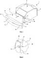
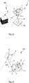
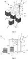
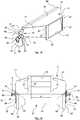
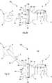
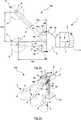
1 eine perspektivische Ansicht einer erfindungsgemäßen Verpackungsmaterialfertigungsmaschine gemäß einer beispielhaften Ausführung;2 eineDetailansicht II gemäß 1 3 eine Draufsicht auf einen Zuführtrichter derVerpackungsmaterialfertigungsmaschine aus 1 ;4 eine Schnittansicht gemäß der Linie IV-IV aus 3 ;5 eine Draufsicht auf dieVerpackungsmaterialfertigungsmaschine aus 1 ;6 eine Seitenansicht der Verpackungsmaterialfertigungsmaschine gemäß der1-5 und eines Verpackungsmaterialvorrats;7 eine Frontansicht zu 6 ;8 eine perspektivische Ansicht einer weiteren beispielhaften Ausführung einer erfindungsgemäßen Verpackungsmaterialfertigungsmaschine sowie eines Verpackungsmaterialvorrats;9 eine schematische Draufsicht zu8 ;10 eine perspektivische Ansicht einer weiteren beispielhaften Ausführung einer erfindungsgemäßen Verpackungsmaterialfertigungsmaschine und eines Verpackungsmaterialvorrats;11 eine Draufsicht zu10 ;12 eine perspektivische Ansicht einer weiteren beispielhaften Ausführung einer erfindungsgemäßen Verpackungsmaterialfertigungsmaschine mit einem Verpackungsmaterialvorrat bestehend aus vier Verpackungsmaterialvorratsstapeln;13 eine Seitenansicht zu12 ;14 eine Draufsicht zu den12 und 13 ;15 eine perspektivische Ansicht eines Ausschnitts einer weiteren beispielhaften Ausführung einer erfindungsgemäßen Verpackungsmaterialfertigungsmaschine;16 eine Draufsicht zu 15 ;17 eine Schnittansicht gemäß der Linie XVII- XVII gemäß16 ;18 eine perspektivische Rückansicht zu den15-17 ;19 eine Rückansicht zu den15-18 ; und20-25 verschiedene Ansichten zu beispielhaften Anordnungen aus erfindungsgemäßen Verpackungsmaterialfertigungsmaschinen und Verpackungsmaterialvorräten.
1 a perspective view of a packaging material production machine according to the invention according to an exemplary embodiment;2 a detailed view II according to1 3 a plan view of a feed hopper of the packagingmaterial manufacturing machine 1 ;4th a sectional view along the line IV-IV from3 ;5 Figure 3 is a plan view of the packagingmaterial manufacturing machine 1 ;6th a side view of the packaging material manufacturing machine according to FIG1-5 and a supply of packaging material;7th a front view too6th ;8th a perspective view of a further exemplary embodiment of a packaging material production machine according to the invention and a packaging material supply;9 a schematic plan view too8th ;10 a perspective view of a further exemplary embodiment of a packaging material manufacturing machine according to the invention and a packaging material supply;11 a top view too10 ;12th a perspective view of a further exemplary embodiment of a packaging material production machine according to the invention with a packaging material supply consisting of four packaging material supply stacks;13th a side view too12th ;14th a top view of the12th and13th ;15th a perspective view of a section of a further exemplary embodiment of a packaging material production machine according to the invention;16 a top view too15th ;17th a sectional view along the line XVII-XVII according to16 ;18th a perspective rear view of the15-17 ;19th a rear view to the15-18 ; and20-25 Various views of exemplary arrangements of packaging material production machines according to the invention and packaging material supplies.
In der folgenden Beschreibung beispielhafter Ausführungen der vorliegenden Erfindung ist eine erfindungsgemäße Verpackungsmaterialfertigungsmaschine im Allgemeinen mit der Bezugsziffer
In
Von der Verpackungsmaterialbearbeitungseinrichtung
Förderrichtungsabwärts umfasst der Zuführtrichter
Es ist somit möglich, Zuführtrichter
In
In
In der Draufsicht gemäß
In den
Die
Die Verpackungsmaterialfertigungsmaschine
Des Weiteren ist insbesondere aus
Der Verpackungsmaterialvorratsstapel
In den
In
In den
Die Anordnung
In der schematischen Seitenansicht gemäß
In Bezug auf die
Die Verpackungsmaterialfertigungsmaschine
Die lateralen, kegelstumpfförmigen Endabschnitte
Eine Verstelleinrichtung
Gemäß
In
In den
Die
Bei der Anordnung
Die
Die in der vorstehenden Beschreibung, den Figuren und den Ansprüchen offenbarten Merkmale können sowohl einzeln als auch in beliebiger Kombination für die Realisierung der Erfindung in den verschiedenen Ausgestaltungen von Bedeutung sein.The features disclosed in the above description, the figures and the claims can be important both individually and in any combination for the implementation of the invention in the various configurations.
BezugszeichenlisteList of reference symbols
- 11
- VerpackungsmaterialfertigungsmaschinePackaging material manufacturing machine
- 33
- ZuführtrichterFeed hopper
- 55
- VerpackungsmaterialvorratPackaging material supply
- 66th
- VerpackungsmaterialbahnrollePackaging material web roll
- 77th
- UmlenkstangeDeflection rod
- 88th
- RolleninnenseiteInside of the roll
- 99
- VerpackungsmaterialbearbeitungseinrichtungPackaging material processing device
- 1010
- UmlenkeinrichtungDeflection device
- 1111
- Gehäusecasing
- 1313th
- ZuführöffnungFeed opening
- 15, 17, 19, 2115, 17, 19, 21
- SchachtwandShaft wall
- 2323
- MontageplatteMounting plate
- 2525th
- BefestigungAttachment
- 2727
- NutGroove
- 2929
- StoßkanteAbutting edge
- 3131
- EingriffselementEngagement element
- 3333
- BiegestelleBending point
- 3535
- BetätigungsschalterActuation switch
- 3737
- VerpackungsmaterialbahnPackaging material web
- 3939
- VerpackungsmaterialvorratsstapeloberseitePackaging material supply stack top
- 4040
- Schlauchförmiger VerpackungsmaterialstrangTubular strand of packaging material
- 4141
- Oberes FaltblattUpper folder
- 43,45,47,4943,45,47,49
- FaltblattLeaflet
- 5151
- StänderStand
- 5353
- BodenauflageFloor support
- 5757
- UmlenkwelleDeflection shaft
- 59, 6159, 61
- Lateraler EndabschnittLateral end section
- 63, 6563, 65
- ZylinderabschnittCylinder section
- 67, 6967, 69
- StirnflächeFace
- 7171
- LagerungsöffnungStorage opening
- 7272
- LagerungsbolzenBearing bolt
- 7373
- WellenabschnittShaft section
- 7575
- VerstelleinrichtungAdjusting device
- 7777
- Platteplate
- 7979
- RastvertiefungLocking recess
- 8181
- BefestigungsbolzenFastening bolts
- 8383
- RastvorsprungLocking projection
- 8585
- VerbindungsteilConnecting part
- 8787
- LagerungsbolzenBearing bolt
- 89, 8889, 88
- EinführstangeInsertion rod
- 9191
- AbgabeöffnungDispensing opening
- 100100
- Anordnungarrangement
- 103103
- Abstanddistance
- 105, 107105, 107
- Winkelangle
- 113113
- VertikalhöheVertical height
- 111111
- UntergrundUnderground
- 109109
- HorizontalabstandHorizontal distance
- ll
- Krümmungsradius der UmlenkstangeRadius of curvature of the deflection rod
- cc
- Länge des ZuführtrichtersLength of the feed hopper
- dd
- Vertikalhöhe des ZuführtrichtersVertical height of the feed hopper
- ee
- Höhe der ZuführöffnungFeed opening height
- zz
- Gesamtlängserstreckung der UmlenkwelleTotal length of the deflection shaft
- yy
- Gesamtlängserstreckung der EndabschnitteTotal longitudinal extension of the end sections
- xx
- halber Öffnungswinkelhalf opening angle
- ww
- Gesamtlängserstreckung des WellenabschnittsTotal length of the shaft section
- αα
- Winkel der SchwenkbewegungAngle of pan movement
- maximaler Außendurchmesser der Endabschnittemaximum outside diameter of the end sections
- a, ba, b
- Durchmesser der EinführstangenDiameter of the insertion rods
- hH
- Winkel des SchachtsAngle of the shaft
- ff
- TrichterwinkelFunnel angle
- rr
- Höhe der AbgabeöffnungHeight of the dispensing opening
- ss
- Breite der AbgabeöffnungWidth of the dispensing opening
- FF.
- FörderrichtungConveying direction
- ZZ
- ZuförderrichtungFeed direction
- LL.
- BahnlängsrichtungLongitudinal direction of the web
- RR.
- RotationsachseAxis of rotation
- SS.
- SchwenkachseSwivel axis
ZITATE ENTHALTEN IN DER BESCHREIBUNGQUOTES INCLUDED IN THE DESCRIPTION
Diese Liste der vom Anmelder aufgeführten Dokumente wurde automatisiert erzeugt und ist ausschließlich zur besseren Information des Lesers aufgenommen. Die Liste ist nicht Bestandteil der deutschen Patent- bzw. Gebrauchsmusteranmeldung. Das DPMA übernimmt keinerlei Haftung für etwaige Fehler oder Auslassungen.This list of the documents listed by the applicant was generated automatically and is included solely for the better information of the reader. The list is not part of the German patent or utility model application. The DPMA assumes no liability for any errors or omissions.
Zitierte PatentliteraturPatent literature cited
- AU 2011/202898 B2 [0003]AU 2011/202898 B2 [0003]
Zitierte Nicht-PatentliteraturNon-patent literature cited
- Norm DIN EN ISO 1924-2 [0008, 0024, 0033]Standard DIN EN ISO 1924-2 [0008, 0024, 0033]
- DIN EN ISO 1924-3 [0008, 0024, 0033]DIN EN ISO 1924-3 [0008, 0024, 0033]
- Norm DIN EN ISO 2758 [0008, 0024, 0033]Standard DIN EN ISO 2758 [0008, 0024, 0033]
Claims (18)
Translated fromGermanPriority Applications (4)
| Application Number | Priority Date | Filing Date | Title |
|---|---|---|---|
| DE102019135629.6ADE102019135629A1 (en) | 2019-12-20 | 2019-12-20 | Packaging material production machine and deflection device |
| US17/786,793US20230138470A1 (en) | 2019-12-20 | 2020-12-10 | Packaging material production machine and diverter |
| PCT/EP2020/085534WO2021122312A1 (en) | 2019-12-20 | 2020-12-10 | Packaging material production machine and diverter |
| EP20829542.8AEP4076929A1 (en) | 2019-12-20 | 2020-12-10 | Packaging material production machine and diverter |
Applications Claiming Priority (1)
| Application Number | Priority Date | Filing Date | Title |
|---|---|---|---|
| DE102019135629.6ADE102019135629A1 (en) | 2019-12-20 | 2019-12-20 | Packaging material production machine and deflection device |
Publications (1)
| Publication Number | Publication Date |
|---|---|
| DE102019135629A1true DE102019135629A1 (en) | 2021-06-24 |
Family
ID=74068248
Family Applications (1)
| Application Number | Title | Priority Date | Filing Date |
|---|---|---|---|
| DE102019135629.6APendingDE102019135629A1 (en) | 2019-12-20 | 2019-12-20 | Packaging material production machine and deflection device |
Country Status (4)
| Country | Link |
|---|---|
| US (1) | US20230138470A1 (en) |
| EP (1) | EP4076929A1 (en) |
| DE (1) | DE102019135629A1 (en) |
| WO (1) | WO2021122312A1 (en) |
Cited By (2)
| Publication number | Priority date | Publication date | Assignee | Title |
|---|---|---|---|---|
| DE102023110434A1 (en) | 2023-04-24 | 2024-10-24 | Sprick Gmbh Bielefelder Papier- Und Wellpappenwerke & Co. | Packaging material manufacturing machine and system comprising a packaging material manufacturing machine and a packaging material supply |
| DE102023110436A1 (en) | 2023-04-24 | 2024-10-24 | Sprick Gmbh Bielefelder Papier- Und Wellpappenwerke & Co. | Packaging material manufacturing machine and system comprising a packaging material manufacturing machine and a packaging material supply |
Citations (8)
| Publication number | Priority date | Publication date | Assignee | Title |
|---|---|---|---|---|
| US2979829A (en)* | 1958-07-15 | 1961-04-18 | Nat Steel Corp | Roller and apparatus for transporting strip material |
| DE7618339U1 (en)* | 1975-07-10 | 1976-12-09 | Basf Ag, 6700 Ludwigshafen | SELF-CENTERING BELT GUIDE FOR BELT TRANSPORT |
| US20130296154A1 (en)* | 2011-06-16 | 2013-11-07 | Ranpak Corp. | Dunnage conversion machine and method with downstream feed monitor |
| US20160200065A1 (en)* | 2010-02-15 | 2016-07-14 | Ranpak Corp. | Void-fill dunnage conversion machine, stock material support, and method |
| WO2018005902A1 (en)* | 2016-06-30 | 2018-01-04 | Ranpak Corp. | Dunnage conversion machine and method and dunnage product |
| US20180099470A1 (en)* | 2010-12-23 | 2018-04-12 | Pregis Innovative Packaging Llc | Center-fed dunnage system feed and cutter |
| WO2018071384A1 (en)* | 2016-10-11 | 2018-04-19 | Sealed Air Corporation (Us) | Machine and method for producing void fill packaging material |
| DE102017109851A1 (en)* | 2017-05-08 | 2018-11-08 | Sprick Gmbh Bielefelder Papier- Und Wellpappenwerke & Co. | Device for manufacturing a cushioning product |
Family Cites Families (30)
| Publication number | Priority date | Publication date | Assignee | Title |
|---|---|---|---|---|
| US4839210A (en)* | 1985-10-28 | 1989-06-13 | Ranpak Corp. | Method and mechanism for producing cushioning dunnage product |
| US4750896A (en)* | 1985-10-28 | 1988-06-14 | Ranpak Corp. | Method and mechanism for producing cushioning dunnage product |
| US5211620A (en)* | 1991-11-01 | 1993-05-18 | Ranpak Corp. | Edge-tension controlling device for a cushioning conversion machine |
| US6190299B1 (en)* | 1995-03-24 | 2001-02-20 | Ranpak Corporation | Cushion producing machine |
| US5713825A (en)* | 1995-06-07 | 1998-02-03 | Ranpak Corp. | Cushioning conversion machine and method for converting stock material into a dunnage product having a casing and a stuffing within the casing |
| DE69604396T2 (en)* | 1995-06-07 | 2000-03-02 | Ranpak Corp., Concord Township | LOADING DEVICE AND METHOD FOR A MACHINE FOR PRODUCING UPHOLSTERY MATERIAL |
| EP0886573B1 (en)* | 1995-06-26 | 2003-02-19 | Ranpak Corp. | Cushioning conversion machine and its use |
| US5813967A (en)* | 1997-02-25 | 1998-09-29 | Ranpak Corp. | Cushioning conversion machine with guide roller, and method |
| EP0910505B1 (en)* | 1997-03-11 | 2004-09-22 | Ranpak Corp. | Cushioning conversion machine and method |
| DE19728371C1 (en)* | 1997-07-03 | 1999-01-14 | Lemo Maschb Gmbh | Device for cross-welding separation and stack-wise collecting and blocking of bags made of a plastic film web, in particular shirt-carrying bags |
| US6210310B1 (en)* | 1998-01-12 | 2001-04-03 | Ranpak Corp. | Cushioning conversion machine and method with enhanced stock separation and forming |
| ATE275035T1 (en)* | 1998-05-15 | 2004-09-15 | Ranpak Corp | MACHINE FOR PRODUCING UPHOLSTERY ELEMENTS |
| US6179765B1 (en)* | 1998-10-30 | 2001-01-30 | Ft Acquisition, L.P. | Paper dispensing system and method |
| CA2412440C (en)* | 2000-06-09 | 2010-08-10 | Ranpak Corp. | Dunnage conversion machine with translating grippers, and method and product |
| US20030073558A1 (en)* | 2001-10-15 | 2003-04-17 | Bill Chesterson | Machine and method for converting paper stock into dunnage |
| US6761505B2 (en)* | 2002-01-15 | 2004-07-13 | Torch Offshore, Inc. | Reel type pipeline laying ship and method |
| US6918489B2 (en)* | 2002-04-22 | 2005-07-19 | Ranpak Corp. | Dunnage converter system |
| EP2799223A3 (en)* | 2003-07-07 | 2014-12-31 | Ranpak Corp. | Cutterless dunnage converter and method |
| ATE445496T1 (en)* | 2004-08-20 | 2009-10-15 | Ranpak Corp | MACHINE AND METHOD FOR PRODUCING UPHOLSTERY ELEMENTS |
| US8167783B2 (en)* | 2006-04-11 | 2012-05-01 | Pack-Tiger Gmbh | Machine for the manufacture of paper padding |
| US7328541B2 (en)* | 2006-05-01 | 2008-02-12 | Sealed Air Corporation (Us) | Apparatus and method for controlling position of an edge of an advancing web of flexible material |
| WO2007143750A2 (en)* | 2006-06-10 | 2007-12-13 | Ranpak Corp. | Compact dunnage converter |
| US7744519B2 (en)* | 2006-09-14 | 2010-06-29 | Pregis Innovative Packaging, Inc. | System and method for crumpling paper substrates |
| EP2203304B1 (en)* | 2007-09-24 | 2015-05-13 | Ranpak Corp. | Dunnage conversion machine and method |
| US20090098996A1 (en)* | 2007-10-11 | 2009-04-16 | Sealed Air Corporation (Us) | Dunnaging Apparatus and Method with Controlled Web Tension |
| WO2012170474A1 (en)* | 2011-06-07 | 2012-12-13 | Ranpak Corp. | Reduced footprint dunnage conversion system and method |
| DE202012009025U1 (en)* | 2012-09-19 | 2012-12-19 | Sprick Gmbh Bielefelder Papier- Und Wellpappenwerke & Co. | Apparatus for manually generating a spiral packaging material |
| US20150119224A1 (en)* | 2013-10-24 | 2015-04-30 | Sealed Air Corporation (Us) | System For Producing Packaging Cushioning And Supply Structure Therefor |
| DE102017109829A1 (en)* | 2017-05-08 | 2018-11-08 | Sprick Gmbh Bielefelder Papier- Und Wellpappenwerke & Co. | Device for providing packaging material |
| US10828859B2 (en)* | 2017-11-20 | 2020-11-10 | Ecopack Group, Llc | Machine to produce twisted paper for loose fill packaging |
- 2019
- 2019-12-20DEDE102019135629.6Apatent/DE102019135629A1/enactivePending
- 2020
- 2020-12-10EPEP20829542.8Apatent/EP4076929A1/enactivePending
- 2020-12-10WOPCT/EP2020/085534patent/WO2021122312A1/ennot_activeCeased
- 2020-12-10USUS17/786,793patent/US20230138470A1/enactivePending
Patent Citations (8)
| Publication number | Priority date | Publication date | Assignee | Title |
|---|---|---|---|---|
| US2979829A (en)* | 1958-07-15 | 1961-04-18 | Nat Steel Corp | Roller and apparatus for transporting strip material |
| DE7618339U1 (en)* | 1975-07-10 | 1976-12-09 | Basf Ag, 6700 Ludwigshafen | SELF-CENTERING BELT GUIDE FOR BELT TRANSPORT |
| US20160200065A1 (en)* | 2010-02-15 | 2016-07-14 | Ranpak Corp. | Void-fill dunnage conversion machine, stock material support, and method |
| US20180099470A1 (en)* | 2010-12-23 | 2018-04-12 | Pregis Innovative Packaging Llc | Center-fed dunnage system feed and cutter |
| US20130296154A1 (en)* | 2011-06-16 | 2013-11-07 | Ranpak Corp. | Dunnage conversion machine and method with downstream feed monitor |
| WO2018005902A1 (en)* | 2016-06-30 | 2018-01-04 | Ranpak Corp. | Dunnage conversion machine and method and dunnage product |
| WO2018071384A1 (en)* | 2016-10-11 | 2018-04-19 | Sealed Air Corporation (Us) | Machine and method for producing void fill packaging material |
| DE102017109851A1 (en)* | 2017-05-08 | 2018-11-08 | Sprick Gmbh Bielefelder Papier- Und Wellpappenwerke & Co. | Device for manufacturing a cushioning product |
Cited By (4)
| Publication number | Priority date | Publication date | Assignee | Title |
|---|---|---|---|---|
| DE102023110434A1 (en) | 2023-04-24 | 2024-10-24 | Sprick Gmbh Bielefelder Papier- Und Wellpappenwerke & Co. | Packaging material manufacturing machine and system comprising a packaging material manufacturing machine and a packaging material supply |
| DE102023110436A1 (en) | 2023-04-24 | 2024-10-24 | Sprick Gmbh Bielefelder Papier- Und Wellpappenwerke & Co. | Packaging material manufacturing machine and system comprising a packaging material manufacturing machine and a packaging material supply |
| WO2024223682A1 (en) | 2023-04-24 | 2024-10-31 | Sprick Gmbh Bielefelder Papier- Und Wellpappenwerke & Co. | Packaging material production machine and system consisting of a packaging material production machine and a packaging material supply |
| WO2024223684A1 (en) | 2023-04-24 | 2024-10-31 | Sprick Gmbh Bielefelder Papier- Und Wellpappenwerke & Co. | Packaging material production machine and system consisting of a packaging material production machine and a packaging material supply |
Also Published As
| Publication number | Publication date |
|---|---|
| EP4076929A1 (en) | 2022-10-26 |
| US20230138470A1 (en) | 2023-05-04 |
| WO2021122312A1 (en) | 2021-06-24 |
Similar Documents
| Publication | Publication Date | Title |
|---|---|---|
| DE102019135629A1 (en) | Packaging material production machine and deflection device | |
| DE102017110517A1 (en) | Device for dispensing paper sections of predetermined length | |
| EP1209111A2 (en) | Device for depositing sheets | |
| DE4416522A1 (en) | Paper-web cutting device | |
| DE68914686T2 (en) | DEVICE FOR DEPOSITING COPY SHEETS. | |
| EP2837590A1 (en) | Sheet braking device, installation to provide sheets, and sheet braking apparatus | |
| EP0934223B1 (en) | Device for de-cambering a supporting material | |
| DE102021125092A1 (en) | Forming station with guide wall | |
| EP1976784B1 (en) | Apparatus for the stacked depositing of sheets | |
| DE3804903A1 (en) | DEVICE FOR FEEDING PAPER TO A QUICK PRINTER PROCESSING A SINGLE SHEET | |
| DE2432738C3 (en) | Device for aligning two-dimensional pieces lying on top of one another | |
| EP3359478B1 (en) | Folding belt for a device for folding folding-box blanks | |
| EP1454864B1 (en) | Method and apparatus for transporting a substantially sheet-like element, in particular in a printing machine | |
| DE102021125103A1 (en) | Forming station with drive | |
| EP1358119A1 (en) | Deposit device for a stack of sheets | |
| DE102005027712A1 (en) | Device for processing sheet-shaped value documents | |
| EP1237805B1 (en) | Device for deviating an overlapping stream on a roller table | |
| EP0322398A1 (en) | Folding device | |
| EP3549890B1 (en) | Etiquette dispensing device and corresponding printer | |
| DE10206323A1 (en) | Support device for a material web | |
| DE102023110436A1 (en) | Packaging material manufacturing machine and system comprising a packaging material manufacturing machine and a packaging material supply | |
| DE102021125142A1 (en) | Forming station with adjustable boundary wall and/or with folding cheeks | |
| EP4408654A2 (en) | Apparatus for mechanically producing a three-dimensional packaging article from a sheet-like starting material and packaging article | |
| DE1913638C (en) | Cutting device | |
| DE102019119675A1 (en) | Device for transferring linerless labels |
Legal Events
| Date | Code | Title | Description |
|---|---|---|---|
| R012 | Request for examination validly filed | ||
| R082 | Change of representative | Representative=s name:SKM-IP SCHMID KRAUSS KUTTENKEULER MALESCHA SCH, DE |