Movatterモバイル変換


[0]ホーム

URL:


DE102019135128A1 - Plug-in contact device to avoid an electric arc when disconnecting a direct current connection - Google Patents

Plug-in contact device to avoid an electric arc when disconnecting a direct current connection
Download PDF

Info

Publication number
DE102019135128A1
DE102019135128A1DE102019135128.6ADE102019135128ADE102019135128A1DE 102019135128 A1DE102019135128 A1DE 102019135128A1DE 102019135128 ADE102019135128 ADE 102019135128ADE 102019135128 A1DE102019135128 A1DE 102019135128A1
Authority
DE
Germany
Prior art keywords
contact
connection
connector
switching unit
state
Prior art date
Legal status (The legal status is an assumption and is not a legal conclusion. Google has not performed a legal analysis and makes no representation as to the accuracy of the status listed.)
Withdrawn
Application number
DE102019135128.6A
Other languages
German (de)
Inventor
Marc Klimpel
Fredrik Brand
Karsten Krome
Rüdiger Meyer
Rainer Durth
Markus Hanses
Martin Schäfers
Ralf Beckmann
Sebastian Loke
Philipp Jürgensmeier
Current Assignee (The listed assignees may be inaccurate. Google has not performed a legal analysis and makes no representation or warranty as to the accuracy of the list.)
Phoenix Contact GmbH and Co KG
Original Assignee
Phoenix Contact GmbH and Co KG
Priority date (The priority date is an assumption and is not a legal conclusion. Google has not performed a legal analysis and makes no representation as to the accuracy of the date listed.)
Filing date
Publication date
Application filed by Phoenix Contact GmbH and Co KGfiledCriticalPhoenix Contact GmbH and Co KG
Priority to DE102019135128.6ApriorityCriticalpatent/DE102019135128A1/en
Priority to JP2022537690Aprioritypatent/JP7398564B2/en
Priority to US17/785,454prioritypatent/US20230178925A1/en
Priority to EP20833789.9Aprioritypatent/EP4078737B1/en
Priority to CN202080088329.1Aprioritypatent/CN114830461B/en
Priority to PCT/EP2020/086513prioritypatent/WO2021122811A1/en
Publication of DE102019135128A1publicationCriticalpatent/DE102019135128A1/en
Withdrawnlegal-statusCriticalCurrent

Links

Images

Classifications

Landscapes

Abstract

Translated fromGerman

Eine Steckkontaktvorrichtung (100) zur Löschung eines Lichtbogens umfasst einen Hauptkontakt, HA (112), und einen Hilfskontakt, HI (114), die jeweils eine erste Kontakthälfte, HA1 (112-1) bzw. HI1 (114-1), und eine zweite Kontakthälfte, HA2 (112-2) bzw. HI1 (114-2) umfassen, die lösbar zusammensteckbar sind. Der HA (112) verbindet in einem zusammengesteckten Zustand T0die HA1 (112-1) und HA2 (112-2), während der HI (114) in T0die Hl1 (114-1) und die HI2 (114-2) trennt. In einem gelösten Zustand T3sind sowohl die HA1 (112-1) und die HA2 (112-2) als auch die Hl1 (114-1) und die HI2 (114-2) getrennt. In einem ersten Zwischenzustand T1zwischen T0und T3sind sowohl die HA1 (112-1) und die HA2 (112-2) als auch die Hl1 (114-1) und die HI2 (114-2) verbunden. In einem zweiten Zwischenzustand T2zwischen T1und T3sind die HA1 (112-1) und die HA2 (112-2) getrennt, während die HA2 (112-2) und die HI2 (114-2) verbunden sind. Eine elektronische Schalteinheit (120) verbindet in Reaktion auf einen Übergang von T0zu T1HA1 (112-1) mit HI1 (114-1). In Reaktion auf einen Übergang von T1zu T2und/oder von T2zu T3werden diese getrennt.A plug contact device (100) for extinguishing an arc comprises a main contact, HA (112), and an auxiliary contact, HI (114), each of which has a first contact half, HA1 (112-1) or HI1 (114-1), and a second contact half, HA2 (112-2) and HI1 (114-2), which can be detachably plugged together. The HA (112) connects the HA1 (112-1) and HA2 (112-2) in a mated state T0, while the HI (114) in T0 separates the HI1 (114-1) and the HI2 (114-2). In a released state T3, both the HA1 (112-1) and the HA2 (112-2) and the Hl1 (114-1) and the HI2 (114-2) are separated. In a first intermediate state T1 between T0 and T3, both the HA1 (112-1) and the HA2 (112-2) as well as the Hl1 (114-1) and the HI2 (114-2) are connected. In a second intermediate state T2 between T1 and T3, the HA1 (112-1) and the HA2 (112-2) are separated, while the HA2 (112-2) and the HI2 (114-2) are connected. An electronic switching unit (120) connects HA1 (112-1) to HI1 (114-1) in response to a transition from T0 to T1. In response to a transition from T1 to T2 and / or from T2 to T3, these are disconnected.

Description

Translated fromGerman

Die Erfindung betrifft eine Steckkontaktvorrichtung zur Vermeidung oder Löschung eines Lichtbogens beim Trennen oder Schließen einer Gleichstromverbindung.The invention relates to a plug contact device for avoiding or extinguishing an arc when a direct current connection is disconnected or closed.

Beim Trennen oder Schließen einer Gleichstrom-Verbindung (DC-Verbindung) muss, anders als bei einer Wechselstrom-Anwendung (AC-Anwendung), vermehrt mit einem Lichtbogen gerechnet werden. Besonders bei Steckverbindern stellt dies eine Herausforderung dar. Zum einen führt der Lichtbogen zu Schäden am Steckverbinder, sowohl an Gehäuseteilen als auch an den Kontakten. Zum anderen birgt der Lichtbogen aber auch eine Gefahr für den Bediener.When disconnecting or closing a direct current connection (DC connection), in contrast to an alternating current application (AC application), an electric arc must be expected more often. This is a challenge, especially with connectors. On the one hand, the arc leads to damage to the connector, both to housing parts and to the contacts. On the other hand, the arc also harbors a danger for the operator.

Es gibt verschiedene Konzepte, den Lichtbogen mit mechanischen Hilfsmitteln zu löschen, wie beispielsweise Opferzonen, oder mittels eines sogenannten Blasmagneten (aufgrund der auf das Plasma des Lichtbogens wirkenden Lorentz-Kraft) oder aufgrund einer Geschwindigkeit der Kontakttrennung.There are various concepts for extinguishing the arc with mechanical aids, such as sacrificial zones, or by means of a so-called blow magnet (due to the Lorentz force acting on the plasma of the arc) or due to a speed of contact separation.

Eine weitere Alternative ist die elektronische Funkenlöschung. Dabei wird der Lichtbogen mithilfe elektronischer Komponenten unterdrückt. Das Prinzip lässt sich mit einem elektronischen Schalter vergleichen. Wie bei einem mechanischen Schalter wird der Stromkreis unterbrochen. Da jedoch kein physischer Kontakt geöffnet wird, entsteht dabei auch kein Lichtbogen. Der Stromkreis wird mittels elektronischer Komponenten unterbrochen. Halbleiterbauelemente wie Bipolartransistoren mit isolierter Gate-Elektrode (IGBTs), Metall-Oxid-Halbleiter-Feldeffekttransistoren (MOSFETs) oder auch Varistoren verlagern dabei die Schaltleistung auf die elektronischen Baugruppen und die Kontakte werden somit geschützt. Solche Technologien sind beispielsweise in den DruckschriftenEP 2 742 565 B1,US 2018/0006447 A1,DE000010253749A1 undDE10 2007 043 512 A1 beschrieben.Another alternative is electronic spark extinguishing. The arc is suppressed with the help of electronic components. The principle can be compared to an electronic switch. As with a mechanical switch, the circuit is broken. However, since no physical contact is opened, no arcing occurs. The circuit is interrupted by electronic components. Semiconductor components such as bipolar transistors with insulated gate electrodes (IGBTs), metal-oxide-semiconductor field-effect transistors (MOSFETs) or varistors shift the switching power to the electronic assemblies and the contacts are thus protected. Such technologies are for example in thepublications EP 2 742 565 B1 , US 2018/0006447 A1 , DE000010253749A1 and DE10 2007 043 512 A1 described.

Dabei fließt der Strom im Normalbetrieb entweder permanent über die Elektronik, was kontinuierlich Verlustleistung erzeugt, oder während des Schaltvorganges wird der Stromfluss kurzzeitig über die Elektronik geführt und abgeschaltet, was energietechnisch deutlich besser ist. In diesem Fall ist ein zusätzlicher Hilfskontakt erforderlich, der parallel zu einem der Lastkontakte liegt und den Stromfluss über die Elektronik ermöglicht. Diese Varianten, wie beispielsweise in den DruckschriftenEP 2 742 565 B1 undUS 2018/0006447 A1 beschrieben, können sowohl in ein Steckverbindergehäuse integriert werden, als auch in einer Steckerleiste oder in einem Schaltschrank untergebracht werden. Die zuletzt beschriebene zentrale Platzierung der Elektronik in einer Steckerleiste oder in einem Schaltschrank hat dabei den Vorteil, dass mit einem Modul beliebig viele Steckverbinder betrieben werden können. Wie beispielsweise im DokumentEP 2 742 565 B1 beschrieben, müssen dann in den Zuleitungen zu jedem der Hilfskontakte entsprechende Dioden verbaut werden, damit kein Kurzschluss zwischen den verschiedenen Strängen mehrerer Steckverbinder entsteht und nur der Strom des derzeit schaltenden Stranges (bzw. zu trennenden oder zu verbindenden Steckverbinders) über die Elektronik fließt.In normal operation, the current either flows permanently through the electronics, which continuously generates power loss, or during the switching process, the current flow is briefly passed through the electronics and switched off, which is significantly better in terms of energy. In this case, an additional auxiliary contact is required, which is parallel to one of the load contacts and enables the current to flow through the electronics. These variants, as for example in thepublications EP 2 742 565 B1 and US 2018/0006447 A1 described, can be integrated in a connector housing, as well as in a connector strip or in a control cabinet. The central placement of the electronics in a connector strip or in a control cabinet described last has the advantage that any number of connectors can be operated with one module. As in the document, forexample EP 2 742 565 B1 In this case, appropriate diodes must be installed in the supply lines to each of the auxiliary contacts so that no short-circuit occurs between the various strings of several connectors and only the current of the string currently switched (or the connector to be disconnected or connected) flows through the electronics.

Durch die im DokumentEP 2 742 565 B1 beschriebenen Dioden können zwar mehrere Steckverbinder parallel mit einem einzigen Elektronikmodul versorgt werden, allerdings funktioniert das nur für unidirektionale Netze. Eine Besonderheit von DC-Netzen ist, dass Energieflüsse bidirektional sein können, wie beispielsweise bei Akkumulatoren (Sekundärzellen), die sowohl Quelle, als auch Verbraucher des Gleichstroms sein können. Ebenso können Elektromaschinen als Verbraucher des Gleichstroms arbeiten, aber auch generatorisch beim Bremsen Energie zurückspeisen. Bei einer bidirektionalen Anwendung, beispielsweise dem Wechsel zwischen motorischem und generatorischem Betrieb einer Elektromaschine, funktioniert die beschriebene Diodenschaltung nicht. Hier müsste mit einem deutlichen Mehraufwand eine aufwändigere Schaltung jedes einzelnen Hilfskontakts umgesetzt werden.Through the in thedocument EP 2 742 565 B1 Although several connectors can be supplied in parallel with a single electronic module, this only works for unidirectional networks. A special feature of DC networks is that energy flows can be bidirectional, as is the case with accumulators (secondary cells), which can be both a source and a consumer of direct current. Electric machines can also work as consumers of direct current, but can also feed back energy as a generator when braking. In the case of a bidirectional application, for example the change between motor and generator operation of an electric machine, the diode circuit described does not work. Here, a more complex switching of each individual auxiliary contact would have to be implemented with a significant additional effort.

Somit besteht die Aufgabe, eine Steckkontaktvorrichtung zur Vermeidung oder Löschung eines Lichtbogens beim Trennen oder Schließen einer Gleichstromverbindung bereitzustellen, welche sowohl in einem unidirektionalem als auch in einem bidirektionalen Netz betrieben werden kann.The object is therefore to provide a plug contact device for avoiding or extinguishing an arc when a direct current connection is disconnected or closed, which can be operated both in a unidirectional and in a bidirectional network.

Die Aufgabe wird mit den Merkmalen des unabhängigen Anspruchs gelöst. Zweckmäßige Ausgestaltungen und vorteilhafte Weiterbildungen der Erfindung sind in den abhängigen Ansprüchen angegeben.The object is achieved with the features of the independent claim. Appropriate configurations and advantageous developments of the invention are specified in the dependent claims.

Ausführungsbeispiele der Erfindung sind im Folgenden unter teilweiser Bezugnahme auf die Figuren beschrieben.Embodiments of the invention are described below with partial reference to the figures.

Gemäß einem Aspekt ist eine Steckkontaktvorrichtung zur Vermeidung oder Löschung eines Lichtbogens beim Trennen oder Schließen einer Gleichstromverbindung bereitgestellt. Die Steckkontaktvorrichtung umfasst mindestens einen Steckverbinder mit jeweils einem Hauptkontakt (HA) und einem Hilfskontakt (HI). Der HA umfasst eine erste Kontakthälfte (HA1) und eine zweite Kontakthälfte (HA2), die lösbar zusammensteckbar sind. Der HA ist dazu ausgebildet, in einem zusammengesteckten Zustand (To) des jeweiligen Steckverbinders die HA1 und die HA2 elektrisch leitend zu verbinden. Ferner ist der HA dazu ausgebildet, in einem gelösten Zustand (T3) des jeweiligen Steckverbinders die HA1 und die HA2 galvanisch zu trennen. Weiterhin ist der HA dazu ausgebildet, in einem ersten Zwischenzustand (T1) des jeweiligen Steckverbinders zwischen dem zusammengesteckten Zustand (To) und dem gelösten Zustand (T3) die HA1 und die HA2 elektrisch leitend zu verbinden und in einem zweiten Zwischenzustand (T2) des jeweiligen Steckverbinders zwischen dem ersten Zwischenzustand (T1) und dem gelösten Zustand (T3) die HA1 und die HA2 galvanisch zu trennen. Der Hilfskontakt (HI) umfasst eine erste Kontakthälfte (HI1) und eine zweite Kontakthälfte (HI2), die lösbar zusammensteckbar sind. Der HI ist dazu ausgebildet, im zusammengesteckten Zustand (T0) des jeweiligen Steckverbinders die HI1 und die HI2 galvanisch zu trennen. Ferner ist der HI dazu ausgebildet, im gelösten Zustand (T3) des jeweiligen Steckverbinders die HI1 und die HI2 galvanisch zu trennen. Weiterhin ist der HI dazu ausgebildet, im ersten Zwischenzustand (T1) des jeweiligen Steckverbinders die HI1 und die HI2 elektrisch leitend zu verbinden und im zweiten Zwischenzustand (T2) des jeweiligen Steckverbinders die HI1 und die HI2 elektrisch leitend zu verbinden. Die HA2 und die HI2 sind (vorzugsweise in jedem der 4 Zustände) elektrisch leitend verbunden. Die Steckkontaktvorrichtung umfasst ferner eine elektronische Schalteinheit, deren erster Anschluss mit der HA1 und deren zweiter Anschluss mit der HI1 (vorzugsweise in jedem der 4 Zustände) elektrisch leitend verbunden sind. Die elektronische Schalteinheit ist dazu ausgebildet, in Reaktion auf einen Übergang vom zusammengesteckten Zustand (To) in den ersten Zwischenzustand (T1) den ersten Anschluss und den zweiten Anschluss elektrisch leitend zu verbinden oder eine Impedanz zwischen dem ersten Anschluss und dem zweiten Anschluss zu verkleinern, und in Reaktion auf einen Übergang vom ersten Zwischenzustand (T1) in den zweiten Zwischenzustand (T2) und/oder vom zweiten Zwischenzustand (T2) in den gelösten Zustand (T3) den ersten Anschluss und den zweiten Anschluss elektrisch zu trennen oder eine Impedanz zwischen dem ersten Anschluss und dem zweiten Anschluss zu vergrößern.According to one aspect, a plug contact device is provided for avoiding or extinguishing an arc when separating or closing a direct current connection. The plug contact device comprises at least one plug connector, each with a main contact (HA) and an auxiliary contact (HI). The HA comprises a first contact half (HA1) and a second contact half (HA2) which can be detachably plugged together. The HA is designed to connect the HA1 and the HA2 in an electrically conductive manner when the respective connector is plugged together (To). Furthermore, the HA is designed to be in a released state State (T3 ) of the respective connector to galvanically separate the HA1 and the HA2. Furthermore, the HA is designed to, in a first intermediate state ( T1 ) of the respective connector between the plugged-together state (To) and the disconnected state (T3 ) to connect the HA1 and the HA2 in an electrically conductive manner and in a second intermediate state ( T2 ) of the respective connector between the first intermediate state ( T1 ) and the released state (T3 ) to galvanically separate the HA1 and the HA2. The auxiliary contact (HI) comprises a first contact half (HI1) and a second contact half (HI2), which can be detachably plugged together. The HI is designed to operate when plugged together ( T0 ) of the respective connector to galvanically separate the HI1 and the HI2. Furthermore, the HI is designed to galvanically separate the HI1 and the HI2in the released state (T 3) of the respective connector. Furthermore, the HI is designed to, in the first intermediate state ( T1 ) of the respective connector to connect the HI1 and the HI2 in an electrically conductive manner and in the second intermediate state ( T2 ) of the respective connector to connect the HI1 and the HI2 in an electrically conductive manner. The HA2 and the HI2 are electrically connected (preferably in each of the 4 states). The plug contact device also comprises an electronic switching unit, the first connection of which is connected to the HA1 and the second connection of which is electrically conductively connected to the HI1 (preferably in each of the 4 states). The electronic switching unit is designed to respond to a transition from the assembled state (To) to the first intermediate state ( T1 ) to connect the first connection and the second connection in an electrically conductive manner or to reduce an impedance between the first connection and the second connection, and in response to a transition from the first intermediate state ( T1 ) to the second intermediate state ( T2 ) and / or from the second intermediate state ( T2 ) in the released state (T3 ) to electrically separate the first connection and the second connection or to increase an impedance between the first connection and the second connection.

In einem Ausführungsbeispiel der Steckkontaktvorrichtung kann der HA im zusammengesteckten Zustand die HA1 und die HA2 elektrisch leitend verbinden, während der HI im zusammengesteckten Zustand die HI1 und die HI2 galvanisch trennen kann. Im gelösten Zustand können sowohl die HA1 und die HA2 als auch die HI1 und die HI2 jeweils galvanisch getrennt sein. Im ersten Zwischenzustand zwischenT0 und T3 können sowohl die HA1 und die HA2 als auch die HI1 und die HI2 jeweils elektrisch leitend verbunden sein. Im zweiten Zwischenzustand zwischenT1 und T3 können die HA1 und die HA2 galvanisch getrennt sein, während die HA2 und die HI2 elektrisch leitend verbunden sein können.In one embodiment of the plug contact device, the HA can connect the HA1 and the HA2 in an electrically conductive manner in the plugged-together state, while the HI can galvanically separate the HI1 and the HI2 in the plugged-together state. In the released state, both the HA1 and the HA2 as well as the HI1 and the HI2 can each be galvanically separated. In the first intermediate state between T0 and T3 , both the HA1 and the HA2 and also the HI1 and the HI2 can each be connected in an electrically conductive manner. In the second intermediate state between T1 and T3 , the HA1 and the HA2 can be galvanically separated, while the HA2 and the HI2 can be connected in an electrically conductive manner.

Ausführungsbeispiele können eine Steckkontaktvorrichtung ermöglichen, die auf Dioden an Hilfskontakten verzichtet. Um auf die Diode verzichten zu können, ist vorgesehen, dass die Kontakthälften (HI1 und HI2) des Hilfskontakts (HI) im zusammengesteckten Zustand galvanisch getrennt sind, beispielsweise mittels eines teilweise isolierten Stiftkontakt als HI1 oder HI2.Embodiments can enable a plug contact device that dispenses with diodes on auxiliary contacts. In order to be able to do without the diode, it is provided that the contact halves (HI1 and HI2) of the auxiliary contact (HI) are galvanically separated when plugged together, for example by means of a partially isolated pin contact as HI1 or HI2.

Beispielsweise ist der HI so gestaltet, dass im zusammengesteckten Zustand (beispielsweise einem komplett gesteckten Zustand) keine leitende Verbindung zwischen HI1 und HI2 (beispielsweise Stiftkontakt und Buchsenkontakt) besteht. Erst beim Trennen der Gleichstromverbindung (d.h., einem Übergang in Richtung des gelösten Zustands) wird der Stromkreis über die elektronische Schalteinheit (kurz: Elektronik) geschlossen, vorzugsweise beim Übergang in den ersten Zwischenzustand. Dies geschieht vorzugsweise, bevor an dem voreilenden Hauptkontakt (HA, auch: Lastkontakt) der Lichtbogen entsteht bzw. entstehen würde ohne HI, beispielsweise beim Übergang in den zweiten Zwischenzustand. Der Lichtbogen löst dann die elektronischen Schalteinheit (kurz: Elektronik) aus, beispielsweise aufgrund eines Spannungsabfalls zwischen dem ersten und zweiten Anschluss, woraufhin der Strom über den Hilfskontakt (HI) und die Elektronik geleitet wird. Die Elektronik unterbricht dann direkt (beispielsweise nach einer Zeitspanne, die kürzer ist als eine typische Zeitspanne des Übergangs vom zweiten Zwischenzustand zum gelösten Zustand) den Stromkreis und ermöglicht so ein lastfreies Trennen der elektrischen Verbindung (und/oder lastfreies Öffnen des HI) ohne Lichtbogen. Eine beispielhafte Wirkungsweise der Elektronik ist in der DruckschriftEP 2 742 565 B 1 beschrieben.For example, the HI is designed in such a way that there is no conductive connection between HI1 and HI2 (for example pin contact and socket contact) when it is plugged together (for example completely plugged in). Only when the direct current connection is disconnected (ie, a transition in the direction of the released state) is the circuit closed via the electronic switching unit (electronics for short), preferably during the transition to the first intermediate state. This is preferably done before the arc arises or would arise without HI at the leading main contact (HA, also: load contact), for example during the transition to the second intermediate state. The arc then triggers the electronic switching unit (electronics for short), for example due to a voltage drop between the first and second connection, whereupon the current is conducted via the auxiliary contact (HI) and the electronics. The electronics then interrupt the circuit directly (for example after a period of time that is shorter than a typical period of time for the transition from the second intermediate state to the released state) and thus enables the electrical connection to be disconnected (and / or to open the HI without any load) without an arc. An exemplary mode of operation of the electronics is in thepublication EP 2 742 565B 1 described.

Bei einer Steckkontaktvorrichtung mit mehreren Steckverbindern, die auch als Stränge bezeichnet werden, können Ausführungsbeispiele der Steckkontaktvorrichtung die Trennung der einzelnen Stränge voneinander durch die elektrische (vorzugsweise physikalische oder galvanische) Trennung der jeweiligen Hilfskontakte (HI) der Steckkontaktvorrichtung im zusammengesteckten Zustand bewerkstelligen.In the case of a plug contact device with several plug connectors, which are also referred to as strands, embodiments of the plug contact device can accomplish the separation of the individual strands from one another by the electrical (preferably physical or galvanic) separation of the respective auxiliary contacts (HI) of the plug contact device when plugged together.

Hierin kann ein Zustand galvanischer Trennung auch als offener Zustand bezeichnet sein. Ein Zustand elektrisch leitender Verbindung kann auch als geschlossener Zustand bezeichnet sein.A state of galvanic isolation can also be referred to here as an open state. A state of electrically conductive connection can also be referred to as a closed state.

Der mindestens eine Steckverbinder kann zusätzlich zu dem Hauptkontakt (HA) und dem Hilfskontakt (HI), der auch als Steuerkontakt bezeichnet werden kann, einen Gegenpolkontakt (GE), der auch als zweiter Hauptkontakt bezeichnet werden kann, und/oder einen Erdungskontakt (PE, „physical earth“) umfassen. Der GE und/oder der PE können jeweils eine erste Kontakthälfte und eine zweite Kontakthälfte umfassen.In addition to the main contact (HA) and the auxiliary contact (HI), which can also be referred to as control contact, the at least one connector can have an opposite pole contact (GE), which can also be referred to as the second main contact, and / or a grounding contact (PE, "Physical earth"). The GE and / or the PE can each comprise a first contact half and a second contact half.

Der Hauptkontakt (HA) kann mit dem Pluspol einer Gleichstromquelle verbunden oder verbindbar sein. Der Gegenpolkontakt (GE) kann mit dem Minuspol einer Gleichstromquelle verbunden oder verbindbar sein. Der GE und/oder der PE können im zusammengesteckten Zustand (T0), im ersten Zwischenzustand (T1) und im zweiten Zwischenzustand (T2) elektrisch leitend verbunden und im gelösten Zustand (T3) galvanisch getrennt sein.The main contact (HA) can be connected or connectable to the positive pole of a direct current source. The opposite pole contact (GE) can be connected or connectable to the negative pole of a direct current source. The GE and / or the PE can be plugged together ( T0 ), in the first intermediate state ( T1 ) and in the second intermediate state ( T2 ) be electrically connected and galvanically separated in the released state (T3).

Die elektronische Schalteinheit kann mindestens einen Halbleiterschalter umfassen. Die elektronische Schalteinheit kann mit dem HI des mindestens einen Steckverbinders in Reihe geschaltet sein. Der HI kann mittels der elektronischen Schalteinheit wahlweise parallel zu dem HA geschaltet werden. Die elektronische Schalteinheit kann auch als Löschelektronik bezeichnet werden.The electronic switching unit can comprise at least one semiconductor switch. The electronic switching unit can be connected in series with the HI of the at least one connector. The HI can optionally be switched in parallel to the HA by means of the electronic switching unit. The electronic switching unit can also be referred to as extinguishing electronics.

Die elektronische Schalteinheit kann ferner dazu ausgebildet sein, in Reaktion auf einen Übergang vom gelösten Zustand (T3) in den zweiten Zwischenzustand (T2) und/oder vom zweiten Zwischenzustand (T2) in den ersten Zwischenzustand (T1) den ersten Anschluss und den zweiten Anschluss elektrisch leitend zu verbinden oder eine Impedanz zwischen dem ersten Anschluss und dem zweiten Anschluss zu verkleinern, und in Reaktion auf einen Übergang vom ersten Zwischenzustand (T1) in den zusammengesteckten Zustand (To) den ersten Anschluss und den zweiten Anschlusselektrisch zu trennen oder eine Impedanz zwischen dem ersten Anschluss und dem zweiten Anschluss zu vergrößern.The electronic switching unit can also be designed to respond to a transition from the released state (T3 ) to the second intermediate state ( T2 ) and / or from the second intermediate state ( T2 ) to the first intermediate state ( T1 ) to connect the first connection and the second connection in an electrically conductive manner or to reduce an impedance between the first connection and the second connection, and in response to a transition from the first intermediate state ( T1 ) to electrically separate the first connection and the second connection in the mated state (To) or to increase an impedance between the first connection and the second connection.

Die elektronische Schalteinheit kann dazu ausgebildet sein, den ersten Anschluss und den zweiten Anschluss für einen bidirektionalen Stromfluss oder für beide Stromrichtungen elektrisch leitend zu verbinden. Ein bidirektionaler Stromfluss kann durch einen Gleichrichter gewährleistet werden.The electronic switching unit can be designed to connect the first connection and the second connection for a bidirectional current flow or for both current directions in an electrically conductive manner. A bidirectional current flow can be guaranteed by a rectifier.

Der mindestens eine Steckverbinder kann jeweils eine erste Steckverbinderhälfte und eine zweite Steckverbinderhälfte umfassen. Die erste Steckverbinderhälfte kann die HA1 und die HI1 umfassen. Die erste Steckverbinderhälfte kann ferner eine erste Kontakthälfte GE1 des GE und optional eine erste Kontakthälfte PE1 des PE umfassen. Die zweite Steckverbinderhälfte kann die HA2 und die HI2 umfassen. Die zweite Steckverbinderhälfte kann ferner eine zweite Kontakthälfte GE2 des GE und optional eine zweite Kontakthälfte PE2 des PE umfassen. Die erste Steckverbinderhälfte kann auch als Steckdose bezeichnet werden. Die zweite Steckverbinderhälfte kann auch als Netzstecker bezeichnet werden.The at least one connector can each comprise a first connector half and a second connector half. The first connector half can comprise the HA1 and the HI1. The first connector half can furthermore comprise a first contact half GE1 of the GE and optionally a first contact half PE1 of the PE. The second connector half can comprise the HA2 and the HI2. The second connector half can furthermore comprise a second contact half GE2 of the GE and optionally a second contact half PE2 of the PE. The first half of the connector can also be referred to as a socket. The second half of the connector can also be referred to as a power plug.

Die erste Steckverbinderhälfte und die zweite Steckverbinderhälfte des jeweiligen Steckverbinders können im zusammengesteckten Zustand mechanisch verbunden sein. Die erste Steckverbinderhälfte und die zweite Steckverbinderhälfte des jeweiligen Steckverbinders können im gelösten Zustand räumlich getrennt sein.The first connector half and the second connector half of the respective connector can be mechanically connected in the mated state. The first connector half and the second connector half of the respective connector can be spatially separated in the released state.

Jede Steckverbinderhälfte kann ein Gehäuse umfassen.Each connector half can include a housing.

Ein Pol einer Gleichstromquelle der Gleichstromverbindung, vorzugsweise ein Pluspol der Gleichstromquelle, kann mit der HA1 des Hauptkontakts und/oder dem ersten Anschluss der elektronischen Schalteinheit elektrisch leitend verbunden oder verbindbar sein, wobei ein Pol eines elektrischen Verbrauchers, vorzugsweise ein Pluspol des Verbrauchers, mit der HA2 des Hauptkontakts und/oder der HI2 des Hilfskontakts elektrisch leitend verbunden oder verbindbar ist. Alternativ oder ergänzend kann ein Pol einer Gleichstromquelle der Gleichstromverbindung, vorzugsweise ein Pluspol der Gleichstromquelle, mit der HA2 des Hauptkontakts und/oder der HI2 des Hilfskontakts elektrisch leitend verbunden oder verbindbar sein, wobei ein Pol eines elektrischen Verbrauchers, vorzugsweise ein Pluspol des Verbrauchers, mit der HA1 des Hauptkontakts und/oder dem ersten Anschluss der elektronischen Schalteinheit elektrisch leitend verbunden oder verbindbar ist.A pole of a direct current source of the direct current connection, preferably a positive pole of the direct current source, can be electrically conductively connected or connectable to the HA1 of the main contact and / or the first connection of the electronic switching unit, with one pole of an electrical consumer, preferably a positive pole of the consumer, being connected to the HA2 of the main contact and / or the HI2 of the auxiliary contact is electrically connected or connectable. Alternatively or in addition, a pole of a direct current source of the direct current connection, preferably a positive pole of the direct current source, can be electrically conductively connected or connectable to the HA2 of the main contact and / or the HI2 of the auxiliary contact, with a pole of an electrical consumer, preferably a positive pole of the consumer the HA1 of the main contact and / or the first connection of the electronic switching unit is electrically connected or connectable.

Beispielsweise kann die Gleichstromquelle einen wiederaufladbaren elektrischen Energiespeicher (vorzugsweise Sekundärzellen) umfassen und der elektrische Verbraucher kann eine Elektromaschine (E-Maschine) umfassen. Die E-Maschine kann (vorzugsweise temporär) generatorisch betrieben werden, wobei sich die Stromrichtung des Gleichstroms (vorzugsweise zu einer Rekuperation) durch die Steckkontaktvorrichtung umkehrt.For example, the direct current source can comprise a rechargeable electrical energy store (preferably secondary cells) and the electrical consumer can comprise an electric machine (e-machine). The electric machine can be operated as a generator (preferably temporarily), with the current direction of the direct current reversing (preferably for recuperation) through the plug contact device.

Die HA1 kann einen Stiftkontakt und die HA2 einen Buchsenkontakt umfassen. Alternativ kann die HA2 einen Stiftkontakt und die HA1 einen Buchsenkontakt umfassen. Alternativ oder ergänzend kann die HI1 einen Stiftkontakt und die HI2 einen Buchsenkontakt umfassen. In einer weiteren Alternative oder ergänzend zum HA, kann die HI2 einen Stiftkontakt und die HI1 einen Buchsenkontakt umfassen. Die erste Kontakthälfte (GE1) des Gegenpolkontakts (GE) kann einen Stiftkontakt und die zweite Kontakthälfte (GE2) des GE kann einen Buchsenkontakt umfassen. Alternativ kann die GE2 einen Stiftkontakt und die GE1 einen Buchsenkontakt umfassen. Die erste Kontakthälfte (PE1) des Erdungskontakts (PE oder „physical earth“) kann einen Stiftkontakt und die zweite Kontakthälfte (PE2) des PE kann einen Buchsenkontakt umfassen. Alternativ kann die PE2 einen Stiftkontakt und die PE1 einen Buchsenkontakt umfassen.The HA1 can comprise a pin contact and the HA2 can comprise a socket contact. Alternatively, the HA2 can comprise a pin contact and the HA1 a socket contact. Alternatively or in addition, the HI1 can comprise a pin contact and the HI2 a socket contact. In a further alternative or in addition to the HA, the HI2 can comprise a pin contact and the HI1 a socket contact. The first contact half (GE1) of the opposite pole contact (GE) can comprise a pin contact and the second contact half (GE2) of the GE can comprise a socket contact. Alternatively, the GE2 can comprise a pin contact and the GE1 a socket contact. The first contact half (PE1) of the ground contact (PE or “physical earth”) can comprise a pin contact and the second contact half (PE2) of the PE can comprise a socket contact. Alternatively, the PE2 can use a Pin contact and PE1 include a socket contact.

Ein Außenprofil des Stiftkontakts und/oder ein Innenprofil des Buchsenkontakts des HA und/oder ein Außenprofil des Stiftkontakts und/oder ein Innenprofil des Buchsenkontakts des HI des jeweiligen Steckverbinders können einen runden, ovalen oder mehreckigen Querschnitt aufweisen. Alternativ oder ergänzend können der HA und der HI des jeweiligen Steckverbinders hermaphroditisch sein.An outer profile of the pin contact and / or an inner profile of the socket contact of the HA and / or an outer profile of the pin contact and / or an inner profile of the socket contact of the HI of the respective connector can have a round, oval or polygonal cross section. Alternatively or in addition, the HA and HI of the respective connector can be hermaphroditic.

Der HA und der HI können jeweils eine Längsachse aufweisen. Die HA1 und die HA2 sowie die HI1 und die HI2 können jeweils entlang ihrer Längsachse zusammensteckbar und lösbar sein. Die Längsachse des HAs und die Längsachse des HIs können zueinander parallel sein. Alternativ oder ergänzend kann die HA1 und die HA2 und/oder die HI1 und die HI2 jeweils entlang einer Querachse, die quer oder senkrecht zur Längsachse ist, zusammensteckbar und lösbar sein.The HA and the HI can each have a longitudinal axis. The HA1 and the HA2 as well as the HI1 and the HI2 can each be plugged together and detachable along their longitudinal axis. The longitudinal axis of the HA and the longitudinal axis of the HIs can be parallel to one another. Alternatively or in addition, the HA1 and the HA2 and / or the HI1 and the HI2 can each be plugged together and detachable along a transverse axis that is transverse or perpendicular to the longitudinal axis.

Eine Ausdehnung der (lastenseitigen) HI2 oder (gleichstromquellenseitigen) HI1 des HI bezüglich einer Kontaktstelle der (gleichstromquellenseitigen) HI1 bzw. (lastenseitigen) HI2, die der (lastenseitigen) HI2 oder (gleichstromquellenseitigen) HI1 des jeweiligen HI zugeordnet ist, kann länger sein als eine Ausdehnung der (lastenseitige) HA2 oder (gleichstromquellenseitigen) HA1 des HA bezüglich einer Kontaktstelle der (gleichstromquellenseitigen) HA1 bzw. (lastenseitige) HA2 , die der (lastenseitigen) HA2 oder (gleichstromquellenseitigen) HA1 des jeweiligen HA zugeordnet ist. Die jeweilige Ausdehnung entlang der Längsachse in der Richtung des Zusammensteckens kann im zusammengesteckten Zustand bestimmt sein. Eine lastenseitige Kontakthälfte kann durch die elektrisch leitende Verbindung von HA2 und HI2 bestimmt sein. Eine gleichstromquellenseitige Kontakthälfte kann durch die Reihenschaltung von HI1 mit der elektronischen Schalteinheit und deren elektrisch leitende Verbindung mit der HA1 bestimmt sein. Beispielsweise können die lastenseitigen HA2 und HI2 jeweils Stiftkontakte umfassen. Die Ausdehnung der Stiftkontakte kann von der Kontaktstelle des jeweiligen Buchsenkontakts HA1 bzw. HI1 (beispielsweise als Nullpunkt) aus eine Länge des jeweiligen Stiftkontakts in (gleichstromseitiger) Steckrichtung im zusammengesteckten Zustand umfassen. Der Stiftkontakt des HA kann kürzer sein als der Stiftkontakt des HI.An extension of the (load-side) HI2 or (DC-source-side) HI1 of the HI with respect to a contact point of the (DC-source-side) HI1 or (load-side) HI2, which is assigned to the (load-side) HI2 or (DC-source side) HI1 of the respective HI, can be longer than an expansion of the (load-side) HA2 or (DC-source-side) HA1 of the HA with respect to a contact point of the (DC-source-side) HA1 or (load-side) HA2, which is assigned to the (load-side) HA2 or (DC-source-side) HA1 of the respective HA. The respective extension along the longitudinal axis in the direction of plugging together can be determined in the plugged together state. A load-side contact half can be determined by the electrically conductive connection of HA2 and HI2. A contact half on the DC source side can be determined by the series connection of HI1 with the electronic switching unit and its electrically conductive connection with the HA1. For example, the load-side HA2 and HI2 can each include pin contacts. The extension of the pin contacts from the contact point of the respective socket contact HA1 or HI1 (for example as a zero point) can encompass a length of the respective pin contact in the (DC-side) plug-in direction when plugged together. The pin contact of the HA can be shorter than the pin contact of the HI.

Die HI2 oder die HI1 des HI des mindestens einen Steckverbinders kann einen Trennabschnitt umfassen. Der Trennabschnitt kann im zusammengesteckten Zustand (T0) des jeweiligen Steckverbinders eine galvanische Trennung von der Kontaktstelle der HI1 oder der HI2, die der HI2 oder der HI1 des HI zugeordnet ist, bewirken.The HI2 or the HI1 of the HI of the at least one connector can comprise a separating section. The separating section can be plugged together ( T0 ) of the respective connector cause a galvanic separation from the contact point of the HI1 or the HI2, which is assigned to the HI2 or the HI1 of the HI.

Eine Ausdehnung des Trennabschnitts der HI2 oder der HI1 kann eine entlang einer Teilausdehnung der HI2 bzw. HI1 umlaufende Isolierung umfassen. Die Teilausdehnung der HI2 bzw. HI1 kann kürzer sein als die Ausdehnung der HA2 oder der HA1 des HA bezüglich einer Kontaktstelle der HA1 bzw. HA2, die der HA2 oder der HA1 des jeweiligen HA zugeordnet ist. Die jeweilige Ausdehnung entlang der Längsachse kann in der Richtung des Zusammensteckens im zusammengesteckten Zustand bestimmt sein. Beispielsweise kann die HI2 einen Stiftkontakt mit einer umlaufenden Isolierung als Trennabschnitt umfassen. Der Trennabschnitt kann eine äußere (aus Sicht der Zusammensteck-Richtung) Teillänge des Stiftkontakts umfassen.An extension of the separating section of the HI2 or the HI1 can comprise a circumferential insulation along a partial extension of the HI2 or the HI1. The partial extent of the HI2 or HI1 can be shorter than the extent of the HA2 or the HA1 of the HA with respect to a contact point of the HA1 or HA2 that is assigned to the HA2 or the HA1 of the respective HA. The respective extension along the longitudinal axis can be determined in the direction of plugging together in the plugged together state. For example, the HI2 can comprise a pin contact with a circumferential insulation as a separating section. The separating section can comprise an outer part length of the pin contact (from the point of view of the mating direction).

Die HA1 oder die HA2 des HA kann entlang der Längsachse nur eine Kontaktstelle aufweisen. Alternativ oder ergänzend kann die HI1 oder die HI2 des HI entlang der Längsachse nur eine Kontaktstelle aufweisen.The HA1 or the HA2 of the HA can have only one contact point along the longitudinal axis. Alternatively or in addition, the HI1 or the HI2 of the HI can have only one contact point along the longitudinal axis.

Die elektronische Schalteinheit kann mindestens einen Halbleiterschalter umfassen, der dazu ausgebildet ist, bei Anliegen einer elektrischen Spannung zwischen dem ersten Anschluss und dem zweiten Anschluss die Impedanz zwischen dem ersten Anschluss und dem zweiten Anschluss zu verkleinern oder den ersten Anschluss und den zweiten Anschluss elektrisch leitend zu verbinden.The electronic switching unit can comprise at least one semiconductor switch which is designed to reduce the impedance between the first connection and the second connection or to make the first connection and the second connection electrically conductive when an electrical voltage is applied between the first connection and the second connection connect.

Die elektronische Schalteinheit kann zum bidirektionalen Stromfluss zwischen dem ersten Anschluss und dem zweiten Anschluss ausgebildet sein. Vorzugsweise kann die elektronische Schalteinheit zum bidirektionalen Stromfluss eine Gleichrichterbrücke umfassen. Die elektronische Schalteinheit kann eine Gleichrichterbrücke umfassen, die mit dem mindestens einen Halbleiterschalter verkettet ist. Beispielsweise ist mit einem oder mehreren Halbleiterschaltern, welche den ersten Anschluss und den zweiten Anschluss wahlweise elektrisch leitend verbinden und trennen bzw. die Impedanz zwischen dem ersten Anschluss und dem zweiten Anschluss wahlweise vergrößern und verkleinern, eine Gleichrichterbrücke verkettet. Zwei gegenüberliegende Anschlüsse der Gleichrichterbrücke können den ersten Anschluss und den zweiten Anschluss der elektronischen Schalteinheit umfassen. Zwei weitere gegenüberliegende Anschlüsse der Gleichrichterbrücke können über einen Halbleiterschalter und/oder ein RC-Glied und/oder einen Kondensator und/oder einen Varistor und/oder einen Thermistor miteinander verbunden oder verbindbar sein.The electronic switching unit can be designed for bidirectional current flow between the first connection and the second connection. The electronic switching unit for bidirectional current flow can preferably comprise a rectifier bridge. The electronic switching unit can comprise a rectifier bridge which is linked to the at least one semiconductor switch. For example, a rectifier bridge is concatenated with one or more semiconductor switches, which optionally connect and disconnect the first connection and the second connection in an electrically conductive manner or optionally increase and decrease the impedance between the first connection and the second connection. Two opposite connections of the rectifier bridge can comprise the first connection and the second connection of the electronic switching unit. Two further opposite connections of the rectifier bridge can be connected or connectable to one another via a semiconductor switch and / or an RC element and / or a capacitor and / or a varistor and / or a thermistor.

Die elektronische Schalteinheit kann ferner zwei in zueinander entgegengesetzter Richtung miteinander in Reihe geschaltete Halbleiterschalter umfassen, denen jeweils in Sperrichtung eine Diode parallel geschaltet ist. Die jeweils parallel geschaltete Diode kann in Sperrrichtung des Halbleiterschalters als Bypass wirken. Optional kann die elektronische Schalteinheit ferner einen Trigger-Schaltkreis umfassen, der dazu ausgebildet ist, bei Anliegen der elektrischen Spannung zwischen dem ersten Anschluss und dem zweiten Anschluss ein Schließen eines Halbleiterschalters zu bewirken. Weiterhin optional kann der Trigger-Schaltkreis die Gleichrichterbrücke umfassen.The electronic switching unit can further comprise two semiconductor switches connected in series with one another in opposite directions, each of which has a diode connected in parallel in the reverse direction. The respectively connected in parallel The diode can act as a bypass in the reverse direction of the semiconductor switch. Optionally, the electronic switching unit can furthermore comprise a trigger circuit which is designed to cause a semiconductor switch to close when the electrical voltage is applied between the first connection and the second connection. Furthermore, the trigger circuit can optionally comprise the rectifier bridge.

Alternativ oder ergänzend kann die elektronische Schalteinheit einen Metall-Oxid-Halbleiter-Feldeffekttransistor (MOSFET) und/oder einen Bipolartransistor mit isolierter Gate-Elektrode (IGBT) und/oder ein RC-Glied mit einem Kondensator und einem veränderlichen Widerstand, beispielsweise einem Varistor und/oder einem Thermistor, umfassen.Alternatively or in addition, the electronic switching unit can be a metal-oxide-semiconductor field effect transistor (MOSFET) and / or a bipolar transistor with an insulated gate electrode (IGBT) and / or an RC element with a capacitor and a variable resistor, for example a varistor and / or a thermistor.

Die Steckkontaktvorrichtung kann mindestens zwei Steckverbinder mit jeweils einem HA und einem HI und eine elektronische Schalteinheit umfassen. Der erste Anschluss der elektronischen Schalteinheit kann mit der HA1 jedes HA elektrisch leitend verbunden sein. Der zweite Anschluss der elektronischen Schalteinheit kann mit der HI1 jedes HI elektrisch leitend verbunden sein. Die jeweiligen ersten Steckverbinderhälften der mindestens zwei Steckverbinder können an dieselbe Gleichstromquelle angeschlossen sein und/oder parallelgeschaltet sein.The plug contact device can comprise at least two plug connectors, each with an HA and an HI, and an electronic switching unit. The first connection of the electronic switching unit can be connected to the HA1 of each HA in an electrically conductive manner. The second connection of the electronic switching unit can be connected in an electrically conductive manner to the HI1 of each HI. The respective first connector halves of the at least two connectors can be connected to the same direct current source and / or connected in parallel.

Der mindestens eine Steckverbinder kann ferner einen Gegenpolkontakt (GE) mit einer ersten Kontakthälfte (GE1) und einer zweiten Kontakthälfte (GE2), umfassen für einen Gegenpol der Gleichstromverbindung bezüglich des HA, vorzugsweise wobei der GE dazu ausgebildet ist, im zusammengesteckten Zustand (To) des jeweiligen Steckverbinders, im ersten Zwischenzustand (T1) des jeweiligen Steckverbinders und im zweiten Zwischenzustand (T2) des jeweiligen Steckverbinders die GE1 und die GE2 elektrisch leitend zu verbinden. Die Kontakthälften GE1 oder GE2 können länger sein als die Kontakthälften HA1 oder HA2 des HA. Insbesondere kann die Kontakthälfte GE1 oder GE2 des GE dieselbe Länge haben wie eine Kontakthälfte HI1 oder HI2 des HI.The at least one plug connector can furthermore comprise an opposing pole contact (GE) with a first contact half (GE1) and a second contact half (GE2) for an opposing pole of the direct current connection with respect to the HA, preferably the GE being designed to be connected in the mated state (To) of the respective connector, in the first intermediate state ( T1 ) of the respective connector and in the second intermediate state ( T2 ) of the respective connector to connect the GE1 and the GE2 in an electrically conductive manner. The contact halves GE1 or GE2 can be longer than the contact halves HA1 or HA2 of the HA. In particular, the contact half GE1 or GE2 of the GE can have the same length as a contact half HI1 or HI2 of the HI.

Weitere Merkmale und Vorteile der Erfindung werden im Folgenden unter Bezugnahme auf die beigefügten Zeichnungen beschrieben. Es zeigen:

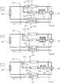
  • 1 ein aus dem Stand der Technik bekanntes Mehrfachstecksystem;
  • 2 ein Ausführungsbeispiel einer Steckkontaktvorrichtung mit einem Hauptkontakt und einem Hilfskontakt mit elektronischer Schalteinheit;
  • 3 ein zweites Ausführungsbeispiel einer Steckkontaktvorrichtung mit einem Hauptkontakt und einem Hilfskontakt mit elektronischer Schalteinheit;
  • 4A bis4C einen beispielhaften Trennvorgang eines Ausführungsbeispiels der Steckkontaktvorrichtung;
  • 5 ein drittes Ausführungsbeispiel der Steckkontaktvorrichtung als beispielhaftes Mehrfachstecksystem; und
  • 6A und6B zwei Ausführungsbeispiele einer bidirektionalen elektronischen Schalteinheit.
Further features and advantages of the invention are described below with reference to the accompanying drawings. Show it:
  • 1 a multiple connector system known from the prior art;
  • 2 an embodiment of a plug contact device with a main contact and an auxiliary contact with an electronic switching unit;
  • 3 a second embodiment of a plug contact device with a main contact and an auxiliary contact with an electronic switching unit;
  • 4A to 4C an exemplary separation process of an embodiment of the plug contact device;
  • 5 a third embodiment of the plug contact device as an exemplary multiple plug system; and
  • 6A and 6B two embodiments of a bidirectional electronic switching unit.

1 zeigt schematisch ein aus dem DokumentEP 2 742 565 B1 bekanntes mechatronisches Mehrfachstecksystem. Das Mehrfachstecksystem umfasst mindestens zwei Steckverbinder S1, S2 ..., die jeweils einen Hauptkontakt8 mit einem Hauptsteckkontakt und mit einem Hauptgegenkontakt sowie jeweils einen dem Hauptkontakt8 bei einem Aussteckvorgang nacheilenden Hilfskontakt9 mit einem Hilfssteckkontakt und mit einem Hilfsgegenkontakt aufweisen. Ferner umfasst das Mehrfachstecksystem des Dokuments EP2 742 565 B1 zur Löschung eines im Zuge eines Aussteckvorgangs entstehenden Lichtbogens eine einzige, den Steckverbindern S1, S2 ... gemeinsame Halbleiterelektronik10, die mit dem Hilfskontakt9 jedes Steckverbinders S1, S2 ... über eine Diode17 zur Vermeidung eines Kurzschlusses, beispielsweise der Steckverbinder S2 und S3, im Zuge eines Aussteckvorgangs eines oder mehrerer einzelner Steckverbinder, beispielsweise S1, in Reihe geschaltet ist, und wobei die Halbleiterelektronik10 zwei in Reihe geschaltete Halbleiterschalter und einen mit den Halbleiterschaltern verbundenen Energiespeicher aufweist, der zum Aufladen die im Zuge des Aussteckvorgangs entstehende Lichtbogenspannung zwischen den Halbleiterschaltern abgreift.1 shows schematically one from thedocument EP 2 742 565 B1 well-known mechatronic multiple connector system. The multiple connector system comprises at least two connectors S1 , S2 ..., each with a main contact 8th with a main plug contact and with a main mating contact and one each to the main contact 8th auxiliary contact lagging when unplugging 9 have with an auxiliary plug contact and with an auxiliary mating contact. The multiple connector system of document EP also includes 2 742 565 B1 a single semiconductor electronics commonto the plug-in connectors S 1 , S2 ... to extinguish an electric arc that occurs in the course of anunplugging process 10 that with the auxiliary contact 9 each connector S1 , S2 ... via a diode 17th to avoid a short circuit, for example the plug connector S2 and S3 , one or more individual plug connectors, for example S1 , are connected in series in the course of an unplugging process, and thesemiconductor electronics 10 has two series-connected semiconductor switches and an energy store connected to the semiconductor switches, which taps off the arc voltage between the semiconductor switches for charging during the unplugging process.

2 zeigt ein Ausführungsbeispiel einer allgemein mit Bezugszeichen100 bezeichneten Steckkontaktvorrichtung zur Vermeidung oder Löschung eines Lichtbogens beim Trennen oder Schließen einer Gleichstromverbindung. Die Steckkontaktvorrichtung100 umfasst einen allgemein mit Bezugszeichen110 bezeichneten Steckverbinder mit einem Hauptkontakt (HA)112 mit einer als Buchsenkontakt ausgebildeten ersten Kontakthälfte (HA1) 112-1 und einer als Stiftkontakt ausgebildeten zweiten Kontakthälfte (HA2) 112-2. Ferner umfasst der Steckverbinder110 einen Hilfskontakt (HI)114 mit einer als Buchsenkontakt ausgebildeten ersten Kontakthälfte (HI1) 114-1 und einer als Stiftkontakt ausgebildeten zweiten Kontakthälfte (HI2) 114-2. Die HA2 112-2 und HI2 114-2 sind elektrisch leitend verbunden. Eine elektronische Schalteinheit120 ist über einen ersten Anschluss122 parallel zum Buchsenkontakt (HA1) 112-1 geschaltet. Der HI114 ist über einen zweiten Anschluss124 in Reihe geschaltet mit der elektronischen Schalteinheit120. Die Steckkontaktvorrichtung100 ist in2 im zusammengesteckten ZustandT0 gezeigt, in dem der Stiftkontakt (HA2) 112-2 mit dem Buchsenkontakt (HA1) 112-1 über die Kontaktstelle113 elektrisch leitend verbunden ist. Der Stiftkontakt (HI2) 114-2 ist im in2 gezeigten zusammengesteckten ZustandT0 durch einen Trennabschnitt117, der eine umlaufende Isolierung umfasst, von der Kontaktstelle115 des Buchsenkontakts (HI1) 114-1 galvanisch getrennt.2 Figure 11 shows an embodiment of one generally withreference numerals 100 designated plug contact device to avoid or extinguish an arc when separating or closing a direct current connection. Theplug contact device 100 includes a generally numbered 110 designated connector with a main contact (HA) 112 with a first contact half (HA1) 112-1 designed as a socket contact and a second contact half (HA2) 112-2 designed as a pin contact. The connector also includes 110 an auxiliary contact (HI) 114 with a first contact half (HI1) 114-1 designed as a socket contact and a second contact half (HI2) 114-2 designed as a pin contact. The HA2 112-2 and HI2 114-2 are electrically connected. Anelectronic switching unit 120 is via afirst connection 122 connected in parallel to socket contact (HA1) 112-1. TheHI 114 is via asecond connection 124 connected in series with theelectronic Switching unit 120 . Theplug contact device 100 is in 2 when assembled T0 shown in which the pin contact (HA2) 112-2 with the socket contact (HA1) 112-1 via thecontact point 113 is electrically connected. The pin contact (HI2) 114-2 is in the in 2 shown assembled state T0 through apartition 117 , which comprises a circumferential insulation, from thecontact point 115 of the socket contact (HI1) 114-1 galvanically isolated.

Die elektronische Schalteinheit120 in2 umfasst ein RC-Glied („Resistor Capacitor“). Das RC-Glied kann als Metall-Oxid-Halbleiter-Feldeffekttransistor (MOSFET) oder Bipolartransistor mit isolierter Gate-Elektrode (IGBT) ausgebildet sein. Alternativ oder ergänzend können auch mehrere RC-Glieder, beispielsweise ein IGBT und ein MOSFET, in Reihe geschaltet sein. Optional umfasst die elektronische Schalteinheit ferner eine Gleichrichterbrücke (nicht gezeigt), die einen bidirektionalen Stromfluss in dem Gleichstromsystem ermöglicht. Durch eine Umkehr der Stromrichtung kann beispielsweise Bremsenergie einer generatorisch betriebenen Elektromaschine rekuperiert werden.Theelectronic switching unit 120 in 2 includes an RC element ("Resistor Capacitor"). The RC element can be designed as a metal-oxide-semiconductor field effect transistor (MOSFET) or a bipolar transistor with an insulated gate electrode (IGBT). As an alternative or in addition, several RC elements, for example an IGBT and a MOSFET, can also be connected in series. Optionally, the electronic switching unit further comprises a rectifier bridge (not shown), which enables a bidirectional current flow in the direct current system. By reversing the direction of the current, braking energy from an electric machine operated as a generator can be recuperated, for example.

3 zeigt ein zweites Ausführungsbeispiel einer allgemein mit Bezugszeichen100 bezeichneten Steckkontaktvorrichtung zur Vermeidung oder Löschung eines Lichtbogens beim Trennen oder Schließen einer Gleichstromverbindung im zusammengesteckten Zustand To. Gleiche Komponenten der Steckkontaktvorrichtung wie in2 sind mit denselben Bezugszeichen bezeichnet. Der allgemein mit Bezugszeichen110 bezeichnete Steckverbinder in3 umfasst eine im Vergleich zu2 umgekehrte Zuordnung von Stiftkontakten und Buchsenkontakten zu den ersten und zweiten Kontakthälften des HA und des HI.3 Figure 3 shows a second embodiment of one generally withreference numerals 100 designated plug contact device for avoiding or extinguishing an arc when separating or closing a direct current connection in the mated state To. The same components of the plug contact device as in 2 are denoted by the same reference numerals. The general withreference numerals 110 designated connectors in 3 includes a versus 2 reverse assignment of pin contacts and socket contacts to the first and second contact halves of the HA and the HI.

In einem dritten Ausführungsbeispiel (ohne Figur) ist der allgemein mit Bezugszeichen110 bezeichnete Steckverbinder hermaphroditisch ausgebildet. In einer ersten Variante eines hermaphroditischen Steckverbinders110 umfasst die HA1 112-1 einen Buchsenkontakt wie in2 gezeigt und die HI1 114-1 einen Stiftkontakt wie in3 gezeigt. In einer zweiten Variante eines hermaphroditischen Steckverbinders110 umfasst die HA1 112-1 einen Stiftkontakt wie in3 gezeigt und die HI1 114-1 einen Buchsenkontakt wie in2 gezeigt.In a third exemplary embodiment (without the figure), the is generally given areference number 110 designated connector hermaphroditic. In a first variant of ahermaphroditic connector 110 the HA1 112-1 includes a socket contact as in 2 and the HI1 114-1 has a pin contact as shown in FIG 3 shown. In a second variant of ahermaphroditic connector 110 the HA1 112-1 comprises a pin contact as in FIG 3 and the HI1 114-1 has a socket contact as in 2 shown.

4A bis4C zeigen jeweils eine Steckkontaktvorrichtung100, deren Steckverbinder110 einen HA112, einen HI114, einen Gegenpolkontakt (GE)116 und einen Erdungskontakt (PE)118 umfasst. Der HI112 ist wie in2 gezeigt mit einer elektronischen Schalteinheit120 in Reihe geschaltet. Die ersten Kontakthälften HA1 der HA112 und HI1 der HI114 sind mit einem Pol, vorzugsweise dem Pluspol, einer Gleichstromquelle130 verbunden oder verbindbar, wobei der HI114 mit einer elektronischen Schalteinheit120 in Reihe geschaltet ist, welche mit dem HA112 elektrisch leitend verbunden ist. Die erste Kontakthälfte GE1 116-1 des Gegenpolkontakts (GE)116 ist mit einem zweiten Pol, vorzugsweise dem Minuspol, der Gleichstromquelle130 verbunden oder verbindbar. Ferner umfasst der Steckverbinder110 in den4A bis4C einen Erdungskontakt (PE)118 mit erster Kontakthälfte (PE1) 118-1 und zweiter Kontakthälfte (PE2) 118-2. Die zweiten Kontakthälften HA2 112-2, HI2 114-2 und GE2 116-2 sind mit einer Last140 verbunden.4A to 4C each show aplug contact device 100 , their connectors 110 aHA 112 , aHI 114 , an opposite pole contact (GE) 116 and a ground contact (PE) 118 includes. TheHI 112 is like in 2 shown with anelectronic switching unit 120 connected in series. The first contact halves HA1 of theHA 112 and HI1 theHI 114 are connected to one pole, preferably the positive pole, of a directcurrent source 130 connected or connectable, theHI 114 with anelectronic switching unit 120 is connected in series, which is connected to theHA 112 is electrically connected. The first contact half GE1 116-1 of the opposite pole contact (GE) 116 is connected to a second pole, preferably the negative pole, of the directcurrent source 130 connected or connectable. The connector also includes 110 in the 4A to 4C a ground contact (PE) 118 with first contact half (PE1) 118-1 and second contact half (PE2) 118-2. The second contact halves HA2 112-2, HI2 114-2 and GE2 116-2 are with aload 140 connected.

4A zeigt die Steckkontaktvorrichtung100 im zusammengesteckten ZustandT0. Die Kontakte HA112, GE116 und PE118 sind elektrisch leitend verbunden. Der Kontakt HI114 ist mittels des Trennabschnitts117, beispielsweise einer umlaufenden Isolierung, galvanisch getrennt. Die Pluspolseite der Steckkontaktvorrichtung100 in4A stimmt mit derjenigen in2 überein.4A shows theplug contact device 100 when assembled T0 . Thecontacts HA 112 ,GE 116 andPE 118 are electrically connected. ContactHI 114 is by means of theseparating section 117 , for example a circumferential insulation, galvanically isolated. The positive pole side of theplug contact device 100 in 4A agrees with the one in 2 match.

4B zeigt die Steckkontaktvorrichtung100 im ersten ZwischenzustandT1, beispielsweise beim Trennen der Gleichstromverbindung, wobei der Steckverbinder110 nicht mehr vollständig zusammengesteckt ist. Die HA2 112-2 ist weiterhin elektrisch leitend mit der HA1 112-1 über die Kontaktstelle113 verbunden. Die HI2 114-2 ist nun mit der HI1 114-1 über die Kontaktstelle115 leitend verbunden. Die elektronische Schalteinheit120 ist im ersten ZwischenzustandT1 passiv. Insbesondere kann der Widerstand des RC-Glieds der elektronischen Schalteinheit120 im ersten ZwischenzustandT1 hochohmig sein.4B shows theplug contact device 100 in the first intermediate state T1 , for example when disconnecting the DC connection, with theconnector 110 is no longer fully plugged together. The HA2 112-2 is still electrically conductive with the HA1 112-1 via thecontact point 113 connected. The HI2 114-2 is now over the contact point with the HI1 114-1 115 conductively connected. Theelectronic switching unit 120 is in the first intermediate state T1 passive. In particular, the resistance of the RC element of theelectronic switching unit 120 in the first intermediate state T1 be high resistance.

4C zeigt die Steckkontaktvorrichtung100 im zweiten ZwischenzustandT2, in dem der Steckverbinder110 noch nicht vollständig getrennt ist. Der HA112 ist nun galvanisch getrennt, indem die HA2 112-2 räumlich von der Kontaktstelle113 getrennt ist. Zwischen der HA2 112-2 und der Kontaktstelle113 der HA1 112-1 entsteht ein Lichtbogen. Über den ersten Anschluss122 wird die elektronische Schalteinheit120 aktiviert. Die Aktivierung bewirkt, dass die elektronische Schalteinheit120 (oder ihr RC-Glied) leitend wird. Insbesondere kann das RC-Glied in dem zweiten ZwischenzustandT2 niederohmig sein. Die HI114 ist weiter über die Kontaktstelle115 leitend verbunden. Der Gleichstrom fließt nun von der Gleichstromquelle130 aus über die elektronische Schalteinheit120 und den HI114. Vorzugsweise umfasst die elektronische Schalteinheit120 ein Zeitglied, welches bewirkt, dass der Stromfluss über den HI114 nach einer vorbestimmten Zeitspanne unterbrochen wird. Die Unterbrechung des Stromflusses kann zeitlich vor einer galvanischen Trennung der HI114, GE116 und PE118 erfolgen.4C shows theplug contact device 100 in the second intermediate state T2 in which theconnector 110 is not yet completely separated. TheHA 112 is now galvanically separated by moving the HA2 112-2 spatially from thecontact point 113 is separated. Between the HA2 112-2 and thecontact point 113 the HA1 112-1 creates an arc. About thefirst connection 122 becomes theelectronic switching unit 120 activated. Activation causes the electronic switching unit 120 (or its RC element) becomes conductive. In particular, the RC element can be in the second intermediate state T2 be low resistance. TheHI 114 is further via thecontact point 115 conductively connected. The direct current now flows from the directcurrent source 130 from theelectronic switching unit 120 and theHI 114 . The electronic switching unit preferably comprises 120 a timer which causes the current to flow through theHI 114 is interrupted after a predetermined period of time. The interruption of the current flow can take place before a galvanic separation of theHI 114 ,GE 116 andPE 118 respectively.

In einem optionalen (nicht gezeigten) dritten Zwischenzustand sind die Kontakte HA112, HI114 und GE116 galvanisch getrennt, während der Erdungskontakt PE118 noch elektrisch leitend verbunden ist. Im (nicht gezeigten) gelösten Zustand T3 sind alle Kontakte HA112, HI114, GE116 und PE118 galvanisch getrennt. In dem gelösten Zustand T3 können die beiden Kontakthälften110-1 und110-2 des Steckverbinders110 räumlich getrennt sein.The contacts HA are in an optional third intermediate state (not shown) 112 ,HI 114 andGE 116 galvanically isolated, while the grounding contact isPE 118 is still electrically connected. In the released state T3 (not shown), all contacts areHA 112 ,HI 114 ,GE 116 andPE 118 galvanically isolated. In the released state T3 , the two contact halves 110-1 and 110-2 of theconnector 110 be spatially separated.

5 zeigt eine Steckkontaktvorrichtung100 mit drei Steckverbindern110. Jeder Steckverbinder110 ist baugleich zu dem Steckverbinder110 gemäß4A und im zusammengesteckten Zustand To dargestellt. Jeder HI114 ist im zusammengesteckten Zustand To durch den Trennabschnitt117 galvanisch getrennt. Auf der Seite der Gleichstromquelle130 sind die HI114 aller Steckverbinder110 am Punkt126 parallelgeschaltet, so dass alle HI114 mit nur einer (gemeinsamen) elektronischen Schalteinheit120 über den zweiten Anschluss124 elektrisch leitend verbunden sind. Die (gemeinsame) elektronische Schalteinheit120 ist mit den am Punkt127 parallelgeschalteten HA112 aller Steckverbinder110 elektrisch leitend verbunden. Die GE118 aller Steckverbinder110 sind am Punkt128 parallelgeschaltet.5 shows aplug contact device 100 with threeconnectors 110 . Everyconnector 110 is identical to theconnector 110 according to 4A and shown in the assembled state To. EveryHI 114 is in the assembled state To through theseparating section 117 galvanically isolated. On the side of theDC power source 130 are theHI 114 allconnectors 110 at thepoint 126 connected in parallel so that allHI 114 with only one (common)electronic switching unit 120 via thesecond connection 124 are electrically connected. The (common)electronic switching unit 120 is on point with them 127 HA connected in parallel 112 allconnectors 110 electrically connected. TheGE 118 allconnectors 110 are onpoint 128 connected in parallel.

Wird ein erster der Steckverbinder110 getrennt, so wird wie mit Bezug auf4A bis4C beschrieben der zugehörige HI114 in die leitenden ersten und zweiten ZwischenzuständeT1 undT2 überführt und eine Verbindung mit der elektronischen Schalteinheit120 hergestellt. Die Steckverbinder110 in den anderen (zusammengesteckten) Strängen sind von der Trennung des ersten Steckverbinders110 und dem resultierenden Lichtbogen im zugehörigen HA112 sowie Stromfluss im zugehörigen HI114 nicht betroffen, da ihre jeweiligen HI114 weiterhin galvanisch von der (gemeinsamen) elektronischen Schalteinheit120 getrennt sind. Es gibt im Normalbetrieb also keinen Kurzschluss zwischen verschiedenen Strängen. Wie in dem Patent von ETA besteht weiterhin eine Problematik analog zu der in der PatentschriftEP 2 742 565 B1 beschriebenen nur, wenn mehr als ein Steckverbinder110 gleichzeitig getrennt werden können. Werden zwei (oder mehr) Steckverbinder110 gleichzeitig gezogen, so kann ein Kurzschluss zwischen diesen beiden (oder mehr) Strängen auftreten.Becomes a first of theconnectors 110 separated, so as with reference to 4A to 4C described thecorresponding HI 114 into the conductive first and second intermediate states T1 and T2 transferred and a connection with theelectronic switching unit 120 produced. Theconnectors 110 in the other (plugged together) strands are from the separation of thefirst connector 110 and the resulting arc in the associatedHA 112 as well as current flow in the associatedHI 114 not affected as theirrespective HI 114 furthermore galvanically from the (common)electronic switching unit 120 are separated. In normal operation there is no short circuit between different strings. As in the ETA patent, there is still a problem analogous to that in thepatent specification EP 2 742 565 B1 described only if more than oneconnector 110 can be separated at the same time. Will be two (or more)connectors 110 pulled at the same time, a short circuit can occur between these two (or more) strands.

Die Ausführungsbeispiele der4A bis4C und5 weisen Buchsenkontakte als112-1, HI1114-1, GE1116-1 und PE1118-1 und Stiftkontakte als HA2112-2, HI112-2, GE2116-2 und PE2118-2 auf. Weitere (nicht gezeigte) Ausführungsbeispiele entsprechen der Vertauschung von Stiftkontakten und Buchsenkontakten wie in3. Ferner sind beliebige hermaphrodite Kombinationen der Steckverbinderhälften möglich.The embodiments of 4A to 4C and 5 assign socket contacts as 112-1 , HI1 114-1 , GE1 116-1 and PE1 118-1 and pin contacts as HA2 112-2 , HI 112-2 , GE2 116-2 and PE2 118-2 on. Further exemplary embodiments (not shown) correspond to the interchanging of pin contacts and socket contacts as in FIG 3 . Furthermore, any hermaphrodite combinations of the connector halves are possible.

Durch die Steckkontaktvorrichtung100, insbesondere durch den Trennabschnitt117 des Hilfskontakts HI114, können weitere Bauteile, insbesondere Dioden in oder an der ersten Kontakthälfte HI1114-1, vermieden werden.Through theplug contact device 100 , in particular by theseparating section 117 ofauxiliary contact HI 114 , further components, in particular diodes in or on the first contact half HI1 114-1 , be avoided.

Das (beispielsweise im Ausführungsbeispiel der5 gezeigte) Mehrfachstecksystem kann auf Gebäudeinstallationsebene hoch skaliert werden. Die elektronische Schalteinheit (beispielsweise die Schalteinheit120) wird dementsprechend nicht in einem Mehrfachstecksystem integriert, sondern beispielsweise zentral in einer Unterverteilung eines Raumes oder einer Etage. Daher muss der beschriebene Hilfskontakt (beispielsweise HI114) über eine zusätzliche Leitung mit der elektronischen Schalteinheit (beispielsweise Schalteinheit120) verbunden werden. Da es sich nicht um eine Steuerleitung oder Signalleitung handelt, kann diese Verbindung auch als X-Leiter bezeichnet werden.The (for example in the embodiment of 5 The multiple connector system shown can be scaled up to the building installation level. The electronic switching unit (for example the switching unit 120 ) is accordingly not integrated in a multiple plug-in system, but, for example, centrally in a sub-distribution of a room or a floor. Therefore the described auxiliary contact (e.g. HI 114 ) via an additional line to the electronic switching unit (e.g. switching unit 120 ) get connected. Since it is not a control line or a signal line, this connection can also be referred to as an X conductor.

6A und6B zeigen zwei Ausführungsbeispiele einer bidirektionalen elektronischen Schalteinheit120, die eine Gleichrichterbrücke umfasst. Die Gleichrichterbrücke ist über einen ersten Anschluss122 mit der HA1112-1 und über einen zweiten Anschluss124,224 mit der HI1114-1 verbindbar.6A and 6B show two exemplary embodiments of a bidirectionalelectronic switching unit 120 which includes a rectifier bridge. The rectifier bridge is over afirst connection 122 with the HA1 112-1 and asecond connection 124 , 224 with the HI1 114-1 connectable.

Die beiden weiteren (inneren) Anschlüsse der Gleichrichterbrücke sind im in6A gezeigten Ausführungsbeispiel über eine Parallelschaltung eines Halbleiterschalters und eines RC-Glieds mit variablem Widerstand miteinander verbunden, wobei die Impedanz des Halbleiterschalters mittels eines Steuersignals (gestrichelt gezeichnet) geändert werden kann. Über die Dioden der Gleichrichterbrücke wird unabhängig von einer außen (an dem ersten und zweiten Anschluss) anliegenden Polarität an den (beiden weiteren) inneren Anschlüssen eine spezifische Polarität sichergestellt und ein bidirektionaler Stromfluß durch den HA112 und den HI114 ermöglicht.The two other (inner) connections of the rectifier bridge are in the in 6A The embodiment shown is connected to one another via a parallel connection of a semiconductor switch and an RC element with a variable resistance, the impedance of the semiconductor switch being able to be changed by means of a control signal (shown in dashed lines). A specific polarity and a bidirectional current flow through the HA are ensured via the diodes of the rectifier bridge, regardless of a polarity applied externally (at the first and second connection) at the (two further)inner connections 112 and theHI 114 enables.

In dem in6B gezeigten Ausführungsbeispiel umfasst die elektronische Schalteinheit120 einen Verpolschutz, der zwei in entgegengesetzter Richtung miteinander in Reihe geschalteten Halbleiterschalter und jeweils eine in Sperrrichtung parallel geschaltete Diode umfasst (links in6B). Die jeweils parallel geschaltete Diode wirkt in Sperrrichtung des Halbleiterschalters als Bypass. Ferner umfasst die elektronische Schalteinheit120 in6B einen Trigger-Schaltkreis, der die beiden weiteren (inneren) Anschlüsse der Gleichrichterbrücke (rechts in6B) verbindet. Der Trigger-Schaltkreis verändert (z.B. verringert) abhängig von einer außen anliegenden Polarität die Impedanz eines oder beider der zwei in Reihe geschalteten Halbleiterschalter mittels (gestrichelt dargestellter) Steuersignale. Alternativ kann auch ein unipolarer Halbleiterschalter verwendet werden.In the in 6B The embodiment shown includes theelectronic switching unit 120 polarity reversal protection, which comprises two semiconductor switches connected in series with one another in opposite directions and one diode each connected in parallel in reverse direction (left in 6B) . The diode connected in parallel acts as a bypass in the reverse direction of the semiconductor switch. Furthermore, the electronic switching unit comprises 120 in 6B a trigger circuit that connects the other two (inner) connections of the rectifier bridge (right in 6B) connects. The trigger circuit changes (eg reduces) the impedance of one or both of the two series-connected semiconductor switches by means of control signals (shown in dashed lines) depending on an externally applied polarity. Alternatively can a unipolar semiconductor switch can also be used.

Die Zuleitung zu der elektronischen Schalteinheit (beispielsweise Schalteinheit120) zu verlängern, ist für jemanden mit technischem Hintergrund womöglich noch offensichtlich und stellt für sich alleine keine technische Neuerung dar. Jedoch muss im Stand der Technik, beispielsweise in der PatentschriftEP 2 742 565 B1, jeder Steckverbinder (beispielsweise bestehend aus gleichstromquellenseitiger Buchseneinheit4 und lastenseitiger Steckereinheit5) mit einer Diode7, entweder im Steckverbinder, oder zumindest irgendwo in der (als Steuerleitung ausgebildeten) Hilfsleitung ausgestattet werden. In der erfindungsgemäßen Steckkontaktvorrichtung100 werden diese Dioden durch eine sichere galvanische Trennung in den Hilfskontakten (beispielsweise den HI114) ersetzt. Der Hilfskontakt (beispielsweise HI114) weist dazu einen (isolierenden) Trennabschnitt117 auf, der im zusammengesteckten Zustand die metallischen Kontaktpartner von Stiftkontakt und Buchsenkontakt voneinander trennt. Die Ausgestaltung in Form von rundem Stift und runder Buchse ist dabei nur exemplarisch. So ein Isolator kann auch bei hermaphroditischen Kontakten oder bei Flachkontakten eingesetzt werden. Da im zusammengesteckten Zustand die Hilfskontakte (beispielsweise HI114) aller Steckverbinder (beispielsweise Steckverbinder110) auf dem jeweiligen (isolierten) Trennabschnitt117 der Hilfskontakte in Ruheposition sind, kann somit auch kein Kurzschluss zwischen verschiedenen Steckverbindern entstehen. Erst beim Trennvorgang eines Steckverbinders wird eine leitende Verbindung zu der elektronischen Schalteinheit (beispielsweise der Schalteinheit120) hergestellt.The lead to the electronic switching unit (for example switching unit 120 ) may still be obvious to someone with a technical background and does not in itself constitute a technical innovation. However, in the state of the art, for example in thepatent EP 2 742 565 B1 , each connector (for example, consisting of a socket unit on the DC power source 4th and load-side connector unit 5 ) with a diode 7th , either in the connector, or at least somewhere in the auxiliary line (designed as a control line). In the plug contact device according to theinvention 100 are these diodes through a safe galvanic isolation in the auxiliary contacts (for example the HI 114 ) replaced. The auxiliary contact (e.g. HI 114 ) has an (insulating) separating section for thispurpose 117 which separates the metallic contact partners of the pin contact and socket contact from each other when plugged together. The design in the form of a round pin and a round socket is only an example. Such an insulator can also be used for hermaphroditic contacts or for flat contacts. Since the auxiliary contacts (e.g. HI 114 ) of all connectors (e.g. connectors 110 ) on the respective (isolated)separating section 117 the auxiliary contacts are in the rest position, there can be no short-circuit between different connectors. A conductive connection to the electronic switching unit (for example the switching unit 120 ) produced.

Obwohl die Erfindung in Bezug auf exemplarische Ausführungsbeispiel beschrieben worden ist, ist es für einen Fachmann ersichtlich, dass verschiedene Änderungen vorgenommen werden können und Äquivalente als Ersatz verwendet werden können. Ferner können viele Modifikationen vorgenommen werden, um eine bestimmte Situation oder ein bestimmtes Material an die Lehre der Erfindung anzupassen. Folglich ist die Erfindung nicht auf die offenbarten Ausführungsbeispiele beschränkt, sondern umfasst alle Ausführungsbeispiele, die in den Bereich der beigefügten Patentansprüche fallen.Although the invention has been described with reference to exemplary embodiments, it will be apparent to one skilled in the art that various changes can be made and equivalents used as replacements. Furthermore, many modifications can be made to adapt a particular situation or material to the teachings of the invention. Consequently, the invention is not limited to the disclosed exemplary embodiments, but rather encompasses all exemplary embodiments that fall within the scope of the appended claims.

BezugszeichenlisteList of reference symbols

22
DC-QuelleDC source
33
Lastload
44th
BuchseneinheitSocket unit
55
SteckereinheitConnector unit
66th
HinleiterOutward ladder
77th
RückleiterReturn conductor
88th
HauptkontaktMain contact
99
HilfskontaktAuxiliary contact
1010
Elektronikelectronics
11, 1211, 12
Bypass/-leitungBypass / line
1313th
Dritter KontaktThird contact
14, 15, 1614, 15, 16
Leitungmanagement
1717th
Diodediode
100100
SteckkontaktvorrichtungPlug contact device
110110
SteckverbinderConnectors
110-1110-1
Erste SteckverbinderhälfteFirst connector half
110-2110-2
Zweite SteckverbinderhälfteSecond connector half
112112
HauptkontaktMain contact
112-1112-1
Erste Kontakthälfte des HauptkontaktsFirst contact half of the main contact
112-2112-2
Zweite Kontakthälfte des HauptkontaktsSecond contact half of the main contact
113113
Kontaktstelle des HauptkontaktsContact point of the main contact
114114
HilfskontaktAuxiliary contact
114-1114-1
Erste Kontakthälfte des HilfskontaktsFirst contact half of the auxiliary contact
114-2114-2
Zweite Kontakthälfte des HilfskontaktsSecond contact half of the auxiliary contact
115115
Kontaktstelle des HilfskontaktsContact point of the auxiliary contact
116116
GegenpolkontaktOpposite pole contact
116-1116-1
Erste Kontakthälfte des GegenpolkontaktsFirst contact half of the opposite pole contact
116-2116-2
Zweite Kontakthälfte des GegenpolkontaktsSecond contact half of the opposite pole contact
117117
TrennabschnittSeparation section
118118
ErdungskontaktGround contact
118-1118-1
Erste Kontakthälfte des ErdungskontaktsFirst contact half of the earth contact
118-2118-2
Zweite Kontakthälfte des ErdungskontaktsSecond contact half of the earthing contact
120120
Elektronische SchalteinheitElectronic switching unit
122122
Erster AnschlussFirst connection
124124
Zweiter AnschlussSecond connection
126126
Parallelschaltung von HilfskontaktenParallel connection of auxiliary contacts
127127
Parallelschaltung von HauptkontaktenParallel connection of main contacts
128128
Parallelschaltung von GegenpolkontaktenParallel connection of opposite pole contacts
130130
GleichstromquelleDC power source
140140
Lastload
T0T0
Zusammengesteckter ZustandAssembled condition
T1T1
Erster ZwischenzustandFirst intermediate state
T2T2
Zweiter ZwischenzustandSecond intermediate state

ZITATE ENTHALTEN IN DER BESCHREIBUNGQUOTES INCLUDED IN THE DESCRIPTION

Diese Liste der vom Anmelder aufgeführten Dokumente wurde automatisiert erzeugt und ist ausschließlich zur besseren Information des Lesers aufgenommen. Die Liste ist nicht Bestandteil der deutschen Patent- bzw. Gebrauchsmusteranmeldung. Das DPMA übernimmt keinerlei Haftung für etwaige Fehler oder Auslassungen.This list of the documents listed by the applicant was generated automatically and is included solely for the better information of the reader. The list is not part of the German patent or utility model application. The DPMA assumes no liability for any errors or omissions.

Zitierte PatentliteraturPatent literature cited

  • EP 2742565 B1 [0004, 0005, 0006, 0040, 0051, 0058]EP 2742565 B1 [0004, 0005, 0006, 0040, 0051, 0058]
  • US 2018/0006447 A1 [0004, 0005]US 2018/0006447 A1 [0004, 0005]
  • DE 000010253749 A1 [0004]DE 000010253749 A1 [0004]
  • DE 102007043512 A1 [0004]DE 102007043512 A1 [0004]
  • EP 2742565 [0013]EP 2742565 [0013]

Claims (17)

Translated fromGerman
Steckkontaktvorrichtung (100) zur Vermeidung oder Löschung eines Lichtbogens beim Trennen oder Schließen einer Gleichstromverbindung, umfassend:mindestens einen Steckverbinder (110) mit jeweils einem Hauptkontakt, HA (112), und einem Hilfskontakt, HI (114), wobei der HA (112) eine erste Kontakthälfte, HA1 (112-1), und eine zweite Kontakthälfte, HA2 (112-2), umfasst, die lösbar zusammensteckbar sind, wobei der HA (112) dazu ausgebildet ist,- in einem zusammengesteckten Zustand (To) des jeweiligen Steckverbinders (110) die HA1 (112-1) und die HA2 (112-2) elektrisch leitend zu verbinden,- in einem gelösten Zustand des jeweiligen Steckverbinders (110) die HA1 (112-1) und die HA2 (112-2) galvanisch zu trennen,- in einem ersten Zwischenzustand (T1) des jeweiligen Steckverbinders (110) zwischen dem zusammengesteckten Zustand (T0) und dem gelösten Zustand die HA1 (112-1) und die HA2 (112-2) elektrisch leitend zu verbinden und- in einem zweiten Zwischenzustand (T2) des jeweiligen Steckverbinders (110) zwischen dem ersten Zwischenzustand (T1) und dem gelösten Zustand die HA1 (112-1) und die HA2 (112-2) galvanisch zu trennen,wobei der Hilfskontakt, HI (114), eine erste Kontakthälfte, Hl1 (114-1), und eine zweite Kontakthälfte, HI2 (114-2), umfasst, die lösbar zusammensteckbar sind, wobei der HI (114) dazu ausgebildet ist,- im zusammengesteckten Zustand (T0) des jeweiligen Steckverbinders die Hl1 (114-1) und die HI2 (114-2) galvanisch zu trennen,- im gelösten Zustand des jeweiligen Steckverbinders die Hl1 (114-1) und die HI2 (114-2) galvanisch zu trennen,- im ersten Zwischenzustand (T1) des jeweiligen Steckverbinders die Hl1 (114-1) und die HI2 (114-2) elektrisch leitend zu verbinden und- im zweiten Zwischenzustand (T2) des jeweiligen Steckverbinders die Hl1 (114-1) und die HI2 (114-2) elektrisch leitend zu verbinden, und wobei die HA2 (112-2) und die HI2 (114-2) elektrisch leitend verbunden sind; und eine elektronische Schalteinheit (120), deren erster Anschluss (122) mit der HA1 (112-1) und deren zweiter Anschluss (124) mit der Hl1 (114-1) elektrisch leitend verbunden sind, wobei die elektronische Schalteinheit (120) dazu ausgebildet ist, in Reaktion auf einen Übergang vom zusammengesteckten Zustand (T0) in den ersten Zwischenzustand (T1) den ersten Anschluss (122) und den zweiten Anschluss (124) elektrisch leitend zu verbinden oder eine Impedanz zwischen dem ersten Anschluss (122) und dem zweiten Anschluss (124) zu verkleinern, und in Reaktion auf einen Übergang vom ersten Zwischenzustand (T1) in den zweiten Zwischenzustand (T2) und/oder vom zweiten Zwischenzustand (T2) in den gelösten Zustand den ersten Anschluss (122) und den zweiten Anschluss (124) elektrisch zu trennen oder eine Impedanz zwischen dem ersten Anschluss (122) und dem zweiten Anschluss (124) zu vergrößern.Plug contact device (100) for avoiding or extinguishing an electric arc when separating or closing a direct current connection, comprising: at least one plug connector (110) each with a main contact, HA (112), and an auxiliary contact, HI (114), the HA (112) a first contact half, HA1 (112-1), and a second contact half, HA2 (112-2), which can be releasably plugged together, the HA (112) being designed to - in a plugged together state (To) of the respective Connector (110) to connect the HA1 (112-1) and the HA2 (112-2) in an electrically conductive manner, - in a released state of the respective connector (110) the HA1 (112-1) and the HA2 (112-2) galvanically isolate, - in a first intermediate state (T1 ) of the respective connector (110) between theplugged-together state (T 0 ) and the released state, the HA1 (112-1) and the HA2 (112-2) to be connected in an electrically conductive manner and - in a second intermediate state (T2 ) of the respective Ste connector (110) to galvanically separate the HA1 (112-1) and the HA2 (112-2) between the first intermediate state (T1 ) and the released state, the auxiliary contact, HI (114), a first contact half, Hl1 ( 114-1), and a second contact half, HI2 (114-2), which can be detachably plugged together, the HI (114) being designed to - inthe plugged-together state (T 0 ) of the respective connector, the Hl1 (114- 1) and electrically isolate the HI2 (114-2), - galvanically isolate the Hl1 (114-1) and the HI2 (114-2) in the released state of the respective connector, - in the first intermediate state (T1 ) of the respective connector Connector to connect the Hl1 (114-1) and the HI2 (114-2) in an electrically conductive manner and - in the second intermediate state (T2 ) of the respective connector, the Hl1 (114-1) and the HI2 (114-2) to be electrically conductive connect, and wherein the HA2 (112-2) and the HI2 (114-2) are electrically connected; and an electronic switching unit (120) whose first connection (122) is connected to the HA1 (112-1) and whose second connection (124) is electrically conductively connected to the Hl1 (114-1), the electronic switching unit (120) for this purpose is designed to connect the first connection (122) and the second connection (124) in an electrically conductive manner in response to a transition from the mated state (T0 ) to the first intermediate state (T1) or an impedance between the first connection (122) and shrink the second connection (124), and in response to a transition from the first intermediate state (T1 ) to the second intermediate state (T2 ) and / or from the second intermediate state (T2 ) to the released state, the first connection (122 ) and electrically isolating the second connection (124) or increasing an impedance between the first connection (122) and the second connection (124).Steckkontaktvorrichtung (100) nachAnspruch 1, wobei die elektronische Schalteinheit (120) ferner dazu ausgebildet ist, in Reaktion auf einen Übergang vom gelösten Zustand in den zweiten Zwischenzustand (T2) und/oder vom zweiten Zwischenzustand (T2) in den ersten Zwischenzustand (T1) den ersten Anschluss (122) und den zweiten Anschluss (124) elektrisch leitend zu verbinden oder eine Impedanz zwischen dem ersten Anschluss (122) und dem zweiten Anschluss (124) zu verkleinern, und in Reaktion auf einen Übergang vom ersten Zwischenzustand (T1) in den zusammengesteckten Zustand (T0) den ersten Anschluss (122) und den zweiten Anschluss (124) elektrisch zu trennen oder eine Impedanz zwischen dem ersten Anschluss (122) und dem zweiten Anschluss (124) zu vergrößern.Plug contact device (100) according to Claim 1 , wherein the electronic switching unit (120) is further designed, in response to a transition from the released state to the second intermediate state (T2 ) and / or from the second intermediate state (T2 ) to the first intermediate state (T1 ), the first connection (122) and the second connection (124) to electrically conductively connect or to reduce an impedance between the first connection (122) and the second connection (124), and in response to a transition from the first intermediate state (T1 ) to the mated State (T0 ) to electrically separate the first connection (122) and the second connection (124) or to increase an impedance between the first connection (122) and the second connection (124).Steckkontaktvorrichtung (100) nachAnspruch 1 oder2, wobei der mindestens eine Steckverbinder (110) jeweils eine erste Steckverbinderhälfte (110-1) und eine zweite Steckverbinderhälfte (110-2) umfasst, und wobei die erste Steckverbinderhälfte (110-1) die HA1 (112-1) und die Hl1 (114-1) umfasst und die zweite Steckverbinderhälfte (110-2) die HA2 (112-2) und die HI2 (114-2) umfasst.Plug contact device (100) according to Claim 1 or 2 , wherein the at least one connector (110) each comprises a first connector half (110-1) and a second connector half (110-2), and wherein the first connector half (110-1) the HA1 (112-1) and the Hl1 ( 114-1) and the second connector half (110-2) comprises the HA2 (112-2) and the HI2 (114-2).Steckkontaktvorrichtung (100) nach einem derAnsprüche 1 bis3, wobei ein Pol einer Gleichstromquelle (130) der Gleichstromverbindung, vorzugsweise ein Pluspol der Gleichstromquelle (130), mit der HA1 (112-1) des Hauptkontakts (112) und/oder dem ersten Anschluss (122) der elektronischen Schalteinheit (120) elektrisch leitend verbunden oder verbindbar ist, und wobei ein Pol eines elektrischen Verbrauchers, vorzugsweise ein Pluspol des Verbrauchers, mit der HA2 (112-2) des Hauptkontakts (112) und/oder der HI2 (114-2) des Hilfskontakts (114) elektrisch leitend verbunden oder verbindbar ist; und/oder wobei ein Pol einer Gleichstromquelle (130) der Gleichstromverbindung, vorzugsweise ein Pluspol der Gleichstromquelle (130), mit der HA2 (112-2) des Hauptkontakts (112) und/oder der HI2 (114-2) des Hilfskontakts (114) elektrisch leitend verbunden oder verbindbar ist, und wobei ein Pol eines elektrischen Verbrauchers, vorzugsweise ein Pluspol des Verbrauchers, mit der HA1 (112-1) des Hauptkontakts (112) und/oder dem ersten Anschluss (122) der elektronischen Schalteinheit (120) elektrisch leitend verbunden oder verbindbar ist.Plug contact device (100) according to one of the Claims 1 to 3 , wherein a pole of a direct current source (130) of the direct current connection, preferably a positive pole of the direct current source (130), with the HA1 (112-1) of the main contact (112) and / or the first connection (122) of the electronic switching unit (120) electrically is conductively connected or connectable, and wherein one pole of an electrical load, preferably a positive pole of the load, is electrically conductive with the HA2 (112-2) of the main contact (112) and / or the HI2 (114-2) of the auxiliary contact (114) connected or connectable; and / or wherein a pole of a direct current source (130) of the direct current connection, preferably a positive pole of the direct current source (130), with the HA2 (112-2) of the main contact (112) and / or the HI2 (114-2) of the auxiliary contact (114 ) is electrically conductively connected or connectable, and wherein a pole of an electrical consumer, preferably a positive pole of the consumer, with the HA1 (112-1) of the main contact (112) and / or the first connection (122) of the electronic switching unit (120) is electrically connected or connectable.Steckkontaktvorrichtung (100) nach einem derAnsprüche 1 bis4, wobei die HA1 (112-1) einen Stiftkontakt und die HA2 (112-2) einen Buchsenkontakt umfasst, oder wobei die HA2 (112-2) einen Stiftkontakt und die HA1 (112-1) einen Buchsenkontakt umfasst; und/oder wobei die Hl1 (114-1) einen Stiftkontakt und die HI2 (114-2) einen Buchsenkontakt umfasst, oder wobei die HI2 (114-2) einen Stiftkontakt und die Hl1 (114-1) einen Buchsenkontakt umfasst.Plug contact device (100) according to one of the Claims 1 to 4th wherein the HA1 (112-1) comprises a pin contact and the HA2 (112-2) comprises a socket contact, or wherein the HA2 (112-2) comprises a pin contact and the HA1 (112-1) comprises a socket contact; and / or wherein the Hl1 (114-1) a Pin contact and the HI2 (114-2) comprises a socket contact, or wherein the HI2 (114-2) comprises a pin contact and the HI1 (114-1) comprises a socket contact.Steckkontaktvorrichtung nachAnspruch 5, wobei ein Außenprofil des Stiftkontakts und/oder ein Innenprofil des Buchsenkontakts des HA (112) und/oder ein Außenprofil des Stiftkontakts und/oder ein Innenprofil des Buchsenkontakts des HI (114) des jeweiligen Steckverbinders (110) einen runden, ovalen oder mehreckigen Querschnitt aufweist, und/oder wobei der HA (112) und der HI (114) des jeweiligen Steckverbinders (110) hermaphroditisch sind.Plug contact device according to Claim 5 , wherein an outer profile of the pin contact and / or an inner profile of the socket contact of the HA (112) and / or an outer profile of the pin contact and / or an inner profile of the socket contact of the HI (114) of the respective connector (110) has a round, oval or polygonal cross section and / or wherein the HA (112) and the HI (114) of the respective connector (110) are hermaphroditic.Steckkontaktvorrichtung (100) nach einem derAnsprüche 1 bis6, wobei der HA (112) und der HI (114) jeweils eine Längsachse aufweisen, und wobei die HA1 (112-1) und die HA2 (112-2) sowie die Hl1 (114-1) und die HI2 (114-2) jeweils entlang ihrer Längsachse zusammensteckbar und lösbar sind, oder wobei die HA1 (112-1) und die HA2 (112-2) und/oder die Hl1 (114-1) und die HI2 (114-2) jeweils entlang einer Querachse, die quer oder senkrecht zur Längsachse ist, zusammensteckbar und lösbar sind.Plug contact device (100) according to one of the Claims 1 to 6th , wherein the HA (112) and the HI (114) each have a longitudinal axis, and wherein the HA1 (112-1) and the HA2 (112-2) as well as the Hl1 (114-1) and the HI2 (114-2 ) are each pluggable and detachable along their longitudinal axis, or wherein the HA1 (112-1) and the HA2 (112-2) and / or the Hl1 (114-1) and the HI2 (114-2) each along a transverse axis, which is transverse or perpendicular to the longitudinal axis, can be plugged together and detached.Steckkontaktvorrichtung (100) nachAnspruch 7, wobei eine Ausdehnung der HI2 (114-2) oder der Hl1 (114-1) des HI (114) bezüglich einer Kontaktstelle (115) der Hl1 (114-1) bzw. HI2 (114-2), die der HI2 (114-2) oder der Hl1 (114-1) des jeweiligen HI (114) zugeordnet ist, länger ist als eine Ausdehnung der HA2 (112-2) oder der HA1 (112-1) des HA (112) bezüglich einer Kontaktstelle (113) der HA1 (112-1) bzw. HA2 (112-2), die der HA2 (112-2) oder der HA1 (112-1) des jeweiligen HA (112) zugeordnet ist, wobei die jeweilige Ausdehnung entlang der Längsachse in der Richtung des Zusammensteckens im zusammengesteckten Zustand bestimmt ist.Plug contact device (100) according to Claim 7 , an extension of the HI2 (114-2) or the Hl1 (114-1) of the HI (114) with respect to a contact point (115) of the Hl1 (114-1) or HI2 (114-2), which the HI2 ( 114-2) or the Hl1 (114-1) of the respective HI (114) is longer than an extension of the HA2 (112-2) or the HA1 (112-1) of the HA (112) with respect to a contact point ( 113) the HA1 (112-1) or HA2 (112-2), which is assigned to the HA2 (112-2) or the HA1 (112-1) of the respective HA (112), the respective extent along the longitudinal axis is determined in the mating direction in the mated state.Steckkontaktvorrichtung (100) nachAnspruch 7 oder8, wobei die HI2 (114-2) oder die HI1 (114-1) des HI (114) des mindestens einen Steckverbinders (110) einen Trennabschnitt (117) umfasst, und wobei der Trennabschnitt (117) im zusammengesteckten Zustand (To) des jeweiligen Steckverbinders (110) eine galvanische Trennung von der Kontaktstelle der HI1 (114-1) oder der HI2 (114-2), die der HI2 (114-2) oder der HI1 (114-1) des HI (114) zugeordnet ist, bewirkt.Plug contact device (100) according to Claim 7 or 8th , wherein the HI2 (114-2) or the HI1 (114-1) of the HI (114) of the at least one connector (110) comprises a separating section (117), and wherein the separating section (117) in the mated state (To) des respective connector (110) a galvanic separation from the contact point of the HI1 (114-1) or the HI2 (114-2), which is assigned to the HI2 (114-2) or the HI1 (114-1) of the HI (114) , causes.Steckkontaktvorrichtung (100) nachAnspruch 9, wobei eine Ausdehnung des Trennabschnitts (117) der HI2 (114-2) oder der HI1 (114-1) eine entlang einer Teilausdehnung der HI2 (114-2) bzw. HI1 (114-1) umlaufende Isolierung umfasst, und wobei die Teilausdehnung der HI2 (114-2) bzw. HI1 (114-1) kürzer ist als die Ausdehnung der HA2 (112-2) oder der HA1 (112-1) des HA (112) bezüglich einer Kontaktstelle (113) der HA1 (112-1) bzw. HA2 (112-2), die die HA2 (112-2) oder die HA1 (112-1) des jeweiligen HA (112) zugeordnet ist, wobei die jeweilige Ausdehnung entlang der Längsachse in der Richtung des Zusammensteckens im zusammengesteckten Zustand bestimmt ist.Plug contact device (100) according to Claim 9 , wherein an extension of the separating section (117) of the HI2 (114-2) or the HI1 (114-1) comprises a circumferential insulation along a partial extension of the HI2 (114-2) or HI1 (114-1), and wherein the Partial extent of HI2 (114-2) or HI1 (114-1) is shorter than the extent of HA2 (112-2) or HA1 (112-1) of HA (112) with respect to a contact point (113) of HA1 ( 112-1) or HA2 (112-2), which is assigned to the HA2 (112-2) or the HA1 (112-1) of the respective HA (112), the respective extension along the longitudinal axis in the direction of plugging together is determined in the assembled state.Steckkontaktvorrichtung (100) nachAnspruch 7 bis10, wobei die HA1 (112-1) oder die HA2 (112-1) des HA (112) entlang der Längsachse nur eine Kontaktstelle (113) aufweist und/oder die HI1 (114-1) oder die HI2 (114-2) des HI (114) entlang der Längsachse nur eine Kontaktstelle (115) aufweist.Plug contact device (100) according to Claim 7 to 10 , the HA1 (112-1) or the HA2 (112-1) of the HA (112) having only one contact point (113) along the longitudinal axis and / or the HI1 (114-1) or the HI2 (114-2) of the HI (114) has only one contact point (115) along the longitudinal axis.Steckkontaktvorrichtung (100) nach einem derAnsprüche 1 bis11, wobei die elektronische Schalteinheit (120) zum bidirektionalen Stromfluss zwischen dem ersten Anschluss (122) und dem zweiten Anschluss (124) ausgebildet ist.Plug contact device (100) according to one of the Claims 1 to 11 , wherein the electronic switching unit (120) is designed for bidirectional current flow between the first connection (122) and the second connection (124).Steckkontaktvorrichtung (100) nach einem derAnsprüche 1 bis12, wobei die elektronische Schalteinheit (120) mindestens einen Halbleiterschalter umfasst, der dazu ausgebildet ist, bei Anliegen einer elektrischen Spannung zwischen dem ersten Anschluss (122) und dem zweiten Anschluss (124) die Impedanz zwischen dem ersten Anschluss (122) und dem zweiten Anschluss (124) zu verkleinern oder den ersten Anschluss (122) und den zweiten Anschluss (124) elektrisch leitend zu verbinden.Plug contact device (100) according to one of the Claims 1 to 12th , wherein the electronic switching unit (120) comprises at least one semiconductor switch which is designed to reduce the impedance between the first connection (122) and the second connection when an electrical voltage is applied between the first connection (122) and the second connection (124) (124) or to connect the first connection (122) and the second connection (124) in an electrically conductive manner.Steckkontaktvorrichtung (100) nachAnspruch 12 und13, wobei die elektronische Schalteinheit (120) eine Gleichrichterbrücke umfasst, die mit dem mindestens einen Halbleiterschalter verkettet ist.Plug contact device (100) according to Claim 12 and 13th wherein the electronic switching unit (120) comprises a rectifier bridge which is linked to the at least one semiconductor switch.Steckkontaktvorrichtung (100) nachAnspruch 13 oder14, wobei die elektronische Schalteinheit (120) zwei in zueinander entgegengesetzter Richtung miteinander in Reihe geschaltete Halbleiterschalter umfasst, denen jeweils in Sperrrichtung eine Diode parallel geschaltet ist, optional wobei die elektronische Schalteinheit (120) ferner einen Trigger-Schaltkreis umfasst, der dazu ausgebildet ist, beim Anliegen der elektrischen Spannung zwischen dem ersten Anschluss (122) und dem zweiten Anschluss (124) ein Schließen eines Halbleiterschalters zu bewirken, optional wobei der Trigger-Schaltkreis die Gleichrichterbrücke umfasst.Plug contact device (100) according to Claim 13 or 14th , wherein the electronic switching unit (120) comprises two semiconductor switches connected in series with one another in opposite directions, each of which is connected in parallel with a diode in the reverse direction, optionally wherein the electronic switching unit (120) further comprises a trigger circuit which is designed to to cause a semiconductor switch to close when the electrical voltage is applied between the first connection (122) and the second connection (124), optionally wherein the trigger circuit comprises the rectifier bridge.Steckkontaktvorrichtung (100) nach einem derAnsprüche 1 bis15, wobei die Steckkontaktvorrichtung (100) mindestens zwei Steckverbinder (110) mit jeweils einem HA (112) und einem HI (114) und eine elektronische Schalteinheit (120) umfasst, und wobei der erste Anschluss (122) der elektronischen Schalteinheit (120) mit der HA1 (112-1) jedes HA (112) elektrisch leitend verbunden ist und der zweite Anschluss (124) der elektronischen Schalteinheit (120) mit der HI1 (114-1) jedes HI (114) elektrisch leitend verbunden ist.Plug contact device (100) according to one of the Claims 1 to 15th , wherein the plug contact device (100) comprises at least two plug connectors (110) each with an HA (112) and a HI (114) and an electronic switching unit (120), and wherein the first connection (122) of the electronic switching unit (120) with the HA1 (112-1) of each HA (112) is electrically conductively connected and the second connection (124) of the electronic switching unit (120) is electrically conductively connected to the HI1 (114-1) of each HI (114).Steckkontaktvorrichtung (100) nach einem derAnsprüche 1 bis16, wobei der mindestens eine Steckverbinder (110) ferner einen Gegenpolkontakt, GE (116), mit einer ersten Kontakthälfte, GE1 (116-1), und einer zweite Kontakthälfte, GE2 (116-2), umfasst für einen Gegenpol der Gleichstromverbindung bezüglich des HA (112), vorzugsweise wobei der GE (116) dazu ausgebildet ist, im zusammengesteckten Zustand (T0) des jeweiligen Steckverbinders, im ersten Zwischenzustand (T1) des jeweiligen Steckverbinders und im zweiten Zwischenzustand (T2) des jeweiligen Steckverbinders die GE1 (116-1) und die GE2 (116-2) elektrisch leitend zu verbinden.Plug contact device (100) according to one of the Claims 1 to 16 , wherein the at least one connector (110) further comprises an opposite pole contact, GE (116), with a first contact half, GE1 (116-1), and a second contact half, GE2 (116-2), for an opposite pole of the direct current connection with respect to the HA (112), preferably wherein the GE (116) is designed to handle the GE1 in the matedstate (T 0 ) of the respective connector, in the first intermediate state (T1 ) of the respective connector and in the second intermediate state (T2) of the respective connector (116-1) and the GE2 (116-2) to be connected in an electrically conductive manner.
DE102019135128.6A2019-12-192019-12-19 Plug-in contact device to avoid an electric arc when disconnecting a direct current connectionWithdrawnDE102019135128A1 (en)

Priority Applications (6)

Application NumberPriority DateFiling DateTitle
DE102019135128.6ADE102019135128A1 (en)2019-12-192019-12-19 Plug-in contact device to avoid an electric arc when disconnecting a direct current connection
JP2022537690AJP7398564B2 (en)2019-12-192020-12-16 Plug-in contact device to avoid arcing when disconnecting direct current connections
US17/785,454US20230178925A1 (en)2019-12-192020-12-16Plug-in contact apparatus for preventing an arc when disconnecting a dc connection
EP20833789.9AEP4078737B1 (en)2019-12-192020-12-16Plug-in contact apparatus for preventing an arc when disconnecting a dc connection
CN202080088329.1ACN114830461B (en)2019-12-192020-12-16Plug-in contact for preventing arcing during disconnection of a DC connection
PCT/EP2020/086513WO2021122811A1 (en)2019-12-192020-12-16Plug-in contact apparatus for preventing an arc when disconnecting a dc connection

Applications Claiming Priority (1)

Application NumberPriority DateFiling DateTitle
DE102019135128.6ADE102019135128A1 (en)2019-12-192019-12-19 Plug-in contact device to avoid an electric arc when disconnecting a direct current connection

Publications (1)

Publication NumberPublication Date
DE102019135128A1true DE102019135128A1 (en)2021-06-24

Family

ID=74106023

Family Applications (1)

Application NumberTitlePriority DateFiling Date
DE102019135128.6AWithdrawnDE102019135128A1 (en)2019-12-192019-12-19 Plug-in contact device to avoid an electric arc when disconnecting a direct current connection

Country Status (6)

CountryLink
US (1)US20230178925A1 (en)
EP (1)EP4078737B1 (en)
JP (1)JP7398564B2 (en)
CN (1)CN114830461B (en)
DE (1)DE102019135128A1 (en)
WO (1)WO2021122811A1 (en)

Cited By (1)

* Cited by examiner, † Cited by third party
Publication numberPriority datePublication dateAssigneeTitle
WO2023051957A1 (en)*2021-09-302023-04-06Eaton Intelligent Power LimitedElectrical connection arrangement for reducing arc energy and erosion in a contact system

Families Citing this family (2)

* Cited by examiner, † Cited by third party
Publication numberPriority datePublication dateAssigneeTitle
EP4554013A1 (en)*2023-11-072025-05-14Lunatone Industrielle Elektronik GmbHArc-reducing electrical plug-in connection system
CN119304283A (en)*2024-10-152025-01-14特博精机(深圳)有限公司 A machine tool structure of a combined machine head

Citations (4)

* Cited by examiner, † Cited by third party
Publication numberPriority datePublication dateAssigneeTitle
US3388295A (en)*1964-08-201968-06-11Hubbell Inc HarveyCurrent interrupter
DE102012008614A1 (en)*2012-04-272013-10-31Fraunhofer-Gesellschaft zur Förderung der angewandten Forschung e.V.Electrical plug connector for disconnecting electric current, has controller to control semiconductor electronics such that arc is prevented or reduced when disconnecting connector regardless of direction of flow of electric current
EP2742565B1 (en)*2011-08-102017-03-15Ellenberger & Poensgen GmbHMechatronic plug-in connector system
US20180006447A1 (en)*2015-01-302018-01-04Sony CorporationCurrent limiting circuit, dc power supply connector, and dc power source device

Family Cites Families (12)

* Cited by examiner, † Cited by third party
Publication numberPriority datePublication dateAssigneeTitle
JP3819300B2 (en)2002-01-082006-09-06日本電信電話株式会社 DC outlet
JP2004158331A (en)2002-11-072004-06-03Toshiba Eng Co LtdOutlet of dc power supply
DE10253749A1 (en)2002-11-192004-06-03Leopold Kostal Gmbh & Co Kg Electrical contact element
DE102007043512A1 (en)2007-09-122009-03-19Kostal Industrie Elektrik Gmbh Energy conversion system
JP5881511B2 (en)2012-01-172016-03-09富士電機株式会社 Power outlet for DC distribution
WO2015025420A1 (en)2013-08-232015-02-26富士通コンポーネント株式会社Connector
CN203521787U (en)*2013-09-092014-04-02艾思玛太阳能技术股份公司Plug connector, photovoltaic inverter and optoelectronic device
DE102015224268A1 (en)*2014-12-182016-06-23Heidelberger Druckmaschinen Ag Monitoring plug contact on the charging cable
US10153120B1 (en)*2015-04-242018-12-11Abb Schweiz AgBypass switch comprising a movable member with a first conductive section and a second conductive section
DE102016105747B4 (en)*2016-03-302025-09-11Beckhoff Automation Gmbh Concept for detecting a decoupling of a first plug part of an electrical connector from a second plug part of the electrical connector
JP6781972B2 (en)*2016-04-152020-11-11嶋田 隆一 Arc-free current connection device
JP2019075338A (en)*2017-10-192019-05-16Smk株式会社DC power supply connection device

Patent Citations (4)

* Cited by examiner, † Cited by third party
Publication numberPriority datePublication dateAssigneeTitle
US3388295A (en)*1964-08-201968-06-11Hubbell Inc HarveyCurrent interrupter
EP2742565B1 (en)*2011-08-102017-03-15Ellenberger & Poensgen GmbHMechatronic plug-in connector system
DE102012008614A1 (en)*2012-04-272013-10-31Fraunhofer-Gesellschaft zur Förderung der angewandten Forschung e.V.Electrical plug connector for disconnecting electric current, has controller to control semiconductor electronics such that arc is prevented or reduced when disconnecting connector regardless of direction of flow of electric current
US20180006447A1 (en)*2015-01-302018-01-04Sony CorporationCurrent limiting circuit, dc power supply connector, and dc power source device

Cited By (1)

* Cited by examiner, † Cited by third party
Publication numberPriority datePublication dateAssigneeTitle
WO2023051957A1 (en)*2021-09-302023-04-06Eaton Intelligent Power LimitedElectrical connection arrangement for reducing arc energy and erosion in a contact system

Also Published As

Publication numberPublication date
US20230178925A1 (en)2023-06-08
JP7398564B2 (en)2023-12-14
EP4078737B1 (en)2024-01-31
CN114830461B (en)2023-08-11
JP2023506556A (en)2023-02-16
WO2021122811A1 (en)2021-06-24
EP4078737A1 (en)2022-10-26
CN114830461A (en)2022-07-29

Similar Documents

PublicationPublication DateTitle
EP3072143B1 (en)Device for switching a direct current
EP2732521B1 (en)Direct current circuit breaker
DE102018203489B4 (en) AC charging device for a motor vehicle and method for operating an AC charging device for a motor vehicle
EP4078737B1 (en)Plug-in contact apparatus for preventing an arc when disconnecting a dc connection
DE102019203977B4 (en) Protective switching device for DC voltage and DC voltage branch with protective switching device
DE102018101312A1 (en) Electrical protection circuitry
EP4302389A1 (en)Common mode filter with y-capacitors and separating switch for decoupling same from the reference potential
WO2019170475A1 (en)Alternating-current charging device for a motor vehicle, and method for operating an alternating-current charging device for a motor vehicle
DE102019201706A1 (en) Vehicle-side charging circuit
DE102019215855B4 (en) vehicle electrical system
EP4078738B1 (en)Technique for preventing an electric arc when disconnecting a direct current connection, using an extension of a line assembly
EP2707888B1 (en)Switching device
EP2511956B1 (en)Three-circuit voltage spike protection for a photovoltaic system
DE102019209654A1 (en) Vehicle electrical system
EP2845214A1 (en)Apparatus for switching in a dc voltage mains
EP3583672B1 (en)Efficient pre-charging of sections of a dc network
DE102020213227B3 (en) Charging circuit with a direct current connection and an alternating current connection as well as an on-board network with a charging circuit
DE102020132974A1 (en) Plug-in contact device to avoid an electric arc when disconnecting a direct current connection
EP2907209A1 (en)Switch arrangement of a d.c. voltage network
DE102017124567A1 (en) Battery system, local power supply and disconnector
EP3514814B1 (en)Electrical circuit breaker assembly
DE102022201066A1 (en) Electrical circuit for a high-voltage network of a vehicle
DE102016218219A1 (en) DC overvoltage protection for an energy storage system
DE3419145A1 (en)Electrical cable
DE19645903A1 (en)Electrical protective circuit for model railway layouts

Legal Events

DateCodeTitleDescription
R012Request for examination validly filed
R081Change of applicant/patentee

Owner name:PHOENIX CONTACT GMBH & CO. KG, DE

Free format text:FORMER OWNER: PHOENIX CONTACT GMBH & CO. KG, 32825 BLOMBERG, DE

R082Change of representative

Representative=s name:LIFETECH IP SPIES & BEHRNDT PATENTANWAELTE PAR, DE

R082Change of representative

Representative=s name:LIFETECH IP SPIES & BEHRNDT PATENTANWAELTE PAR, DE

R119Application deemed withdrawn, or ip right lapsed, due to non-payment of renewal fee

[8]ページ先頭

©2009-2025 Movatter.jp