DE102019132941B4 - Drive unit and drive arrangement - Google Patents
Drive unit and drive arrangementDownload PDFInfo
- Publication number
- DE102019132941B4 DE102019132941B4DE102019132941.8ADE102019132941ADE102019132941B4DE 102019132941 B4DE102019132941 B4DE 102019132941B4DE 102019132941 ADE102019132941 ADE 102019132941ADE 102019132941 B4DE102019132941 B4DE 102019132941B4
- Authority
- DE
- Germany
- Prior art keywords
- shaft
- drive unit
- electric
- machine
- rotor
- Prior art date
- Legal status (The legal status is an assumption and is not a legal conclusion. Google has not performed a legal analysis and makes no representation as to the accuracy of the status listed.)
- Active
Links
Images

Classifications
- B—PERFORMING OPERATIONS; TRANSPORTING
- B60—VEHICLES IN GENERAL
- B60K—ARRANGEMENT OR MOUNTING OF PROPULSION UNITS OR OF TRANSMISSIONS IN VEHICLES; ARRANGEMENT OR MOUNTING OF PLURAL DIVERSE PRIME-MOVERS IN VEHICLES; AUXILIARY DRIVES FOR VEHICLES; INSTRUMENTATION OR DASHBOARDS FOR VEHICLES; ARRANGEMENTS IN CONNECTION WITH COOLING, AIR INTAKE, GAS EXHAUST OR FUEL SUPPLY OF PROPULSION UNITS IN VEHICLES
- B60K6/00—Arrangement or mounting of plural diverse prime-movers for mutual or common propulsion, e.g. hybrid propulsion systems comprising electric motors and internal combustion engines
- B60K6/20—Arrangement or mounting of plural diverse prime-movers for mutual or common propulsion, e.g. hybrid propulsion systems comprising electric motors and internal combustion engines the prime-movers consisting of electric motors and internal combustion engines, e.g. HEVs
- B60K6/22—Arrangement or mounting of plural diverse prime-movers for mutual or common propulsion, e.g. hybrid propulsion systems comprising electric motors and internal combustion engines the prime-movers consisting of electric motors and internal combustion engines, e.g. HEVs characterised by apparatus, components or means specially adapted for HEVs
- B60K6/40—Arrangement or mounting of plural diverse prime-movers for mutual or common propulsion, e.g. hybrid propulsion systems comprising electric motors and internal combustion engines the prime-movers consisting of electric motors and internal combustion engines, e.g. HEVs characterised by apparatus, components or means specially adapted for HEVs characterised by the assembly or relative disposition of components
- B60K6/405—Housings
- B—PERFORMING OPERATIONS; TRANSPORTING
- B60—VEHICLES IN GENERAL
- B60K—ARRANGEMENT OR MOUNTING OF PROPULSION UNITS OR OF TRANSMISSIONS IN VEHICLES; ARRANGEMENT OR MOUNTING OF PLURAL DIVERSE PRIME-MOVERS IN VEHICLES; AUXILIARY DRIVES FOR VEHICLES; INSTRUMENTATION OR DASHBOARDS FOR VEHICLES; ARRANGEMENTS IN CONNECTION WITH COOLING, AIR INTAKE, GAS EXHAUST OR FUEL SUPPLY OF PROPULSION UNITS IN VEHICLES
- B60K6/00—Arrangement or mounting of plural diverse prime-movers for mutual or common propulsion, e.g. hybrid propulsion systems comprising electric motors and internal combustion engines
- B60K6/20—Arrangement or mounting of plural diverse prime-movers for mutual or common propulsion, e.g. hybrid propulsion systems comprising electric motors and internal combustion engines the prime-movers consisting of electric motors and internal combustion engines, e.g. HEVs
- B60K6/42—Arrangement or mounting of plural diverse prime-movers for mutual or common propulsion, e.g. hybrid propulsion systems comprising electric motors and internal combustion engines the prime-movers consisting of electric motors and internal combustion engines, e.g. HEVs characterised by the architecture of the hybrid electric vehicle
- B60K6/44—Series-parallel type
- B—PERFORMING OPERATIONS; TRANSPORTING
- B60—VEHICLES IN GENERAL
- B60K—ARRANGEMENT OR MOUNTING OF PROPULSION UNITS OR OF TRANSMISSIONS IN VEHICLES; ARRANGEMENT OR MOUNTING OF PLURAL DIVERSE PRIME-MOVERS IN VEHICLES; AUXILIARY DRIVES FOR VEHICLES; INSTRUMENTATION OR DASHBOARDS FOR VEHICLES; ARRANGEMENTS IN CONNECTION WITH COOLING, AIR INTAKE, GAS EXHAUST OR FUEL SUPPLY OF PROPULSION UNITS IN VEHICLES
- B60K6/00—Arrangement or mounting of plural diverse prime-movers for mutual or common propulsion, e.g. hybrid propulsion systems comprising electric motors and internal combustion engines
- B60K6/20—Arrangement or mounting of plural diverse prime-movers for mutual or common propulsion, e.g. hybrid propulsion systems comprising electric motors and internal combustion engines the prime-movers consisting of electric motors and internal combustion engines, e.g. HEVs
- B60K6/22—Arrangement or mounting of plural diverse prime-movers for mutual or common propulsion, e.g. hybrid propulsion systems comprising electric motors and internal combustion engines the prime-movers consisting of electric motors and internal combustion engines, e.g. HEVs characterised by apparatus, components or means specially adapted for HEVs
- B60K6/40—Arrangement or mounting of plural diverse prime-movers for mutual or common propulsion, e.g. hybrid propulsion systems comprising electric motors and internal combustion engines the prime-movers consisting of electric motors and internal combustion engines, e.g. HEVs characterised by apparatus, components or means specially adapted for HEVs characterised by the assembly or relative disposition of components
- B—PERFORMING OPERATIONS; TRANSPORTING
- B60—VEHICLES IN GENERAL
- B60K—ARRANGEMENT OR MOUNTING OF PROPULSION UNITS OR OF TRANSMISSIONS IN VEHICLES; ARRANGEMENT OR MOUNTING OF PLURAL DIVERSE PRIME-MOVERS IN VEHICLES; AUXILIARY DRIVES FOR VEHICLES; INSTRUMENTATION OR DASHBOARDS FOR VEHICLES; ARRANGEMENTS IN CONNECTION WITH COOLING, AIR INTAKE, GAS EXHAUST OR FUEL SUPPLY OF PROPULSION UNITS IN VEHICLES
- B60K6/00—Arrangement or mounting of plural diverse prime-movers for mutual or common propulsion, e.g. hybrid propulsion systems comprising electric motors and internal combustion engines
- B60K6/20—Arrangement or mounting of plural diverse prime-movers for mutual or common propulsion, e.g. hybrid propulsion systems comprising electric motors and internal combustion engines the prime-movers consisting of electric motors and internal combustion engines, e.g. HEVs
- B60K6/22—Arrangement or mounting of plural diverse prime-movers for mutual or common propulsion, e.g. hybrid propulsion systems comprising electric motors and internal combustion engines the prime-movers consisting of electric motors and internal combustion engines, e.g. HEVs characterised by apparatus, components or means specially adapted for HEVs
- B60K6/24—Arrangement or mounting of plural diverse prime-movers for mutual or common propulsion, e.g. hybrid propulsion systems comprising electric motors and internal combustion engines the prime-movers consisting of electric motors and internal combustion engines, e.g. HEVs characterised by apparatus, components or means specially adapted for HEVs characterised by the combustion engines
- B—PERFORMING OPERATIONS; TRANSPORTING
- B60—VEHICLES IN GENERAL
- B60K—ARRANGEMENT OR MOUNTING OF PROPULSION UNITS OR OF TRANSMISSIONS IN VEHICLES; ARRANGEMENT OR MOUNTING OF PLURAL DIVERSE PRIME-MOVERS IN VEHICLES; AUXILIARY DRIVES FOR VEHICLES; INSTRUMENTATION OR DASHBOARDS FOR VEHICLES; ARRANGEMENTS IN CONNECTION WITH COOLING, AIR INTAKE, GAS EXHAUST OR FUEL SUPPLY OF PROPULSION UNITS IN VEHICLES
- B60K6/00—Arrangement or mounting of plural diverse prime-movers for mutual or common propulsion, e.g. hybrid propulsion systems comprising electric motors and internal combustion engines
- B60K6/20—Arrangement or mounting of plural diverse prime-movers for mutual or common propulsion, e.g. hybrid propulsion systems comprising electric motors and internal combustion engines the prime-movers consisting of electric motors and internal combustion engines, e.g. HEVs
- B60K6/22—Arrangement or mounting of plural diverse prime-movers for mutual or common propulsion, e.g. hybrid propulsion systems comprising electric motors and internal combustion engines the prime-movers consisting of electric motors and internal combustion engines, e.g. HEVs characterised by apparatus, components or means specially adapted for HEVs
- B60K6/26—Arrangement or mounting of plural diverse prime-movers for mutual or common propulsion, e.g. hybrid propulsion systems comprising electric motors and internal combustion engines the prime-movers consisting of electric motors and internal combustion engines, e.g. HEVs characterised by apparatus, components or means specially adapted for HEVs characterised by the motors or the generators
- B—PERFORMING OPERATIONS; TRANSPORTING
- B60—VEHICLES IN GENERAL
- B60K—ARRANGEMENT OR MOUNTING OF PROPULSION UNITS OR OF TRANSMISSIONS IN VEHICLES; ARRANGEMENT OR MOUNTING OF PLURAL DIVERSE PRIME-MOVERS IN VEHICLES; AUXILIARY DRIVES FOR VEHICLES; INSTRUMENTATION OR DASHBOARDS FOR VEHICLES; ARRANGEMENTS IN CONNECTION WITH COOLING, AIR INTAKE, GAS EXHAUST OR FUEL SUPPLY OF PROPULSION UNITS IN VEHICLES
- B60K6/00—Arrangement or mounting of plural diverse prime-movers for mutual or common propulsion, e.g. hybrid propulsion systems comprising electric motors and internal combustion engines
- B60K6/20—Arrangement or mounting of plural diverse prime-movers for mutual or common propulsion, e.g. hybrid propulsion systems comprising electric motors and internal combustion engines the prime-movers consisting of electric motors and internal combustion engines, e.g. HEVs
- B60K6/22—Arrangement or mounting of plural diverse prime-movers for mutual or common propulsion, e.g. hybrid propulsion systems comprising electric motors and internal combustion engines the prime-movers consisting of electric motors and internal combustion engines, e.g. HEVs characterised by apparatus, components or means specially adapted for HEVs
- B60K6/36—Arrangement or mounting of plural diverse prime-movers for mutual or common propulsion, e.g. hybrid propulsion systems comprising electric motors and internal combustion engines the prime-movers consisting of electric motors and internal combustion engines, e.g. HEVs characterised by apparatus, components or means specially adapted for HEVs characterised by the transmission gearings
- B—PERFORMING OPERATIONS; TRANSPORTING
- B60—VEHICLES IN GENERAL
- B60K—ARRANGEMENT OR MOUNTING OF PROPULSION UNITS OR OF TRANSMISSIONS IN VEHICLES; ARRANGEMENT OR MOUNTING OF PLURAL DIVERSE PRIME-MOVERS IN VEHICLES; AUXILIARY DRIVES FOR VEHICLES; INSTRUMENTATION OR DASHBOARDS FOR VEHICLES; ARRANGEMENTS IN CONNECTION WITH COOLING, AIR INTAKE, GAS EXHAUST OR FUEL SUPPLY OF PROPULSION UNITS IN VEHICLES
- B60K6/00—Arrangement or mounting of plural diverse prime-movers for mutual or common propulsion, e.g. hybrid propulsion systems comprising electric motors and internal combustion engines
- B60K6/20—Arrangement or mounting of plural diverse prime-movers for mutual or common propulsion, e.g. hybrid propulsion systems comprising electric motors and internal combustion engines the prime-movers consisting of electric motors and internal combustion engines, e.g. HEVs
- B60K6/22—Arrangement or mounting of plural diverse prime-movers for mutual or common propulsion, e.g. hybrid propulsion systems comprising electric motors and internal combustion engines the prime-movers consisting of electric motors and internal combustion engines, e.g. HEVs characterised by apparatus, components or means specially adapted for HEVs
- B60K6/38—Arrangement or mounting of plural diverse prime-movers for mutual or common propulsion, e.g. hybrid propulsion systems comprising electric motors and internal combustion engines the prime-movers consisting of electric motors and internal combustion engines, e.g. HEVs characterised by apparatus, components or means specially adapted for HEVs characterised by the driveline clutches
- B60K6/387—Actuated clutches, i.e. clutches engaged or disengaged by electric, hydraulic or mechanical actuating means
- B—PERFORMING OPERATIONS; TRANSPORTING
- B60—VEHICLES IN GENERAL
- B60K—ARRANGEMENT OR MOUNTING OF PROPULSION UNITS OR OF TRANSMISSIONS IN VEHICLES; ARRANGEMENT OR MOUNTING OF PLURAL DIVERSE PRIME-MOVERS IN VEHICLES; AUXILIARY DRIVES FOR VEHICLES; INSTRUMENTATION OR DASHBOARDS FOR VEHICLES; ARRANGEMENTS IN CONNECTION WITH COOLING, AIR INTAKE, GAS EXHAUST OR FUEL SUPPLY OF PROPULSION UNITS IN VEHICLES
- B60K6/00—Arrangement or mounting of plural diverse prime-movers for mutual or common propulsion, e.g. hybrid propulsion systems comprising electric motors and internal combustion engines
- B60K6/20—Arrangement or mounting of plural diverse prime-movers for mutual or common propulsion, e.g. hybrid propulsion systems comprising electric motors and internal combustion engines the prime-movers consisting of electric motors and internal combustion engines, e.g. HEVs
- B60K6/42—Arrangement or mounting of plural diverse prime-movers for mutual or common propulsion, e.g. hybrid propulsion systems comprising electric motors and internal combustion engines the prime-movers consisting of electric motors and internal combustion engines, e.g. HEVs characterised by the architecture of the hybrid electric vehicle
- B60K6/44—Series-parallel type
- B60K6/442—Series-parallel switching type
- H—ELECTRICITY
- H02—GENERATION; CONVERSION OR DISTRIBUTION OF ELECTRIC POWER
- H02K—DYNAMO-ELECTRIC MACHINES
- H02K1/00—Details of the magnetic circuit
- H02K1/06—Details of the magnetic circuit characterised by the shape, form or construction
- H02K1/12—Stationary parts of the magnetic circuit
- H—ELECTRICITY
- H02—GENERATION; CONVERSION OR DISTRIBUTION OF ELECTRIC POWER
- H02K—DYNAMO-ELECTRIC MACHINES
- H02K7/00—Arrangements for handling mechanical energy structurally associated with dynamo-electric machines, e.g. structural association with mechanical driving motors or auxiliary dynamo-electric machines
- H02K7/003—Couplings; Details of shafts
- H—ELECTRICITY
- H02—GENERATION; CONVERSION OR DISTRIBUTION OF ELECTRIC POWER
- H02K—DYNAMO-ELECTRIC MACHINES
- H02K7/00—Arrangements for handling mechanical energy structurally associated with dynamo-electric machines, e.g. structural association with mechanical driving motors or auxiliary dynamo-electric machines
- H02K7/10—Structural association with clutches, brakes, gears, pulleys or mechanical starters
- H02K7/108—Structural association with clutches, brakes, gears, pulleys or mechanical starters with friction clutches
- H—ELECTRICITY
- H02—GENERATION; CONVERSION OR DISTRIBUTION OF ELECTRIC POWER
- H02K—DYNAMO-ELECTRIC MACHINES
- H02K7/00—Arrangements for handling mechanical energy structurally associated with dynamo-electric machines, e.g. structural association with mechanical driving motors or auxiliary dynamo-electric machines
- H02K7/18—Structural association of electric generators with mechanical driving motors, e.g. with turbines
- H02K7/1807—Rotary generators
- H02K7/1815—Rotary generators structurally associated with reciprocating piston engines
- B—PERFORMING OPERATIONS; TRANSPORTING
- B60—VEHICLES IN GENERAL
- B60K—ARRANGEMENT OR MOUNTING OF PROPULSION UNITS OR OF TRANSMISSIONS IN VEHICLES; ARRANGEMENT OR MOUNTING OF PLURAL DIVERSE PRIME-MOVERS IN VEHICLES; AUXILIARY DRIVES FOR VEHICLES; INSTRUMENTATION OR DASHBOARDS FOR VEHICLES; ARRANGEMENTS IN CONNECTION WITH COOLING, AIR INTAKE, GAS EXHAUST OR FUEL SUPPLY OF PROPULSION UNITS IN VEHICLES
- B60K6/00—Arrangement or mounting of plural diverse prime-movers for mutual or common propulsion, e.g. hybrid propulsion systems comprising electric motors and internal combustion engines
- B60K6/20—Arrangement or mounting of plural diverse prime-movers for mutual or common propulsion, e.g. hybrid propulsion systems comprising electric motors and internal combustion engines the prime-movers consisting of electric motors and internal combustion engines, e.g. HEVs
- B60K6/22—Arrangement or mounting of plural diverse prime-movers for mutual or common propulsion, e.g. hybrid propulsion systems comprising electric motors and internal combustion engines the prime-movers consisting of electric motors and internal combustion engines, e.g. HEVs characterised by apparatus, components or means specially adapted for HEVs
- B60K6/26—Arrangement or mounting of plural diverse prime-movers for mutual or common propulsion, e.g. hybrid propulsion systems comprising electric motors and internal combustion engines the prime-movers consisting of electric motors and internal combustion engines, e.g. HEVs characterised by apparatus, components or means specially adapted for HEVs characterised by the motors or the generators
- B60K2006/266—Arrangement or mounting of plural diverse prime-movers for mutual or common propulsion, e.g. hybrid propulsion systems comprising electric motors and internal combustion engines the prime-movers consisting of electric motors and internal combustion engines, e.g. HEVs characterised by apparatus, components or means specially adapted for HEVs characterised by the motors or the generators with two coaxial motors or generators
- B—PERFORMING OPERATIONS; TRANSPORTING
- B60—VEHICLES IN GENERAL
- B60Y—INDEXING SCHEME RELATING TO ASPECTS CROSS-CUTTING VEHICLE TECHNOLOGY
- B60Y2200/00—Type of vehicle
- B60Y2200/90—Vehicles comprising electric prime movers
- B60Y2200/92—Hybrid vehicles
- Y—GENERAL TAGGING OF NEW TECHNOLOGICAL DEVELOPMENTS; GENERAL TAGGING OF CROSS-SECTIONAL TECHNOLOGIES SPANNING OVER SEVERAL SECTIONS OF THE IPC; TECHNICAL SUBJECTS COVERED BY FORMER USPC CROSS-REFERENCE ART COLLECTIONS [XRACs] AND DIGESTS
- Y02—TECHNOLOGIES OR APPLICATIONS FOR MITIGATION OR ADAPTATION AGAINST CLIMATE CHANGE
- Y02T—CLIMATE CHANGE MITIGATION TECHNOLOGIES RELATED TO TRANSPORTATION
- Y02T10/00—Road transport of goods or passengers
- Y02T10/60—Other road transportation technologies with climate change mitigation effect
- Y02T10/62—Hybrid vehicles
Landscapes
- Engineering & Computer Science (AREA)
- Chemical & Material Sciences (AREA)
- Combustion & Propulsion (AREA)
- Transportation (AREA)
- Mechanical Engineering (AREA)
- Power Engineering (AREA)
- Hybrid Electric Vehicles (AREA)
- Electric Propulsion And Braking For Vehicles (AREA)
- Gear Transmission (AREA)
- Connection Of Motors, Electrical Generators, Mechanical Devices, And The Like (AREA)
Abstract
Translated fromGermanDescription
Translated fromGermanDie Erfindung betrifft eine Antriebseinheit für einen Antriebsstrang eines elektrisch antreibbaren Kraftfahrzeugs, insbesondere eines Hybridkraftfahrzeuges, sowie eine Antriebsanordnung.The invention relates to a drive unit for a drive train of an electrically drivable motor vehicle, in particular a hybrid motor vehicle, and a drive arrangement.
Aus dem Stand der Technik sind diverse Antriebseinheiten bekannt, die in Antriebsanordnungen oder Antriebssträngen integriert sind.Various drive units which are integrated in drive arrangements or drive trains are known from the prior art.
Die
In der
Die
Eine Antriebseinheit mit mehreren elektrischen Rotationsmaschinen in einer Antriebsanordnung zu integrieren, die für ein Hybridkraftahrzeug vorgesehen ist, unterliegt besonders in axialer Richtung strengen Bauraumanforderungen. Insbesondere bei Einsatz einer derartigen Antriebseinheit in sogenannten Front-Quer-Anordnungen in Kraftfahrzeugen, in welchen die elektrischen Rotationsmaschinen und die Verbrennungskraftmaschine als Frontantriebe eingesetzt werden und eine jeweilige Rotationsachse einer elektrischen Rotationsmaschine und der Verbrennungskraftmaschine quer zur Längsrichtung des Kraftfahrzeugs angeordnet ist, ist eine axial besonders kurz bauende Antriebsanordnung vorteilhaft.Integrating a drive unit with several electric rotating machines in a drive arrangement which is intended for a hybrid motor vehicle is subject to strict installation space requirements, particularly in the axial direction. Particularly when such a drive unit is used in so-called front-transverse arrangements in motor vehicles, in which the electric rotary machines and the internal combustion engine are used as front drives and a respective axis of rotation of an electric rotary machine and the internal combustion engine is arranged transversely to the longitudinal direction of the motor vehicle, one is axially special short drive arrangement advantageous.
Als weiterer Stand der Technik wird auf die
Aus der
Aus der
Hiervon ausgehend liegt der vorliegenden Erfindung die Aufgabe zugrunde, eine Antriebseinheit sowie eine damit ausgestattete Antriebsanordnung zur Verfügung zu stellen, die in kostengünstiger Ausgestaltung sowie bauraumsparender Weise einen optimalen Betrieb gewährleisten.Proceeding from this, the present invention is based on the object of providing a drive unit and a drive arrangement equipped therewith, which ensure optimal operation in a cost-effective design and in a manner that saves space.
Die Aufgabe wird durch die erfindungsgemäße Antriebseinheit nach Anspruch 1 gelöst. Vorteilhafte Ausgestaltungen der Antriebseinheit sind in den Unteransprüchen 2 bis 6 angegeben.
Ergänzend wird eine Antriebsanordnung, welches die Antriebseinheit aufweist, gemäß Anspruch 7 zur Verfügung gestellt. Eine vorteilhafte Ausgestaltung der Antriebsanordnung ist im Unteranspruch 8 angegeben.The object is achieved by the drive unit according to the invention according to
In addition, a drive arrangement, which has the drive unit, is provided according to claim 7. An advantageous embodiment of the drive arrangement is specified in dependent claim 8.
Die Merkmale der Ansprüche können in jeglicher technisch sinnvollen Art und Weise kombiniert werden, wobei hierzu auch die Erläuterungen aus der nachfolgenden Beschreibung sowie Merkmale aus den Figuren hinzugezogen werden können, die ergänzende Ausgestaltungen der Erfindung umfassen.The features of the claims can be combined in any technically meaningful manner, in which case the explanations from the following description and features from the figures can also be used, which include additional embodiments of the invention.
Die Begriffe „axial“ und „radial“ beziehen sich im Rahmen der vorliegenden Erfindung immer auf die Rotationsachse der Antriebseinheit, die der Rotationsachse zumindest einer der von der Antriebseinheit umfassten elektrischen Rotationsmaschinen entspricht.In the context of the present invention, the terms “axial” and “radial” always relate to the axis of rotation of the drive unit, which corresponds to the axis of rotation of at least one of the electric rotary machines comprised by the drive unit.
Die Erfindung betrifft eine Antriebseinheit für einen Antriebsstrang eines elektrisch antreibbaren Kraftfahrzeugs, insbesondere eines Hybridkraftfahrzeuges. Die Antriebseinheit umfasst eine erste elektrische Rotationsmaschine sowie eine zweite elektrische Rotationsmaschine und eine erste Welle sowie eine zweite Welle, wobei ein Rotor der ersten elektrischen Rotationsmaschine drehfest mit der ersten Welle verbunden ist und ein Rotor der zweiten elektrischen Rotationsmaschine drehfest mit der zweiten Welle verbunden ist. Die Antriebseinheit weist weiterhin eine Trennkupplung auf, mit der der Rotor der ersten elektrischen Rotationsmaschine zur Drehmomentübertragung mit der zweiten Welle verbindbar oder verbunden ist. Erfindungsgemäß ist vorgesehen, dass eine der beiden elektrischen Rotationsmaschinen zumindest bereichsweise radial sowie axial innerhalb eines von der jeweils anderen elektrischen Rotationsmaschine radial begrenzten Raums angeordnet ist.
In einer Ausführungsform kann vorgesehen sein, dass die radial innen angeordnete elektrische Rotationsmaschine radial sowie axial vollständig innerhalb eines von der jeweils anderen elektrischen Rotationsmaschine radial begrenzten Raums angeordnet ist.
Die Trennkupplung ist in einem von der ersten elektrischen Rotationsmaschine zur zweiten Welle verlaufenden Drehmoment-Übertragungspfad angeordnet bzw. dazu eingerichtet, diesen Drehmoment-Übertragungspfad zu öffnen und zu schließen. Die Antriebseinheit kann ein Betätigungssystem zur Betätigung der Trennkupplung umfassen, wobei ein Ausrücklager des Betätigungssystems einreihig oder zweireihig ausführbar ist.
Vorteilhafterweise sind die Drehachsen der Rotoren der elektrischen Rotationsmaschinen koaxial positioniert.The invention relates to a drive unit for a drive train of an electrically drivable motor vehicle, in particular a hybrid motor vehicle. The drive unit comprises a first electric rotary machine and a second electric rotary machine and a first shaft and a second shaft, a rotor of the first electric rotary machine being connected to the first shaft in a rotationally fixed manner and a rotor of the second electric rotating machine to be connected to the second shaft in a rotationally fixed manner. The drive unit also has a separating clutch with which the rotor of the first electric rotary machine can be or is connected to the second shaft for torque transmission. Is according to the invention it is provided that one of the two electric rotating machines is arranged at least in some areas radially and axially within a space radially delimited by the respective other electric rotating machine.
In one embodiment it can be provided that the electric rotary machine arranged radially on the inside is arranged radially and axially completely within a space radially delimited by the respective other electric rotary machine.
The separating clutch is arranged in a torque transmission path running from the first electric rotating machine to the second shaft or is set up to open and close this torque transmission path. The drive unit can comprise an actuation system for actuating the separating clutch, wherein a release bearing of the actuation system can be designed in a single row or in two rows.
The axes of rotation of the rotors of the electric rotating machines are advantageously positioned coaxially.
Die radiale Verschachtelung der beiden elektrischen Rotationsmaschinen bewirkt den Vorteil, dass bei der Herstellung der einzelnen Bleche des Rotor-Pakets und des Stator-Pakets beider elektrischer Rotationsmaschinen aus einer Platine mit einem Stanz-Hub sowohl ein Blech des Rotors der radial inneren elektrischen Rotationsmaschine als auch des Stators der radial inneren elektrischen Rotationsmaschine und auch des Stators der radial äußeren elektrischen Rotationsmaschine sowie des Rotors der radial äußeren elektrischen Rotationsmaschine ausgeschnitten werden kann.
Der Rotor der radial äußeren elektrischen Rotationsmaschine kann zwecks seiner Verbindung zur zweiten Welle von einem Rotorträger getragen sein, welcher mit der zweiten Welle verbunden ist, wobei der Rotor dabei insbesondere kraft- und/oder formschlüssig mit dem Rotorträger verbunden ist und der Rotorträger kraft- und/oder formschlüssig mit der zweiten Welle verbunden ist.
Zwecks drehbarer Lagerung der ersten Welle und/oder der zweiten Welle kann die Antriebseinheit ein Zentrallager bzw. eine zentrale Lagereinheit aufweisen, welches ein- oder mehrteilig ausgestaltet ist, und mittels welchem die erste Welle und/oder die zweite Welle an einem Gehäuse der Antriebseinheit gelagert sind. Der Rotorträger der radial äußeren elektrischen Rotationsmaschine kann dabei unmittelbar über das Zentrallager gelagert sein oder mittelbar über die zweite Welle am Zentrallager gelagert sein. Das Zentrallager ist beispielsweise als Rollen-, Kugel- oder Schrägkugellager ausgestaltet.
Die Antriebseinheit kann ein Befestigungselement umfassen, welches mit der ersten oder zweiten Welle verschraubt ist, zwecks Sicherung der Position des Rotorträgers der radial äußeren elektrischen Rotationsmaschine in Bezug zur Position der zweiten Welle.
Vorteilhafterweise kann die radial innere elektrische Rotationsmaschine als Generator betrieben werden. Der Rotor der radial inneren elektrischen Rotationsmaschine ist relativ klein ausgeführt und hat somit ein geringeres Massenträgheitsmoment als der Rotor der radial äußeren Rotationsmaschine.
Entsprechend kann die radial äußere elektrische Rotationsmaschine vorteilhafterweise als Antriebseinheit eingesetzt werden, da der Rotor dieser elektrischen Rotationsmaschine relativ groß ist und ein entsprechend großes Drehmoment erzeugen kann.The radial nesting of the two electric rotary machines has the advantage that when the individual sheets of the rotor package and the stator package of both electric rotary machines are manufactured from a sheet with a punching stroke, both a sheet metal of the rotor of the radially inner electric rotary machine and of the stator of the radially inner rotating electric machine and also of the stator of the radially outer rotating electric machine and the rotor of the radially outer rotating electric machine can be cut out.
The rotor of the radially outer electrical rotating machine can be carried by a rotor arm for the purpose of its connection to the second shaft, which is connected to the second shaft, the rotor being connected in particular to the rotor arm in a non-positive and / or positive manner and the rotor arm in a non-positive and positive manner / or is positively connected to the second shaft.
For the purpose of rotatable mounting of the first shaft and / or the second shaft, the drive unit can have a central bearing or a central bearing unit, which is designed in one or more parts, and by means of which the first shaft and / or the second shaft is mounted on a housing of the drive unit are. The rotor arm of the radially outer electric rotating machine can be mounted directly via the central bearing or indirectly via the second shaft on the central bearing. The central bearing is designed, for example, as a roller, ball or angular contact ball bearing.
The drive unit can comprise a fastening element which is screwed to the first or second shaft for the purpose of securing the position of the rotor carrier of the radially outer electric rotary machine in relation to the position of the second shaft.
The radially inner electrical rotary machine can advantageously be operated as a generator. The rotor of the radially inner electrical rotating machine is made relatively small and thus has a lower mass moment of inertia than the rotor of the radially outer rotating machine.
Correspondingly, the radially outer electric rotary machine can advantageously be used as a drive unit, since the rotor of this electric rotary machine is relatively large and can generate a correspondingly large torque.
Damit ist nicht ausgeschlossen, dass sowohl die radial innere elektrische Rotationsmaschine als auch die radial äußere elektrische Rotationsmaschine zwecks Antrieb eines mit der Antriebseinheit ausgestatteten Kraftfahrzeugs einsetzbar ist. Beispielsweise kann die radial innere elektrische Rotationsmaschine dazu eingesetzt werden, Drehmoment an eine Eingangsseite der Antriebseinheit zu leiten, sodass ein Start einer an die Eingangsseite anschließbaren Verbrennungskraftmaschine realisiert werden kann. Alternativ kann auch eine oder können auch beide elektrischen Rotationsmaschinen Drehmoment zur Verfügung stellen und zusammen mit einer angeschlossenen Verbrennungskraftmaschine einen Hybrid-Betrieb der Antriebseinheit realisieren.This does not rule out the possibility that both the radially inner electric rotary machine and the radially outer electric rotary machine can be used for the purpose of driving a motor vehicle equipped with the drive unit. For example, the radially inner electric rotary machine can be used to conduct torque to an input side of the drive unit, so that an internal combustion engine that can be connected to the input side can be started. Alternatively, one or both electrical rotary machines can also provide torque and, together with a connected internal combustion engine, implement hybrid operation of the drive unit.
In einer erfindungsgemäßen Ausführungsform ist die erste elektrische Rotationsmaschine zumindest bereichsweise radial sowie axial innerhalb eines von der zweiten elektrischen Rotationsmaschine radial begrenzten Raums angeordnet.In one embodiment according to the invention, the first electric rotary machine is arranged at least in some areas radially and axially within a space radially delimited by the second electric rotary machine.
Dabei ist die erste elektrische Rotationsmaschine als Innenläufermotor ausgebildet und die zweite elektrische Rotationsmaschine als Außenläufermotor ausgebildet, wobei der Stator der ersten elektrischen Rotationsmaschine sowie der Stator der zweiten elektrischen Rotationsmaschine mechanisch aneinander fixiert sind. Entsprechend ist in einer Ausführungsform vorgesehen, dass der Rotor der ersten elektrischen Rotationsmaschine innerhalb eines vom Stator der zweiten elektrischen Rotationsmaschine radial begrenzten Raums angeordnet ist.The first electrical rotating machine is designed as an internal rotor motor and the second electrical rotating machine is designed as an external rotor motor, the stator of the first electrical rotating machine and the stator of the second electrical rotating machine being mechanically fixed to one another. Accordingly, in one embodiment it is provided that the rotor of the first electric rotating machine is arranged within a space radially delimited by the stator of the second electric rotating machine.
Gemäß einer ergänzenden Ausführungsform der Erfindung sind die Statoren der beiden elektrischen Rotationsmaschinen auf einem gemeinsamen Stator-Träger angeordnet.
Der Stator-Träger ist wiederum an einem Gehäuse der Antriebseinheit fixiert. Insbesondere kann dieser Stator-Träger hinsichtlich seiner radialen Position zwischen den Statoren der beiden elektrischen Rotationsmaschinen angeordnet sein und mit diesen mechanisch verbunden sein, sodass der Stator-Träger beide Statoren fixiert.According to a supplementary embodiment of the invention, the stators of the two electric rotating machines are arranged on a common stator carrier.
The stator carrier is in turn fixed to a housing of the drive unit. In particular, this stator carrier can be arranged with regard to its radial position between the stators of the two electric rotating machines and be mechanically connected to them, so that the stator carrier fixes both stators.
Gemäß einer alternativen Ausführungsform sind die Statoren der beiden elektrischen Rotationsmaschinen integrale Bestandteile einer Stator-Einheit.According to an alternative embodiment, the stators of the two electric rotating machines are integral components of a stator unit.
Diese Stator-Einheit kann wiederum an einem Gehäuse der Antriebseinheit fixiert sein. Diese alternative Ausgestaltungsform nutzt also keinen extra Stator-Träger zwischen den einzelnen Statoren, sondern umfasst eine kompakte Einheit, die lediglich durch die beiden Statoren ausgebildet ist.
Die Fixierung der Stator-Einheit an einem Gehäuse der Antriebseinheit kann durch mehrere Schraubverbindungen realisiert sein. Eine jeweilige Schraube einer Schraubverbindung ist dabei insbesondere in axialer Richtung durch die Stator-Einheit durchgeführt und in einem Gehäuse der Antriebseinheit verschraubt.This stator unit can in turn be fixed to a housing of the drive unit. This alternative embodiment therefore does not use an extra stator carrier between the individual stators, but rather comprises a compact unit which is only formed by the two stators.
The fixation of the stator unit on a housing of the drive unit can be realized by several screw connections. A respective screw of a screw connection is in particular passed through the stator unit in the axial direction and screwed into a housing of the drive unit.
In einer Ausführungsform der Antriebseinheit umfasst diese ein erstes Gehäuse sowie ein zweites Gehäuse, welche zusammen einen Gehäuseinnenraum definieren, in welchem die beiden elektrischen Rotationsmaschinen angeordnet sind und in welchem die erste Welle und die zweite Welle zumindest bereichsweise angeordnet sind.
Insbesondere sind ein gemeinsamer Stator-Träger oder eine Stator-Einheit mit dem ersten Gehäuse mechanisch verbunden, wobei die Rotoren der beiden elektrischen Rotationsmaschinen am zweiten Gehäuse gelagert sind.
Insbesondere kann die zweite Welle am zweiten Gehäuse gelagert sein, wobei die erste Welle am ersten Gehäuse und an der zweiten Welle gelagert sein kann.
Zudem kann eine Leistungselektronik zur Steuerung der elektrischen Rotationsmaschinen vom zweiten Gehäuse getragen sein.In one embodiment of the drive unit, it comprises a first housing and a second housing, which together define a housing interior in which the two electric rotary machines are arranged and in which the first shaft and the second shaft are arranged at least in some areas.
In particular, a common stator carrier or a stator unit is mechanically connected to the first housing, the rotors of the two electrical rotating machines being mounted on the second housing.
In particular, the second shaft can be mounted on the second housing, wherein the first shaft can be mounted on the first housing and on the second shaft.
In addition, power electronics for controlling the electric rotating machines can be carried by the second housing.
In einer konstruktiv vorteilhaften Ausführungsform sind die beiden Wellen koaxial angeordnet.
Zu diesem Zweck ist insbesondere vorgesehen, dass sie zweite Welle als Hohlwelle ausgestaltet ist und die erste Welle abschnittsweise innerhalb der zweiten Welle verläuft.In a structurally advantageous embodiment, the two shafts are arranged coaxially.
For this purpose it is provided in particular that the second shaft is designed as a hollow shaft and that the first shaft runs in sections within the second shaft.
Gemäß einer weiteren Ausführungsform umfasst die Antriebseinheit eine erste Übersetzungsstufe, wobei die erste Übersetzungsstufe durch ein Anschlusselement der Antriebseinheit, welches ein innenverzahntes Zahnrad umfasst, und die erste Welle, welche ein Element mit einer Außenverzahnung aufweist, ausgebildet ist, wobei die Verzahnung des innenverzahnten Zahnrades sowie die Außenverzahnung zwecks Übertragung der Drehbewegung vom Anschlusselement auf die erste Welle miteinander kämmen.
Entsprechend ist die erfindungsgemäße Antriebseinheit als ein sogenanntes HybridGetriebe ausgestaltet. Das bedeutet also, dass die Antriebseinheit neben den elektrischen Rotationsmaschinen und den Wellen auch ein Getriebe umfasst. Insbesondere kann das Element mit der Außenverzahnung ein drehfest auf der ersten Welle angeordnetes Zahnrad sein.According to a further embodiment, the drive unit comprises a first transmission stage, the first transmission stage being formed by a connection element of the drive unit, which comprises an internally toothed gear, and the first shaft, which has an element with an external toothing, the toothing of the internally toothed gear as well as mesh the external teeth for the purpose of transmitting the rotary movement from the connection element to the first shaft.
Accordingly, the drive unit according to the invention is designed as a so-called hybrid transmission. This means that the drive unit also includes a gearbox in addition to the electric rotating machines and the shafts. In particular, the element with the external toothing can be a gearwheel arranged non-rotatably on the first shaft.
In einer weiteren Ausführungsform weist die Antriebseinheit eine zweite Übersetzungsstufe auf, welche durch eine Verzahnung, insbesondere eine Außenverzahnung, der zweiten Welle und ein erstes, mit der Verzahnung der zweiten Welle kämmendes, Zahnrad ausgebildet ist.
In einer Ausführungsform, in der die Antriebseinheit ein Getriebe aufweist, kann das erste Zahnrad drehfest mit einer Zwischenwelle des Getriebes gekoppelt sein. Dieses Getriebe kann im Abtriebsbereich ein Differenzial-Getriebe umfassen. Dabei kann eine Außenverzahnung der Zwischenwelle mit einem Eingangs-Zahnrad des Differenzial-Getriebes kämmen, wodurch eine dritte Übersetzungsstufe realisiert wird. Die zweite Welle fungiert somit hier als Getriebeeingangswelle und steht mit dem Getriebe in Wirkverbindung, so dass ein von der zweiten Welle zur Verfügung gestelltes Drehmoment bzw. die von der zweiten Welle realisierte Drehbewegung über das Getriebe über- oder untersetzt an eine weitere Getriebeeinheit eines Kraftfahrzeugs geleitet werden kann, oder auch direkt auf Antriebsräder eines Kraftfahrzeuges geleitet werden kann.In a further embodiment, the drive unit has a second transmission stage which is formed by a toothing, in particular an external toothing, of the second shaft and a first gear wheel meshing with the toothing of the second shaft.
In one embodiment in which the drive unit has a gear, the first gear can be coupled in a rotationally fixed manner to an intermediate shaft of the gear. This gear can include a differential gear in the output area. In this case, an external toothing of the intermediate shaft can mesh with an input gear of the differential gear, as a result of which a third transmission stage is realized. The second shaft thus functions here as a transmission input shaft and is in operative connection with the transmission, so that a torque provided by the second shaft or the rotational movement realized by the second shaft is transmitted via the transmission to a further transmission unit of a motor vehicle via the transmission can be, or can be passed directly to the drive wheels of a motor vehicle.
Die erfindungsgemäße Antriebseinheit weist den Vorteil auf, dass durch die axiale Schachtelung der elektrischen Rotationsmaschinen axial deutlich weniger Bauraum benötigt wird als in herkömmlichen Antriebseinheiten mit zwei elektrischen Rotationsm aschinen.The drive unit according to the invention has the advantage that, due to the axial nesting of the electric rotary machines, significantly less installation space is required axially than in conventional drive units with two electric rotary machines.
Des Weiteren wird erfindungsgemäß eine Antriebsanordnung zur Verfügung gestellt, die eine erfindungsgemäße Antriebseinheit sowie eine Verbrennungskraftmaschine aufweist, wobei ein Abtriebselement der Verbrennungskraftmaschine drehfest mit dem Rotor der ersten elektrischen Rotationsmaschine gekoppelt oder koppelbar ist.Furthermore, according to the invention, a drive arrangement is made available which has a drive unit according to the invention and an internal combustion engine, wherein an output element of the internal combustion engine is coupled or can be coupled to the rotor of the first electric rotary machine in a rotationally fixed manner.
Im Betrieb eines Kraftfahrzeugs, insbesondere eines Hybridfahrzeugs, mit einer erfindungsgemäßen Antriebsanordnung, umfassend eine erfindungsgemäße Antriebseinheit sowie eine Verbrennungskraftmaschine, werden z.B. folgende Fahrbetriebsmodi ermöglicht:
- - Elektrisches Fahren und Rekuperieren:
- Die Trennkupplung ist geöffnet, wodurch die zweite elektrische Rotationsmaschine von der ersten elektrischen Rotationsmaschine und der Verbrennungskraftmaschine abgekoppelt ist. Die zweite elektrische Rotationsmaschine wird somit separat als Traktionsmaschine oder als Generator angesteuert. Die Verbrennungskraftmaschine und die erste elektrische Rotationsmaschine sind nicht in Betrieb.
- - Seriell Fahren und Laden:
- Die Trennkupplung ist geöffnet. Die Verbrennungskraftmaschine wird mittels der ersten elektrischen Rotationsmaschine gestartet, wobei die Verbrennungskraftmaschine die erste elektrische Rotationsmaschine antreiben kann und folglich die erste elektrische Rotationsmaschine als Generator angesteuert wird, um die Batterie des Kraftfahrzeugs zu laden. Die zweite elektrische Rotationsmaschine wird als Traktionsmaschine angesteuert.
- - Parallel Hybridantrieb, Laden und Boosten:
- Die Trennkupplung ist geschlossen, wodurch die erste elektrische Rotationsmaschine, die zweite elektrische Rotationsmaschine sowie die Verbrennungskraftmaschine miteinander gekoppelt sind. Das Kraftfahrzeug wird mittels der Verbrennungskraftmaschine und / oder einer oder beider elektrischen Rotationsmaschinen angetrieben. Die beiden elektrischen Rotationsmaschinen können hier als Traktionsmaschine oder als Generator angesteuert werden.
- - Electric driving and recuperation:
- The separating clutch is open, as a result of which the second rotary electric machine is decoupled from the first rotary electric machine and the internal combustion engine. The second rotary electric machine will thus controlled separately as a traction machine or as a generator. The internal combustion engine and the first rotary electric machine are not in operation.
- - Serial driving and loading:
- The separating clutch is open. The internal combustion engine is started by means of the first electric rotating machine, the internal combustion engine being able to drive the first electric rotating machine and consequently the first electric rotating machine being controlled as a generator in order to charge the battery of the motor vehicle. The second electric rotary machine is controlled as a traction machine.
- - Parallel hybrid drive, charging and boosting:
- The separating clutch is closed, as a result of which the first electric rotating machine, the second electric rotating machine and the internal combustion engine are coupled to one another. The motor vehicle is driven by means of the internal combustion engine and / or one or both electric rotary machines. The two electric rotary machines can be controlled here as a traction machine or as a generator.
In weiterer Ausgestaltung umfasst die Antriebsanordnung auch wenigstens eine Radantriebswelle, an welcher Räder eines mit der Antriebsanordnung ausgestalteten Kraftfahrzeugs anzuordnen sind, und welche über das Getriebe der Antriebseinheit mit der zweiten Welle der Antriebseinheit verbunden ist, sodass eine von der zweiten Welle realisierte Drehbewegung durch das Getriebe auf die Radantriebswelle und damit auf die Räder übertragen werden kann.In a further embodiment, the drive arrangement also comprises at least one wheel drive shaft, on which wheels of a motor vehicle configured with the drive arrangement are to be arranged, and which is connected to the second shaft of the drive unit via the transmission of the drive unit, so that a rotary movement realized by the second shaft is carried out by the transmission can be transmitted to the wheel drive shaft and thus to the wheels.
Gemäß einer Ausführungsform der Antriebsanordnung umfasst die Antriebsanordnung einen mit dem Anschlusselement der Antriebseinheit drehfest verbundenen Schwingungsdämpfer sowie ein mechanisch an die Verbrennungskraftmaschine angeschlossenes Gehäuseelement, wobei der Schwingungsdämpfer in dem Gehäuseelement angeordnet ist.
Das Gehäuseelement ist dabei vorteilhafterweise an das zweite Gehäuse der Antriebseinheit angeschlossen.
Im Gehäuseelement kann ein Pumpenaktor eines Kühlkreislaufs der Antriebseinheit gelagert sein.
Weiterhin kann vorgesehen sein, die Zwischenwelle und/oder die Radantriebswelle axial einerseits im Gehäuseelement und andererseits im zweiten Gehäuse zu lagern.According to one embodiment of the drive arrangement, the drive arrangement comprises a vibration damper connected non-rotatably to the connection element of the drive unit and a housing element mechanically connected to the internal combustion engine, the vibration damper being arranged in the housing element.
The housing element is advantageously connected to the second housing of the drive unit.
A pump actuator of a cooling circuit of the drive unit can be mounted in the housing element.
Provision can also be made for the intermediate shaft and / or the wheel drive shaft to be mounted axially on the one hand in the housing element and on the other hand in the second housing.
Die oben beschriebene Erfindung wird nachfolgend vor dem betreffenden technischen Hintergrund unter Bezugnahme auf die zugehörigen Zeichnungen, welche bevorzugte Ausgestaltungen zeigen, detailliert erläutert. Die Erfindung wird durch die rein schematischen Zeichnungen in keiner Weise beschränkt, wobei anzumerken ist, dass die in den Zeichnungen gezeigten Ausführungsbeispiele nicht auf die dargestellten Maße eingeschränkt sind. Es ist dargestellt in
1 : eine schematische Darstellung einer erfindungsgemäßen Antriebsanordnung mit erfindungsgemäßer Antriebseinheit,2 : einen Ausschnitt der erfindungsgemäßen Antriebsanordnung in geschnittener Seitenansicht,3 : einen Ausschnitt der erfindungsgemäßen Antriebseinheit im Bereich der elektrischen Rotationsmaschinen und4 : einen Ausschnitt einer erfindungsgemäßen Antriebseinheit im Bereich der elektrischen Rotationsmaschinen in einer alternativen Ausführungsform.
1 : a schematic representation of a drive arrangement according to the invention with a drive unit according to the invention,2 : a detail of the drive arrangement according to the invention in a sectional side view,3 : a section of the drive unit according to the invention in the area of electric rotary machines and4th : a section of a drive unit according to the invention in the area of electric rotary machines in an alternative embodiment.
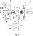
In
Des Weiteren umfasst die Antriebsanordnung
Das Anschlusselement
Ein Rotor
Die erste elektrische Rotationsmaschine
One
The first electric
Eine Trennkupplung
Die zweite Welle
Die zweite Welle
Die Zwischenwelle
Eine Radantriebswelle
The
The
A
Ein von der Verbrennungskraftmaschine
Ein vom Rotor
Ein vom Rotor
Die Antriebsanordnung
One from the
The
Die
the
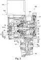
In
Die erste Welle
Die zweite Welle
Weiterhin ist ein die Statoren
Außerdem sind die Zwischenwelle
The
Furthermore one is the stators
Also are the
Die zentrale Lagereinheit
Des Weiteren ist eine Leistungselektronik
Die zweite Welle
Eine Außenverzahnung
The
An
Die Trennkupplung
Radial außerhalb der zentralen Lagereinheit
Radially outside the
Weiterhin ist eine Sicherungsschraube
In
Der Ausschnitt zeigt eine Antriebseinheit
Zu sehen ist in
The section shows a
Can be seen in
Alternativ zur Antriebseinheit
Unterschiedlich zur
Diese Stator-Einheit
Different from
This
Mit der erfindungsgemäßen Antriebseinheit sowie der Antriebsanordnung lässt sich in kostengünstiger Ausgestaltung sowie bauraumsparender Weise ein optimaler Betrieb gewährleisten.With the drive unit according to the invention and the drive arrangement, optimal operation can be ensured in a cost-effective configuration and in a manner that saves space.
BezugszeichenlisteList of reference symbols
- 11
- AntriebseinheitDrive unit
- 22
- Eingangsseite der AntriebseinheitInput side of the drive unit
- 33rd
- Ausgangsseite der AntriebseinheitOutput side of the drive unit
- 44th
- Anschlusselement der AntriebseinheitConnection element of the drive unit
- 55
- innenverzahntes Zahnrad des Anschlusselementsinternally toothed gear of the connection element
- 1010
- erste elektrische Rotationsmaschinefirst electric rotary machine
- 1111
- Rotor der ersten elektrischen RotationsmaschineRotor of the first electric rotary machine
- 1212th
- Stator der ersten elektrischen RotationsmaschineStator of the first electric rotating machine
- 2020th
- zweite elektrische Rotationsmaschinesecond rotary electric machine
- 2121
- Rotor der zweiten elektrischen RotationsmaschineRotor of the second rotary electric machine
- 2222nd
- Stator der zweiten elektrischen RotationsmaschineStator of the second rotating electric machine
- 3030th
- Rotorträger der zweiten elektrischen RotationsmaschineRotor arm of the second electric rotary machine
- 3131
- Stator-EinheitStator unit
- 3232
- gemeinsamer Stator-Trägercommon stator carrier
- 3333
- TrägerschraubeSupport screw
- 3434
- RotorlagesensorRotor position sensor
- 3535
- SicherungsschraubeLocking screw
- 4040
- erste Wellefirst wave
- 4141
- zweite Wellesecond wave
- 4242
- erster axialer Endbereich der ersten Wellefirst axial end region of the first shaft
- 4343
- zweiter axialer Endbereich der ersten Wellesecond axial end region of the first shaft
- 4444
- erster axialer Endbereich der zweiten Wellefirst axial end region of the second shaft
- 4545
- zweiter axialer Endbereich der zweiten Wellesecond axial end region of the second shaft
- 4646
- Außenverzahnung der ersten WelleExternal toothing of the first shaft
- 4747
- Außenverzahnung der zweiten WelleExternal teeth of the second shaft
- 5050
- TrennkupplungDisconnect clutch
- 5151
- Eingangsseite der TrennkupplungInput side of the disconnect clutch
- 5252
- Ausgangsseite der TrennkupplungOutput side of the separating clutch
- 5353
- BetätigungssystemActuation system
- 6060
- erstes Gehäusefirst housing
- 6161
- zweites Gehäusesecond housing
- 6262
- GehäuseelementHousing element
- 7070
- erste Übersetzungsstufefirst translation stage
- 7171
- zweite Übersetzungsstufesecond gear ratio
- 7272
- dritte Übersetzungsstufethird translation stage
- 8080
- DifferentialgetriebeDifferential gear
- 8181
- ZwischenwelleIntermediate shaft
- 8282
- erstes Zahnradfirst gear
- 8383
- zweites Zahnradsecond gear
- 8484
- Außenverzahnung der ZwischenwelleExternal teeth of the intermediate shaft
- 9090
- zentrale Lagereinheitcentral storage unit
- 9191
- NadellagerNeedle roller bearings
- 9292
- StützlagerSupport bearing
- 9393
- zweireihige Lagereinheitdouble row storage unit
- 100100
- AntriebsanordnungDrive arrangement
- 101101
- SchwingungsdämpferVibration damper
- 102102
- LeistungselektronikPower electronics
- 103103
- RadantriebswelleWheel drive shaft
- 104104
- PumpenaktorPump actuator
- 105105
- WärmetauscherHeat exchanger
- 110110
- VerbrennungskraftmaschineInternal combustion engine
- 111111
- Abtriebselement der VerbrennungskraftmaschineOutput element of the internal combustion engine
Claims (8)
Translated fromGermanPriority Applications (7)
| Application Number | Priority Date | Filing Date | Title |
|---|---|---|---|
| DE102019132941.8ADE102019132941B4 (en) | 2019-12-04 | 2019-12-04 | Drive unit and drive arrangement |
| CN202080084594.2ACN114761265B (en) | 2019-12-04 | 2020-10-21 | Drive units and drive components |
| PCT/DE2020/100907WO2021110194A1 (en) | 2019-12-04 | 2020-10-21 | Drive unit and drive assembly |
| EP20808292.5AEP4069538B1 (en) | 2019-12-04 | 2020-10-21 | Drive unit and drive assembly |
| US17/782,177US20230041635A1 (en) | 2019-12-04 | 2020-10-21 | Drive unit and drive assembly |
| KR1020227018014AKR102722037B1 (en) | 2019-12-04 | 2020-10-21 | Drive Unit and Drive Assembly |
| JP2022533652AJP7354449B2 (en) | 2019-12-04 | 2020-10-21 | Drives and drive assemblies |
Applications Claiming Priority (1)
| Application Number | Priority Date | Filing Date | Title |
|---|---|---|---|
| DE102019132941.8ADE102019132941B4 (en) | 2019-12-04 | 2019-12-04 | Drive unit and drive arrangement |
Publications (2)
| Publication Number | Publication Date |
|---|---|
| DE102019132941A1 DE102019132941A1 (en) | 2021-06-10 |
| DE102019132941B4true DE102019132941B4 (en) | 2021-09-30 |
Family
ID=73475840
Family Applications (1)
| Application Number | Title | Priority Date | Filing Date |
|---|---|---|---|
| DE102019132941.8AActiveDE102019132941B4 (en) | 2019-12-04 | 2019-12-04 | Drive unit and drive arrangement |
Country Status (7)
| Country | Link |
|---|---|
| US (1) | US20230041635A1 (en) |
| EP (1) | EP4069538B1 (en) |
| JP (1) | JP7354449B2 (en) |
| KR (1) | KR102722037B1 (en) |
| CN (1) | CN114761265B (en) |
| DE (1) | DE102019132941B4 (en) |
| WO (1) | WO2021110194A1 (en) |
Cited By (1)
| Publication number | Priority date | Publication date | Assignee | Title |
|---|---|---|---|---|
| US12441175B2 (en) | 2020-09-04 | 2025-10-14 | Schaeffler Technologies AG & Co. KG | Drive unit and drive assembly |
Families Citing this family (9)
| Publication number | Priority date | Publication date | Assignee | Title |
|---|---|---|---|---|
| DE102019132942B4 (en) | 2019-12-04 | 2024-07-25 | Schaeffler Technologies AG & Co. KG | Drive unit and drive arrangement |
| US20230039195A1 (en)* | 2020-01-14 | 2023-02-09 | Nidec Corporation | Motor unit and electric car |
| DE102020109781A1 (en) | 2020-04-08 | 2021-10-14 | Schaeffler Technologies AG & Co. KG | Hybrid vehicle drive train with two-electric machine transmission for serial drive and hybrid vehicle |
| DE202020005997U1 (en) | 2020-09-04 | 2024-01-24 | Schaeffler Technologies AG & Co. KG | Drive unit and drive arrangement |
| DE102020123116A1 (en) | 2020-09-04 | 2022-03-10 | Schaeffler Technologies AG & Co. KG | Drive unit and drive arrangement |
| US12179600B2 (en) | 2021-05-03 | 2024-12-31 | Schaeffler Technologies AG & Co. KG | Hybrid transmission, and drive train having a hybrid transmission |
| CN114198471B (en)* | 2021-12-24 | 2024-04-12 | 成都飞亚航空设备应用研究所有限公司 | Single-motor two-section driving rotary actuator |
| DE102022107665A1 (en) | 2022-03-31 | 2023-10-05 | Schaeffler Technologies AG & Co. KG | Stator unit, drive unit and drive arrangement |
| KR20230153086A (en)* | 2022-04-28 | 2023-11-06 | 현대자동차주식회사 | Hybrid power train for vhicle |
Citations (5)
| Publication number | Priority date | Publication date | Assignee | Title |
|---|---|---|---|---|
| DE10154147C1 (en) | 2001-11-03 | 2003-07-24 | Daimler Chrysler Ag | hybrid drive |
| WO2011054097A1 (en) | 2009-11-03 | 2011-05-12 | Tm4 Inc. | Hybrid vehicle transmission |
| US20160218584A1 (en) | 2015-01-28 | 2016-07-28 | Honda Motor Co., Ltd. | Integrated system |
| DE112015006071T5 (en) | 2015-01-28 | 2017-10-12 | Honda Motor Co., Ltd. | Hybrid vehicle drive system |
| WO2019101264A1 (en) | 2017-11-23 | 2019-05-31 | Schaeffler Technologies AG & Co. KG | Hybrid powertrain with two electric machines and an internal combustion engine |
Family Cites Families (25)
| Publication number | Priority date | Publication date | Assignee | Title |
|---|---|---|---|---|
| JP2001145209A (en)* | 1999-11-18 | 2001-05-25 | Denso Corp | Vehicle dynamoelectric machine |
| JP3641243B2 (en)* | 2002-02-26 | 2005-04-20 | 日産自動車株式会社 | Hybrid transmission |
| JP3857669B2 (en)* | 2002-09-04 | 2006-12-13 | 日産自動車株式会社 | Hybrid transmission |
| US6952061B2 (en)* | 2002-11-28 | 2005-10-04 | Honda Motor Co., Ltd | Motor drive unit |
| JP3641265B2 (en)* | 2002-12-04 | 2005-04-20 | 日産自動車株式会社 | Hybrid transmission |
| JP3700709B2 (en)* | 2003-04-03 | 2005-09-28 | 日産自動車株式会社 | Shift control device for hybrid transmission |
| JP3797354B2 (en)* | 2003-09-30 | 2006-07-19 | アイシン・エィ・ダブリュ株式会社 | Electric vehicle drive control device and electric vehicle drive control method |
| US7090613B2 (en)* | 2004-05-15 | 2006-08-15 | General Motors Corporation | Method of providing electric motor torque reserve in a hybrid electric vehicle |
| JP4179266B2 (en)* | 2004-11-08 | 2008-11-12 | 日産自動車株式会社 | Hybrid four-wheel drive system |
| JP4265570B2 (en)* | 2005-05-10 | 2009-05-20 | トヨタ自動車株式会社 | Power output device, automobile equipped with the same, drive device, and control method for power output device |
| DE102006041159B4 (en)* | 2006-09-01 | 2012-04-19 | Audi Ag | Hybrid drive device |
| JP4434194B2 (en)* | 2006-10-31 | 2010-03-17 | トヨタ自動車株式会社 | Control device for vehicle drive device |
| US8337352B2 (en)* | 2010-06-22 | 2012-12-25 | Oshkosh Corporation | Electromechanical variable transmission |
| WO2012114430A1 (en)* | 2011-02-21 | 2012-08-30 | スズキ株式会社 | Hybrid vehicle drive control device |
| US9033836B2 (en)* | 2011-10-08 | 2015-05-19 | Finemech Co., Ltd. | Drive device for hybrid electric vehicle |
| ITMO20120044A1 (en)* | 2012-02-23 | 2013-08-24 | Simone Casali | ELECTRIC MOTOR GROUP |
| KR101416420B1 (en)* | 2013-06-24 | 2014-07-09 | 현대자동차 주식회사 | Transmission system of hybrid electric vehicle |
| DE102014205886A1 (en)* | 2014-03-28 | 2015-10-01 | Siemens Aktiengesellschaft | Electric drive unit, in particular for a hybrid electric motor vehicle |
| KR101610089B1 (en)* | 2014-09-23 | 2016-04-07 | 현대자동차 주식회사 | Transmission system of hybrid electric vehicle |
| JP6344358B2 (en)* | 2015-10-05 | 2018-06-20 | トヨタ自動車株式会社 | Drive device for hybrid vehicle |
| US9638292B1 (en)* | 2015-10-27 | 2017-05-02 | Schaeffler Technologies AG & Co. KG | CVT differential |
| US10493978B2 (en)* | 2016-03-18 | 2019-12-03 | Gkn Automotive Ltd. | Electric drive |
| JP6819083B2 (en)* | 2016-06-13 | 2021-01-27 | 三菱自動車工業株式会社 | Transaxle device |
| KR102383223B1 (en)* | 2016-12-12 | 2022-04-05 | 현대자동차 주식회사 | Power transmission system of hybrid electric vehicle |
| KR20200067530A (en)* | 2018-12-04 | 2020-06-12 | 현대자동차주식회사 | Power transmission system of hybrid electric vehicle |
- 2019
- 2019-12-04DEDE102019132941.8Apatent/DE102019132941B4/enactiveActive
- 2020
- 2020-10-21CNCN202080084594.2Apatent/CN114761265B/enactiveActive
- 2020-10-21WOPCT/DE2020/100907patent/WO2021110194A1/ennot_activeCeased
- 2020-10-21JPJP2022533652Apatent/JP7354449B2/enactiveActive
- 2020-10-21KRKR1020227018014Apatent/KR102722037B1/enactiveActive
- 2020-10-21EPEP20808292.5Apatent/EP4069538B1/enactiveActive
- 2020-10-21USUS17/782,177patent/US20230041635A1/ennot_activeAbandoned
Patent Citations (5)
| Publication number | Priority date | Publication date | Assignee | Title |
|---|---|---|---|---|
| DE10154147C1 (en) | 2001-11-03 | 2003-07-24 | Daimler Chrysler Ag | hybrid drive |
| WO2011054097A1 (en) | 2009-11-03 | 2011-05-12 | Tm4 Inc. | Hybrid vehicle transmission |
| US20160218584A1 (en) | 2015-01-28 | 2016-07-28 | Honda Motor Co., Ltd. | Integrated system |
| DE112015006071T5 (en) | 2015-01-28 | 2017-10-12 | Honda Motor Co., Ltd. | Hybrid vehicle drive system |
| WO2019101264A1 (en) | 2017-11-23 | 2019-05-31 | Schaeffler Technologies AG & Co. KG | Hybrid powertrain with two electric machines and an internal combustion engine |
Cited By (1)
| Publication number | Priority date | Publication date | Assignee | Title |
|---|---|---|---|---|
| US12441175B2 (en) | 2020-09-04 | 2025-10-14 | Schaeffler Technologies AG & Co. KG | Drive unit and drive assembly |
Also Published As
| Publication number | Publication date |
|---|---|
| KR20220088491A (en) | 2022-06-27 |
| JP7354449B2 (en) | 2023-10-02 |
| EP4069538A1 (en) | 2022-10-12 |
| DE102019132941A1 (en) | 2021-06-10 |
| CN114761265A (en) | 2022-07-15 |
| US20230041635A1 (en) | 2023-02-09 |
| WO2021110194A1 (en) | 2021-06-10 |
| KR102722037B1 (en) | 2024-10-28 |
| JP2023505665A (en) | 2023-02-10 |
| EP4069538B1 (en) | 2024-12-11 |
| CN114761265B (en) | 2025-06-06 |
Similar Documents
| Publication | Publication Date | Title |
|---|---|---|
| DE102019132941B4 (en) | Drive unit and drive arrangement | |
| DE102009033962B4 (en) | Powertrain with motor, gear, planetary gear and electrical machine | |
| DE102019132942B4 (en) | Drive unit and drive arrangement | |
| EP3826872A2 (en) | Hybrid gear mechanism, hybrid drive assembly and method for operating a hybird drive assembly | |
| EP3807112B1 (en) | Drive unit for a powertrain of an electrically driveable motor vehicle, and drive assembly | |
| DE202019006038U1 (en) | Drive unit and drive arrangement | |
| EP3558737B1 (en) | Drive arrangement and motor vehicle | |
| EP4208361A1 (en) | Drive unit and drive assembly | |
| EP3810449B1 (en) | Drive unit for a drive train of an electrically driven motor vehicle and drive assembly | |
| WO2021190699A1 (en) | Drive unit and drive assembly | |
| DE102020109237A1 (en) | Hybrid drive system with multiple gear mechanism; as well as motor vehicle | |
| DE102021114919A1 (en) | Drive unit and drive arrangement | |
| DE102020109236A1 (en) | Hybrid drive system with multiple gear mechanism; as well as motor vehicle | |
| DE102019120145A1 (en) | Hybrid transmission arrangement with stationary air conditioning | |
| DE102016214404A1 (en) | Powertrain for a hybrid vehicle, as well as hybrid vehicle | |
| DE102020100604A1 (en) | Drive system for a hybrid motor vehicle, with two electrical machines and a longitudinally installed internal combustion engine; as well as motor vehicle | |
| DE102021114641A1 (en) | Drive unit and drive arrangement | |
| DE102021210740B3 (en) | Transmission for a vehicle and drive train with such a transmission | |
| DE202020005997U1 (en) | Drive unit and drive arrangement | |
| DE102023115644B4 (en) | drive unit and drive arrangement | |
| DE102019001516A1 (en) | Drive train for a motor vehicle, in particular for a motor vehicle | |
| DE102020100605A1 (en) | Drive system for a hybrid motor vehicle, with two electrical machines and a longitudinally installed internal combustion engine; as well as motor vehicle | |
| DE102019109269A1 (en) | Hybrid module and drive train for a motor vehicle | |
| DE102021117541A1 (en) | Drive train for a motor vehicle and motor vehicle | |
| DE202020005923U1 (en) | Hybrid drive system with multi-speed transmission; as well as motor vehicle |
Legal Events
| Date | Code | Title | Description |
|---|---|---|---|
| R012 | Request for examination validly filed | ||
| R016 | Response to examination communication | ||
| R018 | Grant decision by examination section/examining division | ||
| R020 | Patent grant now final |