DE102019129811A1 - Surgical instrument and optical obturator for a surgical instrument - Google Patents
Surgical instrument and optical obturator for a surgical instrumentDownload PDFInfo
- Publication number
- DE102019129811A1 DE102019129811A1DE102019129811.3ADE102019129811ADE102019129811A1DE 102019129811 A1DE102019129811 A1DE 102019129811A1DE 102019129811 ADE102019129811 ADE 102019129811ADE 102019129811 A1DE102019129811 A1DE 102019129811A1
- Authority
- DE
- Germany
- Prior art keywords
- obturator
- shaft
- surgical instrument
- optics
- optical
- Prior art date
- Legal status (The legal status is an assumption and is not a legal conclusion. Google has not performed a legal analysis and makes no representation as to the accuracy of the status listed.)
- Pending
Links
- 230000003287optical effectEffects0.000titleclaimsabstractdescription28
- 230000008878couplingEffects0.000description9
- 238000010168coupling processMethods0.000description9
- 238000005859coupling reactionMethods0.000description9
- 239000013307optical fiberSubstances0.000description4
- 230000003993interactionEffects0.000description3
- 238000003780insertionMethods0.000description2
- 230000037431insertionEffects0.000description2
- 239000000696magnetic materialSubstances0.000description2
- 238000011282treatmentMethods0.000description2
- 230000003213activating effectEffects0.000description1
- 238000010276constructionMethods0.000description1
- 239000000463materialSubstances0.000description1
- 229910052751metalInorganic materials0.000description1
- 238000012978minimally invasive surgical procedureMethods0.000description1
- 229910001172neodymium magnetInorganic materials0.000description1
- 238000001356surgical procedureMethods0.000description1
- 210000003932urinary bladderAnatomy0.000description1
Images

Classifications
- A—HUMAN NECESSITIES
- A61—MEDICAL OR VETERINARY SCIENCE; HYGIENE
- A61B—DIAGNOSIS; SURGERY; IDENTIFICATION
- A61B17/00—Surgical instruments, devices or methods
- A61B17/34—Trocars; Puncturing needles
- A61B17/3417—Details of tips or shafts, e.g. grooves, expandable, bendable; Multiple coaxial sliding cannulas, e.g. for dilating
- A—HUMAN NECESSITIES
- A61—MEDICAL OR VETERINARY SCIENCE; HYGIENE
- A61B—DIAGNOSIS; SURGERY; IDENTIFICATION
- A61B1/00—Instruments for performing medical examinations of the interior of cavities or tubes of the body by visual or photographical inspection, e.g. endoscopes; Illuminating arrangements therefor
- A61B1/00064—Constructional details of the endoscope body
- A61B1/00071—Insertion part of the endoscope body
- A61B1/0008—Insertion part of the endoscope body characterised by distal tip features
- A61B1/00096—Optical elements
- A—HUMAN NECESSITIES
- A61—MEDICAL OR VETERINARY SCIENCE; HYGIENE
- A61B—DIAGNOSIS; SURGERY; IDENTIFICATION
- A61B1/00—Instruments for performing medical examinations of the interior of cavities or tubes of the body by visual or photographical inspection, e.g. endoscopes; Illuminating arrangements therefor
- A61B1/00112—Connection or coupling means
- A61B1/00121—Connectors, fasteners and adapters, e.g. on the endoscope handle
- A—HUMAN NECESSITIES
- A61—MEDICAL OR VETERINARY SCIENCE; HYGIENE
- A61B—DIAGNOSIS; SURGERY; IDENTIFICATION
- A61B1/00—Instruments for performing medical examinations of the interior of cavities or tubes of the body by visual or photographical inspection, e.g. endoscopes; Illuminating arrangements therefor
- A61B1/00131—Accessories for endoscopes
- A61B1/00135—Oversleeves mounted on the endoscope prior to insertion
- A—HUMAN NECESSITIES
- A61—MEDICAL OR VETERINARY SCIENCE; HYGIENE
- A61B—DIAGNOSIS; SURGERY; IDENTIFICATION
- A61B1/00—Instruments for performing medical examinations of the interior of cavities or tubes of the body by visual or photographical inspection, e.g. endoscopes; Illuminating arrangements therefor
- A61B1/00147—Holding or positioning arrangements
- A61B1/00154—Holding or positioning arrangements using guiding arrangements for insertion
- A—HUMAN NECESSITIES
- A61—MEDICAL OR VETERINARY SCIENCE; HYGIENE
- A61B—DIAGNOSIS; SURGERY; IDENTIFICATION
- A61B17/00—Surgical instruments, devices or methods
- A61B2017/00831—Material properties
- A61B2017/00876—Material properties magnetic
- A—HUMAN NECESSITIES
- A61—MEDICAL OR VETERINARY SCIENCE; HYGIENE
- A61B—DIAGNOSIS; SURGERY; IDENTIFICATION
- A61B17/00—Surgical instruments, devices or methods
- A61B2017/00831—Material properties
- A61B2017/00902—Material properties transparent or translucent
- A61B2017/00907—Material properties transparent or translucent for light
- A—HUMAN NECESSITIES
- A61—MEDICAL OR VETERINARY SCIENCE; HYGIENE
- A61B—DIAGNOSIS; SURGERY; IDENTIFICATION
- A61B90/00—Instruments, implements or accessories specially adapted for surgery or diagnosis and not covered by any of the groups A61B1/00 - A61B50/00, e.g. for luxation treatment or for protecting wound edges
- A61B90/36—Image-producing devices or illumination devices not otherwise provided for
- A61B90/361—Image-producing devices, e.g. surgical cameras
- A61B2090/3614—Image-producing devices, e.g. surgical cameras using optical fibre
Landscapes
- Health & Medical Sciences (AREA)
- Life Sciences & Earth Sciences (AREA)
- Surgery (AREA)
- Nuclear Medicine, Radiotherapy & Molecular Imaging (AREA)
- Molecular Biology (AREA)
- Veterinary Medicine (AREA)
- Pathology (AREA)
- Public Health (AREA)
- General Health & Medical Sciences (AREA)
- Engineering & Computer Science (AREA)
- Biomedical Technology (AREA)
- Heart & Thoracic Surgery (AREA)
- Medical Informatics (AREA)
- Animal Behavior & Ethology (AREA)
- Physics & Mathematics (AREA)
- Biophysics (AREA)
- Radiology & Medical Imaging (AREA)
- Optics & Photonics (AREA)
- Endoscopes (AREA)
Abstract
Translated fromGermanDescription
Translated fromGermanDie Erfindung betrifft einen optischen Obturator für ein chirurgisches Instrument gemäß dem Oberbegriff des Anspruchs 1. Des Weiteren betrifft die Erfindung ein chirurgisches Instrument mit einem optischen Obturator gemäß dem Anspruch 10.The invention relates to an optical obturator for a surgical instrument according to the preamble of claim 1. Furthermore, the invention relates to a surgical instrument with an optical obturator according to
Chirurgische Instrumente, wie beispielsweise Endoskope, Zystoskope, Resektoskope oder dergleichen dienen zur Verwendung bei minimal invasiven chirurgischen Verfahren. Auch Trokare, die zur Einrichtung eines Zugangs für endoskopische Instrumente zur primären und sekundären Insertion dienen, sind von der vorliegenden Beschreibung umfasst. Die vorgenannten chirurgischen Instrumente weisen einen länglichen rohrförmigen Schaft auf. Dieser Schaft wird zur Untersuchung bzw. zur Behandlung von Patienten in einen Körper eingeführt. In dem Schaft bzw. einem Schaftrohr sind für die Untersuchung bzw. die Behandlung verschiedene medizinische Instrumente anordbar. So kann beispielsweise in einem Endoskop eine Optik zur Bilderzeugung oder zur Bildaufnahme im Inneren des menschlichen Körpers angeordnet sein. Bei Resektoskopen für Hochfrequenzchirurgie kann in ein Schaftrohr eine mit hochfrequentem Wechselstrom beaufschlagbare Elektrode an einem Elektrodenträger eingeführt werden. Gleichermaßen können über Zystoskope Werkzeuge in das Körperinnere eines Patienten eingeführt werden, um beispielsweise Behandlungen an der Harnblase durchzuführen.Surgical instruments such as endoscopes, cystoscopes, resectoscopes or the like are used in minimally invasive surgical procedures. Trocars, which are used to establish access for endoscopic instruments for primary and secondary insertion, are also covered by the present description. The aforementioned surgical instruments have an elongated tubular shaft. This shaft is inserted into a body for examining or treating patients. Various medical instruments can be arranged in the shaft or a shaft tube for the examination or treatment. For example, an optical system for generating or recording images can be arranged inside the human body in an endoscope. In resectoscopes for high-frequency surgery, an electrode on an electrode carrier that can be charged with high-frequency alternating current can be inserted into a shaft tube. Likewise, tools can be inserted into the interior of a patient via cystoscopes, for example in order to carry out treatments on the urinary bladder.
Um beim Einführen der Instrumente in den zu untersuchenden bzw. zu behandelnden Körperbereich kein Gewebe bzw. keine Körperteile unnötig zu verletzen, kann während des Einführens der Instrumente anstelle der vorgenannten Werkzeuge ein Obturator durch den Schaft des Instrumentes geführt werden. Der Obturator weist zumeist einen stabförmigen Schaft auf, dessen distales Ende flach bzw. abgerundet ausgebildet ist. Nachdem das Instrument mit dem Obturator in die richtige Position gebracht wurde, wird der Obturator durch ein entsprechendes chirurgisches Werkzeug ausgetauscht.In order not to unnecessarily injure any tissue or body parts when inserting the instruments into the body area to be examined or treated, an obturator can be passed through the shaft of the instrument instead of the aforementioned tools during the insertion of the instruments. The obturator mostly has a rod-shaped shaft, the distal end of which is flat or rounded. After the instrument has been brought into the correct position with the obturator, the obturator is exchanged for a suitable surgical tool.
Neben den Standart-Obturatoren sind außerdem optische Obturatoren bekannt, die zusätzlich eine Optik aufweisen. Durch diese Optik, bei der es sich um eine Lichtleitfaser oder eine Vielzahl von Stablinsen handeln kann, wird einem Operateur Einsicht in das Körperinnere gewährt. Dabei wird die teleskopartige Optik durch den rohrartigen Obturatort geführt, sodass der Operateur den distalen Endbereich des Instrumentes „auf Sicht“ positionieren kann.In addition to the standard obturators, optical obturators are also known which additionally have an optical system. This optic, which can be an optical fiber or a large number of rod lenses, allows a surgeon to see the inside of the body. The telescope-like optics are guided through the tubular obturator so that the surgeon can position the distal end area of the instrument “on sight”.
Durch die Konstruktion von längeren Instrumenten ist es teilweise notwendig geworden, auch die Schaftprofile im Durchmesser zu ändern bzw. zu reduzieren. Das hat zur Folge, dass auch der Innenraum bzw. Arbeitskanal des Schaftes für die Werkzeuge bzw. den Obturator reduziert ist. Für einen klassischen optischen Obturator, in dem die Optik in dem Obturator anzuordnen ist, verbleibt somit in dem Innenraum kein Platz mehr für die Optik. Die Lösung dieser Problematik bestand darin, den Obturator bzw. einen Schaft des Obturators und die Optik bzw. das Teleskop nebeneinanderliegend in den Instrumentenschaft einzuführen. Allerdings ist damit kein fester Reibschluss und auch kein Formschluss zwischen dem Obturator und der Optik zu erreichen. Das hat zur Folge, dass die distalen Endbereiche der Optik und des Obturators beim Einführen nicht mehr bündig zueinander liegen und nur umständlich in den Schaft einzuführen sind. Die Bündigkeit der Optik und des Obturators sind jedoch wesentlich für eine exakte und verlässliche Positionierung des Instrumentes.Due to the construction of longer instruments, it has sometimes become necessary to change or reduce the diameter of the shaft profile. As a result, the interior space or working channel of the shaft for the tools or the obturator is also reduced. For a classic optical obturator in which the optics are to be arranged in the obturator, there is no longer any space left in the interior for the optics. The solution to this problem was to introduce the obturator or a shaft of the obturator and the optics or the telescope into the instrument shaft next to one another. However, no firm frictional connection and also no form connection between the obturator and the optics can be achieved in this way. As a result, the distal end areas of the optics and the obturator are no longer flush with one another when they are inserted and can only be inserted into the shaft with difficulty. However, the flush alignment of the optics and the obturator are essential for an exact and reliable positioning of the instrument.
Davon ausgehend besteht die Aufgabe der vorliegenden Erfindung darin, einen optischen Obturator zu schaffen, mit dem sich ein chirurgisches Instrument auf eine präzise sowie verlässliche Art und Weise positionieren lässt.On this basis, the object of the present invention is to create an optical obturator with which a surgical instrument can be positioned in a precise and reliable manner.
Ein optischer Obturator zur Lösung dieser Aufgabe weist die Merkmale des Anspruchs 1 auf. Demnach ist es vorgesehen, dass die Optik mit dem Obturator bzw. einem Schaft des Obturators magnetisch koppelbar ist. Durch diese magnetische Kopplung zwischen der Optik und dem Obturator bzw. dem Schaft wird eine definierte Verbinduna zwischen den beiden Teilen hergestellt und ein Gegeneinanderverschieben unterbunden. Dadurch, dass der Obturator mit der Optik magnetisch verbindbar ist, lassen sich die distalen Endbereich zueinander ausrichten und in diesem ausgerichteten, gekoppelten Zustand in den Schaft des chirurgischen Instrumentes einführen, und zwar ohne, dass sich dabei die relative Anordnung verändert. Mittels dieser magnetischen Kopplung der Optik und des Obturators lässt sich somit eine genaue und verlässliche Positionierung des chirurgischen Instrumentes realisieren.An optical obturator for solving this problem has the features of claim 1. Accordingly, it is provided that the optics can be magnetically coupled to the obturator or a shaft of the obturator. This magnetic coupling between the optics and the obturator or the shaft creates a defined connection between the two parts and prevents them from moving in relation to one another. Because the obturator can be magnetically connected to the optics, the distal end regions can be aligned with one another and, in this aligned, coupled state, inserted into the shaft of the surgical instrument without the relative arrangement changing. By means of this magnetic coupling of the optics and the obturator, precise and reliable positioning of the surgical instrument can be achieved.
Insbesondere kann es die vorliegende Erfindung weiter vorsehen, dass distale Endbereiche der Optik und des Obturators magnetisch miteinander gekoppelt sind. Durch die Kopplung der Endbereiche kann sichergestellt werden, dass die größte Verbindungskraft zwischen den beiden genannten Gegenständen genau dort herrscht, wo eine besonders genaue relative Ausrichtung notwendig ist. Insbesondere die exakte Ausrichtung der distalen Endbereiche zueinander ist für eine genaue Positionierung des Instrumentes entscheidend. Durch die Kopplung der beiden Endbereiche kann außerdem erreicht werden, dass die Mittel zur magnetischen Verbindung reduziert werden auf einen einzigen Bereich, nämlich den distalen Endbereich. Dadurch lassen sich insbesondere Kosten, aber auch Platz bzw. Gewicht einsparen.In particular, the present invention can further provide that distal end regions of the optics and of the obturator are magnetically coupled to one another. By coupling the end areas, it can be ensured that the greatest connecting force between the two objects mentioned is present exactly where a particularly precise relative alignment is necessary. In particular, the exact alignment of the distal end areas to one another is crucial for precise positioning of the instrument. By coupling the two end areas, it can also be achieved that the means for magnetic connection are reduced to a single area, namely the distal end area. This saves costs in particular, but also space and weight.
Vorzugsweise sieht es die Erfindung weiter vor, dass der distale Endbereich des Obturators bzw. des Obturatorschaftes mindestens einen Magneten, vorzugsweise einen Permanentmagneten, insbesondere einen Neodym-Magneten, oder einen Elektromagneten aufweist. Durch die Verwendung eines Magneten bzw. eines Permanentmagneten lassen sich die distalen Endbereiche besonders genau und verlässlich miteinander koppeln. Durch entsprechende Verbindungen bzw. Strukturen von magnetischem Material lässt sich auf kleinstem Raum eine hohe magnetische Feldliniendichte erzielen, sodass das notwendige Volumen für die Anordnung eines Permanentmagneten sehr klein sein kann. Diese Möglichkeit der Miniaturisierung des mindestens einen Magneten steht im Einklang mit der Bestrebung, die in diesem Zusammenhang verwendeten Geräte bzw. Werkzeuge zu verkleinern. Die Verwendung eines Elektromagneten hätte den Vorteil, dass die Optik bzw. das Teleskop und der Obturator in dem Schaft des chirurgischen Instrumentes ausrichtbar sind und durch Aktivierung des Elektromagneten ihre relative Positionierung fixierbar ist.The invention preferably further provides that the distal end region of the obturator or of the obturator shaft has at least one magnet, preferably a permanent magnet, in particular a neodymium magnet, or an electromagnet. By using a magnet or a permanent magnet, the distal end regions can be coupled to one another particularly precisely and reliably. Appropriate connections or structures of magnetic material allow a high density of magnetic field lines to be achieved in a very small space, so that the volume required for the arrangement of a permanent magnet can be very small. This possibility of miniaturizing the at least one magnet is consistent with efforts to reduce the size of the devices or tools used in this context. The use of an electromagnet would have the advantage that the optics or the telescope and the obturator can be aligned in the shaft of the surgical instrument and their relative positioning can be fixed by activating the electromagnet.
Ein weiteres Merkmal der vorliegenden Erfindung kann es vorsehen, dass der distale Endbereich der Optik wenigstens teilweise magnetisch ist. Dazu kann der distale Endbereich beispielsweise einen metallischen Ring oder ein sonstiges Element aufweisen, welches magnetisch ist. So ist es beispielsweise denkbar, dass eine Lichtleitfaser wenigstens an einem distalen Endbereich ein metallisches Element aufweist, um mit dem Magneten am distalen Endbereich des Obturators eine magnetische Wechselwirkung einzugehen.Another feature of the present invention can provide that the distal end region of the optics is at least partially magnetic. For this purpose, the distal end area can have, for example, a metallic ring or some other element which is magnetic. For example, it is conceivable that an optical fiber has a metallic element at least at one distal end area in order to enter into a magnetic interaction with the magnet at the distal end area of the obturator.
Ein weiteres vorteilhaftes Ausführungsbeispiel der vorliegenden Erfindung kann es vorsehen, dass der distalen Endbereich des Obturators zur Aufnahme der Optik schalenartig, insbesondere halbschalenartig, ausgebildet ist. Durch diese halbschalenartige Form des Obturators kann die Optik bzw. das Teleskop besonders positionssicher aufgenommen werden. Durch die magnetische Wechselwirkung zwischen den beiden Gegenständen fügt sich die Optik beim Zusammenfügen der beiden Gegenstände nahezu selbstständig in die bevorzugte Position. Durch diese halbschalenartige Ausgestaltung des Obturators gestaltet sich der optische Obturator besonders platzsparend, womit er sich auch in besonders dünnen Instrumenten einsetzen lässt.A further advantageous exemplary embodiment of the present invention can provide that the distal end region of the obturator for receiving the optics is designed in a shell-like manner, in particular half-shell-like. This half-shell-like shape of the obturator allows the optics or the telescope to be received in a particularly secure manner. Due to the magnetic interaction between the two objects, the optics automatically move into the preferred position when the two objects are joined together. As a result of this half-shell-like configuration of the obturator, the optical obturator is designed to be particularly space-saving, so that it can also be used in particularly thin instruments.
Ein weiteres Ausführungsbeispiel kann es vorsehen, dass ein Krümmungsradius des schalenartigen Endbereichs des Obturators mit einem Krümmungsradius der Optik korrespondiert. Durch diese Korrespondenz der Krümmungsradien umfasst der Obturator die Optik wenigstens teilweise. Dabei kann sich die schalenartige Ausbildung entweder auf den distalen Bereich des Obturators begrenzen oder über wenigstens nahezu die gesamte Länge des Obturators erstrecken.Another exemplary embodiment can provide that a radius of curvature of the shell-like end region of the obturator corresponds to a radius of curvature of the optics. As a result of this correspondence of the radii of curvature, the obturator at least partially encloses the optics. The shell-like design can either be limited to the distal area of the obturator or extend over at least almost the entire length of the obturator.
Weiter kann es vorgesehen sein, dass der Magnet zur Erzeugung der magnetischen Wechselwirkung in eine Bohrung für den Schaft des Obturators bzw. für einen Führungsstab in dem Endbereich des Obturators einsetzbar ist. Dabei ist insbesondere darauf zu achten, dass das den Magneten umgebende Material die magnetischen Feldlinien des Magneten nicht zu stark abschwächt.It can further be provided that the magnet for generating the magnetic interaction can be inserted into a bore for the shaft of the obturator or for a guide rod in the end region of the obturator. It is particularly important to ensure that the material surrounding the magnet does not weaken the magnetic field lines of the magnet too much.
Ein weiteres Ausführungsbeispiel der Erfindung kann es vorsehen, dass der Obturator rohrartig ausgebildet ist und im Inneren des Obturators die Optik aufnehmbar bzw. einführbar ist. In diesem Fall ist der mindestens eine Magnet in einer ringartigen Wandung des Obturators angeordnet. Dabei kann es sich insbesondere um einen Ringmagneten handeln.Another exemplary embodiment of the invention can provide that the obturator is tubular and the optics can be received or inserted in the interior of the obturator. In this case, the at least one magnet is arranged in an annular wall of the obturator. This can in particular be a ring magnet.
Ein chirurgisches Instrument zur Lösung der eingangs genannten Aufgabe weist gemäß dem Anspruch 10 einen optischen Obturator gemäß mindestens einem der Ansprüche 1 bis 9 auf.According to
Ein bevorzugtes Ausführungsbeispiel der Erfindung wird nachfolgend anhand der Zeichnung näher erläutert. In dieser zeigen:
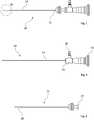
1 eine schematische Ansicht eines optischen Obturators,2 eine schematische Ansicht einer Optik,3 eine schematische Ansicht eines Obturators, und4 eine Ausschnittsvergrößerung eines in1 dargestellten distalen Bereichs des optischen Obturators.
1 a schematic view of an optical obturator,2 a schematic view of an optic,3 a schematic view of an obturator, and4th an enlarged section of an in1 shown distal area of the optical obturator.
In der
Der Schaft
Der in der
Der in der
Für eine besonders platzsparende Ausgestaltung des optischen Obturators
BezugszeichenlisteList of reference symbols
- 1010
- optischer Obturatoroptical obturator
- 1111
- Schaftshaft
- 1212th
- Optikoptics
- 1313th
- HauptkörperMain body
- 1414th
- Schaftshaft
- 1515th
- Anschlussconnection
- 1616
- Okulareyepiece
- 1717th
- KopplungskörperCoupling body
- 1818th
- ObturatorspitzeObturator tip
- 1919th
- Hohlraumcavity
- 2020th
- Magnetmagnet
Claims (10)
Translated fromGermanPriority Applications (1)
| Application Number | Priority Date | Filing Date | Title |
|---|---|---|---|
| DE102019129811.3ADE102019129811A1 (en) | 2019-11-05 | 2019-11-05 | Surgical instrument and optical obturator for a surgical instrument |
Applications Claiming Priority (1)
| Application Number | Priority Date | Filing Date | Title |
|---|---|---|---|
| DE102019129811.3ADE102019129811A1 (en) | 2019-11-05 | 2019-11-05 | Surgical instrument and optical obturator for a surgical instrument |
Publications (1)
| Publication Number | Publication Date |
|---|---|
| DE102019129811A1true DE102019129811A1 (en) | 2021-05-06 |
Family
ID=75485662
Family Applications (1)
| Application Number | Title | Priority Date | Filing Date |
|---|---|---|---|
| DE102019129811.3APendingDE102019129811A1 (en) | 2019-11-05 | 2019-11-05 | Surgical instrument and optical obturator for a surgical instrument |
Country Status (1)
| Country | Link |
|---|---|
| DE (1) | DE102019129811A1 (en) |
Citations (4)
| Publication number | Priority date | Publication date | Assignee | Title |
|---|---|---|---|---|
| US20090048591A1 (en)* | 2007-05-21 | 2009-02-19 | Estech, Inc. | Cardiac ablation systems and methods |
| US20100016664A1 (en)* | 2006-12-20 | 2010-01-21 | Tyco Healthcare Group Lp | Surgical visual obturator |
| DE102011056705A1 (en)* | 2011-12-20 | 2013-06-20 | Aesculap Ag | Medical obturator and trocar |
| US20190150966A1 (en)* | 2007-12-20 | 2019-05-23 | Atricure, Inc. | Magnetic introducer systems and methods |
- 2019
- 2019-11-05DEDE102019129811.3Apatent/DE102019129811A1/enactivePending
Patent Citations (4)
| Publication number | Priority date | Publication date | Assignee | Title |
|---|---|---|---|---|
| US20100016664A1 (en)* | 2006-12-20 | 2010-01-21 | Tyco Healthcare Group Lp | Surgical visual obturator |
| US20090048591A1 (en)* | 2007-05-21 | 2009-02-19 | Estech, Inc. | Cardiac ablation systems and methods |
| US20190150966A1 (en)* | 2007-12-20 | 2019-05-23 | Atricure, Inc. | Magnetic introducer systems and methods |
| DE102011056705A1 (en)* | 2011-12-20 | 2013-06-20 | Aesculap Ag | Medical obturator and trocar |
Similar Documents
| Publication | Publication Date | Title |
|---|---|---|
| DE19827360C2 (en) | Medical instrument for endoscopic removal of the saphenous vein | |
| EP1152684B1 (en) | Endoscope | |
| DE3881717T2 (en) | Endoscope. | |
| DE102006022827B4 (en) | endoscope | |
| EP2229871B1 (en) | Medical instrument, in particular hysteroscope | |
| WO2011079910A2 (en) | Endoscope, in particular for minimally invasive surgery on the spinal column | |
| EP1523932A1 (en) | Endoscope | |
| DE102014118003A1 (en) | Endoscopic instrument and endoscopic instrument system | |
| EP0601427A2 (en) | Endoscopic instrument | |
| DE3917663C2 (en) | ||
| EP3851019A1 (en) | Plug valve for an endoscope | |
| DE3936811A1 (en) | Endoscope for removal of gall stones - has dilator formed from several telescopic tubes | |
| WO2010105649A1 (en) | Tubular shaft of a surgical instrument and use of the same | |
| DE2222979A1 (en) | MEDICAL DEVICE | |
| DE102018114448A1 (en) | Resectoscope with flush-mounted irrigation tube | |
| DE102009060921A1 (en) | Puncture needle system | |
| DE202013103110U1 (en) | Medical instrument | |
| DE102019129811A1 (en) | Surgical instrument and optical obturator for a surgical instrument | |
| DE102012203908B3 (en) | Instrument system for minimally invasive surgery in the single-port technique | |
| EP3727125B1 (en) | Endoscope | |
| DE102022105184A1 (en) | Obturator for a surgical instrument | |
| DE10241946A1 (en) | Apparatus for minimally invasive surgical removal of foreign bodies having a tube with a lumen open at the distal end | |
| DE102021132986A1 (en) | Surgical handpiece and shaft for a surgical handpiece | |
| DE202017101684U1 (en) | Adapter for performing a percutaneous nephrolithotomy | |
| DE212017000295U1 (en) | Fiber optic tool and associated replaceable attachment (variants) |
Legal Events
| Date | Code | Title | Description |
|---|---|---|---|
| R012 | Request for examination validly filed | ||
| R016 | Response to examination communication |