DE102019122354A1 - Intramedullary nail for distraction of a long bone - Google Patents
Intramedullary nail for distraction of a long boneDownload PDFInfo
- Publication number
- DE102019122354A1 DE102019122354A1DE102019122354.7ADE102019122354ADE102019122354A1DE 102019122354 A1DE102019122354 A1DE 102019122354A1DE 102019122354 ADE102019122354 ADE 102019122354ADE 102019122354 A1DE102019122354 A1DE 102019122354A1
- Authority
- DE
- Germany
- Prior art keywords
- coil
- tube
- intramedullary nail
- locking opening
- area
- Prior art date
- Legal status (The legal status is an assumption and is not a legal conclusion. Google has not performed a legal analysis and makes no representation as to the accuracy of the status listed.)
- Pending
Links
Images
Classifications
- A—HUMAN NECESSITIES
- A61—MEDICAL OR VETERINARY SCIENCE; HYGIENE
- A61B—DIAGNOSIS; SURGERY; IDENTIFICATION
- A61B17/00—Surgical instruments, devices or methods
- A61B17/56—Surgical instruments or methods for treatment of bones or joints; Devices specially adapted therefor
- A61B17/58—Surgical instruments or methods for treatment of bones or joints; Devices specially adapted therefor for osteosynthesis, e.g. bone plates, screws or setting implements
- A61B17/68—Internal fixation devices, including fasteners and spinal fixators, even if a part thereof projects from the skin
- A61B17/72—Intramedullary devices, e.g. pins or nails
- A61B17/7216—Intramedullary devices, e.g. pins or nails for bone lengthening or compression
- A—HUMAN NECESSITIES
- A61—MEDICAL OR VETERINARY SCIENCE; HYGIENE
- A61B—DIAGNOSIS; SURGERY; IDENTIFICATION
- A61B17/00—Surgical instruments, devices or methods
- A61B17/56—Surgical instruments or methods for treatment of bones or joints; Devices specially adapted therefor
- A61B17/58—Surgical instruments or methods for treatment of bones or joints; Devices specially adapted therefor for osteosynthesis, e.g. bone plates, screws or setting implements
- A61B17/68—Internal fixation devices, including fasteners and spinal fixators, even if a part thereof projects from the skin
- A61B17/72—Intramedullary devices, e.g. pins or nails
- A61B17/7233—Intramedullary devices, e.g. pins or nails with special means of locking the nail to the bone
- A—HUMAN NECESSITIES
- A61—MEDICAL OR VETERINARY SCIENCE; HYGIENE
- A61B—DIAGNOSIS; SURGERY; IDENTIFICATION
- A61B17/00—Surgical instruments, devices or methods
- A61B2017/00367—Details of actuation of instruments, e.g. relations between pushing buttons, or the like, and activation of the tool, working tip, or the like
- A61B2017/00411—Details of actuation of instruments, e.g. relations between pushing buttons, or the like, and activation of the tool, working tip, or the like actuated by application of energy from an energy source outside the body
Landscapes
- Health & Medical Sciences (AREA)
- Orthopedic Medicine & Surgery (AREA)
- Surgery (AREA)
- Life Sciences & Earth Sciences (AREA)
- Heart & Thoracic Surgery (AREA)
- Nuclear Medicine, Radiotherapy & Molecular Imaging (AREA)
- Engineering & Computer Science (AREA)
- Biomedical Technology (AREA)
- Neurology (AREA)
- Medical Informatics (AREA)
- Molecular Biology (AREA)
- Animal Behavior & Ethology (AREA)
- General Health & Medical Sciences (AREA)
- Public Health (AREA)
- Veterinary Medicine (AREA)
- Surgical Instruments (AREA)
Abstract
Translated fromGermanDescription
Translated fromGermanGebiet der ErfindungField of invention
Die Erfindung betrifft einen Marknagel für eine Distraktion eines Röhrenknochens.The invention relates to an intramedullary nail for distraction of a long bone.
Stand der TechnikState of the art
Aus dem Stand der Technik sind Marknägel bekannt, welche eine Distraktion von langen Röhrenknochen ermöglichen. Zwei Knochenfragmente, ein erstes Knochenfragment und ein zweites Knochenfragment, werden relativ zueinander mittels eines Marknagels verschoben. An der Kontaktstelle zwischen den beiden Knochenfragmenten soll Knochen nachwachsen. Dies wird erreicht, indem eine Vorschubgeschwindigkeit eines Antriebs des Marknagels zur Distraktion ausreichend klein gewählt wird. Es ist bekannt, einen Marknagel transkutan mit Energie für den Antrieb zu versorgen. Beispielsweise sind aus der
Allerdings haben bisher bekannte Lösungen aus dem Stand der Technik Restriktionen in Bezug auf die Energieübertragungsleistung oder die Effizienz der Energieübertragung, benötigen mehr Raum oder erfordern das Verbinden einer außerhalb des Marknagels angeordneten Empfangsantenne mit dem Marknagel.However, previously known solutions from the prior art have restrictions with regard to the energy transmission capacity or the efficiency of the energy transmission, require more space or require a receiving antenna arranged outside the intramedullary nail to be connected to the intramedullary nail.
Offenbarung der ErfindungDisclosure of the invention
Aufgabe der Erfindung ist es, einen gegenüber dem Stand der Technik verbesserten Marknagel anzugeben. Insbesondere sollte ein Marknagel eine hohe Energieübertragungsleistung ermöglichen, eine hohe Effizienz der Energieübertragung aufweisen, wenig Raum im Knochen beanspruchen oder gelenksnah implantiert werden können. Weiterhin sind Marknägel wünschenswert, welche einen möglichst geringen Operationsaufwand benötigen oder eine zuverlässige Fixierung in den Knochenfragmenten ermöglichen.The object of the invention is to provide an intramedullary nail that is improved compared to the prior art. In particular, an intramedullary nail should enable a high energy transmission capacity, exhibit high energy transmission efficiency, take up little space in the bone or be able to be implanted close to the joint. Furthermore, intramedullary nails are desirable which require as little surgical effort as possible or enable reliable fixation in the bone fragments.
Gemäß einem Aspekt der Erfindung ist ein Marknagel für eine Distraktion eines Röhrenknochens mit einem sich in einer axialen Richtung des Marknagels erstreckenden ersten Rohr, einem sich in einer axialen Richtung des Marknagels erstreckenden zweiten Rohr, welches axial ineinander verschiebbar mit dem ersten Rohr verbunden ist, einer ersten Verriegelungsöffnung in einem dem zweiten Rohr abgewandten Endbereich des ersten Rohres, einer Spule, welche in einem Spulenbereich des ersten Rohres zwischen der ersten Verriegelungsöffnung und dem zweiten Rohr angeordnet ist.According to one aspect of the invention, an intramedullary nail for distraction of a long bone with a first tube extending in an axial direction of the intramedullary nail, a second tube extending in an axial direction of the intramedullary nail, which is connected to the first tube so as to be axially displaceable into one another, is a first locking opening in an end region of the first tube facing away from the second tube, a coil which is arranged in a coil region of the first tube between the first locking opening and the second tube.
Ein weiterer Aspekt der Erfindung betrifft ein Verfahren zum Übertragen von Energie von einer Primärspule zu einer Spule eines Marknagels in einer der hierin beschriebenen typischen Ausführungsformen, mit Bestromen der Primärspule, und Empfangen zumindest eines Teils der durch das Bestromen der Primärspule ausgesendeten elektromagnetischen Energie durch die Spule des Marknagels.Another aspect of the invention relates to a method for transmitting energy from a primary coil to a coil of an intramedullary nail in one of the typical embodiments described herein, with energizing the primary coil, and receiving at least part of the electromagnetic energy emitted by energizing the primary coil by the coil of the intramedullary nail.
Beispielhafte Marknägel eignen sich insbesondere zur Behandlung von Frakturen oder anderen Schädigungen von langen Röhrenknochen, wobei andere Schädigungen beispielsweise Knochenverluste aufgrund von Tumoren oder Gewalteinwirkung sein können. Knochen, welche mit typischen Marknägeln behandelt werden können, sind Oberschenkelknochen (Femur) und Schienenbein (Tibia), es können jedoch auch Oberarmknochen (Humerus), Elle (Ulna), Speiche (Radius) und Wadenbein (Fibula) behandelt werden.Exemplary intramedullary nails are particularly suitable for treating fractures or other damage to long tubular bones, other damage being, for example, bone loss due to tumors or the effects of violence. Bones that can be treated with typical intramedullary nails are the thighbones (femur) and tibia (tibia), but upper arm bones (humerus), ulna (ulna), spoke (radius) and fibula (fibula) can also be treated.
Bei typischen Ausführungsformen ist das zweite Rohr in einer axialen Richtung in dem ersten Rohr verschiebbar. Bei weiteren typischen Ausführungsformen ist das erste Rohr in einer axialen Richtung in dem zweiten Rohr verschiebbar. Typischerweise sind hierin die Begriffe „axial“ und „radial“ bezüglich der Längsachse des Marknagels zu verstehen, wobei sich die Längsachse insbesondere entlang des Marknagels oder der größten räumlichen Ausdehnung des Marknagels erstreckt. Insbesondere ist unter einer axialen Richtung eine Richtung entlang oder parallel zu der Längsachse des Marknagels zu verstehen, unter einer radialen Richtung eine Richtung senkrecht zu der Längsachse. Die Längsachse eines Marknagels kann auch gekrümmt sein, beispielsweise bei einem Marknagel mit einer Herzogkrümmung für Unterschenkel. Typischerweise ist der Marknagel im Querschnitt zur Längsachse des Marknagels zumindest im Wesentlichen rund.In typical embodiments, the second tube is displaceable in an axial direction in the first tube. In further typical embodiments, the first tube is displaceable in an axial direction in the second tube. The terms “axial” and “radial” are typically to be understood here in relation to the longitudinal axis of the intramedullary nail, the longitudinal axis extending in particular along the intramedullary nail or the greatest spatial extent of the intramedullary nail. In particular, an axial direction is to be understood as a direction along or parallel to the longitudinal axis of the intramedullary nail, and a radial direction is to be understood as a direction perpendicular to the longitudinal axis. The longitudinal axis of an intramedullary nail can also be curved, for example in the case of an intramedullary nail with a ducal curvature for the lower legs. The intramedullary nail is typically at least essentially round in cross section to the longitudinal axis of the intramedullary nail.
Bei typischen Ausführungsformen ist die Spule als Empfangsspule oder als Sekundärspule ausgeführt. Typischerweise ist die Spule eingerichtet, um Energie von einer extrakorporal angeordneten Primärspule zu empfangen, insbesondere zum Betreiben eines Antriebs des Marknagels. Typischerweise ist die Primärspule als Ringspule oder als Sattelspule ausgeführt. Typischerweise ist die Spule dem ersten Rohr zugeordnet. Typischerweise ist die Spule in oder an dem ersten Rohr angeordnet.In typical embodiments, the coil is designed as a receiving coil or as a secondary coil. The coil is typically set up to receive energy from an extracorporeally arranged primary coil, in particular to operate a drive for the intramedullary nail. The primary coil is typically designed as a ring coil or as a saddle coil. Typically the coil is associated with the first tube. Typically the coil is arranged in or on the first tube.
Bei typischen Ausführungsformen sind der Marknagel und die Primärspule für eine transkutane Datenübertragung zwischen der Spule und der Primärspule eingerichtet. Typischerweise umfasst der Marknagel eine Datenverarbeitungseinheit zum Senden von Daten über die Spule oder zum Lesen von über die Spule empfangenen Daten.In typical embodiments, the intramedullary nail and the primary coil are set up for transcutaneous data transmission between the coil and the primary coil. The intramedullary nail typically comprises a data processing unit for sending data via the coil or for reading data received via the coil.
Typische Ausführungsformen weisen eine Verriegelungsöffnung auf, insbesondere eine erste Verriegelungsöffnung in einem Endbereich des ersten Rohrs. Typischerweise ist eine Verriegelungsöffnung eingerichtet zum Einführen oder zum Durchführen eines Verriegelungsmittels zum Verriegeln des Marknagels in einem Knochenfragment des Röhrenknochens, insbesondere in einem ersten Knochenfragment oder in einem zweiten Knochenfragment. Auf diese Weise kann der Marknagel mit dem Knochenfragment des Röhrenknochens in alle Richtungen und alle Drehrichtungen fixiert verbunden werden. Der Marknagel kann damit in allen Freiheitsgraden mit dem Knochenfragment fixiert verbunden werden. Als Verriegelungsmittel kommen insbesondere Bolzen oder Schrauben in Betracht. Die Schrauben oder Bolzen ermöglichen eine Verankerung des Marknagels in dem Knochenfragment.Typical embodiments have a locking opening, in particular a first locking opening in an end region of the first tube. Typically, a locking opening is set up for the introduction or passage of a locking means for locking the intramedullary nail in a bone fragment of the long bone, in particular in a first bone fragment or in a second bone fragment. In this way, the intramedullary nail can be connected to the bone fragment of the long bone in a fixed manner in all directions and in all directions of rotation. The intramedullary nail can thus be fixedly connected to the bone fragment in all degrees of freedom. Bolts or screws in particular come into consideration as locking means. The screws or bolts allow the intramedullary nail to be anchored in the bone fragment.
Bei typischen Ausführungsformen ist eine Verriegelungsöffnung winkelstabil ausgerichtet. Eine winkelstabile Ausrichtung kann den Vorteil bieten, dass zwei oder mehrere Verriegelungsöffnungen oder Verriegelungsmittel zueinander verspannt werden können. Typischerweise verläuft eine Verriegelungsöffnung in radialer Richtung durch den Marknagel. Bei weiteren typischen Ausführungsformen schließt eine Verriegelungsöffnung einen Winkel mit der Längsachse des Marknagels ein, wobei der Winkel insbesondere kleiner als 110° oder kleiner als 100° ist. Bei typischen Ausführungsformen ist der Winkel größer als 70°, beispielsweise größer als 80°. Typischerweise sind zwei oder mehrere Verriegelungsöffnungen parallel zueinander ausgerichtet. Bei weiteren typischen Ausführungsformen sind zwei oder mehrere Verriegelungsöffnungen zueinander verdreht ausgerichtet. Insbesondere sind die Verriegelungsöffnungen höchstens 7°, beispielsweise höchstens 5° zueinander verdreht. Typischerweise sind die Verriegelungsöffnungen schneidend oder windschief zueinander ausgerichtet.In typical embodiments, a locking opening is aligned in an angularly stable manner. An angle-stable alignment can offer the advantage that two or more locking openings or locking means can be braced with respect to one another. Typically, a locking opening runs in the radial direction through the intramedullary nail. In further typical embodiments, a locking opening forms an angle with the longitudinal axis of the intramedullary nail, the angle being in particular less than 110 ° or less than 100 °. In typical embodiments, the angle is greater than 70 °, for example greater than 80 °. Typically, two or more locking openings are aligned parallel to one another. In further typical embodiments, two or more locking openings are aligned rotated relative to one another. In particular, the locking openings are rotated at most 7 °, for example at most 5 °, to one another. The locking openings are typically aligned in a cutting or skewed manner with respect to one another.
Bei typischen Ausführungsformen ist das erste Rohr aus mindestens zwei miteinander verbundenen Rohrstücken hergestellt. Typischerweise sind die Rohrstücke mit einem Fügeverfahren miteinander verbunden, verschweißt, verklebt oder durch Formschluss verbunden. Typischerweise umfassen die Rohrstücke ein Endstück in dem Endbereich des ersten Rohrs, einen Dorn in dem Spulenbereich, ein Hohlstück an dem dem Endbereich gegenüberliegenden Ende des ersten Rohrs oder ein Zwischenstück in einem Zwischenbereich zwischen dem Dorn und dem Hohlstück. Die Rohrstücke sind hierin insbesondere nicht als auf die genannten Bereiche des ersten Rohrs beschränkt zu verstehen, sondern erstrecken sich bei typischen Ausführungsformen auch in andere Bereiche des ersten Rohrs. Beispielsweise kann sich der Dorn in den Endbereich hinein erstrecken und insbesondere eine Verriegelungsöffnung aufweisen. Außerdem können zwei oder mehrere der Rohrstücke einstückig hergestellt sein, beispielsweise der Dorn und das Zwischenstück.In typical embodiments, the first pipe is made from at least two pipe pieces connected to one another. Typically, the pipe pieces are connected to one another using a joining process, welded, glued or connected by a form fit. Typically, the tube pieces comprise an end piece in the end region of the first tube, a mandrel in the coil region, a hollow piece at the end of the first tube opposite the end region or an intermediate piece in an intermediate region between the mandrel and the hollow piece. In particular, the pipe pieces are not to be understood here as being restricted to the named regions of the first pipe, but rather, in typical embodiments, also extend into other regions of the first pipe. For example, the mandrel can extend into the end region and in particular have a locking opening. In addition, two or more of the pipe pieces can be made in one piece, for example the mandrel and the intermediate piece.
Typischerweise besteht das erste Rohr, insbesondere auch das zweite Rohr, zumindest im Wesentlichen aus Metall oder einer Metalllegierung, insbesondere aus biokompatiblem Metall oder einer biokompatiblen Metalllegierung.The first tube, in particular also the second tube, typically consists at least essentially of metal or a metal alloy, in particular of biocompatible metal or a biocompatible metal alloy.
Bei typischen Ausführungsformen besteht mindestens ein Hohlstück des ersten Rohrs zumindest im Wesentlichen aus Metall oder einer Metalllegierung, insbesondere aus biokompatiblem Metall oder einer biokompatiblen Metalllegierung. In Ausführungsformen bestehen das Hohlstück, das Zwischenstück, das Endstück oder der Dorn des ersten Rohrs zumindest im Wesentlichen aus Metall oder einer Metalllegierung, insbesondere aus biokompatiblem Metall oder einer biokompatiblen Metalllegierung. Bei typischen Ausführungsformen besteht ein Endstück, ein Dorn oder ein Zwischenstück zumindest im Wesentlichen aus Kunststoff, beispielsweise aus Epoxidharz, Silikon oder Thermoplast. Typischerweise ist ein Rohrstück aus Metall mit einem weiteren Rohrstück aus Kunststoff durch Formschluss verbunden.In typical embodiments, at least one hollow piece of the first tube consists at least essentially of metal or a metal alloy, in particular of biocompatible metal or a biocompatible metal alloy. In embodiments, the hollow piece, the intermediate piece, the end piece or the mandrel of the first tube consist at least essentially of metal or a metal alloy, in particular of biocompatible metal or a biocompatible metal alloy. In typical embodiments, an end piece, a mandrel or an intermediate piece consists at least essentially of plastic, for example of epoxy resin, silicone or thermoplastic. Typically, a pipe section made of metal is connected to a further pipe section made of plastic by a form fit.
In Ausführungsbeispielen wird der Dorn mit dem Endstück verschweißt, verklebt, umspritzt oder auf andere Weise verbunden.In embodiments, the mandrel is welded, glued, overmolded or connected in some other way to the end piece.
Bei typischen Ausführungsformen weist das erste Rohr in dem Spulenbereich einen geringeren Außendurchmesser auf. „Einen geringeren Außendurchmesser aufweisen“ kann beispielsweise bedeuten, dass eine abschnittsweise Einschnürung oder eine abschnittsweise Verjüngung vorhanden ist. Die Spule ist typischerweise in dem Spulenbereich radial außen an dem ersten Rohr angeordnet. Typischerweise umgreift die Spule das erste Rohr. Typischerweise ist die Spule achssymmetrisch ausgeführt.In typical embodiments, the first tube in the coil area has a smaller outer diameter. “Having a smaller outer diameter” can mean, for example, that there is a section-wise constriction or a section-wise tapering. The coil is typically arranged in the coil area radially outward on the first tube. The coil typically encompasses the first tube. The coil is typically designed to be axially symmetrical.
Hierin ist unter einem Außendurchmesser eines Marknagels, eines Rohrstücks oder einer Spulenhülle insbesondere der Außendurchmesser des Marknagels, des Rohrstücks oder der Spulenhülle in einem Querschnitt zu der Längsachse des Marknagels zu verstehen.Here, an outer diameter of an intramedullary nail, a tubular piece or a coil cover is to be understood in particular as the outer diameter of the intramedullary nail, the tubular piece or the coil cover in a cross section to the longitudinal axis of the intramedullary nail.
Bei typischen Ausführungsformen ist die Spule eine Zylinderspule und koaxial mit dem Marknagel angeordnet. Bei weiteren typischen Ausführungsformen ist die Spule als Planarspulenarray ausgeführt, insbesondere als achssymmetrisches Planarspulenarray oder insbesondere mit einer Sattelspule als Primärspule. Bei weiteren typischen Ausführungsformen ist die Spule als Ringspule oder als Sattelspule ausgeführt.In typical embodiments, the coil is a solenoid and is arranged coaxially with the intramedullary nail. In further typical embodiments, the coil is designed as a planar coil array, in particular as an axially symmetrical planar coil array or in particular with a saddle coil as the primary coil. In other typical embodiments, the coil is designed as a ring coil or as a saddle coil.
Typischerweise weist die Spule in axialer Richtung eine Spulenlänge auf, welche mindestens dem 0,8-fachen, insbesondere mindestens dem 1-fachen, Außendurchmesser des Marknagels oder höchstens dem 2,5-fachen Außendurchmesser des Marknagels entspricht. Eine Windungszahl der Spule kann beispielsweise in Abhängigkeit des Außendurchmessers des Dorns oder der Spulenlänge angepasst werden.Typically, the coil has a coil length in the axial direction which corresponds to at least 0.8 times, in particular at least 1 times, the outer diameter of the intramedullary nail or at most 2.5 times the outer diameter of the intramedullary nail. A number of turns in the coil can be adapted, for example, as a function of the outer diameter of the mandrel or the coil length.
Bei typischen Ausführungsformen umgibt eine Spulenhülle, insbesondere eine koaxiale Spulenhülle, die Spule, wobei die Spulenhülle zumindest im Wesentlichen aus nicht-metallischem Material besteht. Typischerweise besteht die Spulenhülle zumindest zu 70%, insbesondere zumindest zu 80% oder zumindest zu 90% aus nicht-metallischem Material. Typischerweise umfasst das nicht-metallische Material Kunststoff, beispielsweise Epoxidharz, Silikon oder Thermoplast, oder Keramik oder Glas. Typischerweise ist ein zum Herstellen der Spulenhülle verwendeter Kunststoff biokompatibel. Typischerweise ist die Spulenhülle durch Umspritzen oder Verguss der Spule mit Kunststoff hergestellt. Ein Herstellen durch Verguss kann beispielsweise vorteilhaft sein, da keine mechanischen Kräfte zur Fixierung einer zu vergießenden Spule oder eines oder mehrerer zu vergießender Rohrstücke auftreten.In typical embodiments, a coil casing, in particular a coaxial coil casing, surrounds the coil, the coil casing at least essentially consisting of non-metallic material. The coil casing typically consists of at least 70%, in particular at least 80% or at least 90% of non-metallic material. The non-metallic material typically comprises plastic, for example epoxy resin, silicone or thermoplastic, or ceramic or glass. Typically, a plastic used to produce the coil casing is biocompatible. Typically, the coil casing is produced by insert molding or encapsulating the coil with plastic. Manufacturing by potting can be advantageous, for example, since no mechanical forces occur for fixing a coil to be potted or one or more pipe sections to be potted.
Bei typischen Ausführungsformen ist die Spulenhülle durch Vergießen oder Umspritzen einer an dem ersten Rohr angeordneten Spule mit Kunststoff hergestellt. Bei beispielhaften Ausführungsformen ist die Spulenhülle durch Umspritzen der Spule in einer Spritzgussform hergestellt. Bei weiteren typischen Ausführungsformen ist die Spulenhülle durch Umspritzen einer an einem Rohrstück eines mehrteilig ausgeführten ersten Rohrs angeordneten Spule mit Kunststoff hergestellt, wobei das Umspritzen vor dem Verbinden der Rohrstücke des ersten Rohrs erfolgt ist.In typical embodiments, the coil casing is produced by encapsulating or insert molding a coil arranged on the first tube with plastic. In exemplary embodiments, the coil casing is produced by overmolding the coil in an injection mold. In further typical embodiments, the coil casing is produced by encapsulating a coil, which is arranged on a pipe section of a multi-part first pipe, with plastic, the encapsulation being carried out before the pipe sections of the first pipe are connected.
Typischerweise ist die Spulenhülle zumindest im Wesentlichen durchlässig für elektromagnetische Wechselfelder, insbesondere für Wechselfelder mit Frequenzen von mindestens 1 kHz, beispielsweise von mindestens 10 kHz oder von mindestens 100 kHz, oder von maximal 1 GHz, beispielsweise von maximal 100 MHz oder von maximal 10 MHz.Typically, the coil shell is at least substantially permeable to electromagnetic alternating fields, in particular to alternating fields with frequencies of at least 1 kHz, for example of at least 10 kHz or at least 100 kHz, or of a maximum of 1 GHz, for example of a maximum of 100 MHz or a maximum of 10 MHz.
Bei typischen Ausführungsformen füllt die Spulenhülle den Spulenbereich zumindest im Wesentlichen radial nach außen hin bündig mit einer Außenkontur des ersten Rohrs aus. Bei typischen Ausführungsformen ist die Spulenhülle koaxial zur Spule oder koaxial zur Längsachse des Marknagels ausgerichtet. Typischerweise umgibt die Spulenhülle im Wesentlichen ringförmig die Spule oder das erste Rohr, insbesondere im Spulenbereich.In typical embodiments, the coil casing fills the coil area at least essentially radially outwards, flush with an outer contour of the first tube. In typical embodiments, the coil sheath is aligned coaxially with the coil or coaxially with the longitudinal axis of the intramedullary nail. The coil casing typically surrounds the coil or the first tube in a substantially annular manner, in particular in the coil area.
Bei typischen Ausführungsformen umfasst das erste Rohr einen Spulenkern, der radial innerhalb der Spule angeordnet ist. Typischerweise ist der Spulenkern ein Ferritkern. Typischerweise ist der Spulenkern hohl ausgeführt. Typischerweise ist die Spule an dem Spulenkern angeordnet. Typischerweise sind Spulenkern und Spule mittels Kunststoff gekapselt, beispielsweise mit Epoxidharz. Typischerweise ist der Spulenkern koaxial mit dem Marknagel angeordnet.In typical embodiments, the first tube comprises a coil core that is arranged radially inward of the coil. Typically the coil core is a ferrite core. The coil core is typically designed to be hollow. Typically, the coil is arranged on the coil core. Typically, the coil core and coil are encapsulated by means of plastic, for example with epoxy resin. Typically the coil core is arranged coaxially with the intramedullary nail.
Bei typischen Ausführungsformen weist der Spulenkern an einem axialen Ende der Spule eine radiale Auskragung auf. Typischerweise weist der Spulenkern an beiden axialen Enden eine radiale Auskragung auf. Typischerweise ist die radiale Auskragung eingerichtet, um die Windungen der Spule gegenüber metallischen Rohrstücken abzuschirmen. Typischerweise bildet die radiale Auskragung einen radialen Anschlag für die Wicklung der Spule.In typical embodiments, the coil core has a radial projection at one axial end of the coil. Typically, the coil core has a radial projection at both axial ends. Typically, the radial projection is designed to shield the turns of the coil from metallic pipe sections. The radial projection typically forms a radial stop for the winding of the coil.
Typischerweise ist das erste Rohr in dem Spulenbereich oder in dem Abschnitt mit dem geringen Außendurchmesser zumindest im Wesentlichen voll ausgeführt. Insbesondere ist typischerweise die Querschnittsfläche des ersten Rohrs in dem Spulenbereich mindestens 30% voll, beispielsweise mindestens 50%, mindestens 70% oder mindestens 90% voll. Bei typischen Ausführungsformen ist das erste Rohr in dem Spulenbereich durch einen Dorn gebildet, der als Vollzylinder ausgeführt ist.Typically, the first tube in the coil area or in the section with the small outer diameter is at least substantially full. In particular, the cross-sectional area of the first tube in the coil area is typically at least 30% full, for example at least 50%, at least 70% or at least 90% full. In typical embodiments, the first tube in the coil area is formed by a mandrel which is designed as a solid cylinder.
Bei typischen Ausführungsformen weist das erste Rohr eine zweite Verriegelungsöffnung in einem Zwischenbereich zwischen dem Spulenbereich und dem zweiten Rohr auf. Typischerweise ist die zweite Verriegelungsöffnung in einem Zwischenstück des ersten Rohrs ausgeführt, wobei das Zwischenstück axial an der dem zweiten Rohr zugewandten Seite des Spulenbereichs angeordnet ist, insbesondere in dem Zwischenbereich zwischen einem Dorn und einem Hohlstück des ersten Rohrs.In typical embodiments, the first tube has a second locking opening in an intermediate area between the coil area and the second tube. Typically, the second locking opening is made in an intermediate piece of the first tube, the intermediate piece being arranged axially on the side of the coil area facing the second tube, in particular in the intermediate area between a mandrel and a hollow piece of the first tube.
Bei typischen Ausführungsformen beträgt der Abstand zwischen der ersten Verriegelungsöffnung und der zweiten Verriegelungsöffnung maximal 30 mm, insbesondere maximal 25 mm.In typical embodiments, the distance between the first locking opening and the second locking opening is a maximum of 30 mm, in particular a maximum of 25 mm.
Typischerweise umfasst der Marknagel einen Antrieb, welcher mit der Spule elektrisch verbunden ist. Typischerweise ist der Antrieb in dem ersten Rohr zwischen dem Spulenbereich und dem zweiten Rohr, insbesondere zwischen einem Zwischenstück und dem zweiten Rohr, angeordnet. Typischerweise ist eine elektrische Verbindung zwischen der Spule und dem Antrieb durch eine Durchführung, insbesondere durch ein Zwischenstück, ausgeführt. Die Durchführung ist beispielsweise in axialer Richtung ausgeführt. Typischerweise ist die Durchführung gebohrt. Bei typischen Ausführungsformen umfasst der Antrieb einen Motor, insbesondere einen Elektromotor. Typischerweise umfasst der Antrieb ein Getriebe, beispielsweise ein mehrstufiges Planetengetriebe. Bei typischen Ausführungsformen umfasst der Antrieb eine Elektronik oder eine Sensorik zum Steuern oder zum Überwachen des Antriebs. Typischerweise umfasst der Antrieb einen elektrischen Energiespeicher.The intramedullary nail typically comprises a drive which is electrically connected to the coil. The drive is typically arranged in the first tube between the coil region and the second tube, in particular between an intermediate piece and the second tube. Typically, an electrical connection between the coil and the drive is implemented through a bushing, in particular through an intermediate piece. The implementation is carried out, for example, in the axial direction. Typically the bushing is drilled. In typical embodiments, the Drive a motor, especially an electric motor. The drive typically includes a gear, for example a multi-stage planetary gear. In typical embodiments, the drive includes electronics or sensors for controlling or monitoring the drive. The drive typically includes an electrical energy store.
Bei typischen Ausführungsformen ist der Außendurchmesser des ersten Rohrs im Spulenbereich, insbesondere der Außendurchmesser des Dorns im Spulenbereich, größer als der Durchmesser der ersten Verriegelungsöffnung oder als der Durchmesser der zweiten Verriegelungsöffnung. Typischerweise ist der Außendurchmesser des Dorns des ersten Rohrs im Spulenbereich größer als der Durchmesser der ersten Verriegelungsöffnung oder als der Durchmesser der zweiten Verriegelungsöffnung. Typischerweise weist das erste Rohr im Spulenbereich einen Außendurchmesser des Dorns von mindestens 2 mm, insbesondere von mindestens 4 mm oder von mindestens 6 mm auf. Insbesondere weist das erste Rohr im Spulenbereich einen Außendurchmesser des Dorns auf, welcher mindestens 1 mm, insbesondere mindestens 1,5 mm oder mindestens 2 mm geringer ist als der Außendurchmesser der Spulenhülle.In typical embodiments, the outer diameter of the first tube in the coil area, in particular the outer diameter of the mandrel in the coil area, is greater than the diameter of the first locking opening or than the diameter of the second locking opening. Typically, the outer diameter of the mandrel of the first tube in the coil area is greater than the diameter of the first locking opening or than the diameter of the second locking opening. Typically, the first tube in the coil area has an outer diameter of the mandrel of at least 2 mm, in particular of at least 4 mm or of at least 6 mm. In particular, the first tube in the coil area has an outer diameter of the mandrel which is at least 1 mm, in particular at least 1.5 mm or at least 2 mm less than the outer diameter of the coil casing.
Bei typischen Ausführungsformen weist ein Dorn des ersten Rohrs axial in Richtung eines Zwischenstücks des ersten Rohrs hin eine radiale Ausrundung auf. Die radiale Ausrundung kann von Vorteil sein, um mechanische Biegebelastungen zwischen dem Dorn und dem Zwischenstück zu übertragen. Typischerweise weist ein an dem Dorn angeordneter Spulenkern eine zu der radialen Ausrundung passende Aussparung auf. Typischerweise sind Dorn und Zwischenstück einstückig hergestellt.In typical embodiments, a mandrel of the first tube has a radial fillet axially in the direction of an intermediate piece of the first tube. The radial fillet can be advantageous in order to transmit mechanical bending loads between the mandrel and the intermediate piece. Typically, a coil core arranged on the mandrel has a recess matching the radial fillet. Typically, the mandrel and intermediate piece are made in one piece.
Bei typischen Ausführungsformen weist ein Zwischenstück des ersten Rohrs axial in Richtung des zweiten Rohrs axiale Vorsprünge auf, welche eingerichtet sind zum Verrasten des Zwischenstücks mit einem Hohlstück des ersten Rohrs. Bei weiteren typischen Ausführungsformen sind das Zwischenstück und das Hohlstück miteinander verschweißt.In typical embodiments, an intermediate piece of the first tube has axial projections in the direction of the second tube, which projections are set up to latch the intermediate piece with a hollow piece of the first tube. In further typical embodiments, the intermediate piece and the hollow piece are welded to one another.
Bei typischen Ausführungsformen weist das erste Rohr eine dritte Verriegelungsöffnung zwischen der ersten Verriegelungsöffnung und dem Spulenbereich oder in einem Zwischenbereich zwischen dem Spulenbereich und einem Hohlstück des ersten Rohrs auf.In typical embodiments, the first tube has a third locking opening between the first locking opening and the coil area or in an intermediate area between the coil area and a hollow piece of the first tube.
Typischerweise weist das zweite Rohr eine weitere Verriegelungsöffnung auf, insbesondere an dem dem ersten Rohr gegenüberliegenden Ende des zweiten Rohrs.The second tube typically has a further locking opening, in particular at the end of the second tube opposite the first tube.
Bei typischen Verfahren zum Übertragen von Energie von einer Primärspule zu einer Spule eines Marknagels wird die Primärspule insbesondere um die Spule des Marknagels oder in der Nähe der Spule des Marknagels angeordnet, beispielsweise auf einer Haut eines Patienten oder eines behandelten Tieres. Typischerweise wird bei dem Bestromen der Primärspule an der Primärspule eine elektrische Spannung, insbesondere eine Wechselspannung, angelegt und ein erster Strom, insbesondere ein Wechselstrom, fließt durch die Primärspule. Die bestromte Primärspule erzeugt typischerweise ein wechselndes Magnetfeld. Typischerweise erfolgt das Empfangen der Energie durch die Spule des Marknagels, indem durch das wechselnde Magnetfeld ein zweiter Strom in der Spule des Marknagels induziert wird. Die von der Primärspule auf die Spule des Marknagels übertragene Energie, insbesondere in Form von durch die Primärspule erzeugten Impulsen, kann beispielsweise genutzt werden, um einen Antrieb des Marknagels anzutreiben, insbesondere um einen Antrieb des Marknagels in Echtzeit anzutreiben, um eine Elektronik des Marknagels mit Energie zu versorgen oder um einen elektrischen Energiespeicher des Marknagels zu laden.In typical methods for transferring energy from a primary coil to a coil of an intramedullary nail, the primary coil is arranged in particular around the coil of the intramedullary nail or in the vicinity of the coil of the intramedullary nail, for example on the skin of a patient or a treated animal. Typically, when the primary coil is energized, an electrical voltage, in particular an alternating voltage, is applied to the primary coil and a first current, in particular an alternating current, flows through the primary coil. The energized primary coil typically generates an alternating magnetic field. Typically, the energy is received by the coil of the intramedullary nail, in that a second current is induced in the coil of the intramedullary nail by the changing magnetic field. The energy transmitted from the primary coil to the coil of the intramedullary nail, in particular in the form of pulses generated by the primary coil, can be used, for example, to drive a drive for the intramedullary nail, in particular to drive a drive for the intramedullary nail in real time, in order to include electronics in the intramedullary nail To supply energy or to charge an electrical energy store of the intramedullary nail.
Typische Vorteile von Ausführungsformen umfassen beispielsweise, dass die Marknägel einen geringeren Raum beanspruchen. Typische Marknägel können auch bei niedriger Osteotomierhöhe oder gelenksnah implantiert werden. Weitere Vorteile können sein, dass die Marknägel eine hohe Energieübertragungsleistung erlauben oder eine hohe Energieübertragungseffizienz aufweisen. Typische Marknägel können eine gezieltere Ansteuerung erlauben, eine erhöhte Zuverlässigkeit aufweisen oder eine höhere Distraktionskraft bereitstellen. Ein weiterer Vorteil kann sein, dass keine Zuleitung von einer außerhalb eines Marknagels angeordneten Spule zu dem Marknagel nötig ist. Marknägel typischer Ausführungsformen können eine kürzere und vereinfachte Operation zum Implantieren oder Entfernen eines Marknagels ermöglichen.Typical advantages of embodiments include, for example, that the intramedullary nails take up less space. Typical intramedullary nails can also be implanted with low osteotomy height or near the joint. Further advantages can be that the intramedullary nails allow a high energy transmission capacity or have a high energy transmission efficiency. Typical intramedullary nails can allow more targeted control, have increased reliability or provide a higher distraction force. Another advantage can be that no feed line from a coil arranged outside of an intramedullary nail to the intramedullary nail is necessary. Intramedullary nails of typical embodiments can enable a shorter and simplified operation for implanting or removing an intramedullary nail.
FigurenlisteFigure list
Nachfolgend werden Ausführungsbeispiele der Erfindung anhand von Zeichnungen näher erläutert. Darin zeigen:
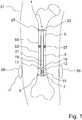
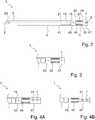
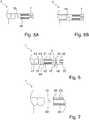
1 eine schematische Übersichtsskizze eines Marknagel zur Distraktion eines Röhrenknochens in Schnittansicht;2 eine schematische Schnittansicht eines Marknagels;3 eine schematische Schnittansicht eines Ausschnitts einer weiteren Ausführungsform eines Marknagels;4A eine schematische Schnittansicht eines Ausschnitts eines Marknagels mit einer dritten Verriegelungsöffnung;4B eine schematische Schnittansicht eines Ausschnitts eines Marknagels ohne Verriegelungsöffnung in einem Zwischenstück eines ersten Rohrs;5A eine schematische Schnittansicht eines Ausschnitts eines Marknagels, wobei eine erste Verriegelungsöffnung und eine zweite Verriegelungsöffnung zueinander verdreht sind;5B eine schematische Schnittansicht eines Ausschnitts eines Marknagels, wobei eine erste Verriegelungsöffnung und eine zweite Verriegelungsöffnung schräg zu der Längsachse des Marknagels ausgerichtet sind;6 eine schematische Schnittansicht eines Ausschnitts eines Marknagels mit einem mehrteiligen Endstück; und7 eine schematische Schnittansicht eines Ausschnitts eines Marknagels, wobei ein Dorn eines ersten Rohrs zu einem Zwischenstück hin eine radiale Ausrundung aufweist.
1 a schematic overview sketch of an intramedullary nail for distraction of a long bone in sectional view;2 a schematic sectional view of an intramedullary nail;3 a schematic sectional view of a detail of a further embodiment of an intramedullary nail;4A a schematic sectional view of a detail of an intramedullary nail with a third locking opening;4B a schematic sectional view of a section of an intramedullary nail without a locking opening in an intermediate piece of a first tube;5A a schematic sectional view of a detail of an intramedullary nail, a first locking opening and a second locking opening being rotated relative to one another;5B a schematic sectional view of a detail of an intramedullary nail, a first locking opening and a second locking opening being oriented obliquely to the longitudinal axis of the intramedullary nail;6th a schematic sectional view of a detail of an intramedullary nail with a multi-part end piece; and7th a schematic sectional view of a section of an intramedullary nail, a mandrel of a first tube having a radial fillet towards an intermediate piece.
Beschreibung der in den Figuren gezeigten AusführungsbeispieleDescription of the exemplary embodiments shown in the figures
Nachfolgend werden typische Ausführungsbeispiele der Erfindung beschrieben, wobei für gleiche oder ähnliche Teile teilweise gleiche Bezugszeichen verwendet werden und unter Umständen nicht mit jeder Figur nochmals erläutert werden. Die Erfindung ist nicht auf die nachfolgend beschriebenen typischen Ausführungsformen beschränkt. Zur Übersichtlichkeit sind teilweise nicht alle jeweiligen Merkmale mit einem Bezugszeichen versehen, insbesondere wenn Merkmale einem Element zugeordnet sind, welches einfach oder mehrfach die Längsachse des Marknagels umgreift, beispielsweise der Spulenkern mit dem Bezugszeichen
In der
Zwischen der ersten Verriegelungsöffnung
Die Spule
In dem Zwischenbereich zwischen dem Spulenbereich und dem zweiten Rohr
Zwischen dem zweiten Rohr
In dem zweiten Rohr
In weiteren Ausführungsbeispielen wird der Dorn direkt mit dem Endstück verschweißt, verklebt, oder auf andere Weise verbunden.In further exemplary embodiments, the mandrel is welded, glued, or otherwise connected directly to the end piece.
In dem Spulenbereich umfasst das erste Rohr
In der
Die radialen Auskragungen
Der Spulenkern
In der
In der
Die
In weiteren Ausführungsbeispielen ist kein Gewindeeinleger vorhanden. In solchen Ausführungsbeispielen wird ein Gewindeeinsatz nachträglich in den Kunststoff eingebracht, insbesondere eingedreht.In other exemplary embodiments, there is no thread insert. In such exemplary embodiments, a threaded insert is subsequently introduced into the plastic, in particular screwed in.
In
Die
Die Erfindung ist nicht auf die zuvor beschriebenen Ausführungsbeispiele beschränkt, vielmehr wird der Umfang der Erfindung durch die Ansprüche bestimmt. Insbesondere sind nicht alle dargestellten Teile notwendigerweise Merkmale der Erfindung, dies gilt in besonderem Maße für den dargestellten menschlichen Knochen.The invention is not restricted to the exemplary embodiments described above, rather the scope of the invention is determined by the claims. In particular, not all parts shown are necessarily features of the invention; this applies in particular to the human bone shown.
ZITATE ENTHALTEN IN DER BESCHREIBUNGQUOTES INCLUDED IN THE DESCRIPTION
Diese Liste der vom Anmelder aufgeführten Dokumente wurde automatisiert erzeugt und ist ausschließlich zur besseren Information des Lesers aufgenommen. Die Liste ist nicht Bestandteil der deutschen Patent- bzw. Gebrauchsmusteranmeldung. Das DPMA übernimmt keinerlei Haftung für etwaige Fehler oder Auslassungen.This list of the documents listed by the applicant was generated automatically and is included solely for the better information of the reader. The list is not part of the German patent or utility model application. The DPMA assumes no liability for any errors or omissions.
Zitierte PatentliteraturPatent literature cited
- EP 1033112 B1 [0002]EP 1033112 B1 [0002]
Claims (15)
Translated fromGermanPriority Applications (11)
| Application Number | Priority Date | Filing Date | Title |
|---|---|---|---|
| DE102019122354.7ADE102019122354A1 (en) | 2019-08-20 | 2019-08-20 | Intramedullary nail for distraction of a long bone |
| CN202080058348.XACN114340527B (en) | 2019-08-20 | 2020-08-20 | Intramedullary nail for long bone traction |
| JP2022506445AJP7533899B2 (en) | 2019-08-20 | 2020-08-20 | Intramedullary nails for lengthening long bones |
| BR112022003086ABR112022003086A2 (en) | 2019-08-20 | 2020-08-20 | Intramedullary nail for distraction of a long bone |
| CA3148724ACA3148724A1 (en) | 2019-08-20 | 2020-08-20 | Intramedullary nail for distracting a long bone |
| PCT/EP2020/073302WO2021032823A1 (en) | 2019-08-20 | 2020-08-20 | Intramedullary nail for distracting a long bone |
| ES20760803TES2941883T3 (en) | 2019-08-20 | 2020-08-20 | Intramedullary nail to distract a long bone |
| EP20760803.5AEP4017387B1 (en) | 2019-08-20 | 2020-08-20 | Intramedullary nail for distracting a long bone |
| US17/636,076US12324612B2 (en) | 2019-08-20 | 2020-08-20 | Intramedullary nail for distracting a long bone |
| ZA2022/01366AZA202201366B (en) | 2019-08-20 | 2022-01-28 | Intramedullary nail for distracting a long bone |
| IL290243AIL290243B1 (en) | 2019-08-20 | 2022-01-30 | Intramedullary nail for long bone treatment |
Applications Claiming Priority (1)
| Application Number | Priority Date | Filing Date | Title |
|---|---|---|---|
| DE102019122354.7ADE102019122354A1 (en) | 2019-08-20 | 2019-08-20 | Intramedullary nail for distraction of a long bone |
Publications (1)
| Publication Number | Publication Date |
|---|---|
| DE102019122354A1true DE102019122354A1 (en) | 2021-02-25 |
Family
ID=72193437
Family Applications (1)
| Application Number | Title | Priority Date | Filing Date |
|---|---|---|---|
| DE102019122354.7APendingDE102019122354A1 (en) | 2019-08-20 | 2019-08-20 | Intramedullary nail for distraction of a long bone |
Country Status (11)
| Country | Link |
|---|---|
| US (1) | US12324612B2 (en) |
| EP (1) | EP4017387B1 (en) |
| JP (1) | JP7533899B2 (en) |
| CN (1) | CN114340527B (en) |
| BR (1) | BR112022003086A2 (en) |
| CA (1) | CA3148724A1 (en) |
| DE (1) | DE102019122354A1 (en) |
| ES (1) | ES2941883T3 (en) |
| IL (1) | IL290243B1 (en) |
| WO (1) | WO2021032823A1 (en) |
| ZA (1) | ZA202201366B (en) |
Families Citing this family (3)
| Publication number | Priority date | Publication date | Assignee | Title |
|---|---|---|---|---|
| EP4529869A1 (en) | 2023-09-28 | 2025-04-02 | Orthofix S.r.l. | Intramedullary nail for a long bone |
| WO2025083150A1 (en) | 2023-10-19 | 2025-04-24 | Orthofix S.R.L. | Motorized and improved intramedullary nail for bone lengthening or transport |
| WO2025093360A1 (en) | 2023-10-31 | 2025-05-08 | Orthofix S.R.L. | Motorized intramedullary nail for bone lengthening or transport |
Citations (8)
| Publication number | Priority date | Publication date | Assignee | Title |
|---|---|---|---|---|
| DE19700225A1 (en)* | 1997-01-07 | 1998-07-09 | Augustin Prof Dr Betz | Distraction device for moving two parts of a bone apart |
| EP1033112B1 (en)* | 1999-03-01 | 2003-10-08 | Baumgart, Rainer, Dipl.-Ing. Dr. med. | Intramedullary nail for bone distraction |
| DE10340025A1 (en)* | 2003-08-28 | 2005-03-24 | Wittenstein Ag | Surgical device for bone extension, comprising planetary gear acting on outer sleeve serving as ring gear |
| WO2012051512A1 (en)* | 2010-10-14 | 2012-04-19 | Virginia Tech Intellectual Properties, Inc. | Intramedullary nail targeting device |
| DE102015109624A1 (en)* | 2015-06-16 | 2016-12-22 | Wittenstein Se | Mechatronic implant |
| US20170244287A1 (en)* | 2014-10-17 | 2017-08-24 | Synoste Oy | A device with a receiving antenna and a related power transfer system |
| US20170333080A1 (en)* | 2014-10-23 | 2017-11-23 | Ellipse Technologies, Inc. | Remotely Adjustable Interactive Bone Reshaping Implant |
| US20180353214A1 (en)* | 2004-07-02 | 2018-12-13 | Nuvasive Specialized Orthopedics, Inc. | Expandable rod system to treat scoliosis and method of using the same |
Family Cites Families (18)
| Publication number | Priority date | Publication date | Assignee | Title |
|---|---|---|---|---|
| US5415660A (en)* | 1994-01-07 | 1995-05-16 | Regents Of The University Of Minnesota | Implantable limb lengthening nail driven by a shape memory alloy |
| US6033412A (en)* | 1997-04-03 | 2000-03-07 | Losken; H. Wolfgang | Automated implantable bone distractor for incremental bone adjustment |
| DE19906423A1 (en)* | 1999-02-16 | 2000-08-17 | Wittenstein Gmbh & Co Kg | Active marrow spike for drawing out sections of bone consists of two elements moving against each other and electrically operated driving element to supply spike with electrical energy via detachable plug-in element. |
| EP1395186A1 (en) | 2001-05-23 | 2004-03-10 | Yona Kosashvili | Magnetically-actuable intramedullary device |
| DE10156316A1 (en)* | 2001-11-19 | 2003-06-05 | Wittenstein Ag | distraction |
| FR2843875B1 (en)* | 2002-08-30 | 2004-10-08 | Arnaud Andre Soubeiran | IMPLANTABLE DEVICE FOR TRANSFORMING ON DEMAND ALTERNATE COUPLES APPLIED BY MUSCLE FORCE BETWEEN TWO WORKPIECES IN A MOVEMENT OF TWO BODIES RELATIVELY TO ONE ANOTHER |
| DE102006018191B4 (en)* | 2006-04-19 | 2008-08-07 | Neue Magnetodyn Gmbh | Electric intramedullary nail system |
| US7753915B1 (en)* | 2007-06-14 | 2010-07-13 | August Eksler | Bi-directional bone length adjustment system |
| JP5295827B2 (en) | 2008-03-24 | 2013-09-18 | 京セラメディカル株式会社 | In vivo actuator and bone adjustment device |
| WO2010134078A1 (en)* | 2009-05-18 | 2010-11-25 | Orthogon Technologies 2003 | An intramedullary nail device |
| JP5751642B2 (en)* | 2009-09-04 | 2015-07-22 | エリプス テクノロジーズ, インク.Ellipse Technologies, Inc. | Bone growth apparatus and method |
| CN102917659B (en)* | 2010-03-19 | 2016-04-20 | 史密夫和内修有限公司 | Telescoping Intramedullary Nails and Actuation Mechanisms |
| US9308089B2 (en)* | 2011-06-27 | 2016-04-12 | University Of Cape Town | Endoprosthesis |
| DE102011053638A1 (en)* | 2011-09-15 | 2013-03-21 | Wittenstein Ag | Mark Nagel |
| US20130165733A1 (en)* | 2011-12-27 | 2013-06-27 | Richard A. Rogachefsky | Orthopedic fixation device with magnetic field generator |
| EP2915496B2 (en)* | 2014-03-06 | 2024-06-26 | MPS Micro Precision Systems AG | Implantable device |
| BR112018015504A2 (en)* | 2016-01-28 | 2018-12-18 | Nuvasive Specialized Orthopedics, Inc. | bone transport systems |
| CN108143477B (en)* | 2017-12-18 | 2020-05-19 | 武汉大学 | Intramedullary bone lengthening device using memory alloy spring electromagnetic heating |
- 2019
- 2019-08-20DEDE102019122354.7Apatent/DE102019122354A1/enactivePending
- 2020
- 2020-08-20BRBR112022003086Apatent/BR112022003086A2/enunknown
- 2020-08-20ESES20760803Tpatent/ES2941883T3/enactiveActive
- 2020-08-20CACA3148724Apatent/CA3148724A1/enactivePending
- 2020-08-20USUS17/636,076patent/US12324612B2/enactiveActive
- 2020-08-20JPJP2022506445Apatent/JP7533899B2/enactiveActive
- 2020-08-20EPEP20760803.5Apatent/EP4017387B1/enactiveActive
- 2020-08-20WOPCT/EP2020/073302patent/WO2021032823A1/ennot_activeCeased
- 2020-08-20CNCN202080058348.XApatent/CN114340527B/enactiveActive
- 2022
- 2022-01-28ZAZA2022/01366Apatent/ZA202201366B/enunknown
- 2022-01-30ILIL290243Apatent/IL290243B1/enunknown
Patent Citations (8)
| Publication number | Priority date | Publication date | Assignee | Title |
|---|---|---|---|---|
| DE19700225A1 (en)* | 1997-01-07 | 1998-07-09 | Augustin Prof Dr Betz | Distraction device for moving two parts of a bone apart |
| EP1033112B1 (en)* | 1999-03-01 | 2003-10-08 | Baumgart, Rainer, Dipl.-Ing. Dr. med. | Intramedullary nail for bone distraction |
| DE10340025A1 (en)* | 2003-08-28 | 2005-03-24 | Wittenstein Ag | Surgical device for bone extension, comprising planetary gear acting on outer sleeve serving as ring gear |
| US20180353214A1 (en)* | 2004-07-02 | 2018-12-13 | Nuvasive Specialized Orthopedics, Inc. | Expandable rod system to treat scoliosis and method of using the same |
| WO2012051512A1 (en)* | 2010-10-14 | 2012-04-19 | Virginia Tech Intellectual Properties, Inc. | Intramedullary nail targeting device |
| US20170244287A1 (en)* | 2014-10-17 | 2017-08-24 | Synoste Oy | A device with a receiving antenna and a related power transfer system |
| US20170333080A1 (en)* | 2014-10-23 | 2017-11-23 | Ellipse Technologies, Inc. | Remotely Adjustable Interactive Bone Reshaping Implant |
| DE102015109624A1 (en)* | 2015-06-16 | 2016-12-22 | Wittenstein Se | Mechatronic implant |
Also Published As
| Publication number | Publication date |
|---|---|
| ES2941883T3 (en) | 2023-05-26 |
| US12324612B2 (en) | 2025-06-10 |
| BR112022003086A2 (en) | 2022-05-17 |
| US20220287745A1 (en) | 2022-09-15 |
| EP4017387B1 (en) | 2023-02-08 |
| EP4017387A1 (en) | 2022-06-29 |
| JP2022545338A (en) | 2022-10-27 |
| CN114340527A (en) | 2022-04-12 |
| CN114340527B (en) | 2025-02-11 |
| JP7533899B2 (en) | 2024-08-14 |
| CA3148724A1 (en) | 2021-02-25 |
| ZA202201366B (en) | 2022-09-28 |
| IL290243A (en) | 2022-03-01 |
| IL290243B1 (en) | 2025-07-01 |
| WO2021032823A1 (en) | 2021-02-25 |
Similar Documents
| Publication | Publication Date | Title |
|---|---|---|
| DE102019122354A1 (en) | Intramedullary nail for distraction of a long bone | |
| EP1847227B1 (en) | Electric medullar nail system | |
| EP2570092B1 (en) | Marrow nail | |
| DE814490C (en) | Electronic amplifier | |
| EP2990002B1 (en) | Intramedullary nail | |
| DE10307814B4 (en) | Gradient coils and method for producing gradient coils for MRI systems | |
| DE2314573A1 (en) | DEVICE FOR PROMOTING HEALING PROCESSES | |
| DE69616611T2 (en) | Ferritkernmarkierung | |
| DE102018005690A1 (en) | Flexible double helix intramedullary nail | |
| DE10219767B4 (en) | Magnetic resonance imaging apparatus with a vacuum-cast body coil | |
| EP2200052B1 (en) | Electricity-compensated throttle and method for producing an electricity-compensated throttle | |
| DE102004005278B4 (en) | A method of fabricating transversal non-cylindrical gradient coils having at least one divergent section | |
| DE102019219755B4 (en) | Gradient coil unit for a magnetic resonance device | |
| DE102006027447A1 (en) | Modular linear accelerator | |
| EP1233279A2 (en) | Device for magnetic resonance imaging with open magnet system | |
| DE19609645C2 (en) | Method of making a gradient coil | |
| DE10247228B4 (en) | Method and device for magnetizing a permanent magnet ring magnet with an even number of poles | |
| DE102005013853A1 (en) | Magnetic resonance plant comprises a gradient coil and a high frequency transmitting antenna with investigation object arranged in an investigation volume to energizing magnetic resonance | |
| DE102013111354A1 (en) | Internal fixator for insertion in medullary cavity of femur to e.g. correct knock-knees, has elements movable relative to each other by working device, which includes solid body actuator i.e. magnetic shape memory alloy | |
| DE10109489A1 (en) | Nuclear magnetic resonance device with a static magnetic field, which is also capable of operating with two resonance frequencies has an arrangement of eigen frequencies that enables better frequency damping | |
| DE102007016313B4 (en) | Whole body antenna for a magnetic resonance system and magnetic resonance system with such a whole body antenna | |
| EP3138110B1 (en) | Plunger coil, treaded spindel therefor and method of manufacturing thereof | |
| EP4412550A1 (en) | Device for moving a magnetic object in a container | |
| DE102022134393A1 (en) | Actively cooled field former with permanently connected coolant lines | |
| DE102021210454A1 (en) | Inductor for inductive hardening of metallic materials and manufacturing method for an inductor |
Legal Events
| Date | Code | Title | Description |
|---|---|---|---|
| R163 | Identified publications notified | ||
| R081 | Change of applicant/patentee | Owner name:ORTHOFIX SRL, IT Free format text:FORMER OWNER: WITTENSTEIN SE, 97999 IGERSHEIM, DE | |
| R082 | Change of representative | Representative=s name:ZIMMERMANN & PARTNER PATENTANWAELTE MBB, DE |