DE102019117097A1 - DEVICE AND METHOD FOR OPTIMIZING THE PROCESS TIME OF A PRODUCTION MACHINE - Google Patents
DEVICE AND METHOD FOR OPTIMIZING THE PROCESS TIME OF A PRODUCTION MACHINEDownload PDFInfo
- Publication number
- DE102019117097A1 DE102019117097A1DE102019117097.4ADE102019117097ADE102019117097A1DE 102019117097 A1DE102019117097 A1DE 102019117097A1DE 102019117097 ADE102019117097 ADE 102019117097ADE 102019117097 A1DE102019117097 A1DE 102019117097A1
- Authority
- DE
- Germany
- Prior art keywords
- time
- speed
- machine
- determining
- station
- Prior art date
- Legal status (The legal status is an assumption and is not a legal conclusion. Google has not performed a legal analysis and makes no representation as to the accuracy of the status listed.)
- Withdrawn
Links
Images


Classifications
- G—PHYSICS
- G05—CONTROLLING; REGULATING
- G05B—CONTROL OR REGULATING SYSTEMS IN GENERAL; FUNCTIONAL ELEMENTS OF SUCH SYSTEMS; MONITORING OR TESTING ARRANGEMENTS FOR SUCH SYSTEMS OR ELEMENTS
- G05B19/00—Programme-control systems
- G05B19/02—Programme-control systems electric
- G05B19/418—Total factory control, i.e. centrally controlling a plurality of machines, e.g. direct or distributed numerical control [DNC], flexible manufacturing systems [FMS], integrated manufacturing systems [IMS] or computer integrated manufacturing [CIM]
- G05B19/41865—Total factory control, i.e. centrally controlling a plurality of machines, e.g. direct or distributed numerical control [DNC], flexible manufacturing systems [FMS], integrated manufacturing systems [IMS] or computer integrated manufacturing [CIM] characterised by job scheduling, process planning, material flow
- G—PHYSICS
- G05—CONTROLLING; REGULATING
- G05B—CONTROL OR REGULATING SYSTEMS IN GENERAL; FUNCTIONAL ELEMENTS OF SUCH SYSTEMS; MONITORING OR TESTING ARRANGEMENTS FOR SUCH SYSTEMS OR ELEMENTS
- G05B2219/00—Program-control systems
- G05B2219/30—Nc systems
- G05B2219/32—Operator till task planning
- G05B2219/32015—Optimize, process management, optimize production line
- G—PHYSICS
- G05—CONTROLLING; REGULATING
- G05B—CONTROL OR REGULATING SYSTEMS IN GENERAL; FUNCTIONAL ELEMENTS OF SUCH SYSTEMS; MONITORING OR TESTING ARRANGEMENTS FOR SUCH SYSTEMS OR ELEMENTS
- G05B2219/00—Program-control systems
- G05B2219/30—Nc systems
- G05B2219/32—Operator till task planning
- G05B2219/32128—Gui graphical user interface
- G—PHYSICS
- G05—CONTROLLING; REGULATING
- G05B—CONTROL OR REGULATING SYSTEMS IN GENERAL; FUNCTIONAL ELEMENTS OF SUCH SYSTEMS; MONITORING OR TESTING ARRANGEMENTS FOR SUCH SYSTEMS OR ELEMENTS
- G05B2219/00—Program-control systems
- G05B2219/30—Nc systems
- G05B2219/32—Operator till task planning
- G05B2219/32304—Minimize flow time, tact, shortest processing, machining time
- G—PHYSICS
- G05—CONTROLLING; REGULATING
- G05B—CONTROL OR REGULATING SYSTEMS IN GENERAL; FUNCTIONAL ELEMENTS OF SUCH SYSTEMS; MONITORING OR TESTING ARRANGEMENTS FOR SUCH SYSTEMS OR ELEMENTS
- G05B2219/00—Program-control systems
- G05B2219/30—Nc systems
- G05B2219/35—Nc in input of data, input till input file format
- G05B2219/35512—Display entered, measured values with bargraph
- G—PHYSICS
- G05—CONTROLLING; REGULATING
- G05B—CONTROL OR REGULATING SYSTEMS IN GENERAL; FUNCTIONAL ELEMENTS OF SUCH SYSTEMS; MONITORING OR TESTING ARRANGEMENTS FOR SUCH SYSTEMS OR ELEMENTS
- G05B2219/00—Program-control systems
- G05B2219/30—Nc systems
- G05B2219/40—Robotics, robotics mapping to robotics vision
- G05B2219/40161—Visual display of machining, operation, remote viewing
- Y—GENERAL TAGGING OF NEW TECHNOLOGICAL DEVELOPMENTS; GENERAL TAGGING OF CROSS-SECTIONAL TECHNOLOGIES SPANNING OVER SEVERAL SECTIONS OF THE IPC; TECHNICAL SUBJECTS COVERED BY FORMER USPC CROSS-REFERENCE ART COLLECTIONS [XRACs] AND DIGESTS
- Y02—TECHNOLOGIES OR APPLICATIONS FOR MITIGATION OR ADAPTATION AGAINST CLIMATE CHANGE
- Y02P—CLIMATE CHANGE MITIGATION TECHNOLOGIES IN THE PRODUCTION OR PROCESSING OF GOODS
- Y02P90/00—Enabling technologies with a potential contribution to greenhouse gas [GHG] emissions mitigation
- Y02P90/02—Total factory control, e.g. smart factories, flexible manufacturing systems [FMS] or integrated manufacturing systems [IMS]
Landscapes
- Engineering & Computer Science (AREA)
- General Engineering & Computer Science (AREA)
- Manufacturing & Machinery (AREA)
- Quality & Reliability (AREA)
- Physics & Mathematics (AREA)
- General Physics & Mathematics (AREA)
- Automation & Control Theory (AREA)
- General Factory Administration (AREA)
- Management, Administration, Business Operations System, And Electronic Commerce (AREA)
Abstract
Translated fromGermanDescription
Translated fromGermanGebiet der ErfindungField of invention
Die Erfindung betrifft eine Produktionsmaschine mit einem Steuerungsprogramm zur Visualisierung von Stationen und/oder Maschinenkomponenten unter Hervorhebung der geschwindigkeitsbestimmenden Station und/oder der geschwindigkeitsbestimmenden Maschinenkomponente zur Optimierung der Prozesszeit. Die Erfindung betrifft zudem einem Verfahren zum Optimieren der Prozesszeit für eine Produktionsmaschine mit einem solchen Steuerungsprogramm sowie einem Datenträger mit einem solchen Steuerungsprogramm.The invention relates to a production machine with a control program for visualizing stations and / or machine components with emphasis on the speed-determining station and / or the speed-determining machine component for optimizing the process time. The invention also relates to a method for optimizing the process time for a production machine with such a control program and a data carrier with such a control program.
Hintergrund der ErfindungBackground of the invention
Produktionsmaschinen mit mehreren Stationen werden in vielen Bereichen der Fertigung eingesetzt. Diese Stationen bestehen in der Regel aus mehreren Baugruppen unter Verwendung produktspezifischer Werkzeuge. In der Kunststoffverarbeitung werden beispielweise als primär formerzeugende Stationen Blasformstationen oder Thermoformstationen verwendet. Weitere Stationen im Rahmen einer Produktionsmaschine können eine Stanze, eine Lochstanze oder eine Stapelung sein. Der eigentliche Produktionsprozess wird durch Prozessparameter definiert, die als maschinenübergreifende Parameter die Zusammenarbeit der unterschiedlichen Stationen steuern oder innerhalb einer Station die Arbeitsprozesse der einzelnen Bauteile und Werkzeuge. Diese Prozessparameter definieren in ihrer Gesamtheit den (üblicherweise zyklischen) Prozessablauf und bilden so ein Produktionsprogramm, das auch als Rezept bezeichnet wird.Production machines with several stations are used in many areas of production. These stations usually consist of several assemblies using product-specific tools. In plastics processing, for example, blow molding stations or thermoforming stations are used as the primary form-generating stations. Further stations in the context of a production machine can be a punch, a punch or a stack. The actual production process is defined by process parameters which, as cross-machine parameters, control the cooperation between the different stations or the work processes of the individual components and tools within a station. In their entirety, these process parameters define the (usually cyclical) process sequence and thus form a production program, which is also referred to as a recipe.
Im Stand der Technik sind Verfahren und Vorrichtungen zur Visualisierung des Produktionsprogramms als Ablaufdiagramm bekannt. Hierbei wird der Prozessablauf schematische unter Angabe der beteiligten Stationen bzw. Baugruppen/Werkzeuge angezeigt, wobei die einzelnen, den Komponenten oder Werkzeugen zugeordneten Prozessschritte als Balken gegenüber der Zeit aufgetragen sind.In the prior art, methods and devices for visualizing the production program as a flow chart are known. The process sequence is shown schematically, specifying the stations or assemblies / tools involved, with the individual process steps assigned to the components or tools being plotted against time as bars.
Das Produktionsprogramm soll einerseits die Herstellung eines qualitativ hochwertigen Produkts in reproduzierbarer Weise erlauben, andererseits auch die Produktionszeit minimieren. Bei komplex aufgebauten Produktionsprogrammen mit vielen Bauteilen/Werkzeugen und evtl. mehreren Stationen ist es für den Bediener äußerst schwierig die geschwindigkeitsbestimmenden Prozessabläufe zu identifizieren, zumal einzelnen Prozessschritte mit den beteiligten Baugruppen/Werkzeugen nicht nur konsekutiv ablaufen, sondem zum Teil auch parallel oder in überlappender Weise. Hinzu kommt, dass neben der eigentlichen Wirkzeit auch weitere Prozesszeiten wie Verzögerungszeit, Fahrzeit oder Vorhaltezeit als parametrisierende Zeitphasen vorliegen. Zudem sind üblicherweise Freigaben definiert, um kritische Prozessschnittstellen zu berücksichtigen. Der Fachmann hat daher trotz schematischer Visualisierung mittels Ablaufdiagramm keine objektive Basis für eine Zeitoptimierung des Prozessprogramms und damit des Herstellungsprozesses. Er muss hier auf seine individuelle Erfahrung zurückgreifen und in einem „Trial-and-error“-Ansatz, der üblicherweise auch eine Inbetriebnahme der Produktionsmaschine erfordert, versuchen, den Prozess hinsichtlich der Prozesszeit zu optimieren.The production program should, on the one hand, allow the production of a high quality product in a reproducible manner, and on the other hand also minimize the production time. In the case of complex production programs with many components / tools and possibly several stations, it is extremely difficult for the operator to identify the process sequences that determine the speed, especially since individual process steps with the assemblies / tools involved do not only run consecutively, but sometimes also in parallel or in an overlapping manner . In addition, in addition to the actual active time, other process times such as delay time, travel time or lead time are also available as parameterizing time phases. In addition, releases are usually defined to take critical process interfaces into account. The person skilled in the art therefore has no objective basis for optimizing the time of the process program and thus of the manufacturing process despite the schematic visualization using a flowchart. He has to fall back on his individual experience and try to optimize the process with regard to the process time using a "trial and error" approach, which usually also requires commissioning of the production machine.
Es wäre daher wünschenswert, die zeitliche Optimierung des Prozessablaufs auf eine objektivere Basis zu stellen und eine Prozessvisualisierung dem Benutzer zur Verfügung zu stellen, mit der er unabhängig von seiner Erfahrung schneller zu einem für die Produktion zeitlich verbesserten Prozessparametersatz gelangen kann.It would therefore be desirable to put the temporal optimization of the process sequence on a more objective basis and to provide the user with a process visualization with which he can more quickly arrive at a process parameter set that is improved over time for production, regardless of his experience.
Zusammenfassung der ErfindungSummary of the invention
Der Erfindung liegt die Aufgabe zugrunde, ein Steuerungsprogramm für Produktionsmaschinen zur Verfügung zu stellen, mit denen die zeitliche Optimierung des Prozessparametersatzes auf einer objektiveren Basis erfolgt und eine Prozessvisualisierung dem Benutzer zur Verfügung gestellt wird, mit der er unabhängig von seiner Erfahrung zielgerichtet und damit schneller zu einem für die Produktion zeitlich verbesserten Prozessparametersatz gelangen kann.The invention is based on the object of providing a control program for production machines with which the temporal optimization of the process parameter set takes place on a more objective basis and a process visualization is made available to the user, with which he can target-oriented and thus faster regardless of his experience a set of process parameters that is improved over time for production.
Die Aufgabe der Erfindung wird gelöst durch eine Produktionsmaschine gemäß Anspruch 1 und ein Verfahren gemäß Anspruch 11. Weitere vorteilhafte Ausgestaltungen der Produktionsmaschine sind Gegenstand der abhängigen Ansprüche 2 bis 10. Weitere vorteilhafte Ausgestaltungen des Verfahrens sind Gegenstand der abhängigen Ansprüche 11 bis 19.The object of the invention is achieved by a production machine according to
In einem ersten Aspekt betrifft die Erfindung eine Produktionsmaschine, umfassend eine oder mehrere Stationen (
Produktionsmaschinen für die Kunststoffverarbeitung sind beispielsweise Blasformmaschinen oder Thermoformmaschinen. Blasformmaschinen stellen einen Folienschlauch aus erwärmtem Kunststoffmaterial her. Thermoformmaschinen werden zur Produktion von tiefgezogenen Formteilen umfassend eine Transporteinrichtung für eine thermoplastische Folienbahn und eine Formstation zum Formen der Formteile aus der zuvor erwärmten Folienbahn verwendet. Solche Maschinen zeichnen sich dadurch aus, dass sie eine Vielzahl an einzelnen Maschinenkomponenten umfassen, die geeignet zusammenwirken müssen, da ein einziger Folienschlauch bzw. eine einzige Folienbahn durch die gesamte Produktionsanlage hindurchgeführt wird und somit die Maschinenkomponenten für einen guten Gesamtprozess in ihrer Wirkung und Taktzeit aufeinander abgestimmt werden müssen. Maschinenkomponenten für eine Thermoformmaschine umfassen beispielsweise die Transportvorrichtung für Folienversorgung von einer Folienrolle, eine Vorheizstation zum Vorheizen der Folienbahn, eine Heizstation zum Heizen der Folienbahn auf Prozesstemperatur, eine Formstation zum Formen des Produktes aus der Folienbahn, eine Schneidestation zur Herausschneiden der geformten Produkte aus der Folienbahn, eine Stapelstation zur Stapelung der fertigen Produkte und eine Verwertungsstation für die nicht verarbeitete Folienbahn.Production machines for plastics processing are for example Blow molding machines or thermoforming machines. Blow molding machines produce a film tube from heated plastic material. Thermoforming machines are used for the production of deep-drawn molded parts comprising a transport device for a thermoplastic film web and a forming station for forming the molded parts from the previously heated film web. Such machines are characterized by the fact that they comprise a large number of individual machine components that have to work together in a suitable manner, since a single tube of film or a single sheet of film is passed through the entire production system and thus the machine components for a good overall process in terms of their effect and cycle time need to be coordinated. Machine components for a thermoforming machine include, for example, the transport device for film supply from a film roll, a preheating station for preheating the film web, a heating station for heating the film web to process temperature, a forming station for forming the product from the film web, a cutting station for cutting out the formed products from the film web , a stacking station for stacking the finished products and a recycling station for the unprocessed film web.
Die Maschinensteuerung kann dabei an der Produktionsmaschine oder separat von der Produktionsmaschine angeordnet sein, wobei die Maschinensteuerung über geeignete Datenleitungen mit den jeweiligen Maschinenkomponenten so verbunden ist, dass die Eingaben der Prozessparameter in entsprechende Maschineneinstellungen umgesetzt werden können. Die Maschinesteuerung umfasst außerdem einen Prozessor, auf dem das Steuerungsprogramm installiert und ausgeführt werden kann sowie einen Datenspeicher zur Speicherung von Prozessparameter oder ist zumindest mit einem solchen Speicher verbunden. Die Datenleitungen können dabei als Datenkabel oder drahtlos ausgeführt sein. Die Maschinesteuerung kann beispielsweise auch als Cloudlösung implementiert sein, die über ein WLAN oder eine Internetverbindung mit der Produktionsmaschine verbunden ist.The machine control can be arranged on the production machine or separately from the production machine, the machine control being connected to the respective machine components via suitable data lines in such a way that the inputs of the process parameters can be converted into corresponding machine settings. The machine control also includes a processor on which the control program can be installed and executed, and a data memory for storing process parameters or is at least connected to such a memory. The data lines can be designed as data cables or wireless. The machine control can, for example, also be implemented as a cloud solution that is connected to the production machine via a WLAN or an Internet connection.
Stationen im Sinne der Erfindung sind funktionell zusammenhängende Einzelmaschinen der Gesamtmaschinen. Beispiele hier sind eine Stapelmaschine oder eine Stanze. Die Bestandteile dieser Stationen werden als Maschinenkomponenten bezeichnet. Beispielsweise umfasst bei einer Thermoformmaschine als Produktionsmaschine die Station „Formstation“ als Maschinenkomponenten ein Oberwerkzeug und ein Unterwerkzeug, zwischen denen die Folienbahn für den Formprozess eingespannt wird und gegebenenfalls Vordehnstempel, die die Folie beim Formprozess vordehnen.Stations within the meaning of the invention are functionally interrelated individual machines of the overall machines. Examples here are a stacking machine or a punch. The components of these stations are called machine components. For example, in a thermoforming machine as a production machine, the “forming station” station comprises as machine components an upper tool and a lower tool, between which the film web is clamped for the forming process and, if necessary, pre-stretching dies that pre-stretch the film during the forming process.
In einer weiteren Ausführungsform der Erfindung erfolgt bei der der Produktionsmaschine die Hervorhebung der geschwindigkeitsbestimmenden Station und/oder die geschwindigkeitsbestimmende Maschinenkomponente durch eine oder mehrere der im Folgenden aufgelisteten Visualisierungsformen
- Visualisierungsform 1: Bei dieser Visualisierungsform wird im Ablaufdiagramm eine bezüglich senkrecht zur t-Achse des Ablaufdiagramms verlaufende Linie angezeigt, die den Balken der geschwindigkeitsbestimmenden Station oder der geschwindigkeitsbestimmenden Maschinenkomponente in dem t-Wert schneidet, bei dem der Prozessbalken dieser Station oder dieser Maschinenkomponente im Ablaufdiagramm endet. Dies hat den Vorteil, dass der Benutzer auf den ersten Blick die zeitliche Einbettung der geschwindigkeitsbestimmenden Station/Maschinenkomponente in den Gesamtprozess erfasst und damit leichter Maßnahmen zur Prozessoptimierung ergreifen kann,
- Visualisierungsform 2: Bei dieser Visualisierungsform erfolgt die visuelle Hervorhebung von bereits im Ablaufdiagramm vorhandenen Verknüpfungen, wie einem Zeiger, der das Ende eines ersten geschwindigkeitsbestimmenden Prozessschrittes mit dem Beginn eines zweiten Prozessschritts verknüpft und eine Freigabe definiert. Damit ist für den Benutzer auch die prozedurale Einbettung in den Gesamtprozess sofort ersichtlich.
- Visualisierungsform 2: Bei dieser Visualisierungsform erfolgt eine numerische Angabe der Verzögerungszeit. Dadurch hat der Benutzer sofort einen Hinweis auf die maximal einsparbare Zeit, die er hier durch Prozessanpassung erreichen kann.
- Visualisierungsform 3: Bei dieser Visualisierungsform erfolgt eine Wiedergabe des Namens der geschwindigkeitsbestimmenden Station oder des geschwindigkeitsbestimmenden Schritts in einer Signalfarbe wie Gelb, Orange oder Rot. Dies erlaubt nicht nur eine sofortige Identifizierung der betreffenden geschwindigkeitsbestimmenden Station oder Maschinenkomponente, sondern verringert auch die Chance einer Fehlinterpretation mit anschließender Fehlbedienung.
- Visualisierungsform 3: Bei dieser Visualisierungsform erfolgt die Verknüpfung der geschwindigkeitsbestimmenden Station oder des geschwindigkeitsbestimmenden Schrittes mit einem grafischen Symbol, wie beispielsweise einem Zifferblatt mit Zeigern. Derartige Symbole haben den Vorteil, dass sie eine intuitive Erfassung des Sachverhalts leisten und auch international verwendbar sind.
- Visualization form 1: With this visualization form, a line running perpendicular to the t-axis of the flowchart is displayed in the flowchart, which line intersects the bar of the speed-determining station or the speed-determining machine component in the t-value at which the process bar of this station or this machine component in the flowchart ends. This has the advantage that the user can see at a glance how the speed-determining station / machine component is embedded in the overall process and can thus more easily take measures to optimize the process.
- Form of visualization 2: With this form of visualization, links already present in the flowchart are visually highlighted, such as a pointer that links the end of a first speed-determining process step with the start of a second process step and defines a release. The procedural embedding in the overall process is thus immediately apparent to the user.
- Visualization form 2: With this visualization form, the delay time is specified numerically. This gives the user an immediate indication of the maximum amount of time that can be saved by making process adjustments.
- Visualization form 3: With this visualization form, the name of the speed-determining station or the speed-determining step is displayed in a signal color such as yellow, orange or red. This not only allows the relevant speed-determining station or machine component to be identified immediately, but also reduces the chance of misinterpretation subsequent incorrect operation.
- Form of visualization 3: In this form of visualization, the speed-determining station or the speed-determining step is linked with a graphic symbol, such as a dial with pointers. Such symbols have the advantage that they provide an intuitive grasp of the facts and can also be used internationally.
In einer weiteren Ausführungsform ist bei der erfindungsgemäßen Produktionsmaschine das Steuerungsprogramm zusätzlich dazu ausgestaltet, auf der Visualisierungseinrichtung die Zeitphasen der von der Maschinenkomponente durchgeführten Prozessabläufe anzuzeigen. Im Rahmen der vorliegenden Anmeldung ist eine Zeitphase als ein Zeitabschnitt definiert, in dem ein bestimmter Prozess von einer Maschinenkomponente oder Station durchgeführt wird. Er besitzt somit einen definierten Beginn und ein definiertes Ende, die damit eine Phasenlänge definieren.In a further embodiment, the control program in the production machine according to the invention is also designed to display the time phases of the process sequences carried out by the machine component on the visualization device. In the context of the present application, a time phase is defined as a time segment in which a specific process is carried out by a machine component or station. It thus has a defined beginning and a defined end, which thus define a phase length.
Die Visualisierung der Zeitphasen geschieht bevorzugt durch eine zeilenweise Anordnung der Maschinenkomponenten mit der Zeitachse als horizontale Achse und einer Darstellung der Zeitphasen als visuell unterscheidbare Abschnitte eines Zeitstrahls in der Zeile der jeweiligen Maschinenkomponente. Eine solche Darstellung der Zeitphasen als Abschnitte eines Zeitstrahls erfolgt zweckmäßigerweise als Balkendiagramm.The visualization of the time phases is preferably done by arranging the machine components line by line with the time axis as the horizontal axis and a representation of the time phases as visually distinguishable sections of a time line in the line of the respective machine component. Such a representation of the time phases as sections of a time line is expediently carried out as a bar chart.
Zweckmäßigerweise werden die Zeitphasen gemäß dem zugeordneten Prozessschritt einem bestimmten Zeitphasentyp zugeordnet. Nichteinschränkende Beispiele für derartige Zeitphasentypen sind Wirkzeit, Verzögerungszeit, Fahrzeit und Vorhaltezeit. So beschreibt beispielsweise die Wirkzeit diejenige Zeitphase, in der eine Maschinenkomponente auf das zu bearbeitende Werkstück einwirkt, wohingegen die Fahrzeit diejenige Zeit charakterisiert, bei der die Maschinenkomponente auf das Werkstück zugefahren oder von diesem weggefahren wird.The time phases are expediently assigned to a specific time phase type in accordance with the assigned process step. Non-limiting examples of such time phase types are action time, delay time, travel time and lead time. For example, the action time describes the time phase in which a machine component acts on the workpiece to be machined, whereas the travel time characterizes the time in which the machine component is approached or moved away from the workpiece.
In einer bevorzugten Ausführungsform der Erfindung ist bei der Produktionsmaschine die Visualisierungseinrichtung als interaktive Benutzerschnittstelle eingerichtet. Bevorzugt ist hierbei eine Ausbildung als berührungsempfindlicher Bildschirm.In a preferred embodiment of the invention, the visualization device is set up as an interactive user interface in the production machine. A design as a touch-sensitive screen is preferred here.
In einer Ausführungsform der Erfindung ist bei der Produktionsmaschine das Steuerungsprogramm zusätzlich dazu ausgestaltet, auf der Visualisierungseinrichtung eine Benutzerhilfe bereitzustellen, die bevorzugt durch Berühren/Anklicken der visuellen Hervorhebungen der geschwindigkeitsbestimmenden Station oder der geschwindigkeitsbestimmenden Maschinenkomponente geöffnet werden kann. Besonders bevorzugt ist hierbei, dass die Benutzerhilfe Vorschläge zur Zeitoptimierung des Prozesses beinhaltet. Bevorzugt ist hier eine Ausgestaltung als separates Programmfenster, das sich durch das benutzerseitige Aufrufen innerhalb des vorhandenen Programmfensters öffnet (sog. Popup-Menü).In one embodiment of the invention, the control program of the production machine is additionally designed to provide a user help on the visualization device, which can preferably be opened by touching / clicking the visual highlighting of the speed-determining station or the speed-determining machine component. It is particularly preferred here that the user help contains suggestions for optimizing the time of the process. A configuration as a separate program window is preferred here, which opens when the user calls it up within the existing program window (so-called pop-up menu).
In einer besonderen Ausführungsform ist bei der Produktionsmaschine (
In bevorzugter Weise ist für das Schaltfeld eine oder mehrere der folgenden Visualisierungsformen vorgesehen:
- • Die Schaltfelder werden in einem separaten Fenster dargestellt, das als Kontextmenü damit die umfassende Eingabe von Zeitwerten für die ausgewählte Station oder Maschinenkomponente erlaubt.
- • Die Schaltfelder einer Maschinenkomponente sind in der entsprechenden Zeile der Maschinenkomponente angeordnet. Dies erlaubt die intuitive Zuordnung und einfache Werteeingabe.
- • Die Abfolge der Schaltfelder innerhalb einer Zeile entspricht der Abfolge der dadurch steuerbaren Zeitphasen der Maschinenkomponente. Auch dies erlaubt eine intuitive und fehlerfreie Benutzung.
- • Die Schaltfelder sind spaltenweise nach Zeitphasentyp gruppiert und damit besonders übersichtlich angeordnet.
- • Die Schaltfelder sind mit denselben Farben wie die Zeitphasentypen des Ablaufdiagramms dargestellt.
- • Die Schaltfelder sind jeweils mit einer Angabe zur jeweils vorliegenden Zeiteinheit wie Sekunden, Minuten oder Stunden versehen oder verknüpft, so dass der Benutzer auf den ersten Blick über die hier vorliegende Zeiteinheit informiert wird.
- • Die Schaltfelder sind jeweils mit einem seitens des Steuerungsprogramms vorgeschlagenen Zeitwert versehen oder verknüpft. Hierdurch erhält der Benutzer einen konkreten Vorschlag zur Programmoptimierung, den er für eine Übernahme in das Steuerungsprogramm nur noch akzeptieren muss.
- • Die Schaltfelder sind jeweils mit einem Grenzwert für den kleinstmöglichen Zeitwert versehen oder verknüpft. Hierdurch sieht der Benutzer auf den ersten Blick bis zu welcher Minimalzeit er diesen Prozessschritt reduzieren kann. Alternativ kann hier eine Auswahl verschiedener Zeitwerte präsentiert werden, die z.B. einer Minimalzeit, einer mittleren Zeitverringerung und einer geringfügigen Zeitverringerung entsprechen.
- • Die Schaltfelder sind jeweils mit unterschiedlichen Optimierungsstrategie versehen oder verknüpft, die beispielsweise eine maximale Zeitverkürzung,eine mittlere Zeitverkürzung oder eine geringfügige Zeitverkürzung als Alternativen vorschlagen und die automatische Neuberechnung des Programms nach Auswahl einer Optimierungsstrategie auch ohne genaue benutzerseitige Werteingabe ermöglichen.
- • Die Schaltfelder sind jeweils mit einer Bereichsangabe für mögliche Zeitwerte versehen oder verknüpft. Hierdurch sieht der Benutzer auf den ersten Blick, in welchem Wertebereich er sich hier bewegen kann.
- • Für die geschwindigkeitsbestimmende Maschinenkomponente ist dasjenige oder diejenigen Schaltfeld/er visuell hervorgehoben, dass oder die für eine Zeitverkürzung des Maschinenkomponentenablaufs bevorzugt im Zeitwert verkürzt werden muss. So kann der Benutzer direkt auf die relevanten Schaltfelder konzentrieren und diese gezielt verändern.
- • The buttons are displayed in a separate window which, as a context menu, allows the comprehensive entry of time values for the selected station or machine component.
- • The switch fields of a machine component are arranged in the corresponding line of the machine component. This allows intuitive assignment and simple entry of values.
- • The sequence of the switch fields within a line corresponds to the sequence of the time phases of the machine component that can be controlled. This, too, allows intuitive and error-free use.
- • The switching fields are grouped in columns according to the time phase type and are therefore arranged in a particularly clear manner.
- • The buttons are shown in the same colors as the time phase types in the flow chart.
- • The buttons are each provided or linked with an indication of the time unit available, such as seconds, minutes or hours, so that the user is informed about the time unit available at a glance.
- • The switching fields are each provided with a time value suggested by the control program or linked. This gives the user a specific suggestion for program optimization, which he only has to accept in order to be transferred to the control program.
- • The switching fields are each provided with a limit value for the smallest possible time value or linked. In this way, the user can see at a glance the minimum time he can reduce this process step. Alternatively, a selection of different time values can be presented here, which correspond, for example, to a minimum time, an average time reduction and a slight time reduction.
- • The buttons are each provided or linked with different optimization strategies, for example a maximum Suggest a time shortening, a medium time shortening or a slight time shortening as alternatives and enable the automatic recalculation of the program after an optimization strategy has been selected, even without precise user input.
- • The buttons are each provided or linked with an area specification for possible time values. This allows the user to see at a glance the range of values in which he can move here.
- • For the speed-determining machine component, the one or those switching field (s) is visually highlighted that, in order to shorten the time of the machine component sequence, preferably has to be shortened in its current value. In this way, the user can concentrate directly on the relevant switching fields and change them in a targeted manner.
In einer weiteren Ausführungsform ist bei der erfindungsgemäßen Produktionsmaschine das Steuerungsprogramm zusätzlich dazu ausgestaltet, nach Eingabe eines oder mehrere neuer Zeitwerte und Übernahme in das Steuerungsprogramm auf der Visualisierungseinrichtung ein darauf basierendes, neues Ablaufdiagramm anzuzeigen. Hierdurch bekommt der Benutzer ein direktes Feedback über die Auswirkungen der von ihm ausgewählten und eingegebenen neuen Zeitwerte.In a further embodiment, the control program in the production machine according to the invention is additionally designed to display a new flow chart based thereon on the visualization device after one or more new time values have been entered and transferred to the control program. This gives the user direct feedback on the effects of the new time values selected and entered by him.
In einer weiteren Ausführungsform stellt bei der erfindungsgemäßen Produktionsmaschine das Steuerungsprogramm für jede visualisierte Station eine separate Visualisierungsseite auf der Visualisierungseinrichtung bereit, wobei geeignete Schaltflächen zum Wechsel zwischen einzelnen Stations-Visualisierungsseiten bereitgestellt werden. Eine Schaltfläche im Sinne der Erfindung ist als ein Bereich der Benutzeroberfläche definiert, der durch Berühren oder Anklicken/Doppelklicken mittels Cursor einen Programmbefehl auslöst.In a further embodiment, in the production machine according to the invention, the control program provides a separate visualization page on the visualization device for each visualized station, with suitable buttons being provided for switching between individual station visualization pages. A button in the sense of the invention is defined as an area of the user interface which triggers a program command by touching or clicking / double-clicking with the cursor.
In einer bevorzugten Ausführungsform der Erfindung ist bei der Produktionsmaschine das Steuerungsprogramm so ausgestaltet, dass die Neuberechnung des Produktionsprogramms und die Visualisierung der geschwindigkeitsbestimmenden Station und/oder der geschwindigkeitsbestimmenden Maschinenkomponente basierend auf Eingabe von neuen Zeitwerten in die jeweiligen Schaltfelder ohne realen Betrieb der Produktionsmaschine durchgeführt werden können. Dies bietet einen enormen Vorteil, da auf eine zeitaufwändige, kostenintensive (evtl. sogar unter Materialverbrauch stattfindende) Inbetriebnahme der Maschine verzichtet werden kann.In a preferred embodiment of the invention, the control program of the production machine is designed in such a way that the recalculation of the production program and the visualization of the speed-determining station and / or the speed-determining machine component based on the input of new time values in the respective switch panels can be carried out without real operation of the production machine . This offers an enormous advantage, since time-consuming, cost-intensive (possibly even with material consumption) commissioning of the machine can be dispensed with.
In einem zweiten Aspekt stellt die Erfindung ein Verfahren zum Optimieren der Prozesszeit für eine Produktionsmaschine bereit, wobei die Produktionsmaschine mehrere Stationen und/oder Maschinenkomponenten und eine Maschinensteuerung zur Steuerung der Produktionsmaschine umfasst und zudem ein Steuerungsprogramm mit einer als Visualisierungseinrichtung, vorzugsweise ein berührungsempfindlicher Bildschirm, ausgebildeten interaktiven Benutzerschnittstelle umfasst, wobei das Verfahren die folgenden Schritte umfasst:
- (A) Visualisieren zumindest einer, vorzugsweise aller Stationen und/oder Maschinenkomponenten als Ablaufdiagramm unter Hervorhebung der geschwindigkeitsbestimmenden Station und/oder geschwindigkeitsbestimmenden Maschinenkomponente mit Angabe der Zeitphasen und Bereitstellen entsprechender Schaltfelder zur Eingabe von Zeitwerten in Bezug auf die jeweils visualisierte Station bzw. Maschinenkomponente in das Steuerungsprogramm;
- (B) Eingabe eines oder mehrerer Zeitwerte in die Schaltfelder und benutzerseitige Freigabe zur Übermittlung in das Steuerungsprogramm;
- (C) Berechnung des Produktionsprogramms in seinem Zeitablauf basierend auf dem/den über die Schaltfelder in Schritt (B) eingegebenen Zeitwert/en;
- (D) optional die Wiederholung der Visualisierung gemäß Schritt (A) basierend auf dem neu berechneten Produktionsprogramm gemäß Schritt (C), bevorzugt unter Iteration bis zur Erreichung einer maximal verkürzten Prozesszeit.
- (A) Visualize at least one, preferably all, stations and / or machine components as a flowchart, highlighting the speed-determining station and / or speed-determining machine component, specifying the time phases and providing corresponding switching fields for entering time values in relation to the respective visualized station or machine component in the Control program;
- (B) Entry of one or more time values in the switch panels and release by the user for transmission to the control program;
- (C) Calculation of the production program in its time sequence based on the time value (s) entered via the switch fields in step (B);
- (D) optionally the repetition of the visualization according to step (A) based on the newly calculated production program according to step (C), preferably with iteration until a maximally shortened process time is achieved.
In einer weiteren Ausführungsform der Erfindung erfolgt bei der dem Verfahren die Hervorhebung der geschwindigkeitsbestimmenden Station und/oder die geschwindigkeitsbestimmende Maschinenkomponente durch eine oder mehrere der im Folgenden aufgelisteten Visualisierungsformen 1 bis 5:
- Visualisierungsform 1: Bei dieser Visualisierungsform wird im Ablaufdiagramm eine bezüglich senkrecht zur t-Achse des Ablaufdiagramms verlaufende Linie angezeigt, die den Balken der geschwindigkeitsbestimmenden Station oder geschwindigkeitsbestimmenden Maschinenkomponente, in dem t-Wert schneidet, bei dem der Prozessbalken dieser Station oder dieser Maschinenkomponente im Ablaufdiagramm endet. Dies hat den Vorteil, dass der Benutzer auf den ersten Blick die zeitliche Einbettung der geschwindigkeitsbestimmenden Station/Komponente in den Gesamtprozess erfasst und damit leichter Maßnahmen zur Prozessoptimierung ergreifen kann.
- Visualisierungsform 2: Bei dieser Visualisierungsform erfolgt die visuelle Hervorhebung von bereits im Ablaufdiagramm vorhandenen Verknüpfungen, wie einem Zeiger, der das Ende eines ersten geschwindigkeitsbestimmenden Prozessschrittes mit dem Beginn eines zweiten Prozessschritts verknüpft und eine Freigabe definiert. Damit ist für den Benutzer auch die prozedurale Einbettung in den Gesamtprozess sofort ersichtlich.
- Visualisierungsform 2: Bei dieser Visualisierungsform erfolgt eine numerische Angabe der Verzögerungszeit. Dadurch hat der Benutzer sofort einen Hinweis auf die maximal einsparbare Zeit, die er hier durch Prozessanpassung erreichen kann.
- Visualisierungsform 3: Bei dieser Visualisierungsform erfolgt eine Wiedergabe des Namens der geschwindigkeitsbestimmenden Station oder des geschwindigkeitsbestimmenden Schritts in einer Signalfarbe wie Gelb, Orange oder Rot. Dies erlaubt nicht nur eine sofortige Identifizierung der betreffenden geschwindigkeitsbestimmenden Station oder Maschinenkomponente, sondern verringert auch die Chance einer Fehlinterpretation mit anschließender Fehlbedienung.
- Visualisierungsform 3: Bei dieser Visualisierungsform erfolgt die Verknüpfung der geschwindigkeitsbestimmenden Station oder des geschwindigkeitsbestimmenden Schrittes mit einem grafischen Symbol, wie beispielsweise einem Zifferblatt mit Zeigern. Derartige Symbole haben den Vorteil, dass sie eine intuitive Erfassung des Sachverhalts leisten und auch international verwendbar sind.
- Visualization form 1: With this visualization form, a line running perpendicular to the t-axis of the flowchart is displayed in the flowchart, which intersects the bar of the speed-determining station or the speed-determining machine component in the t-value at which the process bar of this station or this machine component in the flowchart ends. This has the advantage that the user can see at a glance how the speed-determining station / component is embedded in the overall process and can thus more easily take measures to optimize the process.
- Form of visualization 2: With this form of visualization, the links that already exist in the flowchart are visually highlighted, such as a pointer that indicates the end a first speed-determining process step is linked to the beginning of a second process step and a release is defined. The procedural embedding in the overall process is thus immediately apparent to the user.
- Visualization form 2: With this visualization form, the delay time is specified numerically. This gives the user an immediate indication of the maximum amount of time that can be saved by making process adjustments.
- Visualization form 3: With this visualization form, the name of the speed-determining station or the speed-determining step is displayed in a signal color such as yellow, orange or red. This not only allows the relevant speed-determining station or machine component to be identified immediately, but also reduces the chance of misinterpretation subsequent incorrect operation.
- Form of visualization 3: In this form of visualization, the speed-determining station or the speed-determining step is linked with a graphic symbol, such as a dial with pointers. Such symbols have the advantage that they provide an intuitive grasp of the facts and can also be used internationally.
In einer weiteren Ausführungsform ist bei dem erfindungsgemäßen Verfahren das Steuerungsprogramm zusätzlich dazu ausgestaltet, auf der Visualisierungseinrichtung die Zeitphasen der von der Maschinenkomponente durchgeführten Prozessabläufe anzuzeigen.In a further embodiment, in the method according to the invention, the control program is additionally designed to display the time phases of the process sequences carried out by the machine component on the visualization device.
Die geschieht bevorzugt durch eine zeilenweise Anordnung der Maschinenkomponenten mit der Zeitachse als horizontale Achse und einer Darstellung der Zeitphasen als visuell unterscheidbare Abschnitte eines Zeitstrahls in der Zeile der jeweiligen Maschinenkomponente. Eine solche Darstellung der Zeitphasen als Abschnitte eines Zeitstrahls erfolgt zweckmäßigerweise als Balkendiagramm.This is preferably done by arranging the machine components line by line with the time axis as the horizontal axis and a representation of the time phases as visually distinguishable sections of a time line in the line of the respective machine component. Such a representation of the time phases as sections of a time line is expediently carried out as a bar chart.
Zweckmäßigerweise werden die Zeitphasen gemäß dem zugeordneten Prozessschritt einem bestimmten Zeitphasentyp zugeordnet. Nichteinschränkende Beispiele für derartige Zeitphasentypen sind Wirkzeit, Verzögerungszeit, Fahrzeit und Vorhaltezeit.The time phases are expediently assigned to a specific time phase type in accordance with the assigned process step. Non-limiting examples of such time phase types are action time, delay time, travel time and lead time.
In einer Ausführungsform der Erfindung ist bei der Produktionsmaschine das Steuerungsprogramm zusätzlich dazu ausgestaltet, auf der Visualisierungseinrichtung eine Benutzerhilfe bereitzustellen, die bevorzugt durch Berühren/Anklicken der visuellen Hervorhebungen der geschwindigkeitsbestimmenden Station oder der geschwindigkeitsbestimmenden Maschinenkomponente geöffnet werden kann und die Benutzerhilfe besonders bevorzugt Vorschläge zur Zeitoptimierung des Prozesses beinhaltet. Bevorzugt ist hier eine Ausgestaltung als separates Programmfenster, das sich durch das benutzerseitige Aufrufen innerhalb des vorhandenen Programmfensters öffnet (sog. Popup-Menü).In one embodiment of the invention, the control program of the production machine is also designed to provide a user help on the visualization device, which can preferably be opened by touching / clicking the visual highlighting of the speed-determining station or the speed-determining machine component and the user help particularly prefers suggestions for optimizing the time Process. A configuration as a separate program window is preferred here, which opens when the user calls it up within the existing program window (so-called pop-up menu).
In einer besonderen Ausführungsform ist bei der Produktionsmaschine das Steuerungsprogramm zusätzlich dazu ausgestaltet, auf der Visualisierungseinrichtung Schaltfelder zur Eingabe von Zeitwerten für die Zeitphasen der von der Maschinenkomponente durchgeführten Prozessabläufe anzuzeigen. Gemäß der Erfindung ist ein Schaltfeld als ein Eingabebereich einer Benutzeroberfläche definiert, in der hier ein oder mehrere Zeitwerte eingegeben werden können.In a particular embodiment, the control program in the production machine is also designed to display switching fields on the visualization device for entering time values for the time phases of the process sequences carried out by the machine component. According to the invention, a switch field is defined as an input area of a user interface in which one or more time values can be entered here.
In bevorzugter Weise ist für das Schaltfeld eine oder mehrere der folgenden Visualisierungsformen vorgesehen:
- • Die Schaltfelder werden in einem separaten Fenster dargestellt, da als Kontextmenü damit die umfassende Eingabe von Zeitwerten für die ausgewählte Station oder Maschinenkomponente erlaubt.
- • Die Schaltfelder einer Maschinenkomponente sind in der entsprechenden Zeile der Maschinenkomponente angeordnet. Dies erlaubt die intuitive Zuordnung und einfache Werteeingabe.
- • Die Abfolge der Schaltfelder innerhalb einer Zeile entspricht der Abfolge der dadurch steuerbaren Zeitphasen der Maschinenkomponente. Auch dies erlaubt eine intuitive und fehlerfreie Benutzung.
- • Die Schaltfelder sind spaltenweise nach Zeitphasentyp gruppiert und damit besonders übersichtlich angeordnet.
- • Die Schaltfelder sind mit denselben Farben wie die Zeitphasentypen des Ablaufdiagramms dargestellt.
- • Die Schaltfelder sind jeweils mit einer Angabe zur jeweils vorliegenden Zeiteinheit wie Sekunden, Minuten oder Stunden versehen oder verknüpft, so dass der Benutzer auf den ersten Blick über die hier vorliegende Zeiteinheit informiert wird.
- • Die Schaltfelder sind jeweils mit einem seitens des Steuerungsprogramms vorgeschlagenen Zeitwert versehen oder verknüpft. Hierdurch erhält der Benutzer einen konkreten Vorschlag zur Programmoptimierung, den er für eine Übernahme in das Steuerungsprogramm nur noch akzeptieren muss.
- • Die Schaltfelder sind jeweils mit einem Grenzwert für den kleinstmöglichen Zeitwert versehen oder verknüpft. Hierdurch sieht der Benutzer auf den ersten Blick auf welche Minimalzeit er diesen Prozessschritt reduzieren kann. Alternativ kann hier eine Auswahl verschiedener Zeitwerte präsentiert werden, die z.B. einer Minimalzeit, einer mittleren Zeitverringerung und einer geringfügigen Zeitverringerung entsprechen.
- • Die Schaltfelder sind jeweils mit unterschiedlichen Optimierungsstrategie versehen oder verknüpft, die beispielsweise eine maximale Zeitverkürzung, eine mittlere Zeitverkürzung oder eine geringfügige Zeitverkürzung als Alternativen vorschlagen und die automatische Neuberechnung des Programms nach Auswahl einer Optimierungsstrategie auch ohne genaue benutzerseitige Werteingabe ermöglichen.
- • Die Schaltfelder sind jeweils mit einer Bereichsangabe für mögliche Zeitwerte versehen oder verknüpft. Hierdurch sieht der Benutzer auf den ersten Blick, in welchem Wertebereich er sich hier bewegen kann.
- • Für die geschwindigkeitsbestimmende Maschinenkomponente ist dasjenige Schaltfeld oder es sind diejenigen Schaltfelder visuell hervorgehoben, dass oder die für eine Zeitverkürzung des Maschinenkomponentenablaufs bevorzugt im Zeitwert verkürzt werden muss. So kann der Benutzer direkt auf die relevanten Schaltfelder konzentrieren und diese gezielt verändern.
- • The buttons are displayed in a separate window, as the context menu allows the comprehensive entry of time values for the selected station or machine component.
- • The switch fields of a machine component are arranged in the corresponding line of the machine component. This allows intuitive assignment and simple entry of values.
- • The sequence of the switch fields within a line corresponds to the sequence of the time phases of the machine component that can be controlled. This, too, allows intuitive and error-free use.
- • The switching fields are grouped in columns according to the time phase type and are therefore arranged in a particularly clear manner.
- • The buttons are shown in the same colors as the time phase types in the flow chart.
- • The buttons are each provided or linked with an indication of the time unit available, such as seconds, minutes or hours, so that the user is informed about the time unit available at a glance.
- • The switching fields are each provided with a time value suggested by the control program or linked. This gives the user a specific proposal for program optimization that he can use for a Only have to accept the transfer into the control program.
- • The switching fields are each provided with a limit value for the smallest possible time value or linked. As a result, the user can see at a glance to what minimum time he can reduce this process step. Alternatively, a selection of different time values can be presented here, which correspond, for example, to a minimum time, an average time reduction and a slight time reduction.
- • The buttons are each provided or linked with different optimization strategies, which suggest, for example, a maximum time reduction, a medium time reduction or a slight time reduction as alternatives and enable the automatic recalculation of the program after selecting an optimization strategy even without precise user input.
- • The buttons are each provided or linked with an area specification for possible time values. This allows the user to see at a glance the range of values in which he can move here.
- • For the speed-determining machine component, that switch field or those switch fields are visually highlighted that, in order to shorten the time of the machine component sequence, must preferably be shortened in time value. In this way, the user can concentrate directly on the relevant switching fields and change them in a targeted manner.
In einer weiteren Ausführungsform ist bei dem erfindungsgemäßen Verfahren das Steuerungsprogramm zusätzlich dazu ausgestaltet, nach Eingabe eines oder mehrere neuer Zeitwerte und Übernahme in das Steuerungsprogramm auf der Visualisierungseinrichtung ein darauf basierendes, neues Ablaufdiagramm anzuzeigen. Hierdurch bekommt der Benutzer ein direktes Feedback über die Auswirkungen der von ihm ausgewählten und eingegebenen neuen Zeitwerte.In a further embodiment, the control program in the method according to the invention is additionally designed to display a new flowchart based thereon on the visualization device after one or more new time values have been entered and transferred to the control program. This gives the user direct feedback on the effects of the new time values selected and entered by him.
In einer weiteren Ausführungsform stellt bei dem erfindungsgemäßen Verfahren das Steuerungsprogramm für jede visualisierte Station eine separate Visualisierungsseite auf der Visualisierungseinrichtung bereit, wobei geeignete Schaltflächen zum Wechsel zwischen einzelnen Stations-Visualisierungsseiten bereitgestellt werden.In a further embodiment, in the method according to the invention, the control program provides a separate visualization page on the visualization device for each visualized station, with suitable buttons for switching between individual station visualization pages being provided.
In einer bevorzugten Ausführungsform der Erfindung ist bei dem Verfahren das Steuerungsprogramm so ausgestaltet, dass die Neuberechnung des Produktionsprogramms und die Visualisierung der geschwindigkeitsbestimmenden Station und/oder der geschwindigkeitsbestimmenden Maschinenkomponente basierend auf Eingabe von neuen Zeitwerten in die jeweiligen Schaltfelder ohne realen Betrieb der Produktionsmaschine durchgeführt werden können. Dies bietet einen enormen Vorteil, da auf eine zeitaufwändige, kostenintensive (evtl. sogar unter Materialverbrauch stattfindende) Inbetriebnahme der Maschine verzichtet werden kann.In a preferred embodiment of the invention, the control program in the method is designed so that the recalculation of the production program and the visualization of the speed-determining station and / or the speed-determining machine component based on the input of new time values in the respective switch panels can be carried out without real operation of the production machine . This offers an enormous advantage, since time-consuming, cost-intensive (possibly even with material consumption) commissioning of the machine can be dispensed with.
Die Erfindung betrifft des Weiteren einen Datenträger mit einem darauf gespeicherten Steuerungsprogramm geeignet zur Ausführung des erfindungsgemäßen Verfahrens oder zur Steuerung einer erfindungsgemäßen Produktionsmaschine.The invention further relates to a data carrier with a control program stored thereon suitable for executing the method according to the invention or for controlling a production machine according to the invention.
Es versteht sich, dass Merkmale der vorstehend bzw. in den Ansprüchen beschriebenen Lösungen gegebenenfalls auch kombiniert werden können, um die vorliegend erzielbaren Vorteile und Effekte entsprechend kumuliert umsetzen zu können.It goes without saying that features of the solutions described above or in the claims can optionally also be combined in order to be able to implement the present achievable advantages and effects cumulatively.
FigurenlisteFigure list
Zusätzlich sind weitere Merkmale, Effekte und Vorteile vorliegender Erfindung anhand anliegender Zeichnung und nachfolgender Beschreibung erläutert. Komponenten, welche in den einzelnen Figuren wenigstens im Wesentlichen hinsichtlich ihrer Funktion übereinstimmen, sind hierbei mit gleichen Bezugszeichen gekennzeichnet, wobei die Komponenten nicht in allen Figuren beziffert und erläutert sein müssen.In addition, further features, effects and advantages of the present invention are explained with reference to the attached drawings and the following description. Components which, in the individual figures, at least essentially correspond in terms of their function are identified here with the same reference symbols, the components not having to be numbered and explained in all figures.
In den Zeichnungen zeigen:
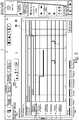
1 eine schematische Darstellung der erfindungsgemäßen Produktionsmaschine;2 eine Ausführungsform der Visualisierung einer Station auf der Visualisierungseinrichtung mit hervorgehobener geschwindigkeitsbestimmender Station gemäß der vorliegenden Erfindung;3 eine Ausführungsform der Visualisierung der Maschinenkomponenten einer Station auf der Visualisierungseinrichtung mit hervorgehobener geschwindigkeitsbestimmender Maschinenkomponente gemäß der vorliegenden Erfindung;4 eine erfindungsgemäße Ausführungsform gemäß3 mit zusätzlich angezeigten Schaltfeldern zur Eingabe von Zeitwerten;5 eine Ausführungsform des erfindungsgemäßen Verfahrens in seiner Darstellung als schematisches Ablaufdiagramm.
1 a schematic representation of the production machine according to the invention;2 an embodiment of the visualization of a station on the visualization device with highlighted speed-determining station according to the present invention;3 an embodiment of the visualization of the machine components of a station on the visualization device with highlighted speed-determining machine component according to the present invention;4th an embodiment of the invention according to3 with additionally displayed switch fields for entering time values;5 an embodiment of the method according to the invention in its representation as a schematic flow diagram.
AusführungsbeispieleEmbodiments
An dieser Stelle sei explizit darauf hingewiesen, dass Merkmale der vorstehend bzw. in den Ansprüchen und/oder Figuren beschriebenen Lösungen gegebenenfalls auch kombiniert werden können, um auch erläuterte Merkmale, Effekte und Vorteile entsprechend kumuliert umsetzen bzw. erzielen zu können.At this point it should be explicitly pointed out that features of the solutions described above or in the claims and / or figures can optionally also be combined in order to also be able to implement or achieve cumulatively explained features, effects and advantages.
Es versteht sich, dass es sich bei dem vorstehend erläuterten Ausführungsbeispiel lediglich um eine erste Ausgestaltung der vorliegenden Erfindung handelt. Insofern beschränkt sich die Ausgestaltung der Erfindung nicht auf dieses Ausführungsbeispiel.It goes without saying that the exemplary embodiment explained above is only a first embodiment of the present invention. In this respect, the configuration of the invention is not limited to this exemplary embodiment.
BezugszeichenlisteList of reference symbols
- 11
- Produktionsmaschine, beispielweise eine Thermoformmaschine oder eine BlasformmaschineProduction machine, for example a thermoforming machine or a blow molding machine
- 22
- Stationstation
- 33
- MaschinenkomponenteMachine component
- 44th
- MaschinensteuerungMachine control
- 55
- SteuerungsprogrammControl program
- 66th
- VisualisierungseinrichtungVisualization device
- 77th
- AblaufdiagrammFlow chart
- 88th
- hervorgehobene (weil geschwindigkeitsbestimmende) Stationhighlighted (because speed-determining) station
- 99
- hervorgehobene (weil geschwindigkeitsbestimmende) Maschinenkomponentehighlighted (because speed-determining) machine component
- 1010
- vertikale Linie zur Visualisierung einer Verknüpfung der geschwindigkeitsbestimmenden Station (hier Stapelung) mit einem darauffolgenden Prozessschritt (hier Vorschub)vertical line to visualize a link between the speed-determining station (here stacking) with a subsequent process step (here feed)
- 1111
- vertikaler Zeiger zur Visualisierung einer Freigabe als geschwindigkeitsbestimmender Schritt des Obertisches als Maschinenkomponente, wobei der Zeiger auf den dadurch freigegebenen nachfolgenden Prozessschritt hinweist (hier Vorschub)Vertical pointer to visualize a release as a speed-determining step of the upper table as a machine component, whereby the pointer points to the subsequent process step released as a result (here feed)
- 1212th
- ZeitphasenTime phases
- 1313
- Schaltfeld(er)Control panel (s)
- 1414th
- BenutzerhilfeUser help
- 1515th
- Separate Stations-VisualisierungsseiteSeparate station visualization page
- 1616
- Schaltfläche zum Wechsel zwischen einzelnen Stations-VisualisierungsseitenButton for switching between individual station visualization pages
- 100100
- Verfahren zur Prozesszeitoptimierung einer ProduktionsmaschineMethod for process time optimization of a production machine
- 110110
- Visualisierung eines Ablaufdiagramms zumindest einiger der Stationen mit Angabe der geschwindigkeitsbestimmenden Stationen und geschwindigkeitsbestimmenden Maschinenkomponenten nebst Visualisierung von Schaltfeldern für die Eingabe geänderter ZeitwerteVisualization of a flow chart of at least some of the stations with details of the speed-determining stations and speed-determining machine components as well as visualization of switching fields for entering changed time values
- 140140
- Benutzerseitige Eingabe eines oder mehrerer Zeitwerte in das Schaltfeld nebst Befehl zur Übernahme in das SteuerungsprogrammUser-side entry of one or more time values in the switch field together with the command for transfer to the control program
- 150150
- Anpassung des Produktionsprogramms auf Basis der variierten ZeitwerteAdjustment of the production program based on the varied time values
- 160160
- Erneutes (optional automatisiertes) Durchlaufen der Verfahrensschritte zur weitergehenden Optimierung der ProzesszeitRenewed (optionally automated) running through the process steps for further optimization of the process time
Claims (19)
Translated fromGermanPriority Applications (5)
| Application Number | Priority Date | Filing Date | Title |
|---|---|---|---|
| DE102019117097.4ADE102019117097A1 (en) | 2019-06-25 | 2019-06-25 | DEVICE AND METHOD FOR OPTIMIZING THE PROCESS TIME OF A PRODUCTION MACHINE |
| CN202080046433.4ACN114041093B (en) | 2019-06-25 | 2020-06-22 | Apparatus and method for optimizing process time of production machine |
| PCT/DE2020/000136WO2020259728A1 (en) | 2019-06-25 | 2020-06-22 | Device and method for optimising the process time of a production machine |
| EP20743058.8AEP3990993B8 (en) | 2019-06-25 | 2020-06-22 | Device and method for optimising the process time of a production machine |
| US17/621,488US20230221705A1 (en) | 2019-06-25 | 2020-06-22 | Device and method for optimising the process time of a production machine |
Applications Claiming Priority (1)
| Application Number | Priority Date | Filing Date | Title |
|---|---|---|---|
| DE102019117097.4ADE102019117097A1 (en) | 2019-06-25 | 2019-06-25 | DEVICE AND METHOD FOR OPTIMIZING THE PROCESS TIME OF A PRODUCTION MACHINE |
Publications (1)
| Publication Number | Publication Date |
|---|---|
| DE102019117097A1true DE102019117097A1 (en) | 2020-12-31 |
Family
ID=71728530
Family Applications (1)
| Application Number | Title | Priority Date | Filing Date |
|---|---|---|---|
| DE102019117097.4AWithdrawnDE102019117097A1 (en) | 2019-06-25 | 2019-06-25 | DEVICE AND METHOD FOR OPTIMIZING THE PROCESS TIME OF A PRODUCTION MACHINE |
Country Status (5)
| Country | Link |
|---|---|
| US (1) | US20230221705A1 (en) |
| EP (1) | EP3990993B8 (en) |
| CN (1) | CN114041093B (en) |
| DE (1) | DE102019117097A1 (en) |
| WO (1) | WO2020259728A1 (en) |
Families Citing this family (1)
| Publication number | Priority date | Publication date | Assignee | Title |
|---|---|---|---|---|
| DE102020126779A1 (en)* | 2020-10-13 | 2022-04-14 | Fritsch Bakery Technologies GmbH & Co. KG | Dough processing machine for processing products |
Citations (1)
| Publication number | Priority date | Publication date | Assignee | Title |
|---|---|---|---|---|
| DE112005001040T5 (en)* | 2004-05-04 | 2007-04-19 | Fisher-Rosemount Systems, Inc., Austin | Graphics integration into a process configuration and control environment |
Family Cites Families (25)
| Publication number | Priority date | Publication date | Assignee | Title |
|---|---|---|---|---|
| US5416900A (en)* | 1991-04-25 | 1995-05-16 | Lotus Development Corporation | Presentation manager |
| US5880960A (en)* | 1997-01-27 | 1999-03-09 | Taiwan Semiconductor Manufacturing Company, Ltd. | Method to improve WIP balance in a manufacturing line |
| JPH11235648A (en)* | 1998-02-17 | 1999-08-31 | Toshiba Corp | Manufacturing plan management device, manufacturing plan management method, and computer-readable recording medium storing manufacturing plan management program |
| US6446183B1 (en)* | 2000-02-15 | 2002-09-03 | International Business Machines Corporation | Systems and methods for persistent and robust memory management |
| US6519498B1 (en)* | 2000-03-10 | 2003-02-11 | Applied Materials, Inc. | Method and apparatus for managing scheduling in a multiple cluster tool |
| US6631305B2 (en)* | 2000-05-03 | 2003-10-07 | General Electric Company | Capability analysis of assembly line production |
| US6904329B1 (en)* | 2002-08-30 | 2005-06-07 | Advanced Micro Devices, Inc. | Method and apparatus for generating a multi-dimensional cost function |
| US6801819B1 (en)* | 2002-08-30 | 2004-10-05 | Advanced Micro Devices, Inc. | Method and apparatus for evaluating bids for scheduling a resource |
| DE10311027A1 (en)* | 2003-03-13 | 2004-09-30 | Siemens Ag | Testing and process simulation system for machine tool, comprising facility for representing measured data and simulation results on single screen |
| DE102005024915B4 (en)* | 2005-05-31 | 2016-09-15 | Advanced Micro Devices, Inc. | Method and system for advanced process control with plant-dependent machine constants |
| SE529599C2 (en)* | 2006-02-01 | 2007-10-02 | Tobii Technology Ab | Computer system has data processor that generates feedback data based on absolute position of user's gaze point with respect to display during initial phase, and based on image data during phase subsequent to initial phase |
| US7715936B2 (en)* | 2006-08-25 | 2010-05-11 | I-Factory Inc. | System and method for the production of goods or products |
| JP5130037B2 (en)* | 2007-12-27 | 2013-01-30 | 株式会社日立製作所 | Bottleneck device extraction method and bottleneck device extraction support device |
| EP2224384A1 (en)* | 2009-02-25 | 2010-09-01 | Siemens Aktiengesellschaft | Method and system for scheduling a manufacturing process |
| DE102011115904A1 (en)* | 2011-06-14 | 2012-12-20 | Böwe Systec Gmbh | Graphical user interface |
| CN104054032B (en)* | 2012-02-23 | 2016-09-07 | Abb研究有限公司 | For the method providing the navigational tool of user interface for industrial control system |
| EP2645191A1 (en)* | 2012-03-28 | 2013-10-02 | ABB Research Ltd. | A method for visualizing material flow of raw or semi-processed material in a process control system |
| EP3038442B1 (en)* | 2013-08-22 | 2021-08-18 | FUJI Corporation | Production optimization device for component mounting line |
| WO2015064214A1 (en)* | 2013-11-02 | 2015-05-07 | インターナショナル・ビジネス・マシーンズ・コーポレーション | Interactive test schedule adjustment method |
| CN107432119B (en)* | 2015-03-26 | 2020-02-14 | 株式会社富士 | Optimization device and optimization method for component mounting line |
| US10191792B2 (en)* | 2016-03-04 | 2019-01-29 | International Business Machines Corporation | Application abnormality detection |
| JP6604433B2 (en)* | 2016-04-26 | 2019-11-13 | 富士通株式会社 | Work support device, work support method, and work support program |
| US10692030B2 (en)* | 2016-06-21 | 2020-06-23 | Amazon Technologies, Inc. | Process visualization platform |
| CN110226139B (en)* | 2017-02-09 | 2022-05-27 | 株式会社富士 | Optimizing device for production line |
| JP6981113B2 (en)* | 2017-09-05 | 2021-12-15 | オムロン株式会社 | Information processing equipment and information processing method |
- 2019
- 2019-06-25DEDE102019117097.4Apatent/DE102019117097A1/ennot_activeWithdrawn
- 2020
- 2020-06-22EPEP20743058.8Apatent/EP3990993B8/enactiveActive
- 2020-06-22CNCN202080046433.4Apatent/CN114041093B/enactiveActive
- 2020-06-22USUS17/621,488patent/US20230221705A1/enactivePending
- 2020-06-22WOPCT/DE2020/000136patent/WO2020259728A1/ennot_activeCeased
Patent Citations (1)
| Publication number | Priority date | Publication date | Assignee | Title |
|---|---|---|---|---|
| DE112005001040T5 (en)* | 2004-05-04 | 2007-04-19 | Fisher-Rosemount Systems, Inc., Austin | Graphics integration into a process configuration and control environment |
Also Published As
| Publication number | Publication date |
|---|---|
| US20230221705A1 (en) | 2023-07-13 |
| EP3990993A1 (en) | 2022-05-04 |
| CN114041093B (en) | 2024-03-08 |
| EP3990993B8 (en) | 2024-09-04 |
| WO2020259728A1 (en) | 2020-12-30 |
| CN114041093A (en) | 2022-02-11 |
| EP3990993B1 (en) | 2024-07-31 |
Similar Documents
| Publication | Publication Date | Title |
|---|---|---|
| DE102012207916B3 (en) | Method and device for the automated configuration of a monitoring function of a machine tool | |
| EP1656245B1 (en) | Method and device for interactive control of a machine | |
| EP0573912B1 (en) | Method for controlling an injection moulding machine | |
| EP1902827B1 (en) | Controller for a blow moulding machine with several functional units | |
| DE60010609T2 (en) | Composite system of robot and machine | |
| WO2009105797A1 (en) | Configuration of machine processes | |
| EP3990995B1 (en) | Production machine comprising a control programme | |
| EP1889129A1 (en) | Method for the sequential programming of an injection molding cycle of an injection molding machine | |
| DE102019004458A1 (en) | NUMERIC CONTROL AND DATA EDITING PROCESS | |
| EP3990993B1 (en) | Device and method for optimising the process time of a production machine | |
| EP0801340B1 (en) | Method and device for controlling a machine tool, in particular an electro-erosion machine | |
| AT522653A1 (en) | Process for the representation and operation of means of production, especially for the plastics processing industry | |
| EP2735425B1 (en) | Operating unit for an injection moulding machine | |
| EP3714410A1 (en) | Method for viewing and selecting production means, in particular peripheral devices, for the injection molding industry, and an industrial facility | |
| DE102007014271A1 (en) | Technical system operating and controlling method, involves locating graphical surface on screen of input device, and developing machine model on empty sheet such that active control of model is produced by combining components of pallets | |
| DE102012004983A1 (en) | Method for graphic-based robot programming of multiaxial-robot comprising programming interface with graphical icons by device, involves pulling and dropping one or more icons on programming interface for executing desired movement | |
| DE102013208411A1 (en) | Operating procedure for a sewing machine for sewing workpieces | |
| WO1996012218A1 (en) | Process and device for controlling edm machines | |
| DE102004048039B4 (en) | Production plant for processing different batches with at least one workpiece each | |
| DE60117673T2 (en) | Method for adjusting operational measures in the production of hollow glassware | |
| DE19808679C1 (en) | Conversion of machine settings when transferring tools between incompletely compatible computer-controlled injection molding machines | |
| EP4495719A1 (en) | Method and engineering system for generating a user interface for an industrial automation assembly | |
| AT513368B1 (en) | Device and method for creating a web-based page for an operating device as a human-machine interface | |
| EP2463421A1 (en) | Design device for manufacturing knitted fabrics on a flat knitting machine with optimised duration | |
| WO2014146716A1 (en) | Engineering system of a process plant and/or production plant |
Legal Events
| Date | Code | Title | Description |
|---|---|---|---|
| R012 | Request for examination validly filed | ||
| R016 | Response to examination communication | ||
| R082 | Change of representative | Representative=s name:DTS PATENT- UND RECHTSANWAELTE SCHNEKENBUEHL U, DE Representative=s name:FARAGO PATENTANWALTSGESELLSCHAFT MBH, DE Representative=s name:DTS PATENT- UND RECHTSANWAELTE PARTMBB, DE | |
| R082 | Change of representative | Representative=s name:DTS PATENT- UND RECHTSANWAELTE SCHNEKENBUEHL U, DE Representative=s name:DTS PATENT- UND RECHTSANWAELTE PARTMBB, DE | |
| R119 | Application deemed withdrawn, or ip right lapsed, due to non-payment of renewal fee |