DE102019115639A1 - Nasal cannula with improved secured connection to a supply line - Google Patents
Nasal cannula with improved secured connection to a supply lineDownload PDFInfo
- Publication number
- DE102019115639A1 DE102019115639A1DE102019115639.4ADE102019115639ADE102019115639A1DE 102019115639 A1DE102019115639 A1DE 102019115639A1DE 102019115639 ADE102019115639 ADE 102019115639ADE 102019115639 A1DE102019115639 A1DE 102019115639A1
- Authority
- DE
- Germany
- Prior art keywords
- connection
- locking
- locking assembly
- therapy gas
- gas supply
- Prior art date
- Legal status (The legal status is an assumption and is not a legal conclusion. Google has not performed a legal analysis and makes no representation as to the accuracy of the status listed.)
- Withdrawn
Links
- 238000002560therapeutic procedureMethods0.000claimsabstractdescription117
- 239000011521glassSubstances0.000claimsabstractdescription55
- 230000015572biosynthetic processEffects0.000claimsdescription33
- 230000004888barrier functionEffects0.000claimsdescription13
- 239000012530fluidSubstances0.000claimsdescription4
- 238000013519translationMethods0.000claimsdescription2
- 239000007789gasSubstances0.000description72
- 239000000463materialSubstances0.000description17
- 210000002105tongueAnatomy0.000description14
- 230000001225therapeutic effectEffects0.000description10
- 230000008878couplingEffects0.000description7
- 238000010168coupling processMethods0.000description7
- 238000005859coupling reactionMethods0.000description7
- 238000006073displacement reactionMethods0.000description5
- 230000000295complement effectEffects0.000description3
- 230000001066destructive effectEffects0.000description3
- 230000000694effectsEffects0.000description3
- 239000007787solidSubstances0.000description3
- 230000009471actionEffects0.000description2
- 230000008859changeEffects0.000description2
- 210000000078clawAnatomy0.000description2
- 125000000524functional groupChemical group0.000description2
- 230000000149penetrating effectEffects0.000description2
- 238000007789sealingMethods0.000description2
- 239000000243solutionSubstances0.000description2
- BUHVIAUBTBOHAG-FOYDDCNASA-N(2r,3r,4s,5r)-2-[6-[[2-(3,5-dimethoxyphenyl)-2-(2-methylphenyl)ethyl]amino]purin-9-yl]-5-(hydroxymethyl)oxolane-3,4-diolChemical compoundCOC1=CC(OC)=CC(C(CNC=2C=3N=CN(C=3N=CN=2)[C@H]2[C@@H]([C@H](O)[C@@H](CO)O2)O)C=2C(=CC=CC=2)C)=C1BUHVIAUBTBOHAG-FOYDDCNASA-N0.000description1
- STPKWKPURVSAJF-LJEWAXOPSA-N(4r,5r)-5-[4-[[4-(1-aza-4-azoniabicyclo[2.2.2]octan-4-ylmethyl)phenyl]methoxy]phenyl]-3,3-dibutyl-7-(dimethylamino)-1,1-dioxo-4,5-dihydro-2h-1$l^{6}-benzothiepin-4-olChemical compoundO[C@H]1C(CCCC)(CCCC)CS(=O)(=O)C2=CC=C(N(C)C)C=C2[C@H]1C(C=C1)=CC=C1OCC(C=C1)=CC=C1C[N+]1(CC2)CCN2CC1STPKWKPURVSAJF-LJEWAXOPSA-N0.000description1
- 101100008046Caenorhabditis elegans cut-2 geneProteins0.000description1
- QVGXLLKOCUKJST-UHFFFAOYSA-Natomic oxygenChemical compound[O]QVGXLLKOCUKJST-UHFFFAOYSA-N0.000description1
- 238000005452bendingMethods0.000description1
- 230000006378damageEffects0.000description1
- 238000013461designMethods0.000description1
- 238000011161developmentMethods0.000description1
- 238000001746injection mouldingMethods0.000description1
- 230000003993interactionEffects0.000description1
- 230000013011matingEffects0.000description1
- 230000007246mechanismEffects0.000description1
- 239000001301oxygenSubstances0.000description1
- 229910052760oxygenInorganic materials0.000description1
- 229920001296polysiloxanePolymers0.000description1
- 230000036316preloadEffects0.000description1
- 230000002265preventionEffects0.000description1
- 230000000284resting effectEffects0.000description1
- 238000000926separation methodMethods0.000description1
- 238000012546transferMethods0.000description1
Images


Classifications
- A—HUMAN NECESSITIES
- A61—MEDICAL OR VETERINARY SCIENCE; HYGIENE
- A61M—DEVICES FOR INTRODUCING MEDIA INTO, OR ONTO, THE BODY; DEVICES FOR TRANSDUCING BODY MEDIA OR FOR TAKING MEDIA FROM THE BODY; DEVICES FOR PRODUCING OR ENDING SLEEP OR STUPOR
- A61M16/00—Devices for influencing the respiratory system of patients by gas treatment, e.g. ventilators; Tracheal tubes
- A61M16/06—Respiratory or anaesthetic masks
- A61M16/0666—Nasal cannulas or tubing
- A61M16/0672—Nasal cannula assemblies for oxygen therapy
- A—HUMAN NECESSITIES
- A61—MEDICAL OR VETERINARY SCIENCE; HYGIENE
- A61M—DEVICES FOR INTRODUCING MEDIA INTO, OR ONTO, THE BODY; DEVICES FOR TRANSDUCING BODY MEDIA OR FOR TAKING MEDIA FROM THE BODY; DEVICES FOR PRODUCING OR ENDING SLEEP OR STUPOR
- A61M16/00—Devices for influencing the respiratory system of patients by gas treatment, e.g. ventilators; Tracheal tubes
- A61M16/06—Respiratory or anaesthetic masks
- A61M16/0683—Holding devices therefor
- A—HUMAN NECESSITIES
- A61—MEDICAL OR VETERINARY SCIENCE; HYGIENE
- A61M—DEVICES FOR INTRODUCING MEDIA INTO, OR ONTO, THE BODY; DEVICES FOR TRANSDUCING BODY MEDIA OR FOR TAKING MEDIA FROM THE BODY; DEVICES FOR PRODUCING OR ENDING SLEEP OR STUPOR
- A61M16/00—Devices for influencing the respiratory system of patients by gas treatment, e.g. ventilators; Tracheal tubes
- A61M16/08—Bellows; Connecting tubes ; Water traps; Patient circuits
- A61M16/0816—Joints or connectors
- A—HUMAN NECESSITIES
- A61—MEDICAL OR VETERINARY SCIENCE; HYGIENE
- A61M—DEVICES FOR INTRODUCING MEDIA INTO, OR ONTO, THE BODY; DEVICES FOR TRANSDUCING BODY MEDIA OR FOR TAKING MEDIA FROM THE BODY; DEVICES FOR PRODUCING OR ENDING SLEEP OR STUPOR
- A61M16/00—Devices for influencing the respiratory system of patients by gas treatment, e.g. ventilators; Tracheal tubes
- A61M16/08—Bellows; Connecting tubes ; Water traps; Patient circuits
- A61M16/0875—Connecting tubes
- A—HUMAN NECESSITIES
- A61—MEDICAL OR VETERINARY SCIENCE; HYGIENE
- A61M—DEVICES FOR INTRODUCING MEDIA INTO, OR ONTO, THE BODY; DEVICES FOR TRANSDUCING BODY MEDIA OR FOR TAKING MEDIA FROM THE BODY; DEVICES FOR PRODUCING OR ENDING SLEEP OR STUPOR
- A61M2202/00—Special media to be introduced, removed or treated
- A61M2202/02—Gases
- A61M2202/0208—Oxygen
- A—HUMAN NECESSITIES
- A61—MEDICAL OR VETERINARY SCIENCE; HYGIENE
- A61M—DEVICES FOR INTRODUCING MEDIA INTO, OR ONTO, THE BODY; DEVICES FOR TRANSDUCING BODY MEDIA OR FOR TAKING MEDIA FROM THE BODY; DEVICES FOR PRODUCING OR ENDING SLEEP OR STUPOR
- A61M2205/00—General characteristics of the apparatus
- A61M2205/02—General characteristics of the apparatus characterised by a particular materials
- A61M2205/0216—Materials providing elastic properties, e.g. for facilitating deformation and avoid breaking
- A—HUMAN NECESSITIES
- A61—MEDICAL OR VETERINARY SCIENCE; HYGIENE
- A61M—DEVICES FOR INTRODUCING MEDIA INTO, OR ONTO, THE BODY; DEVICES FOR TRANSDUCING BODY MEDIA OR FOR TAKING MEDIA FROM THE BODY; DEVICES FOR PRODUCING OR ENDING SLEEP OR STUPOR
- A61M2205/00—General characteristics of the apparatus
- A61M2205/58—Means for facilitating use, e.g. by people with impaired vision
- A61M2205/581—Means for facilitating use, e.g. by people with impaired vision by audible feedback
- A—HUMAN NECESSITIES
- A61—MEDICAL OR VETERINARY SCIENCE; HYGIENE
- A61M—DEVICES FOR INTRODUCING MEDIA INTO, OR ONTO, THE BODY; DEVICES FOR TRANSDUCING BODY MEDIA OR FOR TAKING MEDIA FROM THE BODY; DEVICES FOR PRODUCING OR ENDING SLEEP OR STUPOR
- A61M2205/00—General characteristics of the apparatus
- A61M2205/58—Means for facilitating use, e.g. by people with impaired vision
- A61M2205/582—Means for facilitating use, e.g. by people with impaired vision by tactile feedback
Landscapes
- Health & Medical Sciences (AREA)
- Pulmonology (AREA)
- Emergency Medicine (AREA)
- Biomedical Technology (AREA)
- Engineering & Computer Science (AREA)
- Anesthesiology (AREA)
- Heart & Thoracic Surgery (AREA)
- Hematology (AREA)
- Life Sciences & Earth Sciences (AREA)
- Animal Behavior & Ethology (AREA)
- General Health & Medical Sciences (AREA)
- Public Health (AREA)
- Veterinary Medicine (AREA)
- Otolaryngology (AREA)
- Infusion, Injection, And Reservoir Apparatuses (AREA)
Abstract
Translated fromGermanDescription
Translated fromGermanDie vorliegende Erfindung betrifft ein Patiententherapiegasversorgungssystem, umfassend eine Nasenbrille zur nasalen Versorgung eines Patienten mit Therapiegas, wobei die Nasenbrille umfasst: einen Brillenanschluss, und eine Therapiegasabgabeöffnung zur Abgabe des Therapiegases an den Patienten, wobei die Nasenbrille eine Fluidleitung zwischen der Therapiegasabgabeöffnung und dem Brillenanschluss definiert; eine Therapiegaszufuhrleitung zur Zuführung von Therapiegas zur Nasenbrille, wobei die Therapiegaszufuhrleitung einen Leitungsanschluss aufweist, welcher dafür eingerichtet ist, in einem Verbindungsbereich mit dem Brillenanschluss eine lösbare Therapiegas-führende Verbindung auszubilden, wobei sich der Brillenanschluss und der Leitungsanschluss bei hergestellter Therapiegas-führender Verbindung längs eines durch den Verbindungsbereich verlaufenden Abschnitt eines Strömungspfads überlappen; und eine Arretierungsbaugruppe, wobei die Arretierungsbaugruppe zwischen einer Arretierungsstellung und einer Freigabestellung bewegbar ist, wobei eine zur Lösung der Verbindung zwischen dem Brillenanschluss und dem Leitungsanschluss notwendige Kraft dann, wenn die Arretierungsbaugruppe sich in der Arretierungsstellung befindet, betragsmäßig größer ist als dann, wenn sich die Arretierungsbaugruppe in der Freigabestellung befindet.The present invention relates to a patient therapy gas supply system, comprising a nasal cannula for nasally supplying a patient with therapy gas, the nasal cannula comprising: a spectacle connector and a therapy gas delivery opening for delivering the therapy gas to the patient, the nasal cannula defining a fluid line between the therapy gas delivery opening and the spectacle connector; a therapy gas supply line for supplying therapy gas to the nasal cannula, wherein the therapy gas supply line has a line connection which is set up to form a detachable therapy gas-carrying connection in a connection area with the goggles connection, the goggles connection and the line connection being along one when the therapy gas-carrying connection is established overlap a portion of a flow path extending through the connection region; and a locking assembly, wherein the locking assembly is movable between a locking position and a release position, wherein a force necessary to release the connection between the eyeglass connector and the line connector when the locking assembly is in the locking position is greater in magnitude than when the Locking assembly is in the release position.
Ein Strömungspfad, der stets ein virtueller Strömungspfad ist, kann in dieser Anmeldung durch den Pfad definiert sein, welcher die geometrischen Schwerpunkte der Querschnitte der Therapiegas-führenden Bereiche, z. B. dem Innenvolumen eines Schlauchabschnitts oder/und der Nasenbrille, des Patiententherapiegasversorgungssystems längs der Strömungsbewegung verbindet. Insbesondere kann der Strömungspfad im Zweifelsfall als die Therapiegas-führenden Fluidleitungen des Patiententherapiegasversorgungssystems zentral durchsetzend gedacht sein.A flow path, which is always a virtual flow path, can be defined in this application by the path which defines the geometric focal points of the cross-sections of the therapeutic gas-carrying areas, e.g. B. the inner volume of a tube section and / or the nasal cannula, the patient therapy gas supply system connects along the flow movement. In particular, in the case of doubt, the flow path can be thought of as centrally penetrating the therapy gas-carrying fluid lines of the patient therapy gas supply system.
Patiententherapiegasversorgungssysteme werden in dieser Anmeldung in einem Zustand beschrieben, in welchem die Therapiegas-führende Verbindung ausgebildet ist, sofern nichts anderes explizit beschrieben wird.Patient therapy gas supply systems are described in this application in a state in which the therapy gas-conducting connection is formed, unless otherwise explicitly described.
Ferner wird zur Beschreibung von Richtungen der Strömungspfad für eine Strömungspfadrichtung als Referenz herangezogen, wobei eine Strömungspfadrichtung parallel oder antiparallel zu einem eine Tangente des Strömungspfads beschreibenden Richtungsvektor verläuft. Unter einer Radialrichtung oder einer radialen Richtung, welche sich auf den Strömungspfad bezieht ist eine Richtung zu verstehen, die senkrecht zu einer Tangente des Strömungspfads in einem Punkt des Strömungspfads verläuft und von diesem Punkt weg zeigt. Eine Umfangsrichtung bezeichnet eine den Strömungspfad oder eine Achse umlaufende Richtung. Dies führt bei einem gekrümmt verlaufenden Strömungspfad zur Änderung der Strömungspfadrichtung, der Radialrichtung und der Umfangsrichtung in einem bezüglich des Patiententherapiegasversorgungssystems ortsfesten kartesischen Koordinatensystem.Furthermore, to describe directions, the flow path for a flow path direction is used as a reference, a flow path direction running parallel or anti-parallel to a direction vector describing a tangent of the flow path. A radial direction or a radial direction which relates to the flow path is to be understood as a direction which runs perpendicular to a tangent of the flow path at a point on the flow path and points away from this point. A circumferential direction denotes a direction surrounding the flow path or an axis. In the case of a curved flow path, this leads to a change in the flow path direction, the radial direction and the circumferential direction in a Cartesian coordinate system which is stationary with respect to the patient therapy gas supply system.
Ein oben beschriebenes Patiententherapiegasversorgungssystem ist beispielsweise aus der Druckschrift
Es ist daher die Aufgabe der vorliegenden Erfindung, ein Patiententherapiegasversorgungssystem bereitzustellen, bei welchem eine lösbare und sichere Therapiegas-führende Verbindung ausgebildet werden kann.It is therefore the object of the present invention to provide a patient therapy gas supply system in which a releasable and safe therapy gas-carrying connection can be formed.
Diese Aufgabe wird erfindungsgemäß durch ein Patiententherapiegasversorgungssystem der eingangs genannten Art gelöst, bei welchem die Arretierungsbaugruppe bei hergestellter Therapiegas-führender Verbindung relativ zum Brillenanschluss und zum Leitungsanschluss zwischen der Arretierungsstellung und der Freigabestellung derart verlagerbar ist, dass sie in der Arretierungsstellung einen größeren Überlapp mit dem Verbindungsbereich aufweist als in der Freigabestellung. Durch den größeren Überlapp der Arretierungsbaugruppe mit dem Verbindungsbereich wird eine Bewegungsfreiheit des Brillenanschlusses und/oder des Leitungsanschlusses in der Arretierungsstellung im Verbindungsbereich stärker eingeschränkt als in der Freigabestellung, sodass einer Verformung des Brillenanschlusses und/oder des Leitungsanschlusses, welche zur Lösung der Therapiegas-führender Verbindung führen kann, entgegengewirkt wird, sodass die Sicherheit der Therapiegas-führender Verbindung verstärkt wird.According to the invention, this object is achieved by a patient therapy gas supply system of the type mentioned at the outset, in which the locking assembly can be displaced between the locking position and the release position relative to the glasses connection and the line connection when the connection carrying therapy gas is established, so that in the locking position it overlaps the connection area more than in the release position. Due to the greater overlap of the locking assembly with the connection area, freedom of movement of the glasses connection and / or the line connection is more restricted in the locking position in the connection area than in the release position, so that a deformation of the glasses connection and / or the line connection, which leads to resolution the therapy gas-conducting connection is counteracted, so that the safety of the therapy gas-conducting connection is increased.
Die Arretierungsbaugruppe liegt vorzugsweise bezogen auf den Strömungspfad in Radialrichtung weiter außen als der Brillenanschluss und der Leitungsanschluss. Der Überlapp der Arretierungsbaugruppe mit dem Verbindungsbereich dient dann für den Benutzer als Indikator für das Vorliegen oder Nicht-Vorliegen der Arretierungsstellung, wodurch die Häufigkeit der Fehleinschätzungen, ob die Arretierungsbaugruppe sich in der Arretierungsstellung befindet, reduziert wird, was wiederum eine Trennung der Therapiegas-führenden Verbindung vereinfacht. Ferner erlaubt der Wechsel zwischen der Arretierungsstellung und der Freigabestellung durch eine Verlagerung der Arretierungsbaugruppe dem Benutzer einfach zwischen beiden Stellungen zu wechseln. Befindet sich die Arretierungsbaugruppe in der Arretierungsstellung, so wird aufgrund der beschriebenen zur Lösung der Therapiegas-führenden Verbindung notwendigen Kräfte eine besonders sichere Therapiegas-führende Verbindung ausgebildet.The locking assembly is preferably located farther out in the radial direction in relation to the flow path than the glasses connection and the line connection. The overlap of the locking assembly with the connection area then serves as an indicator for the user of the presence or absence of the locking position, which reduces the frequency of misjudgments as to whether the locking assembly is in the locking position, which in turn results in a separation of the therapeutic gas-carrying Connection simplified. Furthermore, the change between the locking position and the release position allows the user to easily switch between the two positions by moving the locking assembly. If the locking assembly is in the locking position, a particularly safe therapy gas-carrying connection is formed on the basis of the forces described to release the connection that carries the therapy gas.
Der Verbindungsbereich kann sich in Strömungspfadrichtung über den durch Überlappung von Brillenanschluss und Leitungsanschluss definierten Bereich hinaus erstrecken. Bevorzugt ist der Verbindungsbereich nur jener Bereich, in welchem sich Brillenanschluss und Leitungsanschluss über einen gemeinsamen Strömungspfadabschnitt erstrecken, also überlappen.The connection area can extend in the flow path direction beyond the area defined by the overlap of the glasses connection and the line connection. The connection area is preferably only that area in which the glasses connection and line connection extend over a common flow path section, that is to say overlap.
Zur Bildung einer möglichst dichten Therapiegas-führenden Verbindung weisen sowohl der Leitungsanschluss als auch der Brillenanschluss jeweils geschlossen um den Strömungspfad umlaufende Anschlussabschnitte auf. Dies gilt insbesondere für diejenigen Verbindungsabschnitte von Leitungsanschluss und Brillenanschluss, welche überlappend die Therapiegas-führende Verbindung bilden.To form a connection that conducts therapy gas as tightly as possible, both the line connection and the goggle connection each have connection sections that encircle the flow path. This applies in particular to those connecting sections of the line connection and the eyeglass connection which overlap and form the connection that carries the therapy gas.
Zur Erleichterung der Herstellung einer dauerhaft dichten Therapiegas-führenden Verbindung ist bevorzugt ein Anschluss aus Leitungsanschluss und Brillenanschluss als Verformungsanschluss wenigstens im Verbindungsabschnitt mit geringerer Steifigkeit gegen eine Aufweitung in radialer Richtung ausgebildet als der jeweils andere Anschluss. Der jeweils andere Anschluss weist folglich als Stützanschluss wenigstens in seinem Verbindungsabschnitt eine höhere Steifigkeit gegen eine Verformung orthogonal zum Strömungspfad auf.To make it easier to establish a permanently tight connection carrying therapy gas, a connection comprising a line connection and a goggle connection is preferably designed as a deformation connection at least in the connection section with less rigidity against expansion in the radial direction than the respective other connection. The respective other connection consequently has, as a support connection, at least in its connection section a higher rigidity against deformation orthogonal to the flow path.
Vorzugsweise werden die unterschiedlichen Steifigkeiten durch die Verwendung von Materialien mit unterschiedlichen Elastizitätsmodulen für den Brillenanschluss und den Leitungsanschluss erreicht. Zur Herstellung der überlappenden Verbindung kann der Verformungsanschluss unter radialer Aufweitung gegen seine Materialelastizität über den Stützanschluss geschoben oder gezogen werden. Unter der durch seine Aufweitungsverformung bewirkten Vorspannung zurück in seine entspannte Gestalt liegt dann der Verformungsanschluss dichtend am Stützanschluss an.The different stiffnesses are preferably achieved through the use of materials with different elastic moduli for the glasses connection and the line connection. To produce the overlapping connection, the deformation connection can be pushed or pulled over the support connection with radial expansion against its material elasticity. Under the prestress caused by its expansion deformation back into its relaxed shape, the deformation connection then lies against the support connection in a sealing manner.
Da die Arretierungsbaugruppe zur erleichterten Betätigung bevorzugt radial außerhalb von Leitungsanschluss und Brillenanschluss angeordnet ist, kann die derart radial außen angeordnete Arretierungsbaugruppe auf den ihr radial näher gelegenen Verformungsanschluss zusätzlich vorteilhaft die Dichtungswirkung oder/und die Verbindungsfestigkeit zwischen Leitungsanschluss und Brillenanschluss im Verbindungsbereich erhöhend einwirken, etwa durch mechanische Krafteinwirkung auf die so für die Arretierungsbaugruppe unmittelbar zugänglichen Verformungsanschluss.Since the locking assembly is preferably arranged radially outside of the line connection and the eyeglass connector for easier actuation, the so radially outwardly disposed locking assembly can also advantageously increase the sealing effect and / or the connection strength between the line connector and the eyeglass connector in the connection area on the deformation connector located radially closer to it, for example by mechanical force acting on the deformation connection that is directly accessible to the locking assembly.
Da die Nasenbrille nahezu dauerhaft während einer Therapiegasversorgung mit der Haut des Patienten in Kontakt ist oder gelangen kann, ist bevorzugt der Brillenanschluss der oben genannte Verformungsanschluss.Since the nasal cannula is or can come into contact with the patient's skin almost permanently during a therapy gas supply, the eyeglass connector is preferably the aforementioned deformation connector.
Es sei an dieser Stelle klargestellt, dass zur Ausbildung der lösbaren Therapiegas-führenden Verbindung ein Reibschluss und/oder ein Formschluss und/oder ein Stoffschluss beiträgt bzw. ist.It should be made clear at this point that a friction fit and / or a form fit and / or a material fit contributes or is to the formation of the detachable therapy gas-carrying connection.
Um Kräfte möglichst großflächig auf den Verbindungsbereich zu übertragen und somit zur sicheren Ausbildung der Therapiegas-führenden Verbindung beizutragen, umgibt die Arretierungsbaugruppe den Strömungspfad zumindest abschnittsweise in einer Umfangsrichtung, bevorzugt vollständig in der Umfangsrichtung.In order to transfer forces to the connection area over the largest possible area and thus contribute to the secure formation of the therapy gas-carrying connection, the locking assembly surrounds the flow path at least in sections in a circumferential direction, preferably completely in the circumferential direction.
In einer bevorzugten Ausführungsform ist die Arretierungsbaugruppe separat von (d. h. nicht einstückig mit) dem Brillenanschluss und dem Leitungsanschluss ausgebildet. Hierdurch kann das Material oder die Materialien der Arretierungsbaugruppe unabhängig von den Materialien des Brillenanschlusses und des Leitungsanschlusses, ausgewählt werden. Um einen bestimmungsbemäßen Betrieb des Patiententherapiegasversorgungssystems sicherzustellen, ist die Arretierungsbaugruppe in mindestens einer, vorzugsweise in beiden Stellungen aus Arretierungsstellung und Freigabestellung, verliersicher an dem Brillenanschluss oder dem Leitungsanschluss angebracht.In a preferred embodiment, the locking assembly is separate from (i.e., not integral with) the eyeglass connector and the conduit connector. In this way, the material or the materials of the locking assembly can be selected independently of the materials of the glasses connection and the line connection. In order to ensure proper operation of the patient therapy gas supply system, the locking assembly is attached to the glasses connector or the line connector in at least one, preferably in both positions of the locking position and the release position.
In einer besonders bevorzugten Ausführungsform spannt die Arretierungsbaugruppe, dann, wenn die Arretierungsbaugruppe sich in der Arretierungsstellung befindet, zumindest abschnittsweise einen Anschluss aus dem Brillenanschluss und dem Leitungsanschluss in Richtung des anderen Anschlusses aus dem Brillenanschluss und dem Leitungsanschluss stärker vor, als dann, wenn die Arretierungsbaugruppe sich in der Freigabestellung befindet. Hierdurch kann in der Arretierungsstellung im Überlappbereich, insbesondere auch auf Grund des größeren Überlapps der Arretierungsbaugruppe mit dem Verbindungsbereich in der Arretierungsstellung der Arretierungsbaugruppe verglichen mit dem Zustand der Arretierungsbaugruppe in der Freigabestellung, der zwischen zwei einander anliegenden Flächen des Brillenanschlusses und des Leitungsanschlusses eine betragsmäßig größere Kraft wirken als dann, wenn die Arretierungsbaugruppe sich in der Freigabestellung befindet. Eine hieraus resultierende Reibungskraft zwischen diesen beiden Flächen oder eine hieraus resultierende, einer Verformung eines Anschlusses aus Brillenanschluss oder Leitungsanschluss entgegenwirkende Kraft muss beim Lösen der Therapiegas-führenden Verbindung überwunden werden, was auf eine einfache Art und Weise die zur Lösung der Verbindung zwischen dem Brillenanschluss und dem Leitungsanschluss notwendige Kraft, verglichen mit dem Zustand, in dem sich die Arretierungsbaugruppe in der Freigabestellung befindet, erhöht.In a particularly preferred embodiment, the locking assembly tensions, when the locking assembly is in the locking position, at least in sections a connection from the glasses connection and the line connection in the direction of the other connection from the glasses connection and the line connection in front of it more than when the locking assembly is in the release position. As a result, in the locking position in the overlap area, in particular also due to the larger overlap of the locking assembly with the connection area in the locking position of the locking assembly, compared to the state of the locking assembly in the release position, the force between two adjacent surfaces of the glasses connector and the line connector has a greater amount of force act as if the locking assembly is in the release position. A frictional force resulting therefrom between these two surfaces or a force resulting therefrom that counteracts deformation of a connection made up of a glasses connection or line connection must be overcome when the connection between the glasses connection and the therapy gas is released, which in a simple manner facilitates the release of the connection between the glasses connection and the force necessary for the line connection, compared with the state in which the locking assembly is in the release position, increased.
Die Arretierungsbaugruppe umfasst einen Arretierungsabschnitt, welcher dann, wenn die Arretierungsbaugruppe sich in der Arretierungsstellung befindet, mit dem Verbindungsbereich überlappt. Der Arretierungsabschnitt kann die Arretierungsbaugruppe sein. Es wird jedoch bevorzugt dass die Arretierungsbaugruppe zusätzlich zum Arretierungsabschnitt einen Trageabschnitt umfasst, welcher dann, wenn die Arretierungsbaugruppe sich in der Arretierungsstellung befindet, mit dem Verbindungsbereich nicht überlappt. Vorzugsweise sind der Arretierungsabschnitt und der Trageabschnitt einstückig ausgebildet.The locking assembly comprises a locking section which, when the locking assembly is in the locking position, overlaps with the connection area. The locking portion can be the locking assembly. However, it is preferred that the locking assembly comprises, in addition to the locking section, a carrying section which, when the locking assembly is in the locking position, does not overlap with the connection area. The locking section and the carrying section are preferably formed in one piece.
Der Arretierungsabschnitt kann eine Mehrzahl von um eine den Verbindungsbereich durchdringende Achse herum angeordneten Teilabschnitten umfassten, welche in Umfangsrichtung um die Achse herum voneinander beabstandet und mit vorzugsweise gleichem Zwischenwinkel zwischen benachbarten Teilabschnitten um die Achse herum angeordnet sind. Die Achse fällt vorzugsweise mit dem Strömungspfad oder einer seiner Tangenten zusammen oder ist zumindest parallel zu einer dieser Tangenten ausgebildet. Hierdurch kann das Gewicht der Arretierungsbaugruppe reduziert werden. Es wird jedoch bevorzugt, dass der Arretierungsabschnitt in der Umfangsrichtung durchgehend ausgebildet ist.The locking section can comprise a plurality of subsections which are arranged around an axis penetrating the connecting area and which are spaced from one another in the circumferential direction around the axis and are arranged with preferably the same intermediate angle between adjacent subsections around the axis. The axis preferably coincides with the flow path or one of its tangents or is at least formed parallel to one of these tangents. This can reduce the weight of the locking assembly. However, it is preferable that the locking portion is formed continuously in the circumferential direction.
Der Arretierungsabschnitt kann ein zumindest in einer Ansicht U-förmiges Bauteil, und/oder ein teilweise oder vollständig geschlossenes reversibel verformbares Band und/oder ein im Wesentlichen starres Ringelement umfassen, sodass ein an die Randbedingungen wie Flexibilität des Brillenabschnitts und/oder des Leitungsabschnitts, räumliche Beschränkungen für die Bewegung des Arretierungsabschnitts usw. angepasster Arretierungsabschnitt bereitgestellt werden kann.The locking section can comprise a component that is U-shaped, at least in one view, and / or a partially or completely closed reversibly deformable band and / or an essentially rigid ring element, so that a spatial one to the boundary conditions such as flexibility of the spectacle section and / or the line section Restrictions on the movement of the locking portion, etc. adapted locking portion can be provided.
Um zur Ausbildung einer sicheren und sicher zu handhabenden Therapiegas-führenden Verbindung beizutragen, kann das Patiententherapiegasversorgungssystem ferner wenigstens eine Formschlussanordnung umfassen, welche eine an dem Leitungsanschluss ausgebildete Formschlussformation und eine an dem Brillenanschluss ausgebildete Formschlussgegenformation aufweist, wobei die Formschlussformation durch Ausbilden eines Formschlusses zwischen der Formschlussformation und der Formschlussgegenformation zur Ausbildung der lösbaren Therapiegas-führenden Verbindung wenigstens beiträgt. Hierdurch kann, im Gegensatz zum Vorliegen einer alleine auf einem Reibschluss beruhenden Therapiegas-führenden Verbindung, ein Verbindungstyp bereitgestellt werden, welcher dem Benutzer ein haptisches und/oder akustisches Feedback beim Ausbilden oder Lösen des Formschlusses bereitstellt, wenn beispielsweise die Formschlussformation mit der Formschlussgegenformation zusammenwirkt oder von dieser gelöst wird, sodass der Benutzer mit erhöhter Sicherheit feststellen kann, ob eine Therapiegas-führende Verbindung ausgebildet oder getrennt ist. Die Formschlussanordnung ist vorzugsweise im Verbindungsbereich ausgebildet.In order to contribute to the formation of a safe and safe-to-handle therapy gas-carrying connection, the patient therapy gas supply system can further comprise at least one form-fit arrangement which has a form-fit formation formed on the line connection and a form-fit counter-formation formed on the glasses connection, the form-fit formation being formed by forming a form-fit between the form-fit formation and the interlocking counter-formation at least contributes to the formation of the detachable therapy gas-carrying connection. In this way, in contrast to the presence of a therapy gas-carrying connection based solely on a frictional connection, a connection type can be provided which provides the user with haptic and / or acoustic feedback when the form fit is formed or released, if for example the form fit formation interacts with the form fit counterformation is released from this, so that the user can determine with increased security whether a therapy gas-carrying connection is established or disconnected. The form-fit arrangement is preferably formed in the connection area.
In der Freigabestellung der Arretierungsbaugruppe liegt vorzugsweise kein Überlapp der Arretierungsbaugruppe und/oder des Arretierungsabschnitts mit dem Verbindungsbereich und/oder der Formschlussanordnung vor.In the release position of the locking assembly, there is preferably no overlap of the locking assembly and / or the locking section with the connection area and / or the form-fitting arrangement.
Um die Therapiegas-führende Verbindung stärker gegen ein ungewolltes Lösen zu sichern, kann die Formschlussanordnung den Strömungspfad zumindest teilweise, bevorzugt vollständig umschließen.In order to secure the therapy gas-conducting connection more strongly against unintentional loosening, the form-fit arrangement can at least partially, preferably completely enclose the flow path.
Ein Paar aus einer Formschlussformation und einer Formschlussgegenformation, welche zumindest Teil der Formschlussanordnung sind oder diese ausbilden, kann ein Paar aus einer Nut und einer Feder, und/oder ein Paar aus einem Vorsprung und einer Vertiefung, und/oder einem Paar aus einer Kralle und einem Rand, welcher von der Kralle hintergriffen wird, und/oder ein Paar von ineinandergreifenden Verzahnungen, und/oder ein Paar aus einer Sperrklinke und einer mit Rückhaltezähnen versehenen Fläche, oder ein ähnliches Paar sein.A pair of a form-fit formation and a form-fit counter-formation, which are at least part of the form-fit arrangement or form this, can be a pair made up of a groove and a tongue, and / or a pair made up of a projection and a depression, and / or a pair made up of a claw and a an edge, which is engaged from behind by the claw, and / or a pair of intermeshing teeth, and / or a pair of a pawl and a surface provided with retaining teeth, or a similar pair.
Es ist bevorzugt, dass die Formschlussanordnung derart ausgebildet ist, dass dann, wenn die Arretierungsbaugruppe sich in der Freigabestellung befindet, zur Lösung des Formschlusses eine Versatzbewegung eines Versatzabschnitts der Formschlussformation oder der Formschlussgegenformation entlang eines Versatzpfades beiträgt. Es ist möglich, dass die Versatzbewegung des Versatzabschnitts mit einer Verformung des Versatzabschnitts oder seiner Umgebung einhergeht, was eine Versatzverformung definiert. Unter einer Behinderung der Versatzbewegung wird jede betragsmäßige Erhöhung einer zur Ausführung der Versatzbewegung benötigten Kraft verstanden, verglichen mit einer Ausführung der Versatzbewegung ohne die die Behinderung begründenden Umstände oder Merkmale. Eine zumindest teilweise Verhinderung der Versatzbewegung ist ein Spezialfall einer größtmöglichen Behinderung der Versatzbewegung. Wegen der erleichterten Verformbarkeit ist der Versatzabschnitt bevorzugt am Verformungsanschluss ausgebildet.It is preferred that the form-fitting arrangement is designed such that when the locking assembly is in the release position is located, contributes to the solution of the form fit an offset movement of an offset section of the form fit formation or the form fit mating formation along an offset path. It is possible that the offset movement of the offset section is accompanied by a deformation of the offset section or its surroundings, which defines an offset deformation. A hindrance to the offset movement is understood to mean any increase in the amount of a force required to carry out the offset movement, compared with an execution of the offset movement without the circumstances or features justifying the hindrance. An at least partial prevention of the offset movement is a special case of the greatest possible hindrance to the offset movement. Because of the easier deformability, the offset section is preferably formed on the deformation connection.
In einer bevorzugten Ausführungsform verläuft mindestens eine Formation aus der Formschlussformation und der Formschlussgegenformation zumindest abschnittsweise nicht parallel zu einer Normalebene des Strömungspfads, welche die eine Formation aus der Formschlussformation und der Formschlussgegenformation schneidet. Dies erlaubt, dass nur eine, oder eine vorbestimmte Mehrzahl an vorbestimmten Relativpositionen zwischen dem Brillenanschluss und dem Leitungsanschluss bei ausgebildeter Therapiegas-führenden Verbindung eingenommen werden kann und somit das Patiententherapiegasversorgungssystem einfach über einen so ausgebildeten Indexmechanismus eine oder eine Mehrzahl an vorbestimmten für den Patienten bequemen Anordnungen einnehmen kann.In a preferred embodiment, at least one formation from the form-fit formation and the form-fit counter-formation does not run, at least in sections, parallel to a normal plane of the flow path which intersects the one formation from the form-fit formation and the form-fit counter-formation. This allows only one or a predetermined plurality of predetermined relative positions between the glasses connector and the line connector when the therapy gas-carrying connection is established, and thus the patient therapy gas supply system can easily have one or a plurality of predetermined arrangements that are convenient for the patient via an index mechanism designed in this way can take.
In einer besonders bevorzugten Ausführungsform umfasst das Patiententherapiegasversorgungsystem zur Sicherung der Therapiegas-führenden Verbindung ferner eine Stellungssicherungsvorrichtung, wobei die Arretierungsbaugruppe in der Arretierungsstellung durch eine Stellungssicherungsvorrichtung gegen eine Bewegung in Richtung der Freigabestellung sicherbar ist. Als Sicherung gilt jede Behinderung einer Bewegung der Arretierungsbaugruppe aus der Arretierungsstellung in Richtung zur Freigabestellung hin. Für die Behinderung der genannten Bewegung der Arretierungsbaugruppe gilt das oben zur Behinderung der Versatzbewegung Gesagte entsprechend. Dabei soll zugelassen sein, dass die Arretierungsbaugruppe in der Arretierungsstellung ein Bewegungsspiel aufweisen darf, wenngleich eine spielfreie Sicherung bevorzugt ist.In a particularly preferred embodiment, the patient therapy gas supply system for securing the therapy gas-carrying connection further comprises a position securing device, wherein the locking assembly can be secured in the locked position by a position securing device against movement in the direction of the release position. Any hindrance to a movement of the locking assembly out of the locking position in the direction of the release position is considered a safeguard. For the obstruction of the mentioned movement of the locking assembly, what has been said above regarding the obstruction of the offset movement applies accordingly. It should be allowed that the locking assembly may have a play in the locking position, although backlash-free securing is preferred.
Die Stellungssicherungsvorrichtung kann gemäß einer vorteilhaften Weiterbildung zwischen einer Gesichert-Stellung und einer Entsichert-Stellung bewegbar sein. Dabei ist dann, wenn sich die Arretierungsbaugruppe in der Arretierungsstellung befindet und die Stellungssicherungsvorrichtung sich in der Gesichert-Stellung befindet unter Mitwirkung der Stellungssicherungsvorrichtung bevorzugt eine körperliche Barriere ausgebildet, die eine Bewegung der Arretierungsbaugruppe von der Arretierungsstellung in die Freigabestellung behindert. Außerdem ist dann, wenn die Stellungssicherungsvorrichtung sich in der Entsichert-Stellung befindet, die unter Mitwirkung der Stellungssicherungsvorrichtung ausgebildete körperliche Barriere die Bewegung der Arretierungsbaugruppe von der Arretierungsstellung in die Freigabestellung weniger stark behindert als dann, wenn die Arretierungsbaugruppe sich in der Arretierungsstellung befindet und die Stellungssicherungsvorrichtung sich in der Gesichert-Stellung befindet. Eine derartige Stellungssicherungsvorrichtung in Kombination mit der Arretierungsbaugruppe reduziert die Wahrscheinlichkeit eines ungewollten Lösens der Therapiegas-führenden Verbindung stärker, als ein Patiententherapiegasversorgungssystem nur mit einer Arretierungsbaugruppe, da die Stellungssicherungsvorrichtung in der Gesichert-Stellung aufgrund der oben beschriebenen Behinderung die Wahrscheinlichkeit reduziert, dass die Arretierungsbaugruppe ungewollt von der Arretierungsstellung in die Freigabestellung bewegt wird.According to an advantageous development, the position securing device can be movable between a secured position and an unlocked position. In this case, when the locking assembly is in the locking position and the position securing device is in the secured position, with the assistance of the position securing device, a physical barrier is preferably formed which prevents the locking assembly from moving from the locking position into the release position. In addition, when the position assurance device is in the unlocked position, the physical barrier formed with the assistance of the position assurance device, the movement of the locking assembly from the locking position into the release position is less hindered than when the locking assembly is in the locking position and the position assurance device is in the secured position. Such a position securing device in combination with the locking assembly reduces the likelihood of unintentional loosening of the therapy gas-carrying connection more than a patient therapy gas supply system with only one locking assembly, since the position securing device in the locked position reduces the probability that the locking assembly will be unintentionally due to the above-described obstruction is moved from the locking position to the release position.
Zur einfachen, bevorzugt selbsttätigen Sicherung der Arretierungsbaugruppe in der Arretierungsstellung kann die Stellungssicherungsvorrichtung eine Rastanordnung mit einem Rastvorsprung umfassen, welcher in Richtung eines Rastsitzes der Rastanordnung vorgespannt ist.For simple, preferably automatic securing of the locking assembly in the locking position, the position securing device can comprise a latching arrangement with a latching projection which is pretensioned in the direction of a latching seat of the latching arrangement.
Ein Extremfall einer starken Behinderung, wenn die Arretierungsbaugruppe sich in der Arretierungsstellung befindet, und die Stellungssicherungsvorrichtung sich in der Gesichert-Stellung befindet, ist das Ausbilden einer nicht zerstörungsfrei überwindbaren Barriere durch die körperliche Barriere.An extreme case of severe hindrance when the locking assembly is in the locking position and the position locking device is in the locked position is the formation of a non-destructive barrier by the physical barrier.
Ein Rastsitz kann als ein konkaver Abschnitt einer Fläche, insbesondere als eine Materialausnehmung, eine Vertiefung oder ein durch Vorsprünge begrenzter konkaver Raumabschnitt ausgebildet sein.A latching seat can be designed as a concave section of a surface, in particular as a material recess, a depression or a concave space section delimited by projections.
Die körperliche Barriere ist vorzugsweise eine zerstörungsfrei überwindbare Barriere.The physical barrier is preferably a non-destructive surmountable barrier.
In einer besonders einfachen Ausbildungsform umfasst die Stellungssicherungsvorrichtung eine Rastanordnung mit einem Rastelement und einem Gegenrastelement. Wiederum wird bevorzugt, dass die Rastanordnung eine zerstörungsfrei überwindbare Verrastung ausbildet. Die Rastanordnung kann zur Ausbildung der körperlichen Barriere beitragen oder diese ausbilden.In a particularly simple embodiment, the position securing device comprises a latching arrangement with a latching element and a counter-latching element. Again, it is preferred that the latching arrangement forms a latching that can be overcome without being destroyed. The locking arrangement can contribute to the formation of the physical barrier or form this.
Um die Fehleranfälligkeit der Wirkung der Rastanordnung zu reduzieren, ist das Rastelement an einer Komponente aus der Arretierungsbaugruppe und entweder dem Leitungsanschluss oder dem Brillenanschluss mittels eines Festkörpergelenks angeordnet, wobei das Gegenrastelement an der anderen Komponente aus der Arretierungsbaugruppe und entweder dem Leitungsanschluss oder dem Brillenanschluss angeordnet ist, sodass mindestens ein Element der Rastanordnung an der Arretierungsbaugruppe und somit an dem zu sichernden Teil angeordnet ist.In order to reduce the susceptibility of the action of the locking arrangement to errors, the locking element is on a component from the Arresting assembly and either the line connection or the glasses connection arranged by means of a solid body joint, wherein the counter-locking element is arranged on the other component from the locking assembly and either the line connection or the glasses connection, so that at least one element of the locking arrangement is arranged on the locking assembly and thus on the part to be secured is.
Die Verwendung eines Festkörpergelenks zur Anordnung des Rastelements erlaubt es aufgrund der Mehrzahl der durch das Festkörpergelenk bereitgestellten Bewegungsfreiheitsgrade eine Kopplung zwischen Rastelement und Gegenrastelement auszubilden, auch wenn die das Festkörpergelenk und das Gegenrastelement tragenden Teile sich in einer von einer Sollposition zum Ausbilden der Kopplung abweichenden Position befinden.The use of a solid-state joint for the arrangement of the locking element allows, due to the majority of the degrees of freedom of movement provided by the solid-state joint, to form a coupling between the locking element and the counter-locking element, even if the parts carrying the solid-state joint and the counter-locking element are in a position deviating from a target position for forming the coupling .
In einer besonders bevorzugten Ausführungsform ist das Festkörpergelenk, vorzugsweise das Festkörpergelenk und das Rastelement, als Teil der Arretierungsbaugruppe einstückig mit der Arretierungsbaugruppe ausgebildet. Dies erlaubt es, die Arretierungsbaugruppe mit dem Festkörpergelenk und beispielsweise auch mit dem Rastelement in einem einzelnen Schritt, beispielsweise in einem Spritzgussverfahren, kostengünstig herzustellen. Das Festkörpergelenk kann als eine flexible federnde Zunge mit einer Materialbrücke zum Rest der Arretierungsbaugruppe ausgebildet sein. Die Zunge kann insbesondere durch das Vorsehen von mindestens einer, bevorzugt von zwei, in Umfangsrichtung beiderseits der Zunge gelegenen und in Strömungspfadrichtung verlaufenden Durchgangsnuten in einem Abschnitt der Arretierungsbaugruppe ausgebildet sein.In a particularly preferred embodiment, the solid-state joint, preferably the solid-state joint and the latching element, are designed as part of the locking assembly in one piece with the locking assembly. This allows the locking assembly with the solid-state joint and, for example, also with the latching element to be manufactured inexpensively in a single step, for example in an injection molding process. The solid-state joint can be designed as a flexible, resilient tongue with a material bridge to the rest of the locking assembly. The tongue can in particular be formed by the provision of at least one, preferably two, through grooves located in the circumferential direction on both sides of the tongue and running in the flow path direction in a section of the locking assembly.
Um die Handhabung des Patiententherapiegasversorgungssystems weiter zu erleichtern, kann das Patiententherapiegasversorgungssystem ferner einen mit der Arretierungsbaugruppe derart gekoppelten Schwenkhebel umfassen, dass durch Verschwenken des Schwenkhebels zwischen einem ersten Schwenkbereich und einem zweiten Schwenkbereich die Arretierungsbaugruppe zwischen der Arretierungsstellung und der Freigabestellung bewegt wird. Die Verwendung eines Schwenkhebels zur Bewirkung der Bewegung der Arretierungsbaugruppe zwischen der Arretierungsstellung und der Freigabestellung vereinfacht zum einen die Handhabung des Patiententherapiegasversorgungssystems und erlaubt ferner dem Benutzer eindeutig zu erkennen, ob die Arretierungsbaugruppe sich in der Arretierungsstellung oder in der Freigabestellung befindet, je nachdem, ob der Schwenkhebel sich in dem ersten Schwenkbereich oder dem zweiten Schwenkbereich befindet.In order to further facilitate the handling of the patient therapy gas supply system, the patient therapy gas supply system can further comprise a pivot lever coupled to the locking assembly in such a way that the locking assembly is moved between the locking position and the release position by pivoting the pivot lever between a first pivot area and a second pivot area. The use of a pivot lever to effect the movement of the locking assembly between the locking position and the release position on the one hand simplifies the handling of the patient therapy gas supply system and also allows the user to clearly see whether the locking assembly is in the locking position or in the release position, depending on whether the The pivot lever is located in the first pivot range or the second pivot range.
Der Schwenkhebel kann eine Doppelfunktion aufweisen, indem er neben der soeben beschriebenen Funktion als Antriebselement auch eine Funktion als ein Teil der Stellungssicherungsvorrichtung aufweist, indem z. B. das Rastelement an dem Schwenkhebel angeordnet ist, wobei vorzugsweise das Gegenrastelement an der Arretierungsbaugruppe oder einem Anschluss aus dem Leitungsanschluss und dem Brillenanschluss angeordnet ist.The pivot lever can have a double function in that, in addition to the function just described as a drive element, it also has a function as a part of the position securing device by, for. B. the locking element is arranged on the pivot lever, wherein the counter-locking element is preferably arranged on the locking assembly or a connection from the line connection and the glasses connection.
Um eine mögliche Verkantung der Arretierungsbaugruppe bei einer Bewegung zwischen der Arretierungsstellung und der Freigabestellung zu verhindern, oder zumindest eine Wahrscheinlichkeit hierfür zu reduzieren, umfasst das Patiententherapiegasversorgungssystem eine ortsfest bezüglich eines Anschlusses aus dem Leitungsanschluss und dem Brillenanschluss angeordnete Führungsvorrichtung, welche dazu eingerichtet ist, eine Bewegung der Arretierungsbaugruppe zwischen der Arretierungsstellung und Freigabestellung zu führen, und insbesondere im Wesentlichen auf eine Translation zu beschränken.In order to prevent possible tilting of the locking assembly during a movement between the locking position and the release position, or at least to reduce the likelihood of this, the patient therapy gas supply system comprises a guide device which is arranged in a stationary manner with respect to a connection from the line connection and the glasses connection and is set up for a movement to guide the locking assembly between the locking position and release position, and in particular to restrict it essentially to a translation.
In einer besonders bevorzugten Ausführungsform umfasst die Arretierungsbaugruppe ein geschlossenes Ringelement. Hierdurch können in die Arretierungsbaugruppe in der Arretierungsstellung eingeleitete Kräfte aufgrund der Ringform symmetrisch in der Arretierungsbaugruppe verteilt werden, was die Stabilität der Arretierungsbaugruppe erhöht. Das Ringelement kann den Arretierungsabschnitt umfassen oder ausbilden.In a particularly preferred embodiment, the locking assembly comprises a closed ring element. In this way, forces introduced into the locking assembly in the locking position can be symmetrically distributed in the locking assembly due to the ring shape, which increases the stability of the locking assembly. The ring element can comprise or form the locking section.
Weiter ist es möglich, dass ein Ringmantel des Ringelements stirnseitig, also in Strömungspfadrichtung endseitig, Ringelementendflächen, bevorzugt mindestens eine oder zwei Ringelementendebenen aufweist, welche insbesondere jeweils vom Strömungspfad durchsetzt werden, und wobei mindestens eine der Ringelementendflächen zumindest abschnittsweise nicht parallel zu einer Normalebene des Strömungspfads verläuft, welche die mindestens eine Ringelementendfläche schneidet. Ein derartiger Aufbau erlaubt insbesondere, das Ringelement mit geringst möglichem Materialaufwand an die Gestalt einer wie oben beschrieben nicht parallel zu einer Normalebene des Strömungspfads verlaufenden Formschlussformation zwischen Brillenanschluss oder Leitungsanschluss anzupassen. Bevorzugt sind eine Neigung der Formschlussformation zu der Normalebene des Strömungspfads und eine Neigung der mindestens einen Ringelementendfläche zu derselben Normalebene des Strömungspfads hinsichtlich Betrag und Orientierung gleich. Bevorzugt sind die beiden Ringelementendflächen zueinander parallel.It is also possible that a ring jacket of the ring element on the end face, so in Flow path direction at the end, ring element end surfaces, preferably at least one or two ring element end planes, which are in particular penetrated by the flow path, and wherein at least one of the ring element end surfaces does not run at least partially parallel to a normal plane of the flow path which intersects the at least one ring element end surface. Such a structure in particular allows the ring element to be adapted to the shape of a form-fit formation between the glasses connection or line connection that does not run parallel to a normal plane of the flow path, as described above, with the least possible expenditure of material. An inclination of the form-fit formation to the normal plane of the flow path and an inclination of the at least one ring element end face to the same normal plane of the flow path are preferably the same in terms of amount and orientation. The two ring element end faces are preferably parallel to one another.
Es ist ferner angedacht, dass ein Ringmantel des Ringelements stirnseitig, also in Strömungspfadrichtung endseitig, Ringelementendflächen, bevorzugt mindestens eine oder zwei Ringelementendebenen aufweist , welche insbesondere jeweils vom Strömungspfad durchsetzt sind, und wobei die Ringelementendflächen zumindest abschnittsweise nicht parallel zueinander verlaufen. Ein derartiger Aufbau erlaubt, wie oben beschrieben, das Ringelement entlang der Formschlussformation zu führen, und erlaubt ferner in Strömungspfadrichtung eine hinreichend große Erstreckung des Ringmantels, zumindest Abschnittsweise bezogen auf die Umfangsrichtung, bereitzustellen, um zumindest Teile funktioneller Gruppen, wie einen Teil der Stellungssicherungsvorrichtung, insbesondere das Festkörpergelenk oder einen Teil der Rastvorrichtung, aufzunehmen, ohne das Gewicht des Ringelements unnötig zu erhöhen. Jede dieser beschriebenen funktioneller Gruppen kann in einem Bereich einer maximalen Erstreckung des Ringmantels in Strömungspfadrichtung angeordnet sein, wobei eine maximale Erstreckung des Ringmantels in Strömungspfadrichtung vorzugsweise eine echte maximale Erstreckung des Ringmantels in Strömungspfadrichtung ist, sodass an einer anderen Stelle des Ringmantels auch eine Erstreckung des Ringmantels in Strömungspfadrichtung vorliegt, welche geringer als die maximale Erstreckung des Ringmantels ist.It is also envisaged that an annular jacket of the ring element on the front side, i.e. at the end in the flow path direction, has ring element end surfaces, preferably at least one or two ring element end planes, which in particular are penetrated by the flow path, and wherein the ring element end surfaces do not run parallel to one another at least in sections. Such a structure allows, as described above, to guide the ring element along the form-fit formation, and also allows a sufficiently large extension of the ring jacket in the flow path direction, at least in sections based on the circumferential direction, to provide at least parts of functional groups, such as part of the position assurance device, in particular to accommodate the solid body joint or a part of the latching device without unnecessarily increasing the weight of the ring element. Each of these described functional groups can be arranged in an area of a maximum extension of the ring jacket in the flow path direction, a maximum extension of the ring jacket in the flow path direction preferably being a real maximum extension of the ring jacket in the flow path direction, so that at another point of the ring jacket there is also an extension of the ring jacket is present in the flow path direction, which is less than the maximum extent of the ring jacket.
Die Erfindung wird im Folgenden anhand von Ausführungsformen unter Zuhilfenahme der beigefügten Zeichnungen erläutert. Es zeigen:
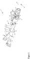
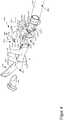
1 eine Explosionsansicht einer ersten Ausführungsform der vorliegenden Erfindung;2a eine Seitenansicht der ersten Ausführungsform der vorliegenden Erfindung aus1 , wobei die Arretierungsbaugruppe sich in der Freigabestellung befindet und wobei Teile der Therapiegaszufuhrleitung weggelassen worden sind;2b eine Aufsicht der ersten Ausführungsform der vorliegenden Erfindung aus1 , wobei die Arretierungsbaugruppe sich in der in2a gezeigten Freigabestellung befindet und wobei Teile der Therapiegaszufuhrleitung weggelassen worden sind;2c den AA-Schnitt aus2b ;3a eine Seitenansicht der ersten Ausführungsform der vorliegenden Erfindung aus1 , wobei die Arretierungsbaugruppe sich in der Arretierungsstellung befindet und wobei Teile der Therapiegaszufuhrleitung weggelassen worden sind;3b eine Aufsicht der zweiten Ausführungsform der vorliegenden Erfindung aus1 , wobei die Arretierungsbaugruppe sich in der in der in3a gezeigten Arretierungsstellung befindet und wobei Teile der Therapiegaszufuhrleitung weggelassen worden sind;3c den AA-Schnitt aus3b ;4 eine Explosionsansicht einer zweiten Ausführungsform der vorliegenden Erfindung;5a eine Seitenansicht der zweiten Ausführungsform der vorliegenden Erfindung aus4 , wobei die Arretierungsbaugruppe sich in der Freigabestellung befindet und wobei Teile der Therapiegaszufuhrleitung weggelassen worden sind;5b eine Aufsicht der zweiten Ausführungsform der vorliegenden Erfindung aus4 , wobei die Arretierungsbaugruppe sich in der Freigabestellung befindet und wobei Teile der Therapiegaszufuhrleitung weggelassen worden sind;5c den AA-Schnitt aus5b ;6a eine Seitenansicht der ersten Ausführungsform der vorliegenden Erfindung aus4 , wobei die Arretierungsbaugruppe sich in der Arretierungsstellung befindet und wobei Teile der Therapiegaszufuhrleitung weggelassen worden sind;6b eine Aufsicht der zweiten Ausführungsform der vorliegenden Erfindung aus4 , wobei die Arretierungsbaugruppe sich in der Arretierungsstellung befindet und wobei Teile der Therapiegaszufuhrleitung weggelassen worden sind; und6c den AA-Schnitt aus6b .
1 an exploded view of a first embodiment of the present invention;2a Figure 3 is a side view of the first embodiment of the present invention1 wherein the locking assembly is in the release position and parts of the therapeutic gas supply line have been omitted;2 B Figure 3 is a plan view of the first embodiment of the present invention1 , with the locking assembly in the in2a is shown release position and wherein parts of the therapy gas supply line have been omitted;2c the AA cut2 B ;3a Figure 3 is a side view of the first embodiment of the present invention1 wherein the locking assembly is in the locking position and with portions of the therapeutic gas supply line omitted;3b a plan view of the second embodiment of the present invention1 , with the locking assembly in the in3a shown locking position and wherein parts of the therapy gas supply line have been omitted;3c the AA cut3b ;4th an exploded view of a second embodiment of the present invention;5a Figure 3 is a side view of the second embodiment of the present invention4th wherein the locking assembly is in the release position and parts of the therapeutic gas supply line have been omitted;5b a plan view of the second embodiment of the present invention4th wherein the locking assembly is in the release position and parts of the therapeutic gas supply line have been omitted;5c the AA cut5b ;6a Figure 3 is a side view of the first embodiment of the present invention4th wherein the locking assembly is in the locking position and with portions of the therapeutic gas supply line omitted;6b a plan view of the second embodiment of the present invention4th wherein the locking assembly is in the locking position and with portions of the therapeutic gas supply line omitted; and6c the AA cut6b .
Über einen später im Detail beschriebenen Leitungsanschluss
Die Therapiegaszufuhrleitung
Der Leitungsanschluss
An dem ersten Brillenanschluss
Die Nasenbrille
Bei geeigneter Wahl der Flächen
Bei ausgebildeter Therapiegas-führenden Verbindung
Ist die Therapiegas-führende Verbindung
Es wird besonders bevorzugt, dass in der Arretierungsstellung der Arretierungsbaugruppe
Die Arretierungsbaugruppe
Befindet sich die Arretierungsbaugruppe
Befindet sich die Arretierungsbaugruppe
Ferner kann Material des Brillenanschlusses
Befindet sich die Arretierungsbaugruppe
Um zu verhindern, dass die Arretierungsbaugruppe
Die Zunge
Die Stellungssicherungsvorrichtung
Befindet sich der Vorsprung
Die Arretierungsbaugruppe
Anhand der
Teile, Abschnitte, Bereiche, Richtungen usw., welche in der zweiten Ausführungsform denen der ersten Ausführungsform entsprechen, werden mit einem um 1000 erhöhten Bezugszeichen versehen und es wird explizit auf die zugehörige Beschreibung der ersten Ausführungsform verwiesen, welche auch zur Beschreibung der zweiten Ausführungsform in Bezug auf die entsprechenden Teile, Abschnitte, Bereiche, Richtungen usw. zu verwenden ist. Die Bezugszeichen SP,
Die Hauptunterschiede der zweiten Ausführungsform zur ersten Ausführungsform sind das vorsehen eines Schwenkhebels
Der Leitungsanschluss
Der Schwenkhebel
Für die folgenden Winkelangaben kann eine parallel zur Unterseite
Jeder der Winkelbereiche a1 und a2 weist vorzugsweise eine Winkelbreite von 15° oder weniger auf.Each of the angular ranges a1 and a2 preferably has an angular width of 15 ° or less.
Die Stellungssicherungsvorrichtung
Wird der Schwenkhebel
Über die Verrastung des Raststegs
ZITATE ENTHALTEN IN DER BESCHREIBUNGQUOTES INCLUDED IN THE DESCRIPTION
Diese Liste der vom Anmelder aufgeführten Dokumente wurde automatisiert erzeugt und ist ausschließlich zur besseren Information des Lesers aufgenommen. Die Liste ist nicht Bestandteil der deutschen Patent- bzw. Gebrauchsmusteranmeldung. Das DPMA übernimmt keinerlei Haftung für etwaige Fehler oder Auslassungen.This list of the documents listed by the applicant was generated automatically and is included solely for the better information of the reader. The list is not part of the German patent or utility model application. The DPMA assumes no liability for any errors or omissions.
Zitierte PatentliteraturPatent literature cited
- WO 2014/142681 [0005]WO 2014/142681 [0005]
- DE 102018122516 [0046]DE 102018122516 [0046]
Claims (16)
Translated fromGermanPriority Applications (6)
| Application Number | Priority Date | Filing Date | Title |
|---|---|---|---|
| DE102019115639.4ADE102019115639A1 (en) | 2019-06-07 | 2019-06-07 | Nasal cannula with improved secured connection to a supply line |
| EP20731824.7AEP3980104A1 (en) | 2019-06-07 | 2020-06-04 | Nasal cannula with a better-secured connection to a supply line |
| CN202080042087.2ACN114096299A (en) | 2019-06-07 | 2020-06-04 | Nasal cannula for improved secure attachment to delivery lines |
| US17/615,708US20220233801A1 (en) | 2019-06-07 | 2020-06-04 | Nasal cannula with a better-secured connection to a supply line |
| JP2021572481AJP2022536307A (en) | 2019-06-07 | 2020-06-04 | Nasal cannula with improved secure connection to supply line |
| PCT/EP2020/065563WO2020245323A1 (en) | 2019-06-07 | 2020-06-04 | Nasal cannula with a better-secured connection to a supply line |
Applications Claiming Priority (1)
| Application Number | Priority Date | Filing Date | Title |
|---|---|---|---|
| DE102019115639.4ADE102019115639A1 (en) | 2019-06-07 | 2019-06-07 | Nasal cannula with improved secured connection to a supply line |
Publications (1)
| Publication Number | Publication Date |
|---|---|
| DE102019115639A1true DE102019115639A1 (en) | 2020-12-10 |
Family
ID=71078503
Family Applications (1)
| Application Number | Title | Priority Date | Filing Date |
|---|---|---|---|
| DE102019115639.4AWithdrawnDE102019115639A1 (en) | 2019-06-07 | 2019-06-07 | Nasal cannula with improved secured connection to a supply line |
Country Status (6)
| Country | Link |
|---|---|
| US (1) | US20220233801A1 (en) |
| EP (1) | EP3980104A1 (en) |
| JP (1) | JP2022536307A (en) |
| CN (1) | CN114096299A (en) |
| DE (1) | DE102019115639A1 (en) |
| WO (1) | WO2020245323A1 (en) |
Families Citing this family (1)
| Publication number | Priority date | Publication date | Assignee | Title |
|---|---|---|---|---|
| USD825053S1 (en)* | 2016-03-23 | 2018-08-07 | Fisher & Paykel Healthcare Limited | Nasal cannula |
Citations (3)
| Publication number | Priority date | Publication date | Assignee | Title |
|---|---|---|---|---|
| US20050077726A1 (en)* | 2003-10-03 | 2005-04-14 | White Craig Karl | Connector |
| DE112012003304T5 (en)* | 2011-08-10 | 2014-05-08 | Fisher & Paykel Healthcare Ltd. | Conduit connector for a device for ventilating patients |
| US20190022344A1 (en)* | 2015-09-04 | 2019-01-24 | Fisher & Paykel Healthcare Limited | Connectors for conduits |
Family Cites Families (8)
| Publication number | Priority date | Publication date | Assignee | Title |
|---|---|---|---|---|
| US7318437B2 (en)* | 2003-02-21 | 2008-01-15 | Resmed Limited | Nasal assembly |
| DE202004021758U1 (en)* | 2003-02-21 | 2010-09-30 | ResMed Ltd., Bella Vista | Nasal arrangement |
| NZ605600A (en)* | 2008-03-04 | 2014-11-28 | Resmed Ltd | Unobtrusive interface systems |
| US20150190600A1 (en)* | 2012-07-11 | 2015-07-09 | Koninklijkie Philips N.V. | Patient interface |
| WO2014110622A1 (en)* | 2013-01-18 | 2014-07-24 | Resmed Limited | Patient interface and method for making same |
| CN116899065A (en) | 2013-03-15 | 2023-10-20 | 费雪派克医疗保健有限公司 | Nasal cannula assemblies and related components |
| US10792449B2 (en)* | 2017-10-03 | 2020-10-06 | Breathe Technologies, Inc. | Patient interface with integrated jet pump |
| DE102018122516A1 (en) | 2018-09-14 | 2020-03-19 | Hamilton Medical Ag | Nasal cannula with improved, also asymmetrical flow guidance |
- 2019
- 2019-06-07DEDE102019115639.4Apatent/DE102019115639A1/ennot_activeWithdrawn
- 2020
- 2020-06-04USUS17/615,708patent/US20220233801A1/ennot_activeAbandoned
- 2020-06-04JPJP2021572481Apatent/JP2022536307A/enactivePending
- 2020-06-04WOPCT/EP2020/065563patent/WO2020245323A1/ennot_activeCeased
- 2020-06-04CNCN202080042087.2Apatent/CN114096299A/enactivePending
- 2020-06-04EPEP20731824.7Apatent/EP3980104A1/ennot_activeWithdrawn
Patent Citations (3)
| Publication number | Priority date | Publication date | Assignee | Title |
|---|---|---|---|---|
| US20050077726A1 (en)* | 2003-10-03 | 2005-04-14 | White Craig Karl | Connector |
| DE112012003304T5 (en)* | 2011-08-10 | 2014-05-08 | Fisher & Paykel Healthcare Ltd. | Conduit connector for a device for ventilating patients |
| US20190022344A1 (en)* | 2015-09-04 | 2019-01-24 | Fisher & Paykel Healthcare Limited | Connectors for conduits |
Also Published As
| Publication number | Publication date |
|---|---|
| WO2020245323A1 (en) | 2020-12-10 |
| US20220233801A1 (en) | 2022-07-28 |
| EP3980104A1 (en) | 2022-04-13 |
| JP2022536307A (en) | 2022-08-15 |
| CN114096299A (en) | 2022-02-25 |
Similar Documents
| Publication | Publication Date | Title |
|---|---|---|
| EP2220991B1 (en) | Instrument with self-releasing adjustment wheel | |
| DE202005015966U1 (en) | Connectors for media cables | |
| DE202015103406U1 (en) | connection system | |
| DE102017005718A1 (en) | Medical push button valve | |
| DE102019217984A1 (en) | Coupling element for a closed fluid transfer system, mating coupling element for such a coupling element and coupling system | |
| DE102020203153A1 (en) | Coupling element for a closed fluid transfer system, attachment for such a coupling element, coupling system and coupling kit | |
| DE2817922A1 (en) | SEALING DEVICE | |
| DE10203597A1 (en) | injection device | |
| WO2021175884A1 (en) | Coupling element for a closed fluid transfer system, counter coupling element for a coupling element of this type, and coupling system | |
| DE202012007845U1 (en) | catheter coupling | |
| EP3776750A1 (en) | Electrical plug-in connector part and electrical plug-in connection system with locking | |
| DE102014208473A1 (en) | Knife with automatic blade reset | |
| DE102015110343A1 (en) | Multi-part safety device for a syringe | |
| EP3310426B1 (en) | Male and female luer connector and luer connection system | |
| DE102017010477A1 (en) | Medical instrument with plastic handles with torsion protection | |
| DE102019115639A1 (en) | Nasal cannula with improved secured connection to a supply line | |
| EP3116563B1 (en) | Fluid cassette having a tilt-tolerant centering locking, and blood treatment device | |
| DE102020120641A1 (en) | Device for connecting a valve drive to a valve membrane | |
| DE102010026100A1 (en) | Quick coupling for fluid lines | |
| WO2021175881A1 (en) | Coupling element and coupling system for a closed fluid transfer system | |
| DE202016002850U1 (en) | Surgical hand instrument | |
| EP4021543B1 (en) | Connection component for a tracheal cannula, in particular for protecting against an unintentional closure of same | |
| EP2981241B1 (en) | Fluid valve and fluid connection system | |
| WO2018095677A1 (en) | Removal tool for a filter insert of a liquid filter | |
| EP2392847A2 (en) | Quick coupling for fluid conduits |
Legal Events
| Date | Code | Title | Description |
|---|---|---|---|
| R163 | Identified publications notified | ||
| R119 | Application deemed withdrawn, or ip right lapsed, due to non-payment of renewal fee |