DE102019109787A1 - Hygienic pipe adapter - Google Patents
Hygienic pipe adapterDownload PDFInfo
- Publication number
- DE102019109787A1 DE102019109787A1DE102019109787.8ADE102019109787ADE102019109787A1DE 102019109787 A1DE102019109787 A1DE 102019109787A1DE 102019109787 ADE102019109787 ADE 102019109787ADE 102019109787 A1DE102019109787 A1DE 102019109787A1
- Authority
- DE
- Germany
- Prior art keywords
- channel
- pipe adapter
- wall
- formation
- adapter
- Prior art date
- Legal status (The legal status is an assumption and is not a legal conclusion. Google has not performed a legal analysis and makes no representation as to the accuracy of the status listed.)
- Withdrawn
Links
- 230000007704transitionEffects0.000claimsabstractdescription29
- 238000004519manufacturing processMethods0.000claimsabstractdescription22
- 230000015572biosynthetic processEffects0.000claimsdescription61
- 238000005755formation reactionMethods0.000claimsdescription61
- 238000000034methodMethods0.000claimsdescription26
- 238000003801millingMethods0.000claimsdescription14
- 230000008569processEffects0.000claimsdescription14
- 238000012544monitoring processMethods0.000claimsdescription7
- 238000010327methods by industryMethods0.000description6
- 238000013461designMethods0.000description4
- 238000005520cutting processMethods0.000description3
- 230000000694effectsEffects0.000description3
- 238000007789sealingMethods0.000description3
- 239000000654additiveSubstances0.000description2
- 230000000996additive effectEffects0.000description2
- 238000004140cleaningMethods0.000description2
- 239000012530fluidSubstances0.000description2
- BUHVIAUBTBOHAG-FOYDDCNASA-N(2r,3r,4s,5r)-2-[6-[[2-(3,5-dimethoxyphenyl)-2-(2-methylphenyl)ethyl]amino]purin-9-yl]-5-(hydroxymethyl)oxolane-3,4-diolChemical compoundCOC1=CC(OC)=CC(C(CNC=2C=3N=CN(C=3N=CN=2)[C@H]2[C@@H]([C@H](O)[C@@H](CO)O2)O)C=2C(=CC=CC=2)C)=C1BUHVIAUBTBOHAG-FOYDDCNASA-N0.000description1
- 2380000101463D printingMethods0.000description1
- 241000307523Xenostegia mediaSpecies0.000description1
- 238000010521absorption reactionMethods0.000description1
- 230000006978adaptationEffects0.000description1
- 230000000712assemblyEffects0.000description1
- 238000000429assemblyMethods0.000description1
- 244000052616bacterial pathogenSpecies0.000description1
- 238000010364biochemical engineeringMethods0.000description1
- 238000011109contaminationMethods0.000description1
- 238000011161developmentMethods0.000description1
- 230000003670easy-to-cleanEffects0.000description1
- 238000005516engineering processMethods0.000description1
- 238000010348incorporationMethods0.000description1
- 238000003754machiningMethods0.000description1
- 238000000691measurement methodMethods0.000description1
- 230000007246mechanismEffects0.000description1
- 238000012986modificationMethods0.000description1
- 230000004048modificationEffects0.000description1
- 238000000465mouldingMethods0.000description1
- 230000003287optical effectEffects0.000description1
- 238000007514turningMethods0.000description1
Images


Classifications
- F—MECHANICAL ENGINEERING; LIGHTING; HEATING; WEAPONS; BLASTING
- F16—ENGINEERING ELEMENTS AND UNITS; GENERAL MEASURES FOR PRODUCING AND MAINTAINING EFFECTIVE FUNCTIONING OF MACHINES OR INSTALLATIONS; THERMAL INSULATION IN GENERAL
- F16L—PIPES; JOINTS OR FITTINGS FOR PIPES; SUPPORTS FOR PIPES, CABLES OR PROTECTIVE TUBING; MEANS FOR THERMAL INSULATION IN GENERAL
- F16L41/00—Branching pipes; Joining pipes to walls
- F16L41/08—Joining pipes to walls or pipes, the joined pipe axis being perpendicular to the plane of a wall or to the axis of another pipe
- F16L41/10—Joining pipes to walls or pipes, the joined pipe axis being perpendicular to the plane of a wall or to the axis of another pipe the extremity of the pipe being screwed into the wall
- G—PHYSICS
- G01—MEASURING; TESTING
- G01D—MEASURING NOT SPECIALLY ADAPTED FOR A SPECIFIC VARIABLE; ARRANGEMENTS FOR MEASURING TWO OR MORE VARIABLES NOT COVERED IN A SINGLE OTHER SUBCLASS; TARIFF METERING APPARATUS; MEASURING OR TESTING NOT OTHERWISE PROVIDED FOR
- G01D11/00—Component parts of measuring arrangements not specially adapted for a specific variable
- G01D11/30—Supports specially adapted for an instrument; Supports specially adapted for a set of instruments
- G—PHYSICS
- G01—MEASURING; TESTING
- G01F—MEASURING VOLUME, VOLUME FLOW, MASS FLOW OR LIQUID LEVEL; METERING BY VOLUME
- G01F23/00—Indicating or measuring liquid level or level of fluent solid material, e.g. indicating in terms of volume or indicating by means of an alarm
- G01F23/22—Indicating or measuring liquid level or level of fluent solid material, e.g. indicating in terms of volume or indicating by means of an alarm by measuring physical variables, other than linear dimensions, pressure or weight, dependent on the level to be measured, e.g. by difference of heat transfer of steam or water
- G01F23/24—Indicating or measuring liquid level or level of fluent solid material, e.g. indicating in terms of volume or indicating by means of an alarm by measuring physical variables, other than linear dimensions, pressure or weight, dependent on the level to be measured, e.g. by difference of heat transfer of steam or water by measuring variations of resistance of resistors due to contact with conductor fluid
- G01F23/241—Indicating or measuring liquid level or level of fluent solid material, e.g. indicating in terms of volume or indicating by means of an alarm by measuring physical variables, other than linear dimensions, pressure or weight, dependent on the level to be measured, e.g. by difference of heat transfer of steam or water by measuring variations of resistance of resistors due to contact with conductor fluid for discrete levels
- G—PHYSICS
- G01—MEASURING; TESTING
- G01F—MEASURING VOLUME, VOLUME FLOW, MASS FLOW OR LIQUID LEVEL; METERING BY VOLUME
- G01F23/00—Indicating or measuring liquid level or level of fluent solid material, e.g. indicating in terms of volume or indicating by means of an alarm
- G01F23/22—Indicating or measuring liquid level or level of fluent solid material, e.g. indicating in terms of volume or indicating by means of an alarm by measuring physical variables, other than linear dimensions, pressure or weight, dependent on the level to be measured, e.g. by difference of heat transfer of steam or water
- G01F23/26—Indicating or measuring liquid level or level of fluent solid material, e.g. indicating in terms of volume or indicating by means of an alarm by measuring physical variables, other than linear dimensions, pressure or weight, dependent on the level to be measured, e.g. by difference of heat transfer of steam or water by measuring variations of capacity or inductance of capacitors or inductors arising from the presence of liquid or fluent solid material in the electric or electromagnetic fields
- G01F23/263—Indicating or measuring liquid level or level of fluent solid material, e.g. indicating in terms of volume or indicating by means of an alarm by measuring physical variables, other than linear dimensions, pressure or weight, dependent on the level to be measured, e.g. by difference of heat transfer of steam or water by measuring variations of capacity or inductance of capacitors or inductors arising from the presence of liquid or fluent solid material in the electric or electromagnetic fields by measuring variations in capacitance of capacitors
- G01F23/268—Indicating or measuring liquid level or level of fluent solid material, e.g. indicating in terms of volume or indicating by means of an alarm by measuring physical variables, other than linear dimensions, pressure or weight, dependent on the level to be measured, e.g. by difference of heat transfer of steam or water by measuring variations of capacity or inductance of capacitors or inductors arising from the presence of liquid or fluent solid material in the electric or electromagnetic fields by measuring variations in capacitance of capacitors mounting arrangements of probes
- G—PHYSICS
- G01—MEASURING; TESTING
- G01K—MEASURING TEMPERATURE; MEASURING QUANTITY OF HEAT; THERMALLY-SENSITIVE ELEMENTS NOT OTHERWISE PROVIDED FOR
- G01K13/00—Thermometers specially adapted for specific purposes
- G01K13/02—Thermometers specially adapted for specific purposes for measuring temperature of moving fluids or granular materials capable of flow
- G—PHYSICS
- G01—MEASURING; TESTING
- G01L—MEASURING FORCE, STRESS, TORQUE, WORK, MECHANICAL POWER, MECHANICAL EFFICIENCY, OR FLUID PRESSURE
- G01L19/00—Details of, or accessories for, apparatus for measuring steady or quasi-steady pressure of a fluent medium insofar as such details or accessories are not special to particular types of pressure gauges
- G01L19/0007—Fluidic connecting means
- G01L19/003—Fluidic connecting means using a detachable interface or adapter between the process medium and the pressure gauge
Landscapes
- Physics & Mathematics (AREA)
- General Physics & Mathematics (AREA)
- Engineering & Computer Science (AREA)
- General Engineering & Computer Science (AREA)
- Thermal Sciences (AREA)
- Fluid Mechanics (AREA)
- Power Engineering (AREA)
- Mechanical Engineering (AREA)
- Electromagnetism (AREA)
- Rigid Pipes And Flexible Pipes (AREA)
- Investigating Or Analyzing Materials By The Use Of Electric Means (AREA)
Abstract
Translated fromGerman
Description
Translated fromGermanDie Erfindung betrifft einen Rohradapter zum Führen eines Mediums, eine Anordnung zur Bestimmung und/oder Überwachung zumindest einer Prozessgröße mit einem Sensor und einem erfindungsgemäßen Rohradapter, sowie ein Verfahren zur Herstellung eines erfindungsgemäßen Rohradapters. Der Sensor ist dabei insbesondere in den Rohradapter einbringbar, welcher wiederum beispielsweise in ein bestehendes Rohrleitungssystem integriert werden kann.The invention relates to a pipe adapter for guiding a medium, an arrangement for determining and / or monitoring at least one process variable with a sensor and a pipe adapter according to the invention, and a method for producing a pipe adapter according to the invention. The sensor can in particular be introduced into the pipe adapter, which in turn can be integrated, for example, into an existing pipe system.
Messanordnungen mit einem Sensor und einem Rohradapter werden in der Automatisierungstechnik im Zusammenhang mit einer Vielzahl von Messgeräten und/oder Feldgeräten zur Bestimmung unterschiedlicher Prozessgrößen eingesetzt, welche in großer Vielfalt von der Anmelderin hergestellt und vertrieben werden. Die Prozessgröße ist beispielsweise der Durchfluss oder der Füllstand eines strömenden Fluides, oder auch der Druck, die Dichte, die Viskosität, die Leitfähigkeit, die Temperatur oder der ph-Wert eines Fluides. Aber auch optische Sensoren, wie Trübungs- oder Absorptionssensoren sind bekannt und fallen unter die vorliegende Erfindung.Measuring arrangements with a sensor and a pipe adapter are used in automation technology in connection with a large number of measuring devices and / or field devices for determining different process variables, which are manufactured and sold in great variety by the applicant. The process variable is, for example, the flow rate or the fill level of a flowing fluid, or also the pressure, density, viscosity, conductivity, temperature or pH value of a fluid. Optical sensors, such as turbidity or absorption sensors, are also known and fall under the present invention.
Die Sensoren werden in vielen Fällen mittels geeigneter Dichtungsmechanismen form- und/oder kraftschlüssig in die Rohradapter integriert oder auch direkt damit verschweißt und/oder verklebt. Fern sind dem Fachmann zahlreiche Mittel bekannt, mittels denen ein Rohradapter in ein bestehendes Rohrleitungssystem integriert werden kann.In many cases, the sensors are integrated into the pipe adapter in a form-fitting and / or force-fitting manner by means of suitable sealing mechanisms, or they are also welded and / or glued directly to them. Furthermore, numerous means are known to the person skilled in the art by means of which a pipe adapter can be integrated into an existing pipe system.
Beim Einbringen des jeweiligen Sensors in einen Rohradapter können nachteilige Spalte, Fugen und/oder Toträume entstehen. Für eine Reihe von Anwendungen, wie in der sterilen Verfahrenstechnik, beispielsweise im Bereich der Pharmazie, Nahrungs- und/oder Lebensmittelindustrie, sind solche Spalte, Fugen und/oder Toträume zwischen den einzelnen Komponenten nicht oder nur in sehr begrenztem Maße akzeptabel. In solchen Verbindungsbereichen finden sich nämlich potentielle Sammelbecken für gesundheitsgefährdende Keime. Um beispielsweise Ablagerungen bzw. die Bildung eines Biofilms innerhalb einer Rohrleitung zu verhindern, sollte eine möglichst rückstandsfreie Reinigung gewährleistet werden.When inserting the respective sensor into a pipe adapter, disadvantageous gaps, joints and / or dead spaces can arise. For a number of applications, such as in sterile process engineering, for example in the pharmaceutical, food and / or food industry, such gaps, joints and / or dead spaces between the individual components are not or only to a very limited extent acceptable. In such connection areas there are potential reservoirs for harmful germs. In order, for example, to prevent deposits or the formation of a biofilm within a pipeline, cleaning should be guaranteed as residue-free as possible.
In diesem Zusammenhang haben verschiedene internationale oder nationale Kontrollbehörden Standards, u. a. für die Herstellung, und Ausgestaltung von für die sterile Verfahrenstechnik zugelassenem Equipment erarbeitet. Beispielhaft sei hier auf die jeweiligen Standards der „American Society of Mechanical Engineers“ (ASME), insbesondere auf den sog. „ASME Bioprocessing Equipment - Standard“ (BPE), der „3-A Sanitary Standards Incorporation“ (3-A), oder auch der „European Hygienic Design Group“ (EHEDG) verwiesen. Die Standards gemäß ASME, BPE und 3A sind dabei insbesondere für den amerikanischen Raum relevant, während der Standard gemäß EHEDG mehrheitlich in Europa zum Tragen kommt. Typische in diesen Standards formulierte Anforderungen an ein Bauteil betreffen insbesondere die Geometrie und/oder Oberfläche des jeweiligen Bauteils, welches derart beschaffen sein sollte, dass sich keine Ablagerungen bilden können und das jeweilige Bauteil einfach zu reinigen und/oder sterilisieren ist. Beispielsweise sollten keine schmalen Spalte auftreten.In this context, various international or national control authorities have standards, u. a. for the production and design of equipment approved for sterile process engineering. For example, the respective standards of the "American Society of Mechanical Engineers" (ASME), in particular the so-called "ASME Bioprocessing Equipment - Standard" (BPE), the "3-A Sanitary Standards Incorporation" (3-A), or the “European Hygienic Design Group” (EHEDG). The standards according to ASME, BPE and 3A are particularly relevant for the American area, while the standard according to EHEDG is mostly used in Europe. Typical requirements for a component formulated in these standards relate in particular to the geometry and / or surface of the respective component, which should be designed in such a way that no deposits can form and the respective component is easy to clean and / or sterilize. For example, there should be no narrow gaps.
In Bezug auf mit diesen Standards konforme Messgeräte sei beispielsweise auf der
Aus der
Die
Ausgehend vom genannten Stand der Technik liegt der vorliegenden Erfindung die Aufgabe zugrunde, eine Messstelle bereitzustellen, welche auf besonders einfache Weise den üblichen Hygiene-Anforderungen gerecht wird.Proceeding from the prior art mentioned, the present invention is based on the object of providing a measuring point which meets the usual hygiene requirements in a particularly simple manner.
Diese Aufgabe wird gelöst durch den Rohradapter gemäß Anspruch 1, durch die Anordnung nach Anspruch 9 und durch das Verfahren nach Anspruch 10.This object is achieved by the pipe adapter according to
Hinsichtlich des Rohradapters wird die Aufgabe gelöst durch einen Rohradapter für eine Rohrleitung zum Führen eines Mediums umfassend einen Rohrleitungsabschnitt mit einem rohrförmigen, ersten Kanal zum Einbringen des Rohrleitungsabschnitts in die Rohrleitung, und einem rohrförmigen zweiten Kanal, welcher in einem ersten vorgebbaren Winkel, insbesondere senkrecht, zum ersten Kanal angeordnet und mit dem ersten Kanal verbunden ist. Erfindungsgemäß ist in einem Übergangsbereich zwischen einer Wandung des ersten und einer Wandung des zweiten Kanals zumindest eine Ausformung in eine Wandung des ersten und/oder zweiten Kanals eingebracht. Im Falle, dass der zweite Kanal bezüglich seiner Längsachse senkrecht zur Längsachse des ersten Kanals angeordnet ist, handelt es sich bei dem Rohradapter um ein T-Stück.With regard to the pipe adapter, the object is achieved by a pipe adapter for a pipeline for guiding a medium comprising a pipeline section with a tubular, first channel for introducing the pipeline section into the pipeline, and a tubular second channel which, at a first predeterminable angle, in particular perpendicular, is arranged to the first channel and connected to the first channel. According to the invention, in a transition area between a wall of the first and a wall of the second channel, at least one formation is made in a wall of the first and / or second channel. In the event that the second channel is arranged perpendicular to the longitudinal axis of the first channel with respect to its longitudinal axis, the pipe adapter is a T-piece.
Die Ausformung dient dazu, Toträume und/oder Spalte im Übergangsbereich, insbesondere im Falle, dass eine Vorrichtung zur Bestimmung und/oder Überwachung einer Prozessgröße in den Rohradapter eingebracht ist, zu verhindern. Eine Ausformung im Sinne der vorliegenden Erfindung ist ein vorgebbares Volumen des Rohrleitungsabschnitts im Übergangsbereich, welches aus den Wandungen des ersten und/oder zweiten Kanals entfernt wird. Die genaue Geometrie der Ausformung ist unter anderem abhängig von der Geometrie des Rohrleitungsabschnitts sowie vom jeweils angewendeten Herstellungsverfahren.The formation serves to prevent dead spaces and / or gaps in the transition area, in particular in the event that a device for determining and / or monitoring a process variable is introduced into the pipe adapter. A formation within the meaning of the present invention is a predeterminable volume of the pipeline section in the transition region, which is removed from the walls of the first and / or second channel. The exact geometry of the formation depends, among other things, on the geometry of the pipe section and on the manufacturing process used.
Die Wandungen der beiden rohrförmigen Kanäle sind üblicherweise gewölbt ausgebildet, insbesondere weisen sie kreisrunde Querschnittsflächen auf. Entsprechend ist die Öffnung, durchwelche die beiden Kanäle miteinander verbunden sind, ebenfalls gewölbt ausgebildet. Dies kann nachteilig zur Bildung von Ablagerungen im Übergangsbereich zwischen dem Rohradapter und einer in den Rohradapter eingebrachten Vorrichtung führen. Durch die zumindest eine Ausformung im Übergangsbereich zwischen den beiden Kanälen können solche nachteiligen Effekte jedoch deutlich reduziert werden. So gewährleistet die erfindungsgemäße Ausgestaltung des Rohradapters einen spalt- und/oder totraumfreien Übergang zwischen der Wandung, insbesondere Innenwandung des ersten Kanals und einer in den zweiten Kanal einbringbaren Komponente eines Messgeräts.The walls of the two tubular channels are usually arched, in particular they have circular cross-sectional areas. Correspondingly, the opening through which the two channels are connected to one another is also arched. This can disadvantageously lead to the formation of deposits in the transition area between the pipe adapter and a device introduced into the pipe adapter. Such disadvantageous effects can, however, be significantly reduced by the at least one formation in the transition region between the two channels. The design of the pipe adapter according to the invention thus ensures a gap-free and / or dead space-free transition between the wall, in particular the inner wall of the first channel and a component of a measuring device that can be introduced into the second channel.
Vorteilhaft bedarf es zur Einhaltung der gängigen Hygieneanforderungen keiner weiteren Modifikation des jeweiligen Sensors. Die Komponente, bzw. eine Stirnfläche der Komponente des Sensors, kann so angeordnet werden, dass diese im Wesentlichen frontbündig mit der Wandung des ersten Kanals im Bereich der Öffnung, an oder in welche der zweite Kanal mündet, abschließt. Es können also ohne spezielle Anforderungen an den Sensor die gängigen Hygienebestimmungen eingehalten werden, beispielsweise kann ein spaltfreier Übergang zwischen der Komponente und der Wandung des ersten Kanals gewährleistet werden.Advantageously, no further modification of the respective sensor is required in order to comply with the common hygiene requirements. The component, or an end face of the component of the sensor, can be arranged in such a way that it ends essentially flush with the wall of the first channel in the area of the opening at or into which the second channel opens. The current hygiene regulations can therefore be complied with without special requirements for the sensor, for example a gap-free transition between the component and the wall of the first channel can be guaranteed.
Der Rohradapter umfasst im Bereich des ersten Kanals zwei weitere Öffnungen, beispielsweise zum Einbringen des Rohradapters in ein bestehendes Rohrleitungssystem. Diese beiden Öffnungen sind im Falle eines geraden Rohrleitungsabschnitts üblicherweise entlang einer gemeinsamen Längsachse des Rohrleitungsabschnitts angeordnet. Die vorliegende Erfindung ist jedoch keinesfalls auf derartige Rohrleitungsabschnitte begrenzt. Vielmehr kann der Rohrleitungsabschnitt auch zumindest ein gebogenes Segment aufweisen.The pipe adapter includes two further openings in the area of the first channel, for example for introducing the pipe adapter into an existing pipe system. In the case of a straight pipe section, these two openings are usually arranged along a common longitudinal axis of the pipe section. However, the present invention is in no way limited to such pipeline sections. Rather, the pipeline section can also have at least one curved segment.
Zur Befestigung des Rohrleitungsabschnittes in einem bestehenden Rohrleitungssystem sind alle dem Fachmann allgemein bekannten Befestigungsweisen denkbar, wie beispielsweise Flansch-, Schweiß- oder Klemmverbindungen. Die Länge der Kanäle bzw. die Dimensionierung des Rohrleitungsabschnitts ist jeweils an eine gewünschte Anwendung anpassbar. So kann es für manche Anwendungen beispielsweise vorteilhaft, die Länge des ersten Kanals zu minimieren.To fasten the pipe section in an existing pipe system, all fastening methods generally known to the person skilled in the art are conceivable, such as flange, welded or clamped connections. The length of the channels or the dimensioning of the pipe section can be adapted to a desired application. For example, it can be advantageous for some applications to minimize the length of the first channel.
Es sei ferner darauf verwiesen, dass es sich bei dem erfindungsgemäßen Rohradapter sowohl um ein einstückig hergestelltes als auch um ein aus mehreren Komponenten zusammengefügtes Bauelement handeln kann. Dies kann je nach eingesetztem Herstellungsverfahren variieren. Beispielsweise kann es sich bei dem Rohradapter, oder zumindest einzelner Komponenten des Rohradapters um gedrehte und/oder gefräste Bauteile handeln. Einzelne Komponenten können beispielsweise auch miteinander verschweißt werden. Aber auch andere geeignete dem Fachmann hinlänglich bekannte Fertigungsverfahren, beispielsweise generative, oder auch additive, Fertigungsverfahren sind zur Herstellung eines erfindungsgemäßen Rohradapters möglich. Im Falle eines generativen, oder auch additiven Fertigungsverfahrens, wie beispielsweise einem 3D-Druck-Verfahren, werden die Bauteile in einem Urformprozess erzeugt. Solche generativen Fertigungsverfahren, welche im Prinzip eine industrialisierte und massentaugliche Weiterentwicklung des sogenannten Rapid Prototyping darstellen, halten seit einigen Jahren zunehmend Einzug in der industriellen Fertigung. Die gängigen, unterschiedlichen Herstellungsverfahren sind dem Fachmann bestens bekannt und werden deswegen an dieser Stelle nicht im Detail erläutert.It should also be pointed out that the pipe adapter according to the invention can be a component manufactured in one piece or a component assembled from several components. This can vary depending on the manufacturing process used. For example, the pipe adapter or at least individual components of the pipe adapter can be turned and / or milled components. Individual components can also be welded together, for example. However, other suitable manufacturing processes that are sufficiently well known to the person skilled in the art, for example generative or also additive manufacturing processes, are possible for manufacturing a pipe adapter according to the invention. In the case of a generative or additive manufacturing process, such as a 3D printing process, the components are produced in a primary forming process. Such generative manufacturing processes, which in principle represent an industrialized and mass-produced further development of so-called rapid prototyping, have been increasingly finding their way into industrial manufacturing for some years. The common, different manufacturing processes are very well known to the person skilled in the art and are therefore not explained in detail at this point.
In einer Ausgestaltung ist in einem Endbereich des zweiten Kanals, insbesondere im Bereich einer weiteren Öffnung des zweiten Kanals, ein Gewinde in eine Wandung des zweiten Kanals eingebracht. Mittels des Gewindes kann ein Messgerät oder eine Komponente eines Messgeräts in dem Rohradapter lösbar eingebracht werden.In one embodiment, a thread is made in a wall of the second channel in an end area of the second channel, in particular in the area of a further opening of the second channel. By means of the thread, a Measuring device or a component of a measuring device can be detachably introduced into the pipe adapter.
Eine bevorzugte Ausgestaltung beinhaltet, dass der Rohradapter einen dritten, rohrförmigen Kanal umfasst, welcher in einem zweiten vorgebbaren Winkel zum ersten Kanal angeordnet, und mit dem ersten Kanal verbunden ist. Bevorzugt verlaufen die Längsachsen des zweiten und dritten Kanals parallel zueinander, insbesondere fluchten sie miteinander, so dass sich der zweite und dritte Kanal relativ zum ersten Kanal gegenüberliegen. In diesem Falle können beispielsweise zwei Messgeräte oder zwei Komponenten von einem oder zwei Messgeräten in den Rohradapter eingebracht werden.A preferred embodiment includes that the pipe adapter comprises a third, tubular channel which is arranged at a second predeterminable angle to the first channel and is connected to the first channel. The longitudinal axes of the second and third channels preferably run parallel to one another, in particular they are aligned with one another, so that the second and third channels are opposite one another relative to the first channel. In this case, for example, two measuring devices or two components of one or two measuring devices can be introduced into the pipe adapter.
Noch eine bevorzugte Ausgestaltung des Rohradapters beinhaltet, dass in dem Übergangsbereich zwischen den Wandungen des ersten und zweiten Kanals zumindest zwei Ausformungen eingebracht sind. Die beiden Ausformungen sind insbesondere in Bezug auf ihre Geometrie gleich ausgestaltet und symmetrisch zueinander angeordnet.Another preferred embodiment of the pipe adapter includes that at least two formations are made in the transition region between the walls of the first and second channels. The two formations are configured identically, in particular with regard to their geometry, and are arranged symmetrically to one another.
Es ist von Vorteil, wenn die beiden Ausformungen bezogen auf eine Querschnittsfläche des zweiten Kanals einander gegenüber liegend angeordnet sind. Es ist ebenfalls von Vorteil, wenn die beiden Ausformungen bezogen auf eine Längsachse des ersten Kanals einander gegenüberliegend angeordnet sind. In diesen Bereichen ist das Bilden von Ablagerungen oder Entstehen von Toträumen besonders wahrscheinlich.It is advantageous if the two formations are arranged opposite one another in relation to a cross-sectional area of the second channel. It is also advantageous if the two formations are arranged opposite one another in relation to a longitudinal axis of the first channel. The formation of deposits or the creation of dead spaces is particularly likely in these areas.
In einer weiteren Ausgestaltung des Rohradapters weist die zumindest eine Ausformung eine sichelförmige Geometrie auf. Die Oberfläche der ersten und/oder zweiten Wandung des ersten und/oder zweiten Kanals im Bereich der Ausformung ist demnach zumindest teilweise zylinderförmig ausgestaltet. Die zumindest eine Ausformung kann aber auf unterschiedlichste Arten und Weisen ausgestaltet sein. Insbesondere kann sie auch eine rotationssymmetrische Geometrie aufweisen.In a further embodiment of the pipe adapter, the at least one formation has a sickle-shaped geometry. The surface of the first and / or second wall of the first and / or second channel in the area of the formation is accordingly at least partially cylindrical. The at least one formation can, however, be designed in the most varied of ways. In particular, it can also have a rotationally symmetrical geometry.
In noch einer Ausgestaltung des Rohradapters ist zumindest in einem Randbereich der zumindest einen Ausformung ein Verlängerungsbereich vorgesehen, welcher sich insbesondere tangential an die Ausformung anschließt. Im Falle, dass zumindest zwei Ausformungen in den Rohradapter eingebacht sind, kann der Verlängerungsbereich auch derart ausgestaltet sein, dass er die beiden Ausformungen miteinander verbindet.In yet another embodiment of the pipe adapter, an extension area is provided at least in an edge area of the at least one formation, which, in particular, adjoins the formation tangentially. In the event that at least two formations are incorporated into the pipe adapter, the extension area can also be designed such that it connects the two formations to one another.
Die der vorliegenden Erfindung zugrundeliegende Aufgabe wird ferner gelöst durch eine Anordnung zur Bestimmung und/oder Überwachung zumindest einer Prozessgröße eines Mediums in einer Rohrleitung, umfassend
- - eine Vorrichtung zur Bestimmung und/oder Überwachung der zumindest einen Prozessgröße, und
- - einen erfindungsgemäßen Rohradapter.
- a device for determining and / or monitoring the at least one process variable, and
- - A pipe adapter according to the invention.
Zumindest eine Komponente der Vorrichtung ist in den zweiten Kanal des Rohradapters einbringbar oder eingebracht. In einer Ausgestaltung handelt es sich bei der zumindest einen Komponente des Messgeräts um eine Komponente eines Sensorelements. Insbesondere handelt es sich bei der Komponente um eine Komponente, welche im fortlaufenden Betrieb des Messgeräts zumindest zeitweise und/oder teilweise, insbesondere im Bereich einer Stirnfläche, prozessberührend, also mediumsberührend, ist. In dieser Hinsicht ist es von Vorteil, wenn der Rohradapter eine Befestigungseinheit, insbesondere ein Gewinde, zur Befestigung der zumindest einen Komponente an oder in dem Rohradapter umfasst. Die Befestigungseinheit ist dabei bevorzugt im dem ersten Kanal abgewandten Endbereich des zweiten Kanals angeordnet sein.At least one component of the device can be introduced or introduced into the second channel of the pipe adapter. In one embodiment, the at least one component of the measuring device is a component of a sensor element. In particular, the component is a component which, during continuous operation of the measuring device, is at least temporarily and / or partially, in particular in the area of an end face, in contact with the process, that is, in contact with the medium. In this regard, it is advantageous if the pipe adapter comprises a fastening unit, in particular a thread, for fastening the at least one component on or in the pipe adapter. The fastening unit is preferably arranged in the end region of the second channel facing away from the first channel.
Da die Vorrichtung bzw. die Komponente der Vorrichtung durch das Einbringen der zumindest einen Ausformung in den Rohradapter im Wesentlichen frontbündig mit der Wandung des ersten Kanals abschließt, beschränkt sich der Kontaktbereich zwischen der Vorrichtung und dem Medium vorteilhaft auf diese Fläche. Die frontbündige Anordnung gewährleistet somit eine im Wesentlichen rückstandsfreie Reinigung der Anordnung, was insbesondere für Anwendungen in der sterilen Verfahrenstechnik relevant ist.Since the device or the component of the device is essentially flush with the wall of the first channel by introducing the at least one recess into the pipe adapter, the contact area between the device and the medium is advantageously limited to this area. The front-flush arrangement thus ensures that the arrangement is essentially residue-free cleaning, which is particularly relevant for applications in sterile process engineering.
Der zweite und ggf. der dritte Kanal ist/sind vorteilhaft derart dimensioniert, dass die Vorrichtung bzw. die Komponente der Vorrichtung, welche in den zweiten Kanal eingebracht wird, passgenau in diesen einbringbar ist. Im Falle einer zylindrischen Ausgestaltung der Vorrichtung bzw. der Komponente weist also auch der zweite Kanal eine zylinderförmige Geometrie auf, wobei die Querschnittsfläche an die Dimensionierung der Vorrichtung bzw. der Komponente der Vorrichtung angepasst ist. In einer Ausgestaltung kann es sich bei dem zweiten Kanal auch um zumindest einen Teil eines Gehäuses der Komponente handeln.The second and possibly the third channel is / are advantageously dimensioned in such a way that the device or the component of the device which is introduced into the second channel can be introduced into the second channel with an accurate fit. In the case of a cylindrical configuration of the device or the component, the second channel also has a cylindrical geometry, the cross-sectional area being adapted to the dimensions of the device or the component of the device. In one embodiment, the second channel can also be at least part of a housing of the component.
In einer Ausgestaltung der Anordnung ist ein Übergang zwischen dem Rohradapter und der Vorrichtung im Bereich des ersten Kanals im Wesentlichen spaltfrei und/oder totraumfrei. Die Vorrichtung oder die Komponente schließt also im in den zweiten Kanal eingebrachten Zustand im Wesentlichen frontbündig mit der Wandung des ersten Kanals ab. Zwischen der Vorrichtung bzw. Komponente und der Wandung des ersten Kanals können sich entsprechend vorteilhaft keine Ablagerungen oder Verschmutzungen anreichern.In one embodiment of the arrangement, a transition between the pipe adapter and the device in the region of the first channel is essentially free of gaps and / or dead space. The device or the component is thus essentially flush with the wall of the first channel when it is introduced into the second channel. Correspondingly, advantageously, no deposits or contamination can accumulate between the device or component and the wall of the first channel.
Die Vorrichtung oder Komponente kann beispielsweise mittels eines Dichtelements in den zweiten Kanal eingebracht sein. Hierbei ist es von Vorteil, wenn es sich bei dem Dichtelement um einen O-Ring handelt.The device or component can be introduced into the second channel, for example, by means of a sealing element. It is advantageous here if the sealing element is an O-ring.
Eine weitere Ausgestaltung sieht vor, dass es sich bei der Vorrichtung um ein kapazitives und/oder konduktives Messgerät handelt. Das Sensorelement der Vorrichtung umfasst dann zumindest eine erste Elektrode und zumindest eine elektrisch von der ersten Elektrode isolierte zweite Elektrode aus. Die zweite Elektrode wird allgemein hin auch als Guard-Elektrode bezeichnet. Es handelt sich in dieser Ausgestaltung also um einen frontbündigen, kapazitiven und/oder konduktiven Sensor, welcher bevorzugt zur Detektion eines vorgebbaren Füllstands, oder der Leitfähigkeit des Mediums eingesetzt wird. Derartige, auch als Multisensoren bezeichnete, Sensoren sind beispielsweise aus den Dokumenten
Bei der zumindest einen Komponente des Messgeräts handelt es sich dann bevorzugt um die Elektrodenbaugruppe mit einer, insbesondere kreisförmigen, Stirnfläche, wobei zumindest eine Elektrode der Elektrodenbaugruppe im Wesentlichen mit der Stirnfläche abschließt. Die Stirnfläche kann sowohl planar als auch zumindest teilweise gewölbt ausgestaltet sein. Im in den Rohradapter eingebrachten Zustand schließt die Elektrodenbaugruppe vorteilhaft im Wesentlichen frontbündig mit der Wandung des ersten Kanals ab.The at least one component of the measuring device is then preferably the electrode assembly with an, in particular circular, end face, at least one electrode of the electrode assembly essentially flush with the end face. The end face can be designed both planar and at least partially curved. In the state in which it has been introduced into the pipe adapter, the electrode assembly advantageously terminates essentially flush with the wall of the first channel.
Es kann sich aber ebenfalls um eine andere Gattung von Messgerät handeln. Ein weiteres Beispiel für ein Messgerät ist beispielsweise eine Vorrichtung zur Bestimmung und/oder Überwachung des Drucks eines Mediums.However, it can also be a different type of measuring device. Another example of a measuring device is, for example, a device for determining and / or monitoring the pressure of a medium.
Die der Erfindung zugrunde liegende Aufgabe wird ferner gelöst durch ein Verfahren zur Herstellung eines erfindungsgemäßen Rohradapters umfassend folgende Verfahrensschritte:
- - Bereitstellen eines Rohrleitungsabschnitts mit einem rohrförmigen, ersten Kanal und einem rohrförmigen zweiten Kanal, welcher in einem ersten vorgebbaren Winkel zum ersten Kanal angeordnet und mit dem ersten Kanal verbunden ist, und
- - Fräsen von zumindest einer Ausformung in eine Wandung des ersten und/oder zweiten Kanals in einem Übergangsbereich zwischen einer Wandung des ersten und einer Wandung des zweiten Kanals.
- - Providing a pipe section with a tubular, first channel and a tubular second channel, which is arranged at a first predeterminable angle to the first channel and is connected to the first channel, and
- Milling of at least one formation in a wall of the first and / or second channel in a transition area between a wall of the first and a wall of the second channel.
Vorteilhaft lässt sich die zumindest eine Ausformung nach Herstellung des Rohrleitungsabschnitts in den Übergangsbereich zwischen den beiden Kanälen einfräsen. So können einerseits bestehende Rohradapter mit zwei verbunden Kanälen nachträglich bearbeitet werden und somit für eine Verwendung in der sterilen Verfahrenstechnik ausgebildet werden. Aber auch bei der vollständigen erfindungsgemäßen Fertigung eines erfindungsgemäßen Rohradapters ergeben sich verschiedene Vorteile. In einem ersten Fertigungsschritt werden die beiden Kanäle in einen Rohrleitungsabschnitt eingebracht. Hierfür sind keine besonderen Maßnahmen erforderlich, so dass beispielsweise Drehverfahren zur Einbringung der Kanäle verwendet werden können. Eine derartige Fertigung ist schnell und einfach zu realisieren und bedarf nur einem geringen Aufwand. In einem zweiten Arbeitsschritt wird dann die zumindest eine Ausformung eingebracht. Hierzu kann ein Fräser vorteilhaft durch eine Öffnung des Rohradapters in denselben eingeführt werden, um die Ausformung zu fräsen. Somit kann auch die Anpassung der Geometrie im Innenvolumen des Rohradapters zur Gewährleistung einer Verwendung im Bereich der sterilen Verfahrenstechnik auf einfache Art und Weise realisiert werden. Es bedarf keiner kompexen und aufwendigen, vielstufigen Fertigungsabläufe.The at least one formation can advantageously be milled into the transition region between the two channels after the pipe section has been produced. On the one hand, existing pipe adapters with two connected channels can be subsequently processed and thus designed for use in sterile process engineering. However, various advantages also result from the complete production according to the invention of a pipe adapter according to the invention. In a first production step, the two channels are introduced into a pipe section. No special measures are required for this, so that, for example, turning methods can be used to introduce the channels. Such a production can be realized quickly and easily and requires only little effort. In a second work step, the at least one formation is then introduced. For this purpose, a milling cutter can advantageously be inserted into the pipe adapter through an opening in order to mill the formation. The adaptation of the geometry in the inner volume of the tube adapter to ensure use in the field of sterile process engineering can thus also be implemented in a simple manner. There is no need for complex and costly, multi-level production processes.
Es ist von Vorteil, wenn zum Fräsen ein Kugelfräser und/oder ein Kreissegmentfräser verwendet wird. Mit derartigen Fräsern lässt sich auf besonders einfache Weise eine Ausformung in den Übergangsbereich einbringen. Insbesondere kann eine sichelförmige Ausformung eingebracht werden.It is advantageous if a spherical cutter and / or a circular segment cutter is used for milling. With such milling cutters, a formation can be made in the transition area in a particularly simple manner. In particular, a sickle-shaped shape can be introduced.
Es ist ebenfalls von Vorteil, wenn ein Werkzeug, insbesondere ein Schnitt- oder Zerspanungswerzeug, zum Fräsen der zumindest einen Ausformung durch eine erste und/oder zweite Öffnung des ersten Kanals, welche zum Einbringen des Rohradapters in die Rohrleitung dient, oder durch eine Öffnung des zweiten Kanals, in ein Innenvolumen des Rohradapters eingebracht wird. Durch das Einbringen des Fräsers durch die Öffnung des zweiten Kanals kann beispielsweise eine zusammenhängende Rotationsfläche, und damit eine einzige rotationssymmetrische Ausformung, oder auch mehrere, insbesondere voneinander getrennte Ausformungen, hergestellt werden. Beim Einbringen des Fräsers durch zumindest eine Öffnung des ersten Kanals ist es wiederum beispielsweise einerseits möglich, dass während des gesamten Fräsvorgangs einer Ausformung der Fräser durch dieselbe Öffnung in den ersten Kanal eingebracht wird. Es ist aber ebenso denkbar, dass der Fräser zur Herstellung einer Ausformung zeitweise durch unterschiedliche Öffnungen, insbesondere des ersten Kanals, eingebracht wird.It is also advantageous if a tool, in particular a cutting or machining tool, for milling the at least one formation through a first and / or second opening of the first channel, which is used to introduce the pipe adapter into the pipeline, or through an opening of the second channel, is introduced into an internal volume of the pipe adapter. By introducing the milling cutter through the opening of the second channel, for example, a contiguous surface of revolution, and thus a single rotationally symmetrical formation, or also several, in particular separate formations, can be produced. When the milling cutter is introduced through at least one opening in the first channel, it is again possible, for example, for the milling cutter to be formed through the same opening into the first channel during the entire milling process. But it is it is also conceivable for the milling cutter to be introduced temporarily through different openings, in particular in the first channel, in order to produce a molding.
Eine bevorzugte Ausgestaltung des Verfahrens beinhaltet, dass zur Herstellung der Ausformung eine gedachte Leitkurve festgelegt wird, welche insbesondere zwei, insbesondere spiegelgleiche geradlinige Abschnitte aufweist, welche durch einen gekrümmten Abschnitt miteinander verbunden sind. In diesem Falle entspricht die Oberfläche der Ausformung der Geometrie der Leitkurve.A preferred embodiment of the method includes that an imaginary guide curve is established for the production of the formation, which has in particular two, in particular mirror-like, straight sections which are connected to one another by a curved section. In this case, the surface of the shape corresponds to the geometry of the guide curve.
Noch eine bevorzugte Ausgestaltung beinhaltet, dass zumindest zwei Ausformungen gefräst werden.Another preferred embodiment includes that at least two formations are milled.
Die im Zuge des erfindungsgemäßen Rohradapters angegebenen Ausführungsformen sind jeweils mutatis mutandis auch auf die erfindungsgemäße Anordnung und das erfindungsgemäße Verfahren anwendbar und umgekehrt.The embodiments specified in the course of the pipe adapter according to the invention are mutatis mutandis also applicable to the arrangement according to the invention and the method according to the invention and vice versa.
Die Erfindung wird nachfolgend anhand der Figuren
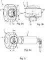
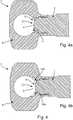
1 eine schematische Darstellung eines frontbündigen kapazitiven und/oder konduktiven Sensors gemäß Stand der Technik,2 : einen Rohradpater gemäß Stand der Technik,3 : eine mögliche Ausgestaltung eines erfindungsgemäßen Rohradapters mit zwei Ausformungen,4 : zwei Schnittdarstellungen eines Rohradapters ohne (a) und mit (b) Ausformungen zur Illustrierung des Effekts der Ausformungen,5 eine Ausgestaltung des erfindungsgemäßen Rohradapters mit einem zweiten und einem dritten Kanal,6 eine schematische Illustration des Herstellungsverfahrens mittels eines Fräsvorgangs entlang einer gedachten Leitkurve, und7 eine mögliche Ausgestaltung eines erfindungsgemäßen Rohradapters mit zwei Ausformungen und zwei Verbindungsbereichen.
1 a schematic representation of a front-flush capacitive and / or conductive sensor according to the prior art,2 : a tube adapter according to the state of the art,3 : a possible embodiment of a pipe adapter according to the invention with two formations,4th : two sectional views of a pipe adapter without (a) and with (b) formations to illustrate the effect of the formations,5 an embodiment of the pipe adapter according to the invention with a second and a third channel,6th a schematic illustration of the manufacturing process by means of a milling process along an imaginary guide curve, and7th a possible embodiment of a pipe adapter according to the invention with two formations and two connection areas.
Die vorliegende Erfindung ist auf eine Vielzahl unterschiedlicher Sensoren
Die einem kapazitiven und/oder konduktiven Messgerät, insbesondere einem Füllstandsmessgerät, zugrundeliegenden Messfahren sind an sich aus dem Stand der Technik bekannt. Entsprechende Feldgeräte werden von der Anmelderin beispielsweise unter dem Begriff LIQUIPOINT hergestellt und vertrieben. Eine schematische Darstellung eines entsprechenden Messgeräts
Die Sensoreinheit
In
Beide Kanäle
Um dieser Problematik zu umgehen, ist erfindungsgemäß in einem Übergangsbereich zwischen der Wandung des ersten
Ein Rohradapter
Es sei darauf verwiesen, dass die vorliegende Erfindung jedoch keineswegs auf Ausgestaltungen mit zwei Ausformungen
In
In
In
Abschließend sei darauf verwiesen, dass die Länge der Kanäle
BezugszeichenlisteList of reference symbols
- 11
- kapazitiver/konduktiver Sensorcapacitive / conductive sensor
- 22
- SensoreinheitSensor unit
- 33
- ElektronikeinheitElectronics unit
- 44th
- ElektrodenbaugruppeElectrode assembly
- 5a-5c5a-5c
- ElektrodenElectrodes
- 66th
- Gehäusecasing
- 6a6a
- ProzessanschlussProcess connection
- 77th
- RohradapterTube adapter
- 88th
- RohrleitungsabschnittPipe section
- 99
- ÜbergangsbereichTransition area
- 10,1 0a, 10b10.1 0a, 10b
- AusformungenFormations
- 1111
- ToträumeDead spaces
- 12,12a,12b12,12a, 12b
- Gewindethread
- 13,13a, 13b13,13a, 13b
- VerbindungsbereichConnection area
- K1,K2,K3K1, K2, K3
- Kanälechannels
- 01,02,0301.02.03
- Öffnungenopenings
- LL.
- LeitkurveGuide curve
- MM.
- Mediummedium
ZITATE ENTHALTEN IN DER BESCHREIBUNGQUOTES INCLUDED IN THE DESCRIPTION
Diese Liste der vom Anmelder aufgeführten Dokumente wurde automatisiert erzeugt und ist ausschließlich zur besseren Information des Lesers aufgenommen. Die Liste ist nicht Bestandteil der deutschen Patent- bzw. Gebrauchsmusteranmeldung. Das DPMA übernimmt keinerlei Haftung für etwaige Fehler oder Auslassungen.This list of the documents listed by the applicant was generated automatically and is included solely for the better information of the reader. The list is not part of the German patent or utility model application. The DPMA assumes no liability for any errors or omissions.
Zitierte PatentliteraturPatent literature cited
- DE 102013100158 A1 [0006]DE 102013100158 A1 [0006]
- DE 102016121643 A1 [0007]DE 102016121643 A1 [0007]
- DE 102017115139 A1 [0008]DE 102017115139 A1 [0008]
- DE 102011004807 A1 [0030]DE 102011004807 A1 [0030]
- DE 102013102055 A1 [0030]DE 102013102055 A1 [0030]
- DE 102013104781 A1 [0030]DE 102013104781 A1 [0030]
Claims (14)
Translated fromGermanPriority Applications (5)
| Application Number | Priority Date | Filing Date | Title |
|---|---|---|---|
| DE102019109787.8ADE102019109787A1 (en) | 2019-04-12 | 2019-04-12 | Hygienic pipe adapter |
| PCT/EP2020/058770WO2020207827A1 (en) | 2019-04-12 | 2020-03-27 | Hygienic tube adapter |
| EP20716415.3AEP3953665B1 (en) | 2019-04-12 | 2020-03-27 | Hygienic tube adapter |
| US17/601,478US11781696B2 (en) | 2019-04-12 | 2020-03-27 | Hygienic tube adapter |
| CN202080026043.0ACN113631895A (en) | 2019-04-12 | 2020-03-27 | Sanitary pipe adapter |
Applications Claiming Priority (1)
| Application Number | Priority Date | Filing Date | Title |
|---|---|---|---|
| DE102019109787.8ADE102019109787A1 (en) | 2019-04-12 | 2019-04-12 | Hygienic pipe adapter |
Publications (1)
| Publication Number | Publication Date |
|---|---|
| DE102019109787A1true DE102019109787A1 (en) | 2020-10-15 |
Family
ID=70154379
Family Applications (1)
| Application Number | Title | Priority Date | Filing Date |
|---|---|---|---|
| DE102019109787.8AWithdrawnDE102019109787A1 (en) | 2019-04-12 | 2019-04-12 | Hygienic pipe adapter |
Country Status (5)
| Country | Link |
|---|---|
| US (1) | US11781696B2 (en) |
| EP (1) | EP3953665B1 (en) |
| CN (1) | CN113631895A (en) |
| DE (1) | DE102019109787A1 (en) |
| WO (1) | WO2020207827A1 (en) |
Cited By (1)
| Publication number | Priority date | Publication date | Assignee | Title |
|---|---|---|---|---|
| US20220205572A1 (en)* | 2019-04-12 | 2022-06-30 | Endress+Hauser SE+Co. KG | Hygienic tube adapter |
Families Citing this family (1)
| Publication number | Priority date | Publication date | Assignee | Title |
|---|---|---|---|---|
| DE102021112752A1 (en) | 2021-05-17 | 2022-11-17 | Thomas Magnete Gmbh | Plastic part for hydraulic use in pumps or valves or valve blocks |
Citations (5)
| Publication number | Priority date | Publication date | Assignee | Title |
|---|---|---|---|---|
| US4823612A (en)* | 1986-07-10 | 1989-04-25 | Kaijo Denki Co., Ltd. | Socket structure for mounting ultrasonic gas flow measuring device with respect to gas flow pipe |
| WO1996013701A2 (en)* | 1994-10-21 | 1996-05-09 | Daniel Industries, Inc. | Apparatus for and method of draining ultrasonic transducer port cavities |
| US20030056581A1 (en)* | 1999-12-02 | 2003-03-27 | Turner William Edward | Apparatus and method for analyzing fluids |
| DE102016115426A1 (en)* | 2016-08-19 | 2018-02-22 | Endress + Hauser Wetzer Gmbh + Co. Kg | Dead-space measuring tube for a measuring device and method for its production |
| DE102017115139A1 (en)* | 2017-07-06 | 2019-01-10 | Endress+Hauser SE+Co. KG | Measuring tube and measuring tube for determining and / or monitoring at least one process variable of a medium |
Family Cites Families (22)
| Publication number | Priority date | Publication date | Assignee | Title |
|---|---|---|---|---|
| CN2118187U (en)* | 1992-04-29 | 1992-10-07 | 河北张家口市新能源设备厂 | Miniature circulating pump |
| JP3032408B2 (en)* | 1993-06-25 | 2000-04-17 | 株式会社東芝 | Electromagnetic flow meter |
| EP2911158B1 (en)* | 2002-07-31 | 2017-12-06 | Premium Genetics (UK) Limited | Method of sorting materials using holographic laser steering |
| JP4916514B2 (en)* | 2005-12-16 | 2012-04-11 | エルベ エレクトロメディジン ゲーエムベーハー | Cryosurgical instrument having a probe coupling formed from a socket and a plug of a cryogenic deep needle |
| US8016325B2 (en)* | 2006-08-30 | 2011-09-13 | Hobart Brothers Company | Self-positioning adapting system between aircraft and preconditioned-air supply hose |
| JP2009180603A (en)* | 2008-01-30 | 2009-08-13 | Toshiba Corp | measuring device |
| JP2009243922A (en)* | 2008-03-28 | 2009-10-22 | Yamatake Corp | Electromagnetic flowmeter |
| WO2009156492A1 (en)* | 2008-06-25 | 2009-12-30 | Eutec Ingenieur Gmbh | Connection arrangement for a sanitary fitting |
| GB2476954A (en)* | 2010-01-14 | 2011-07-20 | Tiss Ltd | Anti siphon device |
| DE102011004807A1 (en) | 2011-02-28 | 2012-08-30 | Endress + Hauser Gmbh + Co. Kg | probe unit |
| DE102011122268B3 (en)* | 2011-12-23 | 2013-03-21 | Promera Gmbh & Co. Kg | Method and device for dosing a fluid medium |
| ES2638857T3 (en)* | 2012-03-28 | 2017-10-24 | Abb Research Ltd. | Heat exchanger for traction converters |
| DE102013100158A1 (en) | 2012-12-21 | 2014-07-10 | Endress + Hauser Gmbh + Co. Kg | Device for determining or monitoring a process variable of a medium in a pipeline |
| DE102013102055A1 (en) | 2013-03-01 | 2014-09-18 | Endress + Hauser Gmbh + Co. Kg | Method and device for monitoring a predetermined level of a medium in a container |
| US9644496B2 (en)* | 2013-03-13 | 2017-05-09 | General Electric Company | Radial diffuser exhaust system |
| DE102013104781A1 (en) | 2013-05-08 | 2014-11-13 | Endress + Hauser Gmbh + Co. Kg | Method for monitoring at least one media-specific property of a medium |
| JP2018501458A (en)* | 2014-12-01 | 2018-01-18 | シーメンス アクチエンゲゼルシヤフトSiemens Aktiengesellschaft | Resonator with replaceable metering tubes for gas turbine engines |
| DE102015118123A1 (en)* | 2015-10-23 | 2017-04-27 | Endress+Hauser Flowtec Ag | Thermal flow meter and assembly with a tube and the thermal flow meter |
| US10018098B2 (en)* | 2016-04-14 | 2018-07-10 | Ford Global Technologies, Llc | Method and system for exhaust particulate matter sensing |
| DE102016121643A1 (en) | 2016-11-11 | 2018-05-17 | Endress+Hauser SE+Co. KG | Measuring arrangement for determining and / or monitoring at least one process variable of a medium in a pipeline |
| CN106402032B (en)* | 2016-11-25 | 2018-12-11 | 清华大学 | Inhibit the asymmetric pumping chamber of centrifugal pump and centrifugal pump of vortex and diffuser drag reduction |
| DE102019109787A1 (en)* | 2019-04-12 | 2020-10-15 | Endress+Hauser SE+Co. KG | Hygienic pipe adapter |
- 2019
- 2019-04-12DEDE102019109787.8Apatent/DE102019109787A1/ennot_activeWithdrawn
- 2020
- 2020-03-27USUS17/601,478patent/US11781696B2/enactiveActive
- 2020-03-27CNCN202080026043.0Apatent/CN113631895A/enactivePending
- 2020-03-27EPEP20716415.3Apatent/EP3953665B1/enactiveActive
- 2020-03-27WOPCT/EP2020/058770patent/WO2020207827A1/ennot_activeCeased
Patent Citations (5)
| Publication number | Priority date | Publication date | Assignee | Title |
|---|---|---|---|---|
| US4823612A (en)* | 1986-07-10 | 1989-04-25 | Kaijo Denki Co., Ltd. | Socket structure for mounting ultrasonic gas flow measuring device with respect to gas flow pipe |
| WO1996013701A2 (en)* | 1994-10-21 | 1996-05-09 | Daniel Industries, Inc. | Apparatus for and method of draining ultrasonic transducer port cavities |
| US20030056581A1 (en)* | 1999-12-02 | 2003-03-27 | Turner William Edward | Apparatus and method for analyzing fluids |
| DE102016115426A1 (en)* | 2016-08-19 | 2018-02-22 | Endress + Hauser Wetzer Gmbh + Co. Kg | Dead-space measuring tube for a measuring device and method for its production |
| DE102017115139A1 (en)* | 2017-07-06 | 2019-01-10 | Endress+Hauser SE+Co. KG | Measuring tube and measuring tube for determining and / or monitoring at least one process variable of a medium |
Cited By (2)
| Publication number | Priority date | Publication date | Assignee | Title |
|---|---|---|---|---|
| US20220205572A1 (en)* | 2019-04-12 | 2022-06-30 | Endress+Hauser SE+Co. KG | Hygienic tube adapter |
| US11781696B2 (en)* | 2019-04-12 | 2023-10-10 | Endress+Hauser SE+Co. KG | Hygienic tube adapter |
Also Published As
| Publication number | Publication date |
|---|---|
| US20220205572A1 (en) | 2022-06-30 |
| US11781696B2 (en) | 2023-10-10 |
| CN113631895A (en) | 2021-11-09 |
| WO2020207827A1 (en) | 2020-10-15 |
| EP3953665B1 (en) | 2025-06-18 |
| EP3953665A1 (en) | 2022-02-16 |
Similar Documents
| Publication | Publication Date | Title |
|---|---|---|
| DE202012013299U1 (en) | LUER CONNECTIONS | |
| EP3832291B1 (en) | Permeable measuring cell for receiving measuring means | |
| WO2009129884A1 (en) | Ultrasonic measuring arrangement | |
| DE102013100158A1 (en) | Device for determining or monitoring a process variable of a medium in a pipeline | |
| EP3649392B1 (en) | Measuring tube for detecting and/or monitoring at least one process variable of a medium | |
| DE102013110503B4 (en) | Removable sensor port insert device | |
| EP2636990A1 (en) | Measuring body of a pneumatic measuring device | |
| DE102019109787A1 (en) | Hygienic pipe adapter | |
| WO2018086888A1 (en) | Mesuring arrangement for determining and/or monitoring at least one process variable of a medium in a pipe | |
| DE102007034158A1 (en) | Method and device for the indirect measurement of the exhaustion of the filter medium of a filter | |
| EP2749335B1 (en) | Two-part particle filter | |
| DE102018129781A1 (en) | Measuring tube for a measuring device and method for its production | |
| WO2004088267A1 (en) | Pressure sensor with flame arrestor | |
| DE102013114483A1 (en) | Temperature measuring device | |
| DE3783798T2 (en) | METHOD FOR PRODUCING A CAPILLARY ELEMENT FOR USE IN AN ELECTROPHORESE DEVICE. | |
| DE60012926T2 (en) | ARRANGEMENT FOR MEASURING THE PROPERTY OF A LIQUID IN A TUBE | |
| DE102016115426A1 (en) | Dead-space measuring tube for a measuring device and method for its production | |
| DE102016213769B4 (en) | Particle filter for an exhaust system and method for producing a particle filter | |
| EP3110469B1 (en) | Medical fluid cassette and medical tube set comprising a medical fluid cassette | |
| EP4184127B1 (en) | Flow measuring device with housing and measuring insert | |
| DE3800245C2 (en) | ||
| DE102023104708A1 (en) | Fitting and method of using the fitting | |
| EP4210806B1 (en) | Luer column | |
| EP3183549B1 (en) | Method for producing a measurement tube | |
| DE102022106455A1 (en) | Sensor device and method for detecting properties of a medium |
Legal Events
| Date | Code | Title | Description |
|---|---|---|---|
| R163 | Identified publications notified | ||
| R119 | Application deemed withdrawn, or ip right lapsed, due to non-payment of renewal fee |