DE102019109262A1 - DEVICE FOR DETERMINING A STATE OF AN ULTRASONIC WELDING PROCESS - Google Patents
DEVICE FOR DETERMINING A STATE OF AN ULTRASONIC WELDING PROCESSDownload PDFInfo
- Publication number
- DE102019109262A1 DE102019109262A1DE102019109262.0ADE102019109262ADE102019109262A1DE 102019109262 A1DE102019109262 A1DE 102019109262A1DE 102019109262 ADE102019109262 ADE 102019109262ADE 102019109262 A1DE102019109262 A1DE 102019109262A1
- Authority
- DE
- Germany
- Prior art keywords
- signal
- ultrasonic
- generator
- tool
- ultrasonic tool
- Prior art date
- Legal status (The legal status is an assumption and is not a legal conclusion. Google has not performed a legal analysis and makes no representation as to the accuracy of the status listed.)
- Granted
Links
Images


Classifications
- B—PERFORMING OPERATIONS; TRANSPORTING
- B23—MACHINE TOOLS; METAL-WORKING NOT OTHERWISE PROVIDED FOR
- B23K—SOLDERING OR UNSOLDERING; WELDING; CLADDING OR PLATING BY SOLDERING OR WELDING; CUTTING BY APPLYING HEAT LOCALLY, e.g. FLAME CUTTING; WORKING BY LASER BEAM
- B23K20/00—Non-electric welding by applying impact or other pressure, with or without the application of heat, e.g. cladding or plating
- B23K20/10—Non-electric welding by applying impact or other pressure, with or without the application of heat, e.g. cladding or plating making use of vibrations, e.g. ultrasonic welding
- B23K20/106—Features related to sonotrodes
- B—PERFORMING OPERATIONS; TRANSPORTING
- B23—MACHINE TOOLS; METAL-WORKING NOT OTHERWISE PROVIDED FOR
- B23K—SOLDERING OR UNSOLDERING; WELDING; CLADDING OR PLATING BY SOLDERING OR WELDING; CUTTING BY APPLYING HEAT LOCALLY, e.g. FLAME CUTTING; WORKING BY LASER BEAM
- B23K20/00—Non-electric welding by applying impact or other pressure, with or without the application of heat, e.g. cladding or plating
- B23K20/10—Non-electric welding by applying impact or other pressure, with or without the application of heat, e.g. cladding or plating making use of vibrations, e.g. ultrasonic welding
- B—PERFORMING OPERATIONS; TRANSPORTING
- B06—GENERATING OR TRANSMITTING MECHANICAL VIBRATIONS IN GENERAL
- B06B—METHODS OR APPARATUS FOR GENERATING OR TRANSMITTING MECHANICAL VIBRATIONS OF INFRASONIC, SONIC, OR ULTRASONIC FREQUENCY, e.g. FOR PERFORMING MECHANICAL WORK IN GENERAL
- B06B1/00—Methods or apparatus for generating mechanical vibrations of infrasonic, sonic, or ultrasonic frequency
- B06B1/02—Methods or apparatus for generating mechanical vibrations of infrasonic, sonic, or ultrasonic frequency making use of electrical energy
- B06B1/0207—Driving circuits
- B06B1/0223—Driving circuits for generating signals continuous in time
- B06B1/0238—Driving circuits for generating signals continuous in time of a single frequency, e.g. a sine-wave
- B06B1/0246—Driving circuits for generating signals continuous in time of a single frequency, e.g. a sine-wave with a feedback signal
- B06B1/0253—Driving circuits for generating signals continuous in time of a single frequency, e.g. a sine-wave with a feedback signal taken directly from the generator circuit
- B—PERFORMING OPERATIONS; TRANSPORTING
- B06—GENERATING OR TRANSMITTING MECHANICAL VIBRATIONS IN GENERAL
- B06B—METHODS OR APPARATUS FOR GENERATING OR TRANSMITTING MECHANICAL VIBRATIONS OF INFRASONIC, SONIC, OR ULTRASONIC FREQUENCY, e.g. FOR PERFORMING MECHANICAL WORK IN GENERAL
- B06B1/00—Methods or apparatus for generating mechanical vibrations of infrasonic, sonic, or ultrasonic frequency
- B06B1/02—Methods or apparatus for generating mechanical vibrations of infrasonic, sonic, or ultrasonic frequency making use of electrical energy
- B06B1/06—Methods or apparatus for generating mechanical vibrations of infrasonic, sonic, or ultrasonic frequency making use of electrical energy operating with piezoelectric effect or with electrostriction
- B06B1/0607—Methods or apparatus for generating mechanical vibrations of infrasonic, sonic, or ultrasonic frequency making use of electrical energy operating with piezoelectric effect or with electrostriction using multiple elements
- B06B1/0611—Methods or apparatus for generating mechanical vibrations of infrasonic, sonic, or ultrasonic frequency making use of electrical energy operating with piezoelectric effect or with electrostriction using multiple elements in a pile
- B—PERFORMING OPERATIONS; TRANSPORTING
- B06—GENERATING OR TRANSMITTING MECHANICAL VIBRATIONS IN GENERAL
- B06B—METHODS OR APPARATUS FOR GENERATING OR TRANSMITTING MECHANICAL VIBRATIONS OF INFRASONIC, SONIC, OR ULTRASONIC FREQUENCY, e.g. FOR PERFORMING MECHANICAL WORK IN GENERAL
- B06B3/00—Methods or apparatus specially adapted for transmitting mechanical vibrations of infrasonic, sonic, or ultrasonic frequency
- B—PERFORMING OPERATIONS; TRANSPORTING
- B23—MACHINE TOOLS; METAL-WORKING NOT OTHERWISE PROVIDED FOR
- B23K—SOLDERING OR UNSOLDERING; WELDING; CLADDING OR PLATING BY SOLDERING OR WELDING; CUTTING BY APPLYING HEAT LOCALLY, e.g. FLAME CUTTING; WORKING BY LASER BEAM
- B23K31/00—Processes relevant to this subclass, specially adapted for particular articles or purposes, but not covered by only one of the preceding main groups
- B23K31/12—Processes relevant to this subclass, specially adapted for particular articles or purposes, but not covered by only one of the preceding main groups relating to investigating the properties, e.g. the weldability, of materials
- B23K31/125—Weld quality monitoring
- B—PERFORMING OPERATIONS; TRANSPORTING
- B06—GENERATING OR TRANSMITTING MECHANICAL VIBRATIONS IN GENERAL
- B06B—METHODS OR APPARATUS FOR GENERATING OR TRANSMITTING MECHANICAL VIBRATIONS OF INFRASONIC, SONIC, OR ULTRASONIC FREQUENCY, e.g. FOR PERFORMING MECHANICAL WORK IN GENERAL
- B06B2201/00—Indexing scheme associated with B06B1/0207 for details covered by B06B1/0207 but not provided for in any of its subgroups
- B06B2201/70—Specific application
- B06B2201/72—Welding, joining, soldering
- G—PHYSICS
- G01—MEASURING; TESTING
- G01R—MEASURING ELECTRIC VARIABLES; MEASURING MAGNETIC VARIABLES
- G01R27/00—Arrangements for measuring resistance, reactance, impedance, or electric characteristics derived therefrom
- G01R27/02—Measuring real or complex resistance, reactance, impedance, or other two-pole characteristics derived therefrom, e.g. time constant
- G01R27/26—Measuring inductance or capacitance; Measuring quality factor, e.g. by using the resonance method; Measuring loss factor; Measuring dielectric constants ; Measuring impedance or related variables
- G01R27/2605—Measuring capacitance
Landscapes
- Engineering & Computer Science (AREA)
- Mechanical Engineering (AREA)
- Quality & Reliability (AREA)
- Pressure Welding/Diffusion-Bonding (AREA)
- Lining Or Joining Of Plastics Or The Like (AREA)
Abstract
Translated fromGermanDescription
Translated fromGermanDie Erfindung betrifft eine Vorrichtung zum Bestimmen eines Zustands eines Ultraschallschweißprozesses, eine Anordnung und ein Verfahren.The invention relates to a device for determining a state of an ultrasonic welding process, an arrangement and a method.
Ultraschallschweißprozesse von Metallen nutzen Ultraschallwerkzeuge (oder auch US-Schwingsysteme) zum Verschweißen verschiedener Metallpaarungen. Dieser Prozess ist schnell Energieeffizient und zuverlässig.Ultrasonic welding processes of metals use ultrasonic tools (or US vibration systems) to weld different metal pairings. This process is fast, energy efficient and reliable.
Die Ultraschallschweißanlage
Ein Generator
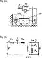
Das elektromechanische US-Schwingsystem kann als mechanisches Ersatzschaubild für den Betrieb in Resonanz dargestellt werden, siehe
Hierbei sind die Größen mit dem Index m modale Größen einer angeregten Mode. Über einen Übertrager
Somit wird aus dem Schaubild deutlich, dass eine am Piezoaktor angelegte Wechselspannung U(t) zu einer mechanischen Schwingung mit der Verschiebung x(t) führt.It is thus clear from the diagram that an alternating voltage U (t) applied to the piezo actuator leads to a mechanical oscillation with the displacement x (t).
Anstatt der mechanischen Ersatzparameter kann der Ultraschallschwinger mit einer Eigenmode auch in Form eines elektrischen Ersatzschaubilds dargestellt werden, siehe
Geht man nun davon aus, dass der Übertragungsfaktor
Industriell können die elektrischen Ersatzparameter ebenfalls zur Charakterisierung des Schwinggebildes verwendet werden.The equivalent electrical parameters can also be used industrially to characterize the oscillating structure.
Das Schwingsystem wird für den Schweißprozess wie folg genutzt: die oszillierende Bewegung der Sonotrode
Es ist eine Aufgabe der Erfindung ein vorteilhaftes Konzept zum Bestimmen eines Zustands eines Ultraschallschweißprozesses zu beschreiben.It is an object of the invention to describe an advantageous concept for determining a state of an ultrasonic welding process.
Während des Schweißprozesses gibt es verschiedene Phasen von Reinigungs-, Diffusions- und Verbindungsprozessen, die sich beispielsweise über Impedanz-, Klirrfaktor- oder Anteil bestimmter höherharmonischen Frequenzanteilsverläufe beurteilen lassen. Hieraus lassen sich Indikatoren ableiten, die zur Beurteilung der Prozessqualität genutzt werden können.During the welding process there are different phases of cleaning, diffusion and connection processes, which are assessed, for example, by means of impedance, distortion factor or the proportion of certain higher-harmonic frequency components to let. From this, indicators can be derived that can be used to assess the process quality.
Die Aufgabe wird gemäß einem ersten Aspekt durch eine Vorrichtung zum Bestimmen eines Zustands eines Ultraschallschweißprozesses gelöst, welcher mittels eines Ultraschallwerkzeugs durchführbar ist, umfassend eine Sensoreinrichtung, die eingerichtet ist, ein elektrisches Ansteuersignal des Ultraschallwerkzeugs zu erfassen; und eine Auswerteeinrichtung, die eingerichtet ist, eine Signaleigenschaft des Ansteuersignals zu ermitteln; und einen Zustand des Ultraschallschweißprozesses basierend auf einem Referenzsignalverlauf und der ermittelten Signaleigenschaft zu bestimmen.The object is achieved according to a first aspect by a device for determining a state of an ultrasonic welding process, which can be carried out by means of an ultrasonic tool, comprising a sensor device which is set up to detect an electrical control signal of the ultrasonic tool; and an evaluation device which is set up to determine a signal property of the control signal; and determine a state of the ultrasonic welding process based on a reference waveform and the determined signal property.
Der Referenzsignalverlauf kann in einem Speicher vorgespeichert sein. Die Auswerteeinheit kann eingerichtet sein, den Referenzsignalverlauf aus dem Speicher auszulesen.
Das elektrische Ansteuersignal dient der Ansteuerung des Ultraschallwerkzeugs, um den Ultraschallschweißprozess auszuführen. Durch das Ansteuersignal kann ein Generator das Ultraschallwerkzeug ansteuern.The reference signal profile can be pre-stored in a memory. The evaluation unit can be set up to read the reference signal profile from the memory.
The electrical control signal is used to control the ultrasonic tool in order to carry out the ultrasonic welding process. A generator can control the ultrasonic tool using the control signal.
Die Erfindung betrifft demnach ein systemunabhängiges Anlagen- und Prozessdiagnosesystem für Ultraschallprozesse, das Anlagenunabhängig betrieben werden kann und für den Generator aus elektrischer Sicht „unsichtbar“ ist. Dies ermöglicht sowohl eine Charakterisierung des Schwingsystems als auch eine Beurteilung des Schweißprozesses ohne in den Schweißprozess einzugreifen zu müssen und dies unabhängig vom Anlagentyp durchführen zu können.The invention accordingly relates to a system-independent plant and process diagnostic system for ultrasonic processes, which can be operated independently of the plant and is “invisible” to the generator from an electrical point of view. This enables both a characterization of the oscillation system and an assessment of the welding process without having to intervene in the welding process and being able to do this regardless of the type of system.
Eine Funktion ist die Beobachtung des Prozesses und die Erfassung der elektrischen Klemmgrößen Strom und Spannung, die am Ultraschallschwinger während der Schweißung anliegen, ohne dabei die Schweißung zu beeinflussen. Das System ist während der Schweißung für den Generator unsichtbar.One function is the observation of the process and the recording of the electrical clamp values current and voltage, which are applied to the ultrasonic transducer during the welding, without influencing the welding. The system is invisible to the generator during welding.
Die beim Messen des elektrischen Ansteuersignals gemessene Messgröße kann eine von der Zeit abhängige Variable sein. Da sich oft unter unterschiedlichen Bedingungen durchgeführte Schweißungen nicht wesentlich in ihrem Durchschnittswert oder einer einzelnen Fouriertransformation über den gesamten Schweißprozess unterscheiden, sondern nur in der Form ihrer Kurve, wenn die physikalischen Größen gegen die Zeit aufgetragen werden, ist es vorteilhaft, die Messgröße zeitabhängig zu erfassen.The measured variable measured when measuring the electrical control signal can be a time-dependent variable. Since welds carried out under different conditions often do not differ significantly in their average value or a single Fourier transformation over the entire welding process, but only in the shape of their curve, if the physical quantities are plotted against time, it is advantageous to record the measured quantity as a function of time .
Die Anwendung einer Fourieranalyse kann ein Anwenden einer Kurzzeit-Fourieranalyse umfassen, aus der die zeitliche Abhängigkeit der Amplitude, Frequenz oder anderer Größen bestimmt werden kann. Einzelne Fensterabschnitte der Kurzzeit-Fourieranalyse können auf eine geeignete Fensterfunktion zurückzugreifen, insbesondere bei der Berechnung einer Amplitude ein Flattop-Fenster, bei der Berechnung einer Frequenz oder einer Phase ein Rechteckfenster sein. Zeropadding und Interpolation können ebenso angewendet werden, insbesondere bei der Berechnung einer Frequenz bei einer Kurzzeit-Fourieranalyse mit kleinen Fenstergrößen.The use of a Fourier analysis can include the use of a short-term Fourier analysis, from which the time dependency of the amplitude, frequency or other variables can be determined. Individual window sections of the short-term Fourier analysis can make use of a suitable window function, in particular a flat-top window when calculating an amplitude, or a rectangular window when calculating a frequency or a phase. Zero padding and interpolation can also be used, particularly when calculating a frequency in a short-term Fourier analysis with small window sizes.
In einer Ausgestaltung umfasst die Vorrichtung einen ersten Anschluss, der eingerichtet ist, mit einem Ausgang eines Ultraschallgenerators verbunden zu werden; einen zweiten Anschluss, der eingerichtet ist, mit einem Signaleingang des Ultraschallwerkzeug verbunden zu werden, einen Signalpfad, der den ersten Anschluss und den zweiten Anschluss elektrisch verbindet; wobei die Sensoreinrichtung eingerichtet ist, das elektrische Ansteuersignal an dem Signalpfad nichtinvasiv zu messen.In one embodiment, the device comprises a first connection which is set up to be connected to an output of an ultrasonic generator; a second connection which is set up to be connected to a signal input of the ultrasonic tool, a signal path which electrically connects the first connection and the second connection; wherein the sensor device is set up to measure the electrical control signal on the signal path non-invasively.
Dies kann ein intelligentes Zwischenschaltsystem darstellen. Dies wird zwischen Generator und Konverter implementiert und beinhaltet Sensorik zur Strom- und Spannungsmessung.This can represent an intelligent interconnection system. This is implemented between generator and converter and contains sensors for current and voltage measurement.
In welcher Intensitätsverteilung die verschiedenen Harmonischen in einer der gemessenen Schwingungen auftreten, kann durch die Kurvenkenngrößen Klirrfaktor, Formfaktor und Scheitelfaktor beschrieben werden. Diese charakterisieren allesamt die Kurvenform einer Wechselgröße.The intensity distribution of the different harmonics in one of the measured vibrations can be described by the curve parameters distortion factor, shape factor and crest factor. These all characterize the curve shape of a variable.
Ultraschallschweißanlagen nutzen häufig die Frequenz als Stellgröße ihres Regelkreises. Diese wird derart verstellt, dass die Regelgröße konstant gehalten oder während dem Prozess gezielt verändert wird. Typische Regelgrößen sind die ins System eingebrachte Wirkleistung, Auslenkung der Sonotrode bzw. Kernadmittanz (aus den elektrischen Größen abgeschätzt) oder die Phasendifferenz zwischen Strom und Spannung. Diese Regelung ist dafür verantwortlich, dass im Beispiel der reibungsmindernden Verunreinigung durch Fette, beispielsweise Handcreme, die Betriebsfrequenz vom Generator auf einen niedrigeren Wert gestellt wird, als bei sauberen Proben. Um nachzuvollziehen, welchen Effekt bestimmte Schweißeinstellungen und Schweißbedingungen auf die Stellgröße Frequenz haben, kann man sich den Frequenzgang der Admittanz und der Kernadmittanz ansehen. Durch geringere Reibung in der Fügezone, wird die Resonanz (vom mechanischen Serienschwingkreis bestimmt) zu niedrigeren Frequenzen verschoben. Wenn der Startwert der Frequenz oberhalb der Resonanz liegt muss deshalb die Frequenz bei derartig verunreinigten Fügeteilen zu niedrigeren Werten verstellt werden als bei unpräparierten, um Auslenkung an denselben Sollwert zu regeln.Ultrasonic welding systems often use frequency as a manipulated variable in their control circuit. This is adjusted in such a way that the controlled variable is kept constant or specifically changed during the process. Typical control variables are the real power introduced into the system, deflection of the sonotrode or core admittance (estimated from the electrical variables) or the phase difference between current and voltage. This regulation is responsible for ensuring that, in the example of friction-reducing contamination by fats, for example hand cream, the operating frequency of the generator is set to a lower value than with clean samples. To understand what effect certain welding settings and welding conditions have on the manipulated variable frequency, one can look at the frequency response of the admittance and the core admittance. Due to the lower friction in the joining zone, the resonance (determined by the mechanical series oscillating circuit) is shifted to lower frequencies. If the start value of the frequency is above the resonance, the frequency must therefore be adjusted to lower values for such contaminated parts than for unprepared parts in order to control the deflection to the same setpoint.
Die Auslenkung an der Sonotrode muss beim Regeln der Anlage nicht in den Regelkreis miteinbezogen werden. Beim Regeln der Auslenkung an einen Sollwert kann diese über die elektrischen Größen abgeschätzt werden. Erfolgt zusätzlich zu den elektrischen Größen auch eine Messung der mechanischen Größen, lassen sich domänenübergreifende Größen wie die Kernadmittanz berechnen. Der Betrag der Kernadmittanz ergibt sich aus Geschwindigkeitsamplitude / Spannungsamplitude. Für die Bestimmung von dessen Phase kann eine Synchronisation der elektrischen und mechanischen Messung notwendig sein.The deflection at the sonotrode does not have to be included in the control loop when controlling the system. When regulating the deflection to a target value, this can be estimated using the electrical variables. If the mechanical quantities are also measured in addition to the electrical quantities, cross-domain quantities such as the core admittance can be calculated. The magnitude of the core admittance results from the speed amplitude / voltage amplitude. A synchronization of the electrical and mechanical measurement may be necessary to determine its phase.
In einer Ausgestaltung umfasst die Sensoreinrichtung einen Spannungsabtastkopf, um ein Spannungssignal zu messen und/oder einen Stromwandler umfasst, um ein Stromsignal zu messen.In one embodiment, the sensor device comprises a voltage scanning head in order to measure a voltage signal and / or comprises a current transformer in order to measure a current signal.
In einer Ausgestaltung umfasst die Vorrichtung ein Schaltelement, das in dem Signalpfad angeordnet ist und eingerichtet ist, den Signalpfad zu unterbrechen, um den ersten Anschluss von dem zweiten Anschluss elektrisch zu trennen, und einen Signalgeber, der eingerichtet ist, ein Steuersignal für das Ultraschallwerkzeug zu erzeugen und das Ultraschallwerkzeug anzusteuern, wenn das Schaltelement den Signalpfad unterbricht.In one configuration, the device comprises a switching element which is arranged in the signal path and is set up to interrupt the signal path in order to electrically separate the first connection from the second connection, and a signal transmitter which is set up to send a control signal for the ultrasonic tool generate and control the ultrasonic tool when the switching element interrupts the signal path.
Der Signalgeber kann eine Kleinsignal-Frequenzgeneratoreinheit mit integriertem Verstärker sein. Das Schaltelement kann ein Relais sein.The signal generator can be a small-signal frequency generator unit with an integrated amplifier. The switching element can be a relay.
Eine weitere Funktion der Vorrichtung ist, dass eine, zwischen den Schweißungen, im Ruhezustand des Schweißsystems, stattfindende Kleinsignalansteuerung des Ultraschallschwingers erfolgen kann, während der ebenfalls die elektrischen Klemmgrößen Strom und Spannung gemessen werden (Impedanzmessung). Aus der Impedanzmessung können die Ersatzparameter bestimmt und zur US-Schwinger-Charakterisierung genutzt werden. Die Kleinsignalansteuerung zur Impedanzmessung kann als modifizierte Sinuswelle (auch „Frequenzsweep“ genannt) mit einer Frequenz zwischen ± 2 kHz der Betriebsfrequenz ausgeführt sein. Während der Kleinsignalansteuerung ist der Ultraschallschwinger über eine Relais-Schaltung vom Generator entkoppelt und mit einem im Zwischenschaltsystem integrierten Verstärker gekoppelt.A further function of the device is that a small-signal control of the ultrasonic oscillator that takes place between the welds when the welding system is in the idle state can take place, during which the electrical clamp values current and voltage are also measured (impedance measurement). The substitute parameters can be determined from the impedance measurement and used for the US oscillator characterization. The small-signal control for impedance measurement can be implemented as a modified sine wave (also called “frequency sweep”) with a frequency between ± 2 kHz of the operating frequency. During the small signal control, the ultrasonic transducer is decoupled from the generator via a relay circuit and coupled to an amplifier integrated in the interconnection system.
Die direkte Analyse des Anlagenzustands erfolgt durch eine Messung des Frequenzganges der Admittanz. Hierbei wird das unbelastete Schwingsystem mit einer konstanten Spannung bei verschiedenen Frequenzen angeregt und die Systemantwort in Gestalt des Stromes (also durch einen Kleinspannungs-Sweep die frequenzabhängige Admittanz des Piezoaktors mit dem Schwingsystem als Last) gemessen. Aus dem Verhältnis von Stromantwort und Spannung resultiert die frequenzabhängige Admittanz des unbelasteten Schwingsystems. Mit diesem Frequenzgang lässt sich der Zustand des Schwingsystems charakterisieren. Da sich das Schwingsystem aus einem parallelen und einem Serienschwingkreis zusammensetzt, tritt im Bereich der Betriebsfrequenz eine Resonanz und eine Antiresonanz auf. Die Frequenzen, wo diese auftreten, deren Abstand, deren Breite und Betrag, die Phase im Frequenzbereich zwischen ihnen - all diese Größen geben Auskunft über den Zustand des Schwingsystems. Ein defekter Piezoaktor besitzt zum Beispiel einen geringeren Frequenzabstand zwischen Resonanz und eine Antiresonanz. Ein ungeeignet gelagertes System erfährt zum Beispiel Reibungsverluste, die im Frequenzgang erkennbar sind.The direct analysis of the system status is carried out by measuring the frequency response of the admittance. Here, the unloaded oscillating system is excited with a constant voltage at different frequencies and the system response is measured in the form of the current (i.e. the frequency-dependent admittance of the piezo actuator with the oscillating system as load) using a low-voltage sweep. The frequency-dependent admittance of the unloaded oscillating system results from the relationship between current response and voltage. The state of the oscillating system can be characterized with this frequency response. Since the oscillating system consists of a parallel and a series oscillating circuit, a resonance and an anti-resonance occur in the range of the operating frequency. The frequencies where they occur, their spacing, their width and magnitude, the phase in the frequency range between them - all these quantities provide information about the state of the oscillating system. A defective piezo actuator, for example, has a smaller frequency difference between resonance and anti-resonance. For example, an improperly mounted system experiences friction losses that can be seen in the frequency response.
In einer Ausgestaltung ist das Schaltelement eingerichtet, den Signalpfad zu unterbrechen, wenn die Sensorvorrichtung erfasst, dass der Ultraschallgenerator kein Steuersignal an das Ultraschallwerkzeug sendet. Somit kann in den Pausen der Ansteuerung eine weitere Messung mit dem Signalgeber als Ultraschallquelle erfolgen.In one embodiment, the switching element is set up to interrupt the signal path when the sensor device detects that the ultrasonic generator is not sending a control signal to the ultrasonic tool. Thus, during the pauses in the activation, a further measurement can be made with the signal transmitter as the ultrasonic source.
In einer Ausgestaltung ist der Signalgeber eingerichtet, das Steuersignal für das Ultraschallwerkzeug mittels einer Kleinsignalsteuerung zu erzeugen. Die Berechnung der notwendigen Parameter kann mittels einer Kleinsignalsteuerung vereinfacht erfolgen.In one embodiment, the signal transmitter is set up to generate the control signal for the ultrasonic tool by means of a small-signal controller. The necessary parameters can be calculated in a simplified manner by means of a small-signal control.
In einer Ausgestaltung ist die Sensorvorrichtung eingerichtet, ein elektrisches Signal an dem Signalpfad zu messen, während der Signalgeber der Vorrichtung über den Signalpfad das Ultraschallwerkzeug ansteuert. Dies kann zur Gewinnung eines Referenzverlaufs beitragen, da der Signalgeber vordefinierte Werte bereitstellen kann.In one embodiment, the sensor device is set up to measure an electrical signal on the signal path, while the signal transmitter of the device controls the ultrasonic tool via the signal path. This can help to obtain a reference curve, since the signal generator can provide predefined values.
In einer Ausgestaltung ist die Auswertevorrichtung eingerichtet, basierend auf dem gemessenen elektrischen Signal, das gemessen wurde, während der Signalgeber der Vorrichtung über den Signalpfad das Ultraschallwerkzeug ansteuert, Ersatzparameter zu bestimmen. Dies kann eine Aktualisierung des Modells mittels der Kleinsignalsteuerung bewirken.In one embodiment, the evaluation device is set up to determine substitute parameters based on the measured electrical signal that was measured while the signal transmitter of the device controls the ultrasonic tool via the signal path. This can bring about an update of the model by means of the small-signal control.
Das Schwingsystem lässt sich durch ein elektromechanisches Ersatzschaltbild modellieren. Durch Vergleich der Systemantwort dieses Ersatzschaltbildes mit dem gemessenen Frequenzgang lassen sich die Ersatzparameter des Schaltbildes bestimmen. Mit einem Modell aus vier Ersatzparametern kann der Frequenzgang von Ultraschallschweißanlagen sehr gut approximiert werden. Die Parameter sind: Kapazität des Piezoaktors, Kapazität, Induktivität und Widerstand des mechanischen Schwingers (hier werden die mechanischen Parameter Trägheit, Steifigkeit und Dämpfung in die analogen elektrischen Parameter Kapazität, Induktivität und Widerstand umgewandelt, wie sie in die Impedanz eingehen, die die Last des Generators beschreibt). Mit diesem Verfahren sind Veränderungen des Schwingsystems, vor allem schleichende Veränderungen des Piezoaktors detektierbar.The oscillation system can be modeled using an electromechanical equivalent circuit diagram. By comparing the system response of this equivalent circuit diagram with the measured frequency response, the equivalent parameters of the circuit diagram can be determined. With a model consisting of four substitute parameters, the frequency response of ultrasonic welding systems can be approximated very well. The parameters are: capacitance of the piezo actuator, capacitance, inductance and resistance of the mechanical oscillator (here the mechanical parameters Inertia, stiffness and damping are converted into the analog electrical parameters of capacity, inductance and resistance as they go into the impedance, which describes the load of the generator). With this method, changes in the oscillation system, especially creeping changes in the piezo actuator, can be detected.
Es kann auch eine Berechnung dieser Ersatzparameter für den Fall eines belasteten Schwingsystems erfolgen, d.h. wenn die Sonotrode mit einer Normalkraft auf die Fügeteile gepresst wird und damit zusätzliche Dämpfung erfährt. Es ist auch möglich, einen Frequenzgang während des Schweißprozesses zu messen, indem die anregende Spannung deutlich kleiner als die Schweißspannung, die sich im kilo-Volt-Bereich befindet, ist, und damit den Schweißprozess nicht stört, sondern nur überlagert. Sofern die momentane Frequenz der Frequenzgangmessung nicht zu nahe bei der momentanen Betriebsfrequenz ist, lässt sich bei der Strommessung der Anteil der momentanen Frequenz der Frequenzgangmessung herausfiltern. Hierbei kann sich die Auswerteeinrichtung einer Fourieranalyse bedienen.These substitute parameters can also be calculated for the case of a loaded oscillating system, i.e. when the sonotrode is pressed onto the joining parts with a normal force and thus experiences additional damping. It is also possible to measure a frequency response during the welding process in which the exciting voltage is significantly lower than the welding voltage, which is in the kilo-volt range, and therefore does not interfere with the welding process, but only superimposes it. If the current frequency of the frequency response measurement is not too close to the current operating frequency, the portion of the current frequency of the frequency response measurement can be filtered out during the current measurement. Here, the evaluation device can use a Fourier analysis.
In einer Ausgestaltung ist der Signalgeber eingerichtet, das Steuersignal basierend auf einem Betriebssignal des Ultraschallgenerators zu erzeugen, insbesondere mit einer Frequenz zwischen ± 2 kHz der Betriebsfrequenz des Ultraschallgenerators.In one embodiment, the signal generator is set up to generate the control signal based on an operating signal of the ultrasonic generator, in particular at a frequency between ± 2 kHz of the operating frequency of the ultrasonic generator.
In einer Ausgestaltung umfasst die Vorrichtung ein Entladungsschaltelement, das an dem Signalpfad elektrisch angeschlossen und eingerichtet ist, in einem leitenden Zustand das Ultraschallwerkzeug kurzzuschließen, so dass eine Restladung im Ultraschallwerkzeug abfließen kann.In one embodiment, the device comprises a discharge switching element which is electrically connected to the signal path and is set up to short-circuit the ultrasonic tool in a conductive state so that a residual charge in the ultrasonic tool can flow away.
Gemäß einem zweiten Aspekt wird die Aufgabe durch Anordnung mit einer Ultraschallschweißanlage und einer Vorrichtung nach dem ersten Aspekt gelöst, wobei die Vorrichtung zwischen einem Ultraschallgenerator der Ultraschallschweißanlage und einem Konverter der Ultraschallschweißanlage angeschlossen ist.According to a second aspect, the object is achieved by an arrangement with an ultrasonic welding system and a device according to the first aspect, the device being connected between an ultrasonic generator of the ultrasonic welding system and a converter of the ultrasonic welding system.
Gemäß einem dritten Aspekt wird die Aufgabe durch ein Verfahren zum Bestimmen eines Zustands eines Ultraschallschweißprozesses gelöst, umfassend:
- Messen eines elektrischen Ansteuersignals eines Ultraschallwerkzeugs durch eine Sensoreinrichtung; und
- Ermitteln einer Signaleigenschaft des Ansteuersignals durch eine Auswerteeinrichtung; und
- Bestimmen eines Zustands des Ultraschallschweißprozesses basierend auf einem Referenzsignalverlauf und der ermittelten Signaleigenschaft durch die Auswerteeinrichtung.
- Measuring an electrical control signal of an ultrasonic tool by a sensor device; and
- Determining a signal property of the control signal by an evaluation device; and
- Determination of a state of the ultrasonic welding process based on a reference signal curve and the determined signal property by the evaluation device.
In einer Ausgestaltung wird wobei das Messen während eines Schweißprozesses ausgeführt. Dies kann eine Überwachung des Schweißprozesses ermöglichen.In one embodiment, the measurement is carried out during a welding process. This can enable the welding process to be monitored.
In einer Ausgestaltung umfasst das Verfahren ein Trennen eines Ultraschallgenerators von dem Ultraschallwerkzeug durch ein Schaltelement.In one embodiment, the method comprises separating an ultrasonic generator from the ultrasonic tool by means of a switching element.
In einer Ausgestaltung umfasst das Verfahren ein Erzeugen eines Steuersignals durch einen Signalgeber und Ansteuern des Ultraschallwerkzeugs, wenn der Ultraschallgenerator von dem Ultraschallwerkzeug getrennt ist.In one embodiment, the method comprises generating a control signal by a signal transmitter and activating the ultrasonic tool when the ultrasonic generator is separated from the ultrasonic tool.
In einer Ausgestaltung umfasst das Verfahren ein Bestimmen eines Ersatzparameters für die Schweißanlage basierend auf einem bestimmten Zustand des Ultraschallschweißprozesses basierend auf dem erzeugten Steuersignal.In one configuration, the method includes determining a substitute parameter for the welding system based on a specific state of the ultrasonic welding process based on the control signal generated.
Auf diese Weise können Referenzwerte zur Bestimmung der gemessenen Kurven erzeugt werden und ein Modell verbessert werden, nach dem der Signalgeber und die Auswerteeinrichtung arbeiten.In this way, reference values for determining the measured curves can be generated and a model can be improved, according to which the signal transmitter and the evaluation device work.
Die Erfindung wird im Folgenden anhand von Figuren und Ausführungsbeispielen näher beschrieben. Es zeigen:
1 eine schematische Darstellung einer Ultraschallschweißanlage;2a ein mechanisches Ersatzschaltbild einer Ultraschallschweißanlage;2b ein elektrisches Ersatzschaltbild des mechanisches Ersatzschaltbilds aus2a ;2c ein elektrisches Kleinsignalersatzschaltbild des mechanisches Ersatzschaltbilds aus2a ;3 eine schematische Darstellung einer Ultraschallschweißanlage gemäß einem Ausführungsbeispiel; und4 ein Flussdiagramm für ein Verfahren gemäß einem Ausführungsbeispiel.
1 a schematic representation of an ultrasonic welding system;2a a mechanical equivalent circuit diagram of an ultrasonic welding system;2 B an electrical equivalent circuit diagram of the mechanical equivalent circuit diagram2a ;2c an electrical small-signal equivalent circuit diagram of the mechanical equivalent circuit diagram2a ;3 a schematic representation of an ultrasonic welding system according to an embodiment; and4th a flow chart for a method according to an embodiment.
Die direkte Analyse erfordert eine Vorrichtung
Über ein Relais
Durch die Relaisschaltung kann entweder der Ultraschallgenerator
In einem weiteren Ausführungsbeispiel kann das Schwingsystem zwischen den Schaltvorgängen, die das Schwingsystem mit dem Ultraschallgenerator
Die Relaisschaltung sowie der modifizierte Sinus werden softwareseitig angesteuert bzw. erzeugt. Die Zeitpunkte für die Schaltung der jeweiligen Schaltelemente
Beginnt die Schweißung, wird ein Trigger aktiviert, und die Software erkennt Start und Ende der Schweißung und speichert die gemessenen Spannungs- und Stromverläufe für die anschließende Auswertung. Nach abgeschlossener Schweißung wird die Prozesspause genutzt und die Software schaltet von „Generator-Ultraschallschwinger“ über „Kurzschluss-Ultraschallschwinger“ zu „Kleinsignal-Ultraschallschwinger“. Das heißt, das Schaltelement
Nun wird der modifizierte Sinus durch den Signalgeber
Die Umschaltung und Auswertung findet in einer Auswerteeinrichtung
In einem ersten Schritt
In einem zweiten Schritt
In einem Schritt
In one
In Schritt
In Schritt
Parallel hierzu wird im Schritt
In Schritt
BezugszeichenlisteList of reference symbols
- 100100
- UltraschallschweißanlageUltrasonic welding system
- 101101
- Generatorgenerator
- 103103
- SchwingerzeugerVibrator
- 105105
- SonotrodeSonotrode
- 107107
- SchweißgutWeld metal
- 201201
- Wagendare
- 202202
- UmgebungSurroundings
- 300300
- UltraschallschweißanlageUltrasonic welding system
- 301301
- UltraschallgeneratorUltrasonic generator
- 303303
- UltraschallwerkzeugUltrasonic tool
- 305305
- Vorrichtungcontraption
- 307307
- SchaltelementSwitching element
- 309309
- Relaisrelay
- 311311
- SignalgeberSignal transmitter
- 313313
- EntladungsschaltelementDischarge switching element
- 315315
- AuswerteeinheitEvaluation unit
- 316316
- SensoreinrichtungSensor device
- 317317
- SpannungsmesserVoltmeter
- 319319
- StromwandlerPower converter
- 400400
- Flussdiagrammflow chart
- 401-407401-407
- VerfahrensschrittProcess step
- mmmm
- MasseDimensions
- cmcm
- Federfeather
- dmdm
- Dämpfermute
- FF.
- Kraftforce
- xx
- Verschiebungshift
- aa
- ÜbertragerTransformer
- CpCp
- Kapazitätcapacity
- RpRp
- VerlustwiderstandLoss resistance
- UU
- Spannungtension
- Ladungcharge
- ii
- mechanische Schwingungmechanical vibration
Claims (15)
Translated fromGermanPriority Applications (5)
| Application Number | Priority Date | Filing Date | Title |
|---|---|---|---|
| DE102019109262.0ADE102019109262A1 (en) | 2019-04-09 | 2019-04-09 | DEVICE FOR DETERMINING A STATE OF AN ULTRASONIC WELDING PROCESS |
| CN202080027294.0ACN113677473B (en) | 2019-04-09 | 2020-03-31 | Device for determining the state of an ultrasonic welding process |
| EP20716446.8AEP3953096B1 (en) | 2019-04-09 | 2020-03-31 | Device and method for determining a status of an ultrasonic welding process |
| PCT/EP2020/059137WO2020207863A1 (en) | 2019-04-09 | 2020-03-31 | Device for determining a status of an ultrasonic welding process |
| US17/497,513US11969817B2 (en) | 2019-04-09 | 2021-10-08 | Device for determining a status of an ultrasonic welding process |
Applications Claiming Priority (1)
| Application Number | Priority Date | Filing Date | Title |
|---|---|---|---|
| DE102019109262.0ADE102019109262A1 (en) | 2019-04-09 | 2019-04-09 | DEVICE FOR DETERMINING A STATE OF AN ULTRASONIC WELDING PROCESS |
Publications (1)
| Publication Number | Publication Date |
|---|---|
| DE102019109262A1true DE102019109262A1 (en) | 2020-10-15 |
Family
ID=70154407
Family Applications (1)
| Application Number | Title | Priority Date | Filing Date |
|---|---|---|---|
| DE102019109262.0AGrantedDE102019109262A1 (en) | 2019-04-09 | 2019-04-09 | DEVICE FOR DETERMINING A STATE OF AN ULTRASONIC WELDING PROCESS |
Country Status (5)
| Country | Link |
|---|---|
| US (1) | US11969817B2 (en) |
| EP (1) | EP3953096B1 (en) |
| CN (1) | CN113677473B (en) |
| DE (1) | DE102019109262A1 (en) |
| WO (1) | WO2020207863A1 (en) |
Cited By (1)
| Publication number | Priority date | Publication date | Assignee | Title |
|---|---|---|---|---|
| US20220023967A1 (en)* | 2019-04-09 | 2022-01-27 | Lisa Draexlmaier Gmbh | Device for determining a status of an ultrasonic welding process |
Citations (5)
| Publication number | Priority date | Publication date | Assignee | Title |
|---|---|---|---|---|
| DE4206584C2 (en)* | 1992-03-03 | 1994-03-10 | Fraunhofer Ges Forschung | Device and method for connecting two components by means of ultrasound |
| DE4321874A1 (en)* | 1993-07-01 | 1995-01-12 | Ver Foerderung Inst Kunststoff | Process and device for the open-loop and closed-loop control of process parameters in ultrasonic welding |
| DE10110048A1 (en)* | 2001-03-02 | 2002-09-05 | Bosch Gmbh Robert | Method for testing connections made by ultrasonic wire bonding |
| DE102013225643A1 (en)* | 2013-12-11 | 2015-06-11 | Robert Bosch Gmbh | Method for contactless functional testing of a signal converter |
| DE102014116474A1 (en)* | 2014-11-11 | 2016-05-12 | Herrmann Ultraschalltechnik Gmbh & Co. Kg | Ultrasonic processing system with piezoelectric force sensor |
Family Cites Families (33)
| Publication number | Priority date | Publication date | Assignee | Title |
|---|---|---|---|---|
| JP2725116B2 (en)* | 1992-07-21 | 1998-03-09 | 株式会社カイジョー | Wire bonding apparatus and method |
| DE4233929A1 (en)* | 1992-10-09 | 1994-04-14 | Kln Ultraschall Gmbh | Device for connecting components by vibration welding |
| JP3370553B2 (en)* | 1997-05-07 | 2003-01-27 | 株式会社新川 | Bonding load correction method and wire bonding apparatus |
| JP3176580B2 (en)* | 1998-04-09 | 2001-06-18 | 太陽誘電株式会社 | Electronic component mounting method and mounting device |
| US6039234A (en)* | 1998-06-16 | 2000-03-21 | Kulicke & Soffa Investments, Inc. | Missing wire detector |
| US6236017B1 (en)* | 1999-07-01 | 2001-05-22 | Bechtel Bwxt Idaho, Llc | Method and apparatus for assessing weld quality |
| JP3566166B2 (en)* | 2000-02-10 | 2004-09-15 | 株式会社新川 | Tool position measuring method, offset measuring method, reference member and bonding device |
| DE10046451A1 (en)* | 2000-09-18 | 2002-03-28 | Spaichingen Gmbh Maschf | Method and device for ultrasonic welding of workpieces |
| US6667625B1 (en)* | 2001-12-31 | 2003-12-23 | Charles F. Miller | Method and apparatus for detecting wire in an ultrasonic bonding tool |
| JP2004047944A (en)* | 2002-05-22 | 2004-02-12 | Nec Corp | Bonding apparatus and bonding method having process for judging bonding state |
| DE102004026826B4 (en)* | 2004-05-28 | 2010-01-14 | Schunk Ultraschalltechnik Gmbh | Ultrasonic welding device and converter of an ultrasonic welding device |
| DE102005030777B4 (en)* | 2005-07-01 | 2016-10-20 | Martin Walter Ultraschalltechnik Ag | Method and circuit arrangement for operating an ultrasonic vibrator |
| US20070084539A1 (en)* | 2005-10-14 | 2007-04-19 | Norbert Junker | Quick change device for the oscillating tool of a vibration welding machine |
| US9486955B2 (en)* | 2006-05-08 | 2016-11-08 | Dukane Ias, Llc | Ultrasonic press using servo motor with delayed motion |
| US7819013B2 (en)* | 2006-07-05 | 2010-10-26 | The Hong Kong Polytechnic University | Method and apparatus for measuring oscillation amplitude of an ultrasonic device |
| JP4786500B2 (en)* | 2006-10-26 | 2011-10-05 | 株式会社東芝 | Wire bonding apparatus and wire bonding method |
| DE102007054626A1 (en)* | 2007-11-12 | 2009-05-14 | Hesse & Knipps Gmbh | Method and apparatus for ultrasonic bonding |
| DE102008029769A1 (en)* | 2008-06-25 | 2009-12-31 | Sonotronic Nagel Gmbh | Sonotrode tool for ultrasonic welding, has internal cooling system in sonotrode body to accelerate cooling and reduce residence time of sonotrode on workpiece |
| DE102009003312A1 (en)* | 2008-10-14 | 2010-04-15 | Hesse & Knipps Gmbh | Bonding device, ultrasonic transducer and bonding method |
| CN101574757B (en)* | 2009-05-01 | 2013-05-22 | 台州巨龙超声设备有限公司 | Control system of ultrasonic welding machine |
| US7845543B1 (en)* | 2009-11-17 | 2010-12-07 | Asm Assembly Automation Ltd | Apparatus and method for bonding multiple dice |
| DE102012215994A1 (en)* | 2012-09-10 | 2014-03-13 | Weber Ultrasonics Gmbh | Method and circuit arrangement for determining a working range of an ultrasound oscillating structure |
| DE102012109037B4 (en)* | 2012-09-25 | 2020-11-26 | Adolf Würth Gmbh & Co Kg | Ultrasonic generator with low pass on the output side for a hand-held device |
| DE102013222876B4 (en)* | 2012-11-16 | 2018-03-29 | GM Global Technology Operations LLC (n. d. Gesetzen des Staates Delaware) | Vibration welding system with automatic monitoring |
| TWI517277B (en)* | 2014-02-14 | 2016-01-11 | 新川股份有限公司 | Wire bonding device and manufacturing method of semiconductor device |
| US9889521B2 (en)* | 2014-12-02 | 2018-02-13 | Asm Technology Singapore Pte Ltd | Method and system for pull testing of wire bonds |
| JP5950994B2 (en)* | 2014-12-26 | 2016-07-13 | 株式会社新川 | Mounting device |
| CN106271036B (en)* | 2016-08-12 | 2018-09-14 | 广州市精源电子设备有限公司 | Ultrasonic wave metal welding quality appraisal procedure, device and ultrasonic metal bonding machine |
| DE102017122684A1 (en)* | 2017-09-29 | 2019-04-04 | Lisa Dräxlmaier GmbH | TEST APPARATUS AND TEST METHOD FOR CHECKING A DATA CABLE FOR A POWER VEHICLE THROUGH CONSTANT CURRENT SOURCE |
| CN108247192A (en)* | 2018-02-06 | 2018-07-06 | 南京航空航天大学 | A kind of Double-linkage clamps metal foil ultrasound firm joint device |
| DE102019106694A1 (en)* | 2019-03-15 | 2020-09-17 | Herrmann Ultraschalltechnik Gmbh & Co. Kg | Method for the detection of a sonotrode coming into or out of contact with a counter-element |
| DE102019109263B4 (en)* | 2019-04-09 | 2021-11-18 | Lisa Dräxlmaier GmbH | Method, a measuring device and an ultrasonic welding system for non-destructive testing of the quality of an ultrasonic weld |
| DE102019109262A1 (en)* | 2019-04-09 | 2020-10-15 | Lisa Dräxlmaier GmbH | DEVICE FOR DETERMINING A STATE OF AN ULTRASONIC WELDING PROCESS |
- 2019
- 2019-04-09DEDE102019109262.0Apatent/DE102019109262A1/enactiveGranted
- 2020
- 2020-03-31WOPCT/EP2020/059137patent/WO2020207863A1/ennot_activeCeased
- 2020-03-31EPEP20716446.8Apatent/EP3953096B1/enactiveActive
- 2020-03-31CNCN202080027294.0Apatent/CN113677473B/enactiveActive
- 2021
- 2021-10-08USUS17/497,513patent/US11969817B2/enactiveActive
Patent Citations (5)
| Publication number | Priority date | Publication date | Assignee | Title |
|---|---|---|---|---|
| DE4206584C2 (en)* | 1992-03-03 | 1994-03-10 | Fraunhofer Ges Forschung | Device and method for connecting two components by means of ultrasound |
| DE4321874A1 (en)* | 1993-07-01 | 1995-01-12 | Ver Foerderung Inst Kunststoff | Process and device for the open-loop and closed-loop control of process parameters in ultrasonic welding |
| DE10110048A1 (en)* | 2001-03-02 | 2002-09-05 | Bosch Gmbh Robert | Method for testing connections made by ultrasonic wire bonding |
| DE102013225643A1 (en)* | 2013-12-11 | 2015-06-11 | Robert Bosch Gmbh | Method for contactless functional testing of a signal converter |
| DE102014116474A1 (en)* | 2014-11-11 | 2016-05-12 | Herrmann Ultraschalltechnik Gmbh & Co. Kg | Ultrasonic processing system with piezoelectric force sensor |
Cited By (2)
| Publication number | Priority date | Publication date | Assignee | Title |
|---|---|---|---|---|
| US20220023967A1 (en)* | 2019-04-09 | 2022-01-27 | Lisa Draexlmaier Gmbh | Device for determining a status of an ultrasonic welding process |
| US11969817B2 (en)* | 2019-04-09 | 2024-04-30 | Lisa Draexlmaier Gmbh | Device for determining a status of an ultrasonic welding process |
Also Published As
| Publication number | Publication date |
|---|---|
| WO2020207863A1 (en) | 2020-10-15 |
| CN113677473B (en) | 2024-02-13 |
| CN113677473A (en) | 2021-11-19 |
| US11969817B2 (en) | 2024-04-30 |
| EP3953096B1 (en) | 2024-05-08 |
| EP3953096A1 (en) | 2022-02-16 |
| US20220023967A1 (en) | 2022-01-27 |
Similar Documents
| Publication | Publication Date | Title |
|---|---|---|
| DE102019109263B4 (en) | Method, a measuring device and an ultrasonic welding system for non-destructive testing of the quality of an ultrasonic weld | |
| DE102017112307A1 (en) | METHOD AND DEVICE FOR EVALUATING AN ULTRASONIC WELDING CONNECTION | |
| WO2017005918A1 (en) | Method and device for measuring a resonance frequency of a tool ultrasonically vibrated for machining | |
| EP2892660B1 (en) | Method and circuit system for determining a working range of an ultrasonic vibrating unit | |
| DE2316598B2 (en) | Method and device for determining a welded connection between workpieces connected with an ultrasonic device | |
| DE102017108392A1 (en) | METHOD AND DEVICE FOR EVALUATING AN ULTRASONIC WELDING CONNECTION | |
| DE102010008298A1 (en) | Horn with part determination | |
| DE102020112851A1 (en) | Control device for an electric drive unit of an ophthalmic surgical handpiece and method for its operation, ophthalmic surgical device and system | |
| EP2057960B1 (en) | Dental ultrasound device and method for operating a dental ultrasound device | |
| EP3953096B1 (en) | Device and method for determining a status of an ultrasonic welding process | |
| DE102019106694A1 (en) | Method for the detection of a sonotrode coming into or out of contact with a counter-element | |
| EP4390388A1 (en) | Method for checking the quality of at least one ultrasonic weld connection, measuring device and computer program | |
| WO2014048712A2 (en) | Communication device for an ultrasonic appliance, and method for operating such an appliance | |
| WO2020011594A1 (en) | Method for operating an electrosurgical system and ultrasound generator | |
| DE102007013055B4 (en) | Method and device for determining the frequency characteristic and for operating an ultrasonic tool | |
| WO2024094730A1 (en) | Ultrasonic welding method with joining partner feedback, and device therefor | |
| DE102007053460A1 (en) | Method for operating a dental ultrasound device and dental ultrasound device | |
| EP4004567B1 (en) | Method and generator for characterizing an oscillatory system | |
| DE2823361A1 (en) | MONITORING OF ULTRASONIC AND SOUND DEVICES | |
| DE102017101736A1 (en) | Method of making wire bonds and device for carrying out the method | |
| DE102021112809B4 (en) | Positioning device and method for operating such a positioning device for predicting defects | |
| DE102006016359B4 (en) | Method for controlling an ultrasonic unit of an ultrasonic cleaning system and ultrasonic cleaning system | |
| DE102005030764B4 (en) | Method and device for switching on an ultrasonic vibration system | |
| DE102021102100A1 (en) | Method and device for testing objects intended for ultrasonic welding | |
| DE102011108134B4 (en) | Method for operating an ultrasound device and protective circuit for such |
Legal Events
| Date | Code | Title | Description |
|---|---|---|---|
| R012 | Request for examination validly filed | ||
| R016 | Response to examination communication | ||
| R016 | Response to examination communication | ||
| R016 | Response to examination communication | ||
| R018 | Grant decision by examination section/examining division |