DE102019106334A1 - Means of transport and user interface for an autonomously drivable means of transport - Google Patents
Means of transport and user interface for an autonomously drivable means of transportDownload PDFInfo
- Publication number
- DE102019106334A1 DE102019106334A1DE102019106334.5ADE102019106334ADE102019106334A1DE 102019106334 A1DE102019106334 A1DE 102019106334A1DE 102019106334 ADE102019106334 ADE 102019106334ADE 102019106334 A1DE102019106334 A1DE 102019106334A1
- Authority
- DE
- Germany
- Prior art keywords
- steering wheel
- wheel rim
- user interface
- impact pot
- impact
- Prior art date
- Legal status (The legal status is an assumption and is not a legal conclusion. Google has not performed a legal analysis and makes no representation as to the accuracy of the status listed.)
- Pending
Links
- 230000033001locomotionEffects0.000claimsabstractdescription36
- 238000006073displacement reactionMethods0.000claimsdescription13
- 238000000034methodMethods0.000claimsdescription3
- 230000008569processEffects0.000claimsdescription2
- 239000006096absorbing agentSubstances0.000description7
- 230000007704transitionEffects0.000description5
- 230000003247decreasing effectEffects0.000description2
- 239000012530fluidSubstances0.000description2
- 230000004308accommodationEffects0.000description1
- 230000004888barrier functionEffects0.000description1
- 230000008859changeEffects0.000description1
- 230000008878couplingEffects0.000description1
- 238000010168coupling processMethods0.000description1
- 238000005859coupling reactionMethods0.000description1
- 230000006378damageEffects0.000description1
- 238000001514detection methodMethods0.000description1
- 238000011161developmentMethods0.000description1
- 230000018109developmental processEffects0.000description1
- 230000000694effectsEffects0.000description1
- 238000005516engineering processMethods0.000description1
- 238000009434installationMethods0.000description1
- 239000000725suspensionSubstances0.000description1
Images


Classifications
- B—PERFORMING OPERATIONS; TRANSPORTING
- B62—LAND VEHICLES FOR TRAVELLING OTHERWISE THAN ON RAILS
- B62D—MOTOR VEHICLES; TRAILERS
- B62D1/00—Steering controls, i.e. means for initiating a change of direction of the vehicle
- B62D1/02—Steering controls, i.e. means for initiating a change of direction of the vehicle vehicle-mounted
- B62D1/04—Hand wheels
- B62D1/10—Hubs; Connecting hubs to steering columns, e.g. adjustable
- B62D1/105—Non-rotatable hubs, e.g. the central part of the steering wheel not rotating
- B—PERFORMING OPERATIONS; TRANSPORTING
- B60—VEHICLES IN GENERAL
- B60N—SEATS SPECIALLY ADAPTED FOR VEHICLES; VEHICLE PASSENGER ACCOMMODATION NOT OTHERWISE PROVIDED FOR
- B60N3/00—Arrangements or adaptations of other passenger fittings, not otherwise provided for
- B60N3/001—Arrangements or adaptations of other passenger fittings, not otherwise provided for of tables or trays
- B60N3/002—Arrangements or adaptations of other passenger fittings, not otherwise provided for of tables or trays of trays
- B60N3/005—Arrangements or adaptations of other passenger fittings, not otherwise provided for of tables or trays of trays mounted on the steering wheel
- B—PERFORMING OPERATIONS; TRANSPORTING
- B62—LAND VEHICLES FOR TRAVELLING OTHERWISE THAN ON RAILS
- B62D—MOTOR VEHICLES; TRAILERS
- B62D1/00—Steering controls, i.e. means for initiating a change of direction of the vehicle
- B62D1/02—Steering controls, i.e. means for initiating a change of direction of the vehicle vehicle-mounted
- B62D1/16—Steering columns
- B62D1/18—Steering columns yieldable or adjustable, e.g. tiltable
- B62D1/183—Steering columns yieldable or adjustable, e.g. tiltable adjustable between in-use and out-of-use positions, e.g. to improve access
- B—PERFORMING OPERATIONS; TRANSPORTING
- B62—LAND VEHICLES FOR TRAVELLING OTHERWISE THAN ON RAILS
- B62D—MOTOR VEHICLES; TRAILERS
- B62D1/00—Steering controls, i.e. means for initiating a change of direction of the vehicle
- B62D1/02—Steering controls, i.e. means for initiating a change of direction of the vehicle vehicle-mounted
- B62D1/04—Hand wheels
- B62D1/046—Adaptations on rotatable parts of the steering wheel for accommodation of switches
- B—PERFORMING OPERATIONS; TRANSPORTING
- B62—LAND VEHICLES FOR TRAVELLING OTHERWISE THAN ON RAILS
- B62D—MOTOR VEHICLES; TRAILERS
- B62D1/00—Steering controls, i.e. means for initiating a change of direction of the vehicle
- B62D1/02—Steering controls, i.e. means for initiating a change of direction of the vehicle vehicle-mounted
- B62D1/16—Steering columns
- B62D1/18—Steering columns yieldable or adjustable, e.g. tiltable
- B62D1/181—Steering columns yieldable or adjustable, e.g. tiltable with power actuated adjustment, e.g. with position memory
Landscapes
- Engineering & Computer Science (AREA)
- Transportation (AREA)
- Mechanical Engineering (AREA)
- Chemical & Material Sciences (AREA)
- Combustion & Propulsion (AREA)
- Steering Controls (AREA)
Abstract
Translated fromGermanDescription
Translated fromGermanDie vorliegende Erfindung betrifft ein Fortbewegungsmittel sowie eine Anwenderschnittstelle für ein Level
Früher war das Lenkrad rein zum Lenken gedacht. Mit der Zeit haben sich immer mehr Funktionen im Lenkrad positioniert (unter anderem der Airbag, die Hupe oder das Ändern der Lautstärke des Entertainmentsystems). Auch die Funktionen, die man zusätzlich integrieren kann, sind hinsichtlich Übersichtlichkeit und Platz begrenzt. Dadurch, dass das ganze Lenkrad für Lenkbewegungen beweglich ist, können Anzeigen und/oder Bedienelemente im/am Lenkrad nicht beliebig angeordnet werden, da in Abhängigkeit des Lenkeinschlages nicht gewährleistet ist, dass diese in jeder Position abgelesen bzw. bedient werden können. Des Weiteren wird beim hochautomatisierten Fahren („Ease-Modus“) das Lenkrad teilweise überflüssig. In der Zeit, in der das Fahrzeug die Fahraufgabe komplett übernimmt, kann der Fahrer anderen Aktivitäten nachgehen. Mit der aktuellen Bauweise des Lenkrades wird dieses beispielsweise beim Arbeiten am Laptop im Weg sein.In the past, the steering wheel was intended purely for steering. Over time, more and more functions have been positioned in the steering wheel (including the airbag, the horn or changing the volume of the entertainment system). The functions that can also be integrated are limited in terms of clarity and space. Because the entire steering wheel is movable for steering movements, displays and / or operating elements in / on the steering wheel cannot be arranged as desired, since depending on the steering angle it is not guaranteed that they can be read or operated in every position. Furthermore, with highly automated driving ("Ease mode"), the steering wheel is sometimes superfluous. While the vehicle is fully taking over the driving task, the driver can pursue other activities. With the current design of the steering wheel, it will be in the way when working on a laptop, for example.
Bereits 1971 schuf Giorgetto Giugiaro mit seiner Studie für Maserati „Boomerang“ ein Lenkrad mit feststehender Nabe und im Lenkradkranz angeordneten Anzeige- und Bedienelementen (https://en.wikipedia.org/wiki/Maserati_Boomerang).https://www.all-electronics.de/lenkrad-mit-feststehender-nabe/ offenbart ein Fortbewegungsmittel mit feststehender Nabe, sodass der Frontalairbag für den Fahrer eine von einer runden Form abweichende Gestalt annehmen kann. Zusätzlich bietet das Konzept einer feststehenden Nabe verbesserten Komfort für den Fahrer und ermöglicht größere Designfreiheit für den Fahrzeughersteller. Anzeigen und Bedienelemente können auf dem Lenkrad untergebracht werden, statt dicht an dicht auf bereits überladenen Instrumententafeln angeordnet zu sein.Already in 1971 Giorgetto Giugiaro created with his study for Maserati "Boomerang" a steering wheel with a fixed hub and display and control elements arranged in the steering wheel rim (https://en.wikipedia.org/wiki/Maserati_Boomerang).https://www.all-electronics.de/lenkrad-mit-feststehender-nabe/ discloses a means of transport with a fixed hub so that the frontal airbag for the driver can take on a shape that deviates from a round shape. In addition, the concept of a fixed hub offers improved comfort for the driver and allows greater design freedom for the vehicle manufacturer. Displays and controls can be placed on the steering wheel instead of being arranged close together on already cluttered instrument panels.
Ausgehend vom vorgenannten Stand der Technik ist es eine Aufgabe der vorliegenden Erfindung, die Ausgestaltung eines Fahrerarbeitsplatzes sowohl für den manuellen als auch für den automatischen Fahrmodus ergonomisch und funktionell auszugestalten.Based on the aforementioned prior art, it is an object of the present invention to make the configuration of a driver's workstation ergonomic and functional both for the manual and for the automatic driving mode.
Die vorgenannte Aufgabe wird erfindungsgemäß durch eine Anwenderschnittstelle für ein Level
Die Unteransprüche zeigen bevorzugte Weiterbildungen der Erfindung.The subclaims show preferred developments of the invention.
Der Lenkradkranz selbst kann einstückig und/oder flexibel ausgeführt sein. Insbesondere ist der Lenkradkranz nicht teilbar oder in sich klappbar ausgeführt. Der Lenkradkranz erhält hierdurch eine hohe Steifigkeit und eine für den Anwender vertrauenserweckende Haptik. Ein unverformbares Lenkrad bzw. ein unverformbarer Lenkradkranz bietet hinsichtlich der Übertragung von Lenkbewegungen des Anwenders auf die Räder eine größtmögliche Zuverlässigkeit.The steering wheel rim itself can be made in one piece and / or flexible. In particular, the steering wheel rim is not designed to be divisible or foldable. This gives the steering wheel rim a high degree of rigidity and a feel that inspires confidence for the user. A non-deformable steering wheel or a non-deformable steering wheel rim offers the greatest possible reliability with regard to the transfer of the user's steering movements to the wheels.
Der Pralltopf kann eingerichtet sein, nicht ausschließlich zur Lenksäulenverstellung im Sinne einer Erhöhung der Bedienergonomie beim Ausführen von Lenkbewegungen eine Linearverschiebung auszuführen. Hierbei kann der Pralltopf in eine Position verbracht werden, in welcher er nicht mit dem Lenkradkranz während dessen Schwenkbewegung kollidiert, während der Pralltopf in seiner ursprünglichen Position während der Ausführung der Schwenkbewegung mit dem Lenkradkranz kollidieren würde. Die Linearverschiebung kann beim Verbringen des Pralltopfes aus der Konfiguration für das manuelle Fahren (Level 1 bis 3) in die Konfiguration für das automatische Fahren (Level 4 oder 5) insbesondere in Richtung der Fahrzeugfront gerichtet sein, und somit räumlich und logisch vollständig in die Instrumententafel integriert werden. Hierbei wird im Unterschied zu einer herkömmlichen Lenksäulenverstellung (s.o.) durch den Pralltopf eine Linearverschiebung bevorzugt unabhängig von einer Linearverschiebung des Lenkradkranzes ausgeführt. Auf diese Weise entfernt sich der Pralltopf vom Anwender und verschafft diesem Bewegungsfreiheit, Crashsicherheit und kann sich bestmöglich in das Armaturenbrett bzw. die Fahrgastzellenarchitektur einfügen.The impact pot can be set up not to carry out a linear displacement exclusively for the steering column adjustment in the sense of increasing the operator ergonomics when carrying out steering movements. Here, the impact pot can be brought into a position in which it does not collide with the steering wheel rim during its pivoting movement, while the impact pot would collide with the steering wheel rim in its original position during the execution of the pivoting movement. The linear displacement can be changed when moving the impact pot from the configuration for manual driving (level 1 to 3) into the configuration for automatic driving (
Bevorzugt ist der Pralltopf eingerichtet, im Zuge einer Schwenkung des Lenkradkranzes zwangsläufig die Linearverschiebung auszuführen. Insbesondere kann die Zwangskopplung beider Bewegungen mechanisch vorgegeben sein. Mit noch anderen Worten ist eine Verschwenkung des Lenkradkranzes unabhängig von einer Linearverschiebung des Pralltopfes nicht möglich. Somit kann zuverlässig verhindert werden, dass der Lenkradkranz mit dem Pralltopf und den gegebenenfalls auf diesem angeordneten Bedienelementen kollidiert und eine Kollision mit den Fingern oder einer Hand des Nutzers beim Bedien- oder Auslösevorgang vermieden werden.The impact pot is preferably set up to inevitably carry out the linear displacement in the course of a pivoting of the steering wheel rim. In particular, the forced coupling of both movements can be specified mechanically. In other words, it is not possible to pivot the steering wheel rim independently of a linear displacement of the impact pot. This can reliably prevent the steering wheel rim from colliding with the impact absorber and the operating elements possibly arranged on it and avoiding a collision with the fingers or a hand of the user during the operating or triggering process.
Eine lenksäulenseitige Kontur bzw. Oberfläche des Pralltopfes (sozusagen seine Rückseite) kann zu einer Kontur eines Armaturenbrettes des Fortbewegungsmittels korrespondierend ausgestaltet sein. Mit anderen Worten kann in der Konfiguration des Fahrerarbeitsplatzes für das Level 4-Fahren eine Kavität in der Fahrgastzellenbegrenzung (Armaturenbrett) des Fortbewegungsmittels durch den Pralltopf gefüllt werden. Hierdurch schmiegt sich der Pralltopf besonders formschön und crashsicher in die Innenraumbegrenzung der Fahrgastzelle ein. Insbesondere können hierbei die Bedienelemente, welche auf dem Pralltopf angeordnet sein können, logisch in die gegebenenfalls im Armaturenbrett angeordneten weiteren Bedienelemente eingefügt werden. Mit anderen Worten können zwischen dem Pralltopf und dem Armaturenbrett lediglich schmale Spalte verbleiben, sobald der Pralltopf in die Konfiguration für das Level 4-Fahren gebracht worden ist.A contour or surface of the impact absorber on the steering column side (its rear side, so to speak) can be configured to correspond to a contour of a dashboard of the means of locomotion. In other words, in the configuration of the driver's workplace for
Um zu vermeiden, dass der sich allmählich verringernde Spalt zwischen dem Pralltopf und dem Armaturenbrett Verletzungen hervorrufen kann, kann ein Sensor am Fahrerarbeitsplatz bzw. an der Anwenderschnittstelle vorgesehen sein, welcher einen Einklemmschutz zwischen dem Pralltopf und dem Armaturenbrett bereitstellt. Dieser Sensor kann beispielsweise optisch, kapazitiv, mechanisch oder magnetisch arbeiten. Er kann als Wegsensor ausgestaltet sein und im Falle seines Ansprechens einen sofortigen Stopp der Linearbewegung des Pralltopfes bewirken. Alternativ oder zusätzlich kann eine Warnung an den Anwender/die Insassen des Fortbewegungsmittels ausgegeben werden. Alternativ oder zusätzlich kann der Pralltopf ein Stück weit in Richtung seiner ursprünglichen Position zurückweichen, um gegebenenfalls eingeklemmte Objekte/Personen freizugeben.In order to avoid that the gradually decreasing gap between the impact pot and the dashboard can cause injuries, a sensor can be provided at the driver's workplace or at the user interface, which provides protection against trapping between the impact pot and the dashboard. This sensor can work optically, capacitively, mechanically or magnetically, for example. It can be designed as a displacement sensor and, if it responds, cause the linear movement of the impact pot to stop immediately. Alternatively or additionally, a warning can be output to the user / occupants of the means of transport. As an alternative or in addition, the impact pot can move back a little in the direction of its original position in order to release any objects / people that are jammed.
Der Lenkradkranz kann insbesondere eingerichtet sein, um eine horizontale, vom Pralltopf ausgehend in positiver X-Richtung gelegene Achse geschwenkt zu werden. Die Achse kann hierbei insbesondere in Y-Richtung verlaufen. Sämtliche im Rahmen der vorliegenden Offenbarung genannten Richtungen beziehen sich auf das Fahrzeugkoordinatensystem (X: Fahrzeuglängsrichtung, Y: Fahrzeugquerrichtung, Z: Vertikale). Hierbei wird der Lenkradkranz zunächst in Richtung des Fahrerarbeitsplatzes/des Fahrers gekippt und kann insbesondere nach ungefähr einer Schwenkbewegung von 90° in Richtung der Fahrzeugfront verschoben werden. Dies schließt nicht aus, dass der Lenkradkranz im Wesentlichen parallel zur Längserstreckung der Längssäule verschoben wird. Auf diese Weise kann der Lenkradkranz weitestmöglich vom Fahrer entfernt ruhen, ohne den Fußraum des Fahrerarbeitsplatzes unnötig einzunehmen. Andererseits ist der Lenkradkranz in ergonomischer Höhe angeordnet und kann vom Anwender (anteilig) auch in einem autonomen Fahrmodus ergriffen oder gar optisch erfasst werden. Der Lenkradkranz kann eingerichtet sein, eine im Wesentlichen parallel zur Längssäule orientierte Position einzunehmen. Mit anderen Worten ist eine durch den Lenkradkranz definierte Fläche im Wesentlichen parallel zur Längssäule angeordnet, wenn der Lenkradkranz in die Position für das autonome Fahren geschwenkt ist. Insbesondere kann das Schwenken derart erfolgen, dass ein momentan zuoberst gelegener Teil des Lenkradkranzes zunächst in Richtung des Fahrers geschwenkt wird (negative X-Richtung) und hierbei in zunehmendem Maße abgesenkt wird (negative Z-Richtung). Hingegen wird ein momentan zuunterst gelegener Teil des Lenkradkranzes unmittelbar in Richtung der Lenksäule (positive X-Richtung, gegebenenfalls positive Z-Richtung) geschwenkt. Auf diese Weise nimmt der Lenkradkranz minimalen Fußraum ein oder lässt sich gar vollständig im Armaturenbrett unterbringen. Das Schwenken des Lenkradkranzes um die Y-Achse verkürzt insbesondere die Linearbewegung der Lenkradkranz-Pralltopf-Kombination in x-Richtung, was eine reduziertere Linearverschiebung und damit einen kürzeren Bauraum in x-Richtung bedingt.The steering wheel rim can in particular be designed to be pivoted around a horizontal axis, starting from the impact pot, in the positive X direction. The axis can in particular run in the Y direction. All directions mentioned in the context of the present disclosure relate to the vehicle coordinate system (X: vehicle longitudinal direction, Y: vehicle transverse direction, Z: vertical). Here, the steering wheel rim is first tilted in the direction of the driver's workstation / driver and can be moved in the direction of the front of the vehicle after approximately a pivoting movement of 90 °. This does not rule out that the steering wheel rim is shifted essentially parallel to the longitudinal extension of the longitudinal column. In this way, the steering wheel rim can rest as far away from the driver as possible without unnecessarily occupying the footwell of the driver's workplace. On the other hand, the steering wheel rim is arranged at an ergonomic height and can be grasped by the user (partially) in an autonomous driving mode or even visually detected. The steering wheel rim can be designed to assume a position oriented essentially parallel to the longitudinal column. In other words, a surface defined by the steering wheel rim is arranged essentially parallel to the longitudinal column when the steering wheel rim is pivoted into the position for autonomous driving. In particular, the pivoting can take place in such a way that a part of the steering wheel rim that is currently at the top is initially pivoted in the direction of the driver (negative X direction) and is lowered to an increasing extent (negative Z direction). In contrast, a part of the steering wheel rim that is currently located at the bottom is pivoted directly in the direction of the steering column (positive X direction, possibly positive Z direction). In this way, the steering wheel rim takes up minimal foot space or can even be fully accommodated in the dashboard. The pivoting of the steering wheel rim about the Y-axis shortens, in particular, the linear movement of the steering wheel rim-impact absorber combination in the x-direction, which results in a reduced linear displacement and thus a shorter installation space in the x-direction.
Bevorzugt kann vorgesehen sein, dass der Lenkradkranz in einer vordefinierten Rotationslage (z. B. entsprechend einer Geradeausfahrt) angeordnet sein muss, damit er in erfindungsgemäßer Weise schwenkfähig ist. Mit anderen Worten kann eine mechanische und/oder elektrische und/oder logische Barriere das Schwenken des Lenkradkranzes verhindern, sofern die vordefinierte Rotationslage nicht besteht. Auf diese Weise kann verhindert werden, dass bei der Wiederaufnahme der manuellen Fahrzeugführung unerwartete Lenkzustände hergestellt werden.It can preferably be provided that the steering wheel rim must be arranged in a predefined rotational position (e.g. corresponding to driving straight ahead) so that it can pivot in the manner according to the invention. In other words, a mechanical and / or electrical and / or logical barrier can prevent the steering wheel rim from pivoting if the predefined rotational position is not consists. In this way it can be prevented that unexpected steering states are established when manual vehicle driving is resumed.
Der Pralltopf kann eine Anwenderschnittstelle aufweisen, welche sowohl im manuellen als auch im automatisierten Fahrmodus für den Anwender zur Verfügung steht. Hierbei können Ausgaben und insbesondere auch Eingaben mittels der Anwenderschnittstelle im Pralltopf erfolgen. Insbesondere kann der obere Teil des Pralltopfes eine horizontale Anzeigefläche enthalten, in der fahrrelevante Informationen angezeigt werden können (z.B. Geschwindigkeit, Warnhinweise, Check-Control Meldungen etc.). Beispielsweise kann der Pralltopf ein berührungsempfindliches Eingabeelement (z. B. ein Touchscreen, mehrere berührungsempfindliche/berührungssensitive Bedienflächen und/oder Eingabeelemente) und/oder mechanische Schalter, Räder, Digitiser o. Ä. aufweisen. Dies schließt nicht aus, dass die Anwenderschnittstelle bzw. der durch sie verfügbare Funktionsumfang im manuellen Fahrmodus ein anderer als im automatisierten Fahrmodus ist. Der Funktionsumfang kann auf die jeweils verfügbaren Funktionen abgestimmt sein. Beispielsweise kann eine logische Gliederung der Anwenderschnittstelle derart umgesetzt werden, dass in einem ersten Bereich (z. B. links am Pralltopf) die für die Fahrzeugführung relevanten Informationen und/oder Eingabeelemente angeordnet sind, während in einem zweiten Bereich (z.B. rechts am Pralltopf) die für die Anzeige und Bedienung der Infotainmentumfänge vorgesehenen Anzeige-/Bedienelemente angeordnet sind.The impact pot can have a user interface which is available to the user in both manual and automated driving mode. Outputs and, in particular, inputs can be made in the impact pot by means of the user interface. In particular, the upper part of the impact absorber can contain a horizontal display area in which information relevant to the journey can be displayed (e.g. speed, warning notices, check control messages, etc.). For example, the impact pot can have a touch-sensitive input element (for example a touchscreen, several touch-sensitive / touch-sensitive operating surfaces and / or input elements) and / or mechanical switches, wheels, digitsers or the like. exhibit. This does not rule out that the user interface or the range of functions available through it is different in manual driving mode than in automated driving mode. The range of functions can be tailored to the available functions. For example, a logical structure of the user interface can be implemented in such a way that the information and / or input elements relevant for driving the vehicle are arranged in a first area (e.g. on the left on the impact pot), while in a second area (e.g. on the right on the impact pot) the for the display and operation of the infotainment features provided display / control elements are arranged.
Insbesondere können in einem automatisierten Fahrmodus die der Fahrzeugführung zugeordneten Eingabeelemente (anteilig) durch andere Bedienelemente ersetzt werden bzw. mit anderen Funktionen belegt werden. Insbesondere können Komfort-/Unterhaltungsfunktionen auf Bedienelemente/Anzeigeelemente gelegt werden, welche an derjenigen Stelle angeordnet sind, an welcher zuvor die zur Fahrzeugführung vorgesehenen Anzeige-/Bedienelemente angeordnet waren.In particular, in an automated driving mode, the input elements assigned to driving the vehicle can be (partially) replaced by other operating elements or assigned other functions. In particular, comfort / entertainment functions can be placed on operating elements / display elements which are arranged at the point at which the display / operating elements provided for driving the vehicle were previously arranged.
Des Weiteren können an den Seitenflächen rechts und links am Pralltopf weitere Bedienelemente angebracht werden, die sich somit nicht auf der dem Fahrer zugewandten Fläche, sondern rechts und links am Pralltopf in positiver X-Achse etwas vom Fahrer entfernt befinden. So können sich fahrgewohnheitsgemäß die Bedienung der Lichthupe sowie der Richtungsanzeiger auf einem Bedienelement auf der linken Seite, die Bedienelemente der Scheibenwischer- und Wischwasserpumpe auf der rechten Seite des Pralltopfes wiederfinden. Durch das oben beschriebene Verfahren zur Linearverschiebung des Pralltopfes in Richtung des Armaturenbrettes beim Übergang vom manuellen zum autonomen Fahren, wobei die zusätzlichen Bedienelemente hinderlich wären, können diese in dafür vorgesehene Aussparungen in den Seitenflächen rechts und links am Pralltopf eingefahren werden. Dies ist außerdem vorteilhaft, da die mit diesen Bedienelementen verbundenen Funktionen im autonomen Fahrmodus nicht mehr länger bedienbar und damit sichtbar sein müssen. Beim Übergang vom autonomen zum manuellen Fahrmodus werden die zusätzlichen Bedienelemente durch die Linearverschiebung des Pralltopfes in negative X-Achse wieder ausgefahren und damit wieder sichtbar und bedienbar.Furthermore, further control elements can be attached to the right and left of the impact pot on the side surfaces, which are therefore not located on the surface facing the driver, but on the right and left of the impact pot in the positive X-axis slightly away from the driver. As usual, the operation of the headlight flasher and the direction indicator can be found on a control element on the left-hand side and the control elements for the windshield wiper and washer fluid pump on the right-hand side of the impact pot. The above-described method for linear displacement of the impact pot in the direction of the dashboard during the transition from manual to autonomous driving, whereby the additional controls would be a hindrance, can be retracted into the recesses provided in the side surfaces on the right and left of the impact pot. This is also advantageous since the functions associated with these operating elements no longer have to be operable and therefore visible in the autonomous driving mode. When changing from the autonomous to the manual driving mode, the additional control elements are extended again by the linear displacement of the impact pot in the negative X-axis and are thus visible and operable again.
Gemäß einem zweiten Aspekt der vorliegenden Erfindung wird ein Fortbewegungsmittel (z. B. ein Pkw, Motorrad, Transporter, Lkw, Luft- und/oder Wasserfahrzeug) vorgesehen sein, welches eine Anwenderschnittstelle gemäß dem erstgenannten Erfindungsaspekt aufweist. Die Merkmale, Merkmalskombinationen und die sich aus diesen ergebenen Vorteile des Fortbewegungsmittels ergeben sich derart ersichtlich in zur Anwenderschnittstelle entsprechender Weise, dass zur Vermeidung von Wiederholungen auf die obigen Ausführungen verwiesen wird.According to a second aspect of the present invention, a means of locomotion (e.g. a car, motorcycle, van, truck, aircraft and / or watercraft) is provided which has a user interface according to the first-mentioned aspect of the invention. The features, feature combinations and the advantages of the means of locomotion resulting from these are evident in a manner corresponding to the user interface that reference is made to the above statements to avoid repetition.
Weitere Einzelheiten, Merkmale und Vorteile der Erfindung ergeben sich aus der nachfolgenden Beschreibung und den Figuren. Es zeigen:
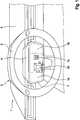
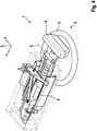
1 eine perspektivische Darstellung eines Fahrerarbeitsplatzes eines ersten Ausführungsbeispiels in einer Konfiguration für das manuelle Führen des Fortbewegungsmittels;2 eine perspektivische Darstellung eines Fahrerarbeitsplatzes eines ersten Ausführungsbeispiels in einer Konfiguration für das automatisierte Führen des Fortbewegungsmittels;3 eine perspektivische Detailansicht eines zweiten Ausführungsbeispiels einer erfindungsgemäßen Anwenderschnittstelle in einer Konfiguration für das manuelle Führen des Fortbewegungsmittels;4 eine perspektivische Detailansicht eines zweiten Ausführungsbeispiels einer erfindungsgemäßen Anwenderschnittstelle in einer Konfiguration für das automatisierte Führen des Fortbewegungsmittels;5 eine perspektivische Detailansicht eines dritten Ausführungsbeispiels einer erfindungsgemäßen Anwenderschnittstelle in einem Zwischenzustand;6 eine detaillierte Draufsicht auf ein viertes Ausführungsbeispiel einer erfindungsgemäßen Anwenderschnittstelle in einem ersten Zwischenzustand;7 eine detaillierte Draufsicht auf ein viertes Ausführungsbeispiel einer erfindungsgemäßen Anwenderschnittstelle in einem zweiten Zwischenzustand;8 eine detaillierte Draufsicht auf ein viertes Ausführungsbeispiel einer erfindungsgemäßen Anwenderschnittstelle in einer Konfiguration für das automatisierte Führen des Fortbewegungsmittels;9 eine Frontalansicht eines Ausführungsbeispiels eines Pralltopfes eines erfindungsgemäßen Lenkrades; und10 eine perspektivische Ansicht eines Ausführungsbeispiels eines Pralltopfes eines erfindungsgemäßen Lenkrades.
1 a perspective view of a driver's workplace of a first embodiment in a configuration for manual guidance of the means of locomotion;2 a perspective view of a driver's workplace of a first embodiment in a configuration for the automated guidance of the means of locomotion;3 a perspective detailed view of a second embodiment of a user interface according to the invention in a configuration for the manual guidance of the means of locomotion;4th a perspective detailed view of a second embodiment of a user interface according to the invention in a configuration for the automated guidance of the means of locomotion;5 a perspective detailed view of a third embodiment of a user interface according to the invention in an intermediate state;6th a detailed plan view of a fourth embodiment of a user interface according to the invention in a first intermediate state;7th a detailed plan view of a fourth embodiment of an inventive User interface in a second intermediate state;8th a detailed plan view of a fourth embodiment of a user interface according to the invention in a configuration for the automated guidance of the means of locomotion;9 a front view of an embodiment of an impact pot of a steering wheel according to the invention; and10 a perspective view of an embodiment of an impact pot of a steering wheel according to the invention.
BezugszeichenlisteList of reference symbols
- 11
- AnwenderschnittstelleUser interface
- 22
- Lenkradsteering wheel
- 33
- LenkradkranzSteering wheel rim
- 44th
- PralltopfImpact pot
- 55
- Armaturenbrettdashboard
- 66th
- LenksäuleSteering column
- 77th
- AnwenderschnittstelleUser interface
- 7 a, b7 a, b
- TouchscreenTouch screen
- 7 c7 c
- Mechanischer SchalterMechanical switch
- 7 d7 d
- FingerabdrucksensorFingerprint sensor
- 7e, f7e, f
- BedienhebelControl lever
- 88th
- SchwenkachseSwivel axis
- XX
- FahrzeuglängsrichtungVehicle longitudinal direction
- YY
- FahrzeugquerrichtungVehicle transverse direction
- ZZ
- Vertikalevertical
Claims (11)
Translated fromGermanPriority Applications (1)
| Application Number | Priority Date | Filing Date | Title |
|---|---|---|---|
| DE102019106334.5ADE102019106334A1 (en) | 2019-03-13 | 2019-03-13 | Means of transport and user interface for an autonomously drivable means of transport |
Applications Claiming Priority (1)
| Application Number | Priority Date | Filing Date | Title |
|---|---|---|---|
| DE102019106334.5ADE102019106334A1 (en) | 2019-03-13 | 2019-03-13 | Means of transport and user interface for an autonomously drivable means of transport |
Publications (1)
| Publication Number | Publication Date |
|---|---|
| DE102019106334A1true DE102019106334A1 (en) | 2020-09-17 |
Family
ID=72289359
Family Applications (1)
| Application Number | Title | Priority Date | Filing Date |
|---|---|---|---|
| DE102019106334.5APendingDE102019106334A1 (en) | 2019-03-13 | 2019-03-13 | Means of transport and user interface for an autonomously drivable means of transport |
Country Status (1)
| Country | Link |
|---|---|
| DE (1) | DE102019106334A1 (en) |
Cited By (7)
| Publication number | Priority date | Publication date | Assignee | Title |
|---|---|---|---|---|
| CN113562061A (en)* | 2020-04-29 | 2021-10-29 | 株式会社万都 | Steering column with folding steering wheel structure |
| US20210362667A1 (en)* | 2020-05-22 | 2021-11-25 | Hyundai Mobis Co., Ltd. | Steering wheel module for vehicle |
| US11230315B2 (en)* | 2020-01-24 | 2022-01-25 | Joyson Safety Systems Acquisition Llc | Foldable steering wheel |
| US11247713B2 (en)* | 2018-04-04 | 2022-02-15 | Jtekt Corporation | Steering apparatus |
| DE102020133726A1 (en) | 2020-12-16 | 2022-06-23 | Bayerische Motoren Werke Aktiengesellschaft | Steering assembly for a vehicle, steering input device for a steering assembly, vehicle and method for operating a vehicle with a steering assembly |
| DE102021108609A1 (en) | 2021-04-07 | 2022-10-13 | Schaeffler Technologies AG & Co. KG | Steer-by-wire steering system |
| DE102024117862B3 (en) | 2024-06-25 | 2025-02-27 | Bayerische Motoren Werke Aktiengesellschaft | steering device of a vehicle with a steering wheel |
Citations (6)
| Publication number | Priority date | Publication date | Assignee | Title |
|---|---|---|---|---|
| US2622690A (en)* | 1949-02-25 | 1952-12-23 | Barenyi Bela | Steering device for motor vehicles |
| US20140277896A1 (en)* | 2013-03-15 | 2014-09-18 | Audi Ag | Dual-state steering wheel/input device |
| DE102016015254A1 (en)* | 2016-12-21 | 2017-05-24 | Daimler Ag | Vehicle with a steering device |
| DE102017107817A1 (en)* | 2016-05-25 | 2017-11-30 | Ford Global Technologies, Llc | STEERING WHEEL ASSEMBLY |
| WO2018052708A1 (en)* | 2016-09-19 | 2018-03-22 | Fca Us Llc | Stowable steering wheel assembly |
| GB2559880A (en)* | 2017-01-16 | 2018-08-22 | Jaguar Land Rover Ltd | Steering Wheel Assembly |
- 2019
- 2019-03-13DEDE102019106334.5Apatent/DE102019106334A1/enactivePending
Patent Citations (6)
| Publication number | Priority date | Publication date | Assignee | Title |
|---|---|---|---|---|
| US2622690A (en)* | 1949-02-25 | 1952-12-23 | Barenyi Bela | Steering device for motor vehicles |
| US20140277896A1 (en)* | 2013-03-15 | 2014-09-18 | Audi Ag | Dual-state steering wheel/input device |
| DE102017107817A1 (en)* | 2016-05-25 | 2017-11-30 | Ford Global Technologies, Llc | STEERING WHEEL ASSEMBLY |
| WO2018052708A1 (en)* | 2016-09-19 | 2018-03-22 | Fca Us Llc | Stowable steering wheel assembly |
| DE102016015254A1 (en)* | 2016-12-21 | 2017-05-24 | Daimler Ag | Vehicle with a steering device |
| GB2559880A (en)* | 2017-01-16 | 2018-08-22 | Jaguar Land Rover Ltd | Steering Wheel Assembly |
Cited By (9)
| Publication number | Priority date | Publication date | Assignee | Title |
|---|---|---|---|---|
| US11247713B2 (en)* | 2018-04-04 | 2022-02-15 | Jtekt Corporation | Steering apparatus |
| US11230315B2 (en)* | 2020-01-24 | 2022-01-25 | Joyson Safety Systems Acquisition Llc | Foldable steering wheel |
| CN113562061A (en)* | 2020-04-29 | 2021-10-29 | 株式会社万都 | Steering column with folding steering wheel structure |
| DE102021204312B4 (en) | 2020-04-29 | 2023-09-07 | Hl Mando Corporation | STEERING COLUMN WITH FOLDABLE STEERING WHEEL STRUCTURE |
| US20210362667A1 (en)* | 2020-05-22 | 2021-11-25 | Hyundai Mobis Co., Ltd. | Steering wheel module for vehicle |
| US11648903B2 (en)* | 2020-05-22 | 2023-05-16 | Hyundai Mobis Co., Ltd. | Steering wheel module for vehicle |
| DE102020133726A1 (en) | 2020-12-16 | 2022-06-23 | Bayerische Motoren Werke Aktiengesellschaft | Steering assembly for a vehicle, steering input device for a steering assembly, vehicle and method for operating a vehicle with a steering assembly |
| DE102021108609A1 (en) | 2021-04-07 | 2022-10-13 | Schaeffler Technologies AG & Co. KG | Steer-by-wire steering system |
| DE102024117862B3 (en) | 2024-06-25 | 2025-02-27 | Bayerische Motoren Werke Aktiengesellschaft | steering device of a vehicle with a steering wheel |
Similar Documents
| Publication | Publication Date | Title |
|---|---|---|
| DE102019106334A1 (en) | Means of transport and user interface for an autonomously drivable means of transport | |
| EP3393856B1 (en) | Motor vehicle with a control panel module | |
| DE102018123181A1 (en) | Multipurpose dashboard for use in a vehicle | |
| EP3823855B1 (en) | Motor vehicle comprising an instrument panel and method for operating a motor vehicle | |
| EP3067244B1 (en) | Motor vehicle with automatic situation adaptive drive mode | |
| EP3519236B1 (en) | Assembly, means of transportation and method for assisting a user of a means of transportation | |
| DE102013202427B4 (en) | Motor vehicle with an adjustment device arranged in the footwell and method for controlling the longitudinal movement of a motor vehicle | |
| DE102013003214A1 (en) | Method for transferring driving tasks between occupants e.g. driver of motor car, involves terminating autonomous driving by driving assistance system after detecting completed transfer and acquisition of object by other occupant | |
| WO2019030198A1 (en) | DISPLAYS FOR A MOTOR VEHICLE AND MOTOR VEHICLE WITH SUCH A SCREEN ARRANGEMENT | |
| DE10137971A1 (en) | Motor vehicle with a steering wheel that can be moved in the direction of the dashboard | |
| DE102015011646A1 (en) | Motor vehicle with multi-part touch-sensitive screen device | |
| EP1747964B1 (en) | Operating element with mini lever | |
| WO2013057201A1 (en) | Method for assisting a driver by means of a driver assistance device | |
| EP2695792B1 (en) | Device with a steering handle and a control panel and motor vehicle | |
| DE102017011975A1 (en) | Display device for a motor vehicle | |
| DE102013019113A1 (en) | Motor vehicle with touch screen holding device | |
| EP3188922B1 (en) | Control device and method for controlling functions in a vehicle, in particular a motor vehicle | |
| DE102021127913A1 (en) | Method for adjusting a seat of a motor vehicle and motor vehicle | |
| DE102016224844A1 (en) | User interface, means of locomotion and method for the manual control of a highly automated mobile means of transport | |
| DE102018110137B4 (en) | Interior component for a motor vehicle | |
| DE102014112896B4 (en) | Industrial truck with a display and control device | |
| EP2889446A1 (en) | Tailgate of a vehicle, grip module for such a tailgate and corresponding vehicle | |
| EP3369697A1 (en) | Industrial truck | |
| DE102018109840A1 (en) | Device and method for operating a computer of a motor vehicle, in particular of an automobile | |
| DE102024000948A1 (en) | Operating device of a motor vehicle and motor vehicle |
Legal Events
| Date | Code | Title | Description |
|---|---|---|---|
| R163 | Identified publications notified | ||
| R012 | Request for examination validly filed |