DE102018222413A1 - Hand tool with at least one safety brake device - Google Patents
Hand tool with at least one safety brake deviceDownload PDFInfo
- Publication number
- DE102018222413A1 DE102018222413A1DE102018222413.7ADE102018222413ADE102018222413A1DE 102018222413 A1DE102018222413 A1DE 102018222413A1DE 102018222413 ADE102018222413 ADE 102018222413ADE 102018222413 A1DE102018222413 A1DE 102018222413A1
- Authority
- DE
- Germany
- Prior art keywords
- tool
- brake device
- safety brake
- circular saw
- hand
- Prior art date
- Legal status (The legal status is an assumption and is not a legal conclusion. Google has not performed a legal analysis and makes no representation as to the accuracy of the status listed.)
- Pending
Links
- 239000006260foamSubstances0.000claimsdescription3
- 229910052782aluminiumInorganic materials0.000claimsdescription2
- XAGFODPZIPBFFR-UHFFFAOYSA-NaluminiumChemical compound[Al]XAGFODPZIPBFFR-UHFFFAOYSA-N0.000claimsdescription2
- 239000006262metallic foamSubstances0.000claims1
- 239000000126substanceSubstances0.000claims1
- 230000001960triggered effectEffects0.000claims1
- 238000003754machiningMethods0.000abstractdescription14
- 238000001514detection methodMethods0.000description5
- 230000006378damageEffects0.000description3
- 238000002595magnetic resonance imagingMethods0.000description2
- 229910052751metalInorganic materials0.000description2
- 239000002184metalSubstances0.000description2
- 230000005540biological transmissionEffects0.000description1
- 230000000903blocking effectEffects0.000description1
- 239000002131composite materialSubstances0.000description1
- 238000011161developmentMethods0.000description1
- 230000018109developmental processEffects0.000description1
- 230000000694effectsEffects0.000description1
- 238000004146energy storageMethods0.000description1
- 230000006698inductionEffects0.000description1
Images

Classifications
- B—PERFORMING OPERATIONS; TRANSPORTING
- B27—WORKING OR PRESERVING WOOD OR SIMILAR MATERIAL; NAILING OR STAPLING MACHINES IN GENERAL
- B27G—ACCESSORY MACHINES OR APPARATUS FOR WORKING WOOD OR SIMILAR MATERIALS; TOOLS FOR WORKING WOOD OR SIMILAR MATERIALS; SAFETY DEVICES FOR WOOD WORKING MACHINES OR TOOLS
- B27G19/00—Safety guards or devices specially adapted for wood saws; Auxiliary devices facilitating proper operation of wood saws
- B27G19/02—Safety guards or devices specially adapted for wood saws; Auxiliary devices facilitating proper operation of wood saws for circular saws
Landscapes
- Life Sciences & Earth Sciences (AREA)
- Engineering & Computer Science (AREA)
- Mechanical Engineering (AREA)
- Wood Science & Technology (AREA)
- Forests & Forestry (AREA)
- Sawing (AREA)
Abstract
Translated fromGermanDescription
Translated fromGermanDie Erfindung betrifft eine Handwerkzeugmaschine mit mindestens einer Sicherheitsbremsvorrichtung.The invention relates to a hand tool with at least one safety brake device.
Stand der TechnikState of the art
Es sind bereits Sicherheitsbremsvorrichtung für Elektrowerkzeuge bekannt.Safety braking devices for power tools are already known.
Offenbarung der ErfindungDisclosure of the invention
Es soll eine besonders zuverlässige Auslegung eines Bremssystems zur Verfügung gestellt werden, um Verletzungen bei einer Nutzung einer Handwerkzeugmaschine, insbesondere einer Handkreissäge, zu vermeiden oder möglichst gering zu halten.A particularly reliable design of a braking system is to be made available in order to avoid or minimize injuries when using a hand-held power tool, in particular a circular saw.
Die Handkreissäge weist dabei vorteilafterweise mindestens eine Sensorikeinheit und mindestens eine Sicherheitsbremsvorrichtung auf. Somit kann ein Benutzer der Handkreissäge sicher vor Verletzungen geschützt werden.The hand-held circular saw advantageously has at least one sensor unit and at least one safety brake device. Thus, a user of the circular saw can be safely protected against injuries.
Durch die in den Unteransprüchen aufgeführten Merkmale sind vorteilhafte Weiterbildungen der Sicherheitsbremsvorrichtung nach dem Hauptanspruch möglich.Advantageous further developments of the safety brake device according to the main claim are possible due to the features listed in the subclaims.
Weitere Vorteile und zweckmäßige Ausführungen sind der Figurenbeschreibung und den Zeichnungen zu entnehmen.Further advantages and expedient designs can be found in the description of the figures and the drawings.
FigurenlisteFigure list
Es zeigen:
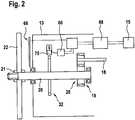
1 : eine erfindungsgemäße Handwerkzeugmaschine in schematischer Darstellung,2 : eine erste Ausführung einer erfindungsgemäßen Sicherheitsbremsvorrichtung in schematischer Darstellung.
1 FIG. 1: a hand-held power tool according to the invention in a schematic representation,2nd : A first embodiment of a safety brake device according to the invention in a schematic representation.
Beschreibungdescription
Für die in den unterschiedlichen Ausführungsbeispielen vorkommenden gleichen Bauteile werden dieselben Bezugszahlen verwendet.The same reference numerals are used for the same components occurring in the different exemplary embodiments.
Die Handkreissäge
Ein elektromotorischer Antrieb
Die Bearbeitungswelle
Erfindungsgemäß wird eine Annäherung und/oder Berührung eines menschlichen Körperteils, wie ein Finger, mit dem Bearbeitungswerkzeug
Die Erfassung einer Annäherung und/oder Berührung menschlicher Haut mit dem Bearbeitungswerkzeug
Ebenfalls ist es denkbar, sowohl für die Annäherung, als auch für die direkte Berührung unterschiedliche Arten von Sensorikeinheiten zu verwenden. Eine Erkennung der Annäherung kann ebenfalls über ein Radargestütztes System, eine Erkennung über NIR (Near Infra Red) oder über Magnetfelder (MRI: magnet resonanz imaging) erfolgen. Eine Erkennung durch Teraherzwellen, Röntgenstrahlen oder Induktion ist hier ebenfalls denkbar.It is also conceivable to use different types of sensor units both for approaching and for direct contact. Detection of the approach can also be carried out using a radar-based system, detection using NIR (Near Infra Red) or magnetic fields (MRI: magnetic resonance imaging). Detection by terahertz waves, X-rays or induction is also conceivable here.
Das Bremsritzel
Das PVE
Das PVE
The
Es ist aber auch denkbar, dass das PVE
Das PVE
Wird das Bearbeitungswerkzeug
Für die Bewegung des PVE
Claims (6)
Translated fromGermanPriority Applications (1)
| Application Number | Priority Date | Filing Date | Title |
|---|---|---|---|
| DE102018222413.7ADE102018222413A1 (en) | 2018-12-20 | 2018-12-20 | Hand tool with at least one safety brake device |
Applications Claiming Priority (1)
| Application Number | Priority Date | Filing Date | Title |
|---|---|---|---|
| DE102018222413.7ADE102018222413A1 (en) | 2018-12-20 | 2018-12-20 | Hand tool with at least one safety brake device |
Publications (1)
| Publication Number | Publication Date |
|---|---|
| DE102018222413A1true DE102018222413A1 (en) | 2020-06-25 |
Family
ID=70969843
Family Applications (1)
| Application Number | Title | Priority Date | Filing Date |
|---|---|---|---|
| DE102018222413.7APendingDE102018222413A1 (en) | 2018-12-20 | 2018-12-20 | Hand tool with at least one safety brake device |
Country Status (1)
| Country | Link |
|---|---|
| DE (1) | DE102018222413A1 (en) |
Citations (4)
| Publication number | Priority date | Publication date | Assignee | Title |
|---|---|---|---|---|
| US3785230A (en)* | 1972-11-08 | 1974-01-15 | Lokey Tool Inc | Automatic safety brake for rotary blade equipment |
| WO2003006213A2 (en)* | 2001-07-11 | 2003-01-23 | Black & Decker Inc. | Power tool safety mechanisms |
| US20080196565A1 (en)* | 2007-02-20 | 2008-08-21 | Eppard Erin F | Injury mitigation system for power tools |
| US20170190012A9 (en)* | 1999-10-01 | 2017-07-06 | Stephen F. Gass | Power equipment with detection and reaction systems |
- 2018
- 2018-12-20DEDE102018222413.7Apatent/DE102018222413A1/enactivePending
Patent Citations (4)
| Publication number | Priority date | Publication date | Assignee | Title |
|---|---|---|---|---|
| US3785230A (en)* | 1972-11-08 | 1974-01-15 | Lokey Tool Inc | Automatic safety brake for rotary blade equipment |
| US20170190012A9 (en)* | 1999-10-01 | 2017-07-06 | Stephen F. Gass | Power equipment with detection and reaction systems |
| WO2003006213A2 (en)* | 2001-07-11 | 2003-01-23 | Black & Decker Inc. | Power tool safety mechanisms |
| US20080196565A1 (en)* | 2007-02-20 | 2008-08-21 | Eppard Erin F | Injury mitigation system for power tools |
Similar Documents
| Publication | Publication Date | Title |
|---|---|---|
| DE102013202832A1 (en) | Hand tool and method for operating the hand tool | |
| CH702274A2 (en) | Hand machine tool device. | |
| DE102015226021A1 (en) | suction | |
| DE102004003202A1 (en) | Handle with detection device | |
| WO2017155476A1 (en) | Door handle assembly and process for extending and/or retracting of door handle assembly | |
| DE102007048052A1 (en) | Motor-driven hand machine tool i.e. motor chain saw, operating method, involves eliminating and/or reducing working movements of cutting tool to safe measure depending on detected machine movements of hand machine tool | |
| DE102018216573A1 (en) | Safety brake device | |
| DE102016220001A1 (en) | Hand tool | |
| DE112020000307T5 (en) | ELECTRICALLY DRIVEN WORK EQUIPMENT | |
| DE102015208252A1 (en) | Battery pack for a hand tool | |
| DE102017010814A1 (en) | Manual Pulse Generator Device | |
| DE102018222413A1 (en) | Hand tool with at least one safety brake device | |
| EP3873697B1 (en) | Safety braking device with two braking stages | |
| EP3845341B1 (en) | Handheld machine tool with finger protection | |
| DE102007011787A1 (en) | Handle for use with e.g. boring machine, has gripping unit and fastening unit arranged at distance from each other by damping unit, where contact surfaces of gripping and fastening units are profiled such that surfaces are enlarged | |
| DE102018222393A1 (en) | Hand tool with at least one safety brake device | |
| DE102019200693A1 (en) | Hand tool with at least one safety brake device | |
| DE102011115584A1 (en) | Door brake for motor car, has mechanically and/or electrically-operated device for variably or continuously adjusting opening angle and operated by handle of door of motor car, where device comprises electrical control device | |
| EP3263288B1 (en) | Handheld machine tool | |
| DE102018222440A1 (en) | Hand tool with at least one safety brake device | |
| DE102010032351A1 (en) | Hand-guided implement with operator recognition device | |
| DE102018222400A1 (en) | Hand tool with at least one safety brake device | |
| DE102019216276A1 (en) | Hand machine tool with at least one safety clutch | |
| EP2804262A1 (en) | Extendable electrical connection device for a work device | |
| DE102012112832A1 (en) | Machine tool device of e.g. sander, has electronic control unit that is configured to control and/or regulate tool drive unit in response to motion signal received using motion sensor |
Legal Events
| Date | Code | Title | Description |
|---|---|---|---|
| R163 | Identified publications notified |