DE102018221530A1 - LiDAR system and motor vehicle - Google Patents
LiDAR system and motor vehicleDownload PDFInfo
- Publication number
- DE102018221530A1 DE102018221530A1DE102018221530.8ADE102018221530ADE102018221530A1DE 102018221530 A1DE102018221530 A1DE 102018221530A1DE 102018221530 ADE102018221530 ADE 102018221530ADE 102018221530 A1DE102018221530 A1DE 102018221530A1
- Authority
- DE
- Germany
- Prior art keywords
- light wavelength
- lidar system
- wavelength range
- photodetector
- filter
- Prior art date
- Legal status (The legal status is an assumption and is not a legal conclusion. Google has not performed a legal analysis and makes no representation as to the accuracy of the status listed.)
- Withdrawn
Links
Images

Classifications
- G—PHYSICS
- G01—MEASURING; TESTING
- G01S—RADIO DIRECTION-FINDING; RADIO NAVIGATION; DETERMINING DISTANCE OR VELOCITY BY USE OF RADIO WAVES; LOCATING OR PRESENCE-DETECTING BY USE OF THE REFLECTION OR RERADIATION OF RADIO WAVES; ANALOGOUS ARRANGEMENTS USING OTHER WAVES
- G01S7/00—Details of systems according to groups G01S13/00, G01S15/00, G01S17/00
- G01S7/48—Details of systems according to groups G01S13/00, G01S15/00, G01S17/00 of systems according to group G01S17/00
- G01S7/481—Constructional features, e.g. arrangements of optical elements
- G01S7/4817—Constructional features, e.g. arrangements of optical elements relating to scanning
- G—PHYSICS
- G01—MEASURING; TESTING
- G01B—MEASURING LENGTH, THICKNESS OR SIMILAR LINEAR DIMENSIONS; MEASURING ANGLES; MEASURING AREAS; MEASURING IRREGULARITIES OF SURFACES OR CONTOURS
- G01B11/00—Measuring arrangements characterised by the use of optical techniques
- G01B11/22—Measuring arrangements characterised by the use of optical techniques for measuring depth
- B—PERFORMING OPERATIONS; TRANSPORTING
- B60—VEHICLES IN GENERAL
- B60W—CONJOINT CONTROL OF VEHICLE SUB-UNITS OF DIFFERENT TYPE OR DIFFERENT FUNCTION; CONTROL SYSTEMS SPECIALLY ADAPTED FOR HYBRID VEHICLES; ROAD VEHICLE DRIVE CONTROL SYSTEMS FOR PURPOSES NOT RELATED TO THE CONTROL OF A PARTICULAR SUB-UNIT
- B60W40/00—Estimation or calculation of non-directly measurable driving parameters for road vehicle drive control systems not related to the control of a particular sub unit, e.g. by using mathematical models
- B60W40/02—Estimation or calculation of non-directly measurable driving parameters for road vehicle drive control systems not related to the control of a particular sub unit, e.g. by using mathematical models related to ambient conditions
- G—PHYSICS
- G01—MEASURING; TESTING
- G01S—RADIO DIRECTION-FINDING; RADIO NAVIGATION; DETERMINING DISTANCE OR VELOCITY BY USE OF RADIO WAVES; LOCATING OR PRESENCE-DETECTING BY USE OF THE REFLECTION OR RERADIATION OF RADIO WAVES; ANALOGOUS ARRANGEMENTS USING OTHER WAVES
- G01S17/00—Systems using the reflection or reradiation of electromagnetic waves other than radio waves, e.g. lidar systems
- G01S17/88—Lidar systems specially adapted for specific applications
- G01S17/89—Lidar systems specially adapted for specific applications for mapping or imaging
- G—PHYSICS
- G01—MEASURING; TESTING
- G01S—RADIO DIRECTION-FINDING; RADIO NAVIGATION; DETERMINING DISTANCE OR VELOCITY BY USE OF RADIO WAVES; LOCATING OR PRESENCE-DETECTING BY USE OF THE REFLECTION OR RERADIATION OF RADIO WAVES; ANALOGOUS ARRANGEMENTS USING OTHER WAVES
- G01S17/00—Systems using the reflection or reradiation of electromagnetic waves other than radio waves, e.g. lidar systems
- G01S17/88—Lidar systems specially adapted for specific applications
- G01S17/93—Lidar systems specially adapted for specific applications for anti-collision purposes
- G01S17/931—Lidar systems specially adapted for specific applications for anti-collision purposes of land vehicles
- G—PHYSICS
- G01—MEASURING; TESTING
- G01S—RADIO DIRECTION-FINDING; RADIO NAVIGATION; DETERMINING DISTANCE OR VELOCITY BY USE OF RADIO WAVES; LOCATING OR PRESENCE-DETECTING BY USE OF THE REFLECTION OR RERADIATION OF RADIO WAVES; ANALOGOUS ARRANGEMENTS USING OTHER WAVES
- G01S7/00—Details of systems according to groups G01S13/00, G01S15/00, G01S17/00
- G01S7/48—Details of systems according to groups G01S13/00, G01S15/00, G01S17/00 of systems according to group G01S17/00
- G01S7/481—Constructional features, e.g. arrangements of optical elements
- G01S7/4814—Constructional features, e.g. arrangements of optical elements of transmitters alone
- G01S7/4815—Constructional features, e.g. arrangements of optical elements of transmitters alone using multiple transmitters
- G—PHYSICS
- G01—MEASURING; TESTING
- G01S—RADIO DIRECTION-FINDING; RADIO NAVIGATION; DETERMINING DISTANCE OR VELOCITY BY USE OF RADIO WAVES; LOCATING OR PRESENCE-DETECTING BY USE OF THE REFLECTION OR RERADIATION OF RADIO WAVES; ANALOGOUS ARRANGEMENTS USING OTHER WAVES
- G01S7/00—Details of systems according to groups G01S13/00, G01S15/00, G01S17/00
- G01S7/48—Details of systems according to groups G01S13/00, G01S15/00, G01S17/00 of systems according to group G01S17/00
- G01S7/481—Constructional features, e.g. arrangements of optical elements
- G01S7/4816—Constructional features, e.g. arrangements of optical elements of receivers alone
- B—PERFORMING OPERATIONS; TRANSPORTING
- B60—VEHICLES IN GENERAL
- B60W—CONJOINT CONTROL OF VEHICLE SUB-UNITS OF DIFFERENT TYPE OR DIFFERENT FUNCTION; CONTROL SYSTEMS SPECIALLY ADAPTED FOR HYBRID VEHICLES; ROAD VEHICLE DRIVE CONTROL SYSTEMS FOR PURPOSES NOT RELATED TO THE CONTROL OF A PARTICULAR SUB-UNIT
- B60W2420/00—Indexing codes relating to the type of sensors based on the principle of their operation
- B60W2420/40—Photo, light or radio wave sensitive means, e.g. infrared sensors
- B60W2420/408—Radar; Laser, e.g. lidar
Landscapes
- Engineering & Computer Science (AREA)
- Physics & Mathematics (AREA)
- General Physics & Mathematics (AREA)
- Computer Networks & Wireless Communication (AREA)
- Radar, Positioning & Navigation (AREA)
- Remote Sensing (AREA)
- Electromagnetism (AREA)
- Automation & Control Theory (AREA)
- Transportation (AREA)
- Mechanical Engineering (AREA)
- Mathematical Physics (AREA)
- Optical Radar Systems And Details Thereof (AREA)
- Transforming Light Signals Into Electric Signals (AREA)
Abstract
Translated fromGerman
Description
Translated fromGermanDie vorliegende Erfindung betrifft ein LiDAR-System, das dafür eingerichtet ist, eine Umwelt mit einem Lichtstrahl abzutasten, um Tiefeninformationen über die Umwelt zu erfassen.The present invention relates to a LiDAR system which is set up to scan an environment with a light beam in order to acquire depth information about the environment.
Die vorliegende Erfindung betrifft weiter ein Kraftfahrzeug mit einem solchen LiDAR-System, wobei das LiDAR-System mit dem Kraftfahrzeug wirkverbunden ist.The present invention further relates to a motor vehicle with such a LiDAR system, the LiDAR system being operatively connected to the motor vehicle.
Stand der TechnikState of the art
Solche LiDAR-Systeme und Kraftfahrzeuge sind grundsätzlich bekannt. Sie weisen beispielsweise eine Lawinenphotodiode als einen Photodetektor auf, beispielsweise eine Einzelphotonen-Lawinenphotodiode (engl. single-photon avalanche diode, SPAD), oder stattdessen einen Silizium-Photomultiplier (SiPM) als Photodetektor. Das LiDAR-System kann eine Laserquelle aufweisen, um den Lichtstrahl auszusenden. Der Photodetektor ist dafür angeordnet, den von der Umwelt reflektierten Lichtstrahl zu empfangen. Aus Empfangssignalen des Photodetektors kann dann eine Auswerteelektronik die Tiefeninformationen erhalten.Such LiDAR systems and motor vehicles are generally known. For example, they have an avalanche photodiode as a photodetector, for example a single-photon avalanche diode (SPAD), or instead a silicon photomultiplier (SiPM) as a photodetector. The LiDAR system can have a laser source in order to emit the light beam. The photodetector is arranged to receive the light beam reflected from the environment. Evaluation electronics can then receive the depth information from received signals from the photodetector.
Aus der
In der
Weiter sind grundsätzlich SPAD-Sensoriken mit Rot-, Grün- und Blau- (RGB-) Farbkanälen und mit separaten Photodetektoren bekannt.Furthermore, SPAD sensors with red, green and blue (RGB) color channels and with separate photodetectors are known.
Die Veröffentlichungsnummer
Die Veröffentlichungsnummer
Die Veröffentlichungsnummer
Offenbarung der ErfindungDisclosure of the invention
Erfindungsgemäß wird ein LiDAR-System der eingangs genannten Art zur Verfügung gestellt, wobei das LiDAR-System zusätzlich dafür eingerichtet ist, Farbinformationen über die Umwelt zu erfassen.According to the invention, a LiDAR system of the type mentioned at the outset is made available, the LiDAR system being additionally set up to record color information about the environment.
Vorteile der ErfindungAdvantages of the invention
Das erfindungsgemäße LiDAR-System hat den Vorteil, dass das LiDAR-System um die Erfassung von Farbinformationen über die Umwelt erweitert ist. Das LiDAR-System stellt somit gleichzeitig sowohl eine herkömmliche LiDAR-Abtastfunktion, zur Erfassung von Tiefeninformationen, als auch eine passive Farbbildkamera, zur Erfassung von Farbinformationen, bereit. Die mehrheitlichen Farbeigenschaften von Objekten können ermittelt sowie vorzugsweise zeitsynchron mit ihrer Entfernung in Relation gesetzt werden. Eine passive Farbbildkamera kann in einem einzigen Gerät mit einem LiDAR-Betrieb kombiniert sein.The LiDAR system according to the invention has the advantage that the LiDAR system is expanded to include color information about the environment. The LiDAR system thus simultaneously provides both a conventional LiDAR scanning function for capturing depth information and a passive color image camera for capturing color information. The majority of the color properties of objects can be determined and, preferably, synchronized with their distance in relation to time. A passive color camera can be combined with LiDAR operation in a single device.
Bevorzugt ist, dass das LiDAR-System dafür eingerichtet ist, aus Empfangssignalen von einem oder mehreren Photodetektoren ein Farbsignal zu bilden, um die Farbinformationen über die Umwelt zu erfassen. Vorzugsweise sind der eine oder die mehreren Photodetektoren zusätzlich dafür eingerichtet, die Tiefeninformationen zu erfassen. Photodetektoren sind in LiDAR-Systemen oft ohnehin zur Erfassung der Tiefeninformationen vorhanden und können so eine zusätzliche Funktion übernehmen. Der doppelte Nutzen der Photodetektoren erlaubt beispielsweise eine optimale zeitliche Synchronisation von Farb- und Tiefeninformationen. Entsprechend ist das LiDAR-System vorzugsweise dafür eingerichtet, die Farb- und Tiefeninformationen synchronisiert zu erfassen und vorzugsweise auch synchronisiert auszugeben, vorzugsweise durch die Auswerteelektronik. Auch wird so vorzugsweise die Kombination von Tiefen- und Farbenerfassung in einem einzigen optischen Pfad ermöglicht, was Vorteile zum Beispiel bei der Baugröße mit sich bringen kann. Das LiDAR-System ist besonders vorzugsweise dafür eingerichtet, aus Empfangssignalen von mehreren Photodetektoren ein zusammengesetztes Farbsignal zu bilden, um die Farbinformationen über die Umwelt zu erfassen. Hierzu kann eine entsprechend eingerichtete Auswerteelektronik im LiDAR-System vorgesehen sein. Das zusammengesetzte Farbsignal ist vorzugsweise das RGB-Signal, besonders vorzugsweise ein RGBIR-Signal, das neben Rot, Grün und Blau auch noch Infrarotdaten (IR) einschließt. Da somit bereits das LiDAR-System dafür eingerichtet ist, das zusammengesetzte Farbsignal zu bilden, kann auf eine anschließende Zusammensetzung von Empfangssignalen zur Bildung des zusammengesetzten Farbsignals im Rahmen einer zeitlich nachgelagerten Auswertung verzichtet werden. Für die Detektion von Objekteigenschaften in der Umwelt werden von dem LiDAR-System durch die RGB-Signale drei zusätzliche Parameter erfasst. Damit können beispielsweise Machine-Learning-Algorithmen verbessert werden. Bevorzugte Photodetektoren sind Halbleiterdetektoren, insbesondere hergestellt aus Silizium, Galliumarsenid oder Indiumphosphid. Die Verwendung der Photodetektoren, um das Farbsignal zu bilden, kann außerdem den Vorteil haben, dass Belichtungszeiten von der Größenordnung Millisekunden, die gängige übliche Farbkameras für Farbpixel erfordern, auf die Größenordnung Nanosekunden verringert werden können. It is preferred that the LiDAR system is set up to form a color signal from received signals from one or more photodetectors in order to capture the color information about the environment. The one or more photodetectors are preferably additionally set up to acquire the depth information. In LiDAR systems, photodetectors are often already available to record the depth information and can therefore perform an additional function. The dual use of the photodetectors allows, for example, optimal time synchronization of color and depth information. Accordingly, the LiDAR system is preferably set up to acquire the color and depth information in a synchronized manner and preferably also to output it in a synchronized manner, preferably by means of the evaluation electronics. This also preferably enables the combination of depth and color detection in a single optical path, which can have advantages, for example in terms of size. The LiDAR system is particularly preferably set up to form a composite color signal from received signals from a plurality of photodetectors in order to capture the color information about the environment. For this purpose, correspondingly configured evaluation electronics can be provided in the LiDAR system. The composite color signal is preferably the RGB signal, particularly preferably an RGBIR signal, which in addition to red, green and blue also includes infrared data (IR). Since the LiDAR system is thus already set up to form the composite color signal, a subsequent combination of received signals to form the composite color signal as part of a subsequent evaluation can be dispensed with. For the detection of object properties in the environment, the LiDAR system records three additional parameters using the RGB signals. This can be used, for example, to improve machine learning algorithms. Preferred photodetectors are semiconductor detectors, in particular made of silicon, gallium arsenide or indium phosphide. The use of the photodetectors to form the color signal can also have the advantage that exposure times of the order of milliseconds that common color cameras for color pixels require can be reduced to the order of nanoseconds.
Bevorzugt ist, dass das LiDAR-System eine erste Photodetektoranordnung und eine zweite Photodetektoranordnung aufweist. Die erste Photodetektoranordnung ist vorzugsweise dafür eingerichtet ist, einen ersten Lichtwellenlängenbereich zu empfangen. Der erste Lichtwellenlängenbereich ist vorzugsweise der Lichtwellenlängenbereich von Rotlicht. Daher liegt der erste Lichtwellenlängenbereich insbesondere zwischen 585 nm und 780 nm. Der erste Lichtwellenlängenbereich kann allerdings nach oben oder unten leicht abweichen oder auch auf einen vorbestimmten Wert innerhalb des genannten Intervalls festgelegt sein, wie beispielsweise auf genau 650 nm. So kann die Selektivität der ersten Photodetektoranordnung je nach Anwendung erhöht oder verringert werden. Die zweite Photodetektoranordnung ist vorzugsweise dafür eingerichtet, einen zweiten Lichtwellenlängenbereich zu empfangen. Der zweite Lichtwellenlängenbereich ist vorzugsweise der Lichtwellenlängenbereich von Grünlicht. Daher liegt der erste Lichtwellenlängenbereich insbesondere zwischen 497 nm und 585 nm. Der zweite Lichtwellenlängenbereich kann allerdings nach oben oder unten leicht abweichen oder auch auf einen vorbestimmten Wert innerhalb des genannten Intervalls festgelegt sein, wie beispielsweise auf genau 510 nm. So kann die Selektivität der zweiten Photodetektoranordnung je nach Anwendung erhöht oder verringert werden. Der erste Lichtwellenlängenbereich ist vorzugsweise von dem zweiten Lichtwellenlängenbereich mindestens teilweise verschieden. In manchen Ausführungsformen ist vorgesehen, dass sich der erste Lichtwellenlängenbereich und der zweite Lichtwellenlängenbereich überlappen. In anderen Ausführungsformen ist vorgesehen, dass der erste Lichtwellenlängenbereich und der zweite Lichtwellenlängenbereich separiert sind. So erlaubt das LiDAR-System, zwei Lichtwellenlängenbereiche als unterschiedliche Farbinformationen über die Umwelt zu erfassen. Mit anderen Worten stellt das LiDAR-System in dieser Ausführungsform somit gleichzeitig sowohl eine herkömmliche LiDAR-Abtastfunktion, zur Erfassung von Tiefeninformationen, als auch eine zweifarbige passive Farbbildkamera, zur Erfassung von Farbinformationen, bereit, nämlich für den ersten Lichtwellenlängenbereich und für den zweiten Lichtwellenlängenbereich. Dies kann zu sinkenden Kosten, sinkender Baugröße und einem Entfallen von Justage- und Kalibrierungsaufwand führen.It is preferred that the LiDAR system has a first photodetector arrangement and a second photodetector arrangement. The first photodetector arrangement is preferably set up to receive a first light wavelength range. The first light wavelength range is preferably the light wavelength range of red light. The first light wavelength range is therefore in particular between 585 nm and 780 nm. However, the first light wavelength range can deviate slightly upwards or downwards or can also be set to a predetermined value within the specified interval, for example exactly 650 nm Depending on the application, the photodetector arrangement can be increased or decreased. The second photodetector arrangement is preferably set up to receive a second light wavelength range. The second light wavelength range is preferably the light wavelength range of green light. Therefore, the first light wavelength range is in particular between 497 nm and 585 nm. However, the second light wavelength range can deviate slightly upwards or downwards or can also be set to a predetermined value within the interval mentioned, such as, for example, exactly 510 nm Depending on the application, the photodetector arrangement can be increased or decreased. The first light wavelength range is preferably at least partially different from the second light wavelength range. In some embodiments, it is provided that the first light wavelength range and the second light wavelength range overlap. In other embodiments it is provided that the first light wavelength range and the second light wavelength range are separated. The LiDAR system allows two light wavelength ranges to be recorded as different color information about the environment. In other words, the LiDAR system in this embodiment thus simultaneously provides both a conventional LiDAR scanning function for capturing depth information and a two-color passive color image camera for capturing color information, namely for the first light wavelength range and for the second light wavelength range. This can lead to falling costs, a smaller size and no adjustment and calibration effort.
In einigen Ausführungsformen weist das LiDAR-System eine dritte Photodetektoranordnung auf. Bevorzugt ist, dass die dritte Photodetektoranordnung dafür eingerichtet ist, einen dritten Lichtwellenlängenbereich zu empfangen. Der dritte Lichtwellenlängenbereich ist vorzugsweise der Lichtwellenlängenbereich von Blaulicht. Daher liegt der dritte Lichtwellenlängenbereich insbesondere zwischen 380 nm und 497 nm. Der dritte Lichtwellenlängenbereich kann allerdings nach oben oder unten leicht abweichen oder auch auf einen vorbestimmten Wert innerhalb des genannten Intervalls festgelegt sein, wie beispielsweise auf genau 490 nm. So kann die Selektivität der dritten Photodetektoranordnung je nach Anwendung erhöht oder verringert werden. In manchen Ausführungsformen ist der dritte Lichtwellenlängenbereich von dem ersten Lichtwellenlängenbereich mindestens teilweise verschieden. In einigen Ausführungsformen ist der dritte Lichtwellenlängenbereich von dem zweiten Lichtwellenlängenbereich mindestens teilweise verschieden. Manche Ausführungsformen sehen jedoch vor, dass der dritte Lichtwellenlängenbereich und der zweite Lichtwellenlängenbereich überlappen. Sind drei Lichtwellenlängenbereiche zur Erfassung vorgesehen, kann auf einfache Weise ein dreifarbiges Farbsignal, insbesondere das RGB-Signal, durch das LiDAR-System bereitgestellt werden. Das dreifarbige Farbsignal kann in Ausführungsformen über drei separate Farbkanäle durch das LiDAR-System bereitgestellt werden, von denen jeder eines der drei Farbsignale bereitstellt.In some embodiments, the LiDAR system has a third photodetector array. It is preferred that the third photodetector arrangement is set up to receive a third light wavelength range. The third light wavelength range is preferably the light wavelength range of blue light. The third light wavelength range is therefore in particular between 380 nm and 497 nm. However, the third light wavelength range can deviate slightly upwards or downwards or can also be set to a predetermined value within the specified interval, such as, for example, exactly 490 nm Depending on the application, the photodetector arrangement can be increased or decreased. In some embodiments, the third light wavelength range is at least partially different from the first light wavelength range. In some embodiments, the third is Light wavelength range at least partially different from the second light wavelength range. However, some embodiments provide that the third light wavelength range and the second light wavelength range overlap. If three light wavelength ranges are provided for detection, a three-color color signal, in particular the RGB signal, can be provided by the LiDAR system in a simple manner. In embodiments, the tri-color signal can be provided by the LiDAR system over three separate color channels, each of which provides one of the three color signals.
Das LiDAR-System weist in einigen Ausführungsformen eine vierte Photodetektoranordnung auf. Die vierte Photodetektoranordnung ist vorzugsweise dafür eingerichtet, einen vierten Lichtwellenlängenbereich zu empfangen. Der vierte Lichtwellenlängenbereich ist vorzugsweise der Lichtwellenlängenbereich von IR-Licht. Daher liegt der vierte Lichtwellenlängenbereich insbesondere zwischen 700 nm und 1 mm. Der vierte Lichtwellenlängenbereich kann allerdings nach oben oder unten abweichen oder auch auf einen vorbestimmten Wert innerhalb des genannten Intervalls festgelegt sein, wie beispielsweise auf genau 780 nm. So kann die Selektivität der vierten Photodetektoranordnung je nach Anwendung erhöht oder verringert werden. In manchen Ausführungsformen liegt der vierte Lichtwellenlängenbereich im Bereich von nahem Infrarot (NIR) und/oder mittlerem Infrarot (MIR) und/oder fernem Infrarot (FIR). Bevorzugt ist, dass der vierte Lichtwellenlängenbereich von dem ersten Lichtwellenlängenbereich mindestens teilweise verschieden ist. Weiter ist bevorzugt, dass der vierte Lichtwellenlängenbereich von dem zweiten Lichtwellenlängenbereich mindestens teilweise verschieden ist. Ebenfalls ist bevorzugt, dass der vierte Lichtwellenlängenbereich von dem dritten Lichtwellenlängenbereich mindestens teilweise verschieden ist. In manchen Ausführungsformen überlappen der erste Lichtwellenlängenbereich und der vierte Lichtwellenlängenbereich. In einigen Ausführungsformen sind jedoch der erste Lichtwellenlängenbereich und der vierte Lichtwellenlängenbereich voneinander separiert. Sieht das LiDAR-System die vier Photodetektoranordnungen vor, so kann auf einfache Weise ein vierfarbiges Farbsignal, insbesondere das RGBIR-Signal, durch das LiDAR-System bereitgestellt werden. Die vier Farbsignale können über vier separate Farbkanäle durch das LiDAR-System bereitgestellt werden, von denen jeder eines der vier Farbsignale bereitstellt.The LiDAR system has a fourth photodetector array in some embodiments. The fourth photodetector arrangement is preferably set up to receive a fourth light wavelength range. The fourth light wavelength range is preferably the light wavelength range of IR light. The fourth light wavelength range is therefore in particular between 700 nm and 1 mm. However, the fourth light wavelength range can deviate upwards or downwards or can also be fixed to a predetermined value within the specified interval, such as, for example, exactly 780 nm. The selectivity of the fourth photodetector arrangement can be increased or decreased depending on the application. In some embodiments, the fourth light wavelength range is in the near infrared (NIR) and / or medium infrared (MIR) and / or far infrared (FIR) range. It is preferred that the fourth light wavelength range is at least partially different from the first light wavelength range. It is further preferred that the fourth light wavelength range is at least partially different from the second light wavelength range. It is also preferred that the fourth light wavelength range is at least partially different from the third light wavelength range. In some embodiments, the first light wavelength range and the fourth light wavelength range overlap. In some embodiments, however, the first light wavelength range and the fourth light wavelength range are separated from one another. If the LiDAR system provides the four photodetector arrangements, then a four-color color signal, in particular the RGBIR signal, can be provided by the LiDAR system in a simple manner. The four color signals can be provided by the LiDAR system via four separate color channels, each of which provides one of the four color signals.
Vorzugsweise stellt die erste Photodetektoranordnung das Rotsignal bereit. Vorzugsweise stellt die zweite Photodetektoranordnung das Grünsignal bereit. Vorzugsweise stellt die dritte Photodetektoranordnung das Blausignal bereit. Vorzugsweise stellt die vierte Photodetektoranordnung das IR-Signal bereit. Allerdings kann die erste Photodetektoranordnung in manchen Ausführungsformen sowohl das Rotsignal als auch das IR-Signal in Kombination bereitstellen. Der erste Lichtwellenlängenbereich liegt dann insbesondere zwischen 585 nm bis zu 1 mm. So können Rotsignal, Grünsignal, Blausignal und IR-Signal mit nur drei Photodetektoranordnungen bereitgestellt werden, vorzugsweise über nur drei Farbkanäle.The first photodetector arrangement preferably provides the red signal. The second photodetector arrangement preferably provides the green signal. The third photodetector arrangement preferably provides the blue signal. The fourth photodetector arrangement preferably provides the IR signal. However, in some embodiments, the first photodetector arrangement can provide both the red signal and the IR signal in combination. The first light wavelength range then lies in particular between 585 nm and 1 mm. For example, the red signal, green signal, blue signal and IR signal can be provided with only three photodetector arrangements, preferably over only three color channels.
In manchen Ausführungsformen sind zwei oder mehr der Photodetektoranordnungen in einer gemeinsamen Detektormatrix angeordnet. Bevorzugt ist, dass zwei oder mehr der Photodetektoranordnungen ein gemeinsames Detektorbauteil bilden. Dies hat den Vorteil, dass der Justierungs- und Konfigurationsaufwand sinken kann, weil vor Inbetriebnahme nicht länger einzelne Photodetektoranordnungen in Abhängigkeit voneinander konfiguriert werden müssen, sondern zwei der mehr Photodetektoranordnungen als vorkonfiguriertes gemeinsames Bauteil bereitgestellt werden können. Besonders bevorzugt ist, dass alle Photodetektoranordnungen in der gemeinsamen Detektormatrix angeordnet sind und ein gemeinsames Detektorbauteil bilden. Vorzugsweise weist die Detektormatrix Zeilen und Spalten auf, wobei vorzugsweise die Anzahl der Zeilen gleich der Anzahl der Spalten ist. Vorzugsweise sind drei oder mehr Zeilen und/oder drei oder mehr Spalten vorhanden, besonders vorzugsweise vier oder mehr Zeilen und/oder vier oder mehr Spalten, ganz besonders vorzugsweise mehr als fünf oder mehr Zeilen und/oder fünf oder mehr Spalten.In some embodiments, two or more of the photodetector arrays are arranged in a common detector matrix. It is preferred that two or more of the photodetector arrangements form a common detector component. This has the advantage that the adjustment and configuration effort can be reduced because individual photodetector arrangements no longer have to be configured as a function of one another before start-up, but two of the more photodetector arrangements can be provided as a preconfigured common component. It is particularly preferred that all photodetector arrangements are arranged in the common detector matrix and form a common detector component. The detector matrix preferably has rows and columns, the number of rows preferably being equal to the number of columns. There are preferably three or more rows and / or three or more columns, particularly preferably four or more rows and / or four or more columns, very particularly preferably more than five or more rows and / or five or more columns.
Bevorzugt ist, dass jeder der Photodetektoren genau einer der Photodetektoranordnungen zugeordnet ist. Bevorzugt ist zudem, dass in der Detektormatrix zueinander in einer Zeile und/oder Spalte benachbarte Photodetektoren zu unterschiedlichen Photodetektoranordnungen zugeordnet sind. Vorzugsweise sind in jeder Zeile der Detektormatrix mehrere, besonders vorzugsweise genau zwei, der Photodetektoranordnungen miteinander abwechselnd verschränkt. Jedem der Photodetektoren ist vorzugsweise ein Lichtwellenlängenfilter vorgelagert, das für den Lichtwellenlängenbereich durchlässig ist, der durch die jeweilige Photodetektoranordnung empfangen werden soll. Das Lichtwellenlängenfilter, das den Photodetektoren der ersten Photodetektoranordnung jeweils vorgelagert ist, ist vorzugsweise für den ersten Lichtwellenlängenbereich durchlässig. Das Lichtwellenlängenfilter, das den Photodetektoren der zweiten Photodetektoranordnung jeweils vorgelagert ist, ist vorzugsweise für den zweiten Lichtwellenlängenbereich durchlässig. Das Lichtwellenlängenfilter, das den Photodetektoren der dritten Photodetektoranordnung jeweils vorgelagert ist, ist vorzugsweise für den dritten Lichtwellenlängenbereich durchlässig. Das Lichtwellenlängenfilter, das den Photodetektoren der vierten Photodetektoranordnung jeweils vorgelagert ist, ist vorzugsweise für den vierten Lichtwellenlängenbereich durchlässig. Anders ausgedrückt, wird die Zuordnung der Photodetektoren zu den jeweiligen Photodetektoranordnungen durch das jeweils vorgelagerte Lichtwellenlängenfilter bestimmt. Die Anzahl unterschiedlicher Lichtwellenlängenfilter bestimmt die Anzahl der Photodetektoranordnungen. Ist also beispielsweise eine Vielzahl von Lichtwellenlängenfiltern vorgesehen, die insgesamt für drei unterschiedliche Lichtwellenlängen durchlässig sind, so sind dadurch drei Photodetektoranordnungen definiert. Der Vorteil davon kann sein, dass die Photodetektoren selbst alle identisch, insbesondere hinsichtlich der von ihnen empfangbaren Lichtwellenlänge, ausgeführt sein können und nur das jeweils vorgelagerte Lichtwellenlängenfilter bestimmt, welcher Lichtwellenlängenbereich durch den dahinterliegenden Photodetektor erfasst wird. Alternativ können aber die Photodetektoren selbst wellenlängenselektiv eingerichtet sein, sodass auf die in Detektionsrichtung vorgelagerten Lichtwellenlängenfilter verzichtet werden kann. Dann bilden alle die Photodetektoren, die dieselbe Wellenlängenselektivität aufweisen, eine jeweilige Photodetektoranordnung, die durch ihre jeweilige Wellenlängenselektivität definiert ist.It is preferred that each of the photodetectors is assigned to exactly one of the photodetector arrangements. It is also preferred that in the detector matrix adjacent photodetectors to one another in a row and / or column are assigned to different photodetector arrangements. Preferably, in each row of the detector matrix, several, particularly preferably exactly two, of the photodetector arrangements are alternately interlaced. Each of the photodetectors is preferably preceded by a light wavelength filter that is transparent to the light wavelength range that is to be received by the respective photodetector arrangement. The light wavelength filter, which is in front of the photodetectors of the first photodetector arrangement, is preferably transparent to the first light wavelength range. The light wavelength filter, which is located upstream of the photodetectors of the second photodetector arrangement, is preferably transparent to the second light wavelength range. The light wavelength filter, which is in front of the photodetectors of the third photodetector arrangement, is preferably transparent to the third light wavelength range. The light wavelength filter, which is in front of the photodetectors of the fourth photodetector arrangement, is preferred transparent for the fourth light wavelength range. In other words, the assignment of the photodetectors to the respective photodetector arrangements is determined by the upstream light wavelength filter. The number of different light wavelength filters determines the number of photodetector arrangements. If, for example, a multiplicity of light wavelength filters are provided which are transparent to a total of three different light wavelengths, three photodetector arrangements are thereby defined. The advantage of this can be that the photodetectors themselves can all be embodied identically, in particular with regard to the light wavelength that they can receive, and only the upstream light wavelength filter determines which light wavelength range is detected by the photodetector behind it. Alternatively, however, the photodetectors themselves can be set up to be wavelength-selective, so that the upstream light wavelength filters can be dispensed with. Then all of the photodetectors that have the same wavelength selectivity form a respective photodetector arrangement that is defined by their respective wavelength selectivity.
Bevorzugt ist, dass mehrere der Lichtwellenlängenfilter in einer gemeinsamen Filtermatrix angeordnet sind und ein gemeinsames Filterbauteil bilden. Die Filtermatrix ist vorzugsweise, mit anderen Worten, im optischen Empfangspfad einem SPAD-basierten Detektor in SiPM-Konfiguration (SPAD-Array) vorgesetzt. Besonders vorzugsweise entspricht eine Gestaltung der Filtermatrix einer Gestaltung der Detektormatrix, sodass jeweils einer der Lichtwellenlängenfilter einem der Photodetektoren vorgelagert ist. Dies hat den Vorteil, dass der Justierungs- und Konfigurationsaufwand sinken kann, weil vor Inbetriebnahme nicht länger einzelne Lichtwellenlängenfilter in Abhängigkeit voneinander konfiguriert werden müssen, sondern zwei der mehr Lichtwellenlängenfilter als vorkonfiguriertes gemeinsames Bauteil bereitgestellt werden können. Besonders bevorzugt ist, dass alle Lichtwellenlängenfilter in der gemeinsamen Filtermatrix angeordnet sind und ein gemeinsames Filterbauteil bilden. Vorzugsweise weist die Filtermatrix Zeilen und Spalten auf, wobei vorzugsweise die Anzahl der Zeilen gleich der Anzahl der Spalten ist. Vorzugsweise sind drei oder mehr Zeilen und/oder drei oder mehr Spalten vorhanden, besonders vorzugsweise vier oder mehr Zeilen und/oder vier oder mehr Spalten, ganz besonders vorzugsweise mehr als fünf oder mehr Zeilen und/oder fünf oder mehr Spalten. Vorzugsweise entspricht die Anzahl der Zeilen und Spalten der Filtermatrix der Anzahl der Zeilen und Spalten der Detektormatrix. So kann besonders einfach eine exakte Bedeckung der Photodioden mit den jeweiligen Lichtwellenlängenfiltern erfolgen, um die verschiedenen Photodetektoranordnungen zu definieren. Entsprechend ist eine bevorzugte Filtermatrix ein RGBIR-Farbfeldarray oder ein modifizierter Bayerfilter. Die Lichtwellenlängenfilter können vorzugsweise aus organischen Farbstoffen oder beschichteten Bragg-Filter-Strukturen hergestellt sein. Somit erlaubt die Erfindung also die Verwendung kostengünstiger, schmalbandiger optischer Wellenlängenfilter-Arrays.It is preferred that several of the light wavelength filters are arranged in a common filter matrix and form a common filter component. In other words, the filter matrix is preferably placed in front of a SPAD-based detector in SiPM configuration (SPAD array) in the optical reception path. A design of the filter matrix particularly preferably corresponds to a design of the detector matrix, so that in each case one of the light wavelength filters is arranged upstream of one of the photodetectors. This has the advantage that the adjustment and configuration effort can be reduced, because prior to commissioning, individual light wavelength filters no longer have to be configured as a function of one another, but two of the more light wavelength filters can be provided as a preconfigured common component. It is particularly preferred that all light wavelength filters are arranged in the common filter matrix and form a common filter component. The filter matrix preferably has rows and columns, the number of rows preferably being equal to the number of columns. There are preferably three or more rows and / or three or more columns, particularly preferably four or more rows and / or four or more columns, very particularly preferably more than five or more rows and / or five or more columns. The number of rows and columns of the filter matrix preferably corresponds to the number of rows and columns of the detector matrix. In this way, the photodiodes can be covered with the respective light wavelength filters in a particularly simple manner in order to define the various photodetector arrangements. Accordingly, a preferred filter matrix is an RGBIR color field array or a modified Bayer filter. The light wavelength filters can preferably be made from organic dyes or coated Bragg filter structures. The invention thus allows the use of inexpensive, narrow-band optical wavelength filter arrays.
Mindestens einer der Photodetektoren ist vorzugsweise eine Einzelphotonen-Lawinenphotodiode. Derartige Einzelphotonen-Lawinenphotodioden sind dafür eingerichtet, einzelne Photonen unabhängig von ihrer Lichtwellenlänge zu zählen. Das vereinfacht die Konstruktion des LiDAR-Systems, denn aufgrund der den Photodetektoren vorzugsweise vorgelagerten Lichtwellenlängenfilter müssen die Photodetektoren nicht selbst die Lichtwellenlänge filtern, sondern müssen nur noch die bereits gefilterten Photonen zählen. Dies erlaubt die Verwendung von einer Vielzahl identischer Photodetektoren und somit eine kostengünstige Lösung. Deshalb ist besonders bevorzugt, dass alle der Photodetektoren Einzelphotonen-Lawinenphotodioden sind. Mit anderen Worten ausgedrückt, können die einzelnen SPAD nur Photonen zählen. Da aber die einzelnen Lichtwellenlängenfilter der Filtermatrix nur Photonen der richtigen Frequenz beziehungsweise Wellenlänge transmittieren, zählen einzelne, dahinterliegende SPAD genau diese Photonen, die anschließend den Farben beziehungsweise dem IR-Kanal zugeordnet werden können. Bevorzugt ist, dass aus dem Empfangssignal der Einzelphotonen-Lawinenphotodiode sowohl die Tiefeninformationen als auch die Farbinformationen erhalten werden. So kann die Einzelphotonen-Lawinenphotodiode eine doppelte Funktion übernehmen, bei vorzugsweise deutlicher Reduktion von Belichtungszeiten gegenüber gängigen Farbkameras.At least one of the photodetectors is preferably a single-photon avalanche photodiode. Such single-photon avalanche photodiodes are set up to count individual photons regardless of their light wavelength. This simplifies the construction of the LiDAR system, because due to the light wavelength filters that are preferably placed in front of the photodetectors, the photodetectors do not have to filter the light wavelength themselves, but only have to count the photons that have already been filtered. This allows the use of a large number of identical photodetectors and thus an inexpensive solution. It is therefore particularly preferred that all of the photodetectors are single-photon avalanche photodiodes. In other words, the individual SPADs can only count photons. However, since the individual light wavelength filters of the filter matrix only transmit photons of the correct frequency or wavelength, individual SPADs lying behind count exactly these photons, which can then be assigned to the colors or the IR channel. It is preferred that both the depth information and the color information are obtained from the received signal of the single-photon avalanche photodiode. The single-photon avalanche photodiode can thus take on a double function, with preferably a significant reduction in exposure times compared to conventional color cameras.
Bevorzugt ist, dass das Detektorbauteil und das Filterbauteil ein gemeinsames Bauelement bilden. Das Filterbauteil und das Detektorbauteil können beispielsweise hoch integriert in einem zusammenhängenden Reinraumprozess gefertigt und zu dem gemeinsamen Bauelement zusammengesetzt werden. Damit kann ein späterer Justageaufwand entfallen. Vorzugsweise sind das Detektorbauteil und das Filterbauteil miteinander stoffschlüssig verbunden, insbesondere verklebt, um das gemeinsame Bauelement zu bilden. Dies kann eine einfache, kostengünstige und effiziente Möglichkeit sein, das gemeinsame Bauelement zu fertigen. In Ausführungsformen sind die Photodetektoren jeweils einzeln in einem Innenraum, der zwischen Filterbauteil und Detektorbauteil gebildet ist, verkapselt. So kann jeder Photodetektor auf dem Detektorbauteil separat gut geschützt sein. In manchen Ausführungsformen ist jedoch vorgesehen, dass mehrere Photodetektoren in einem gemeinsamen Innenraum verkapselt sind.It is preferred that the detector component and the filter component form a common component. The filter component and the detector component can, for example, be manufactured in a highly integrated manner in a coherent clean room process and assembled to form the common component. This means that there is no need for later adjustment. The detector component and the filter component are preferably integrally connected to one another, in particular glued, in order to form the common component. This can be a simple, inexpensive and efficient way of producing the common component. In embodiments, the photodetectors are each individually encapsulated in an interior space that is formed between the filter component and the detector component. Each photodetector on the detector component can thus be separately well protected. In some embodiments, however, it is provided that several photodetectors are encapsulated in a common interior.
In einigen Ausführungsformen umfassen eine oder mehrere der Photodetektoranordnungen genau einen Photodetektor. In manchen Ausführungsformen umfassen eine oder mehrere der Photodetektoranordnungen zwei oder mehr Photodetektoren. Vorzugsweise ist die Anzahl an Photodetektoren für zwei oder mehr oder alle Photodetektoranordnungen gleich. In einigen Ausführungsformen ist jedoch die Anzahl von Photodetektoren in derjenigen Photodetektoranordnung, die das IR-Signal bereitstellt, kleiner oder größer als in den übrigen Photodetektoranordnungen, wobei vorzugsweise die Anzahl der Photodetektoren in den übrigen Photodetektoranordnungen gleich ist. In some embodiments, one or more of the photodetector arrays comprise exactly one photodetector. In some embodiments, one or more of the photodetector arrays include two or more photodetectors. The number of photodetectors is preferably the same for two or more or all photodetector arrangements. In some embodiments, however, the number of photodetectors in the photodetector arrangement that provides the IR signal is smaller or larger than in the other photodetector arrangements, preferably the number of photodetectors in the other photodetector arrangements.
Erfindungsgemäß wird zudem das Kraftfahrzeug der eingangs genannten Art zur Verfügung gestellt, wobei eine Ausführungsform des voranstehend beschriebenen LiDAR-Systems mit dem Kraftfahrzeug wirkverbunden ist.According to the invention, the motor vehicle of the type mentioned at the outset is also made available, an embodiment of the LiDAR system described above being operatively connected to the motor vehicle.
Das erfindungsgemäße Kraftfahrzeug hat den Vorteil, dass es durch das LiDAR-System um die Erfassung von Farbinformationen über die Umwelt erweitert ist.The motor vehicle according to the invention has the advantage that it is expanded by the LiDAR system to include color information about the environment.
Das LiDAR-System stellt somit gleichzeitig sowohl eine herkömmliche LiDAR-Abtastfunktion, zur Erfassung von Tiefeninformationen, als auch eine passive Farbbildkamera, zur Erfassung von Farbinformationen, an dem Kraftfahrzeug bereit. Die mehrheitlichen Farbeigenschaften von Objekten können ermittelt sowie vorzugsweise zeitsynchron mit ihrer Entfernung in Relation gesetzt werden. Eine passive Farbbildkamera kann in einem einzigen Gerät mit einem LiDAR-Betrieb kombiniert sein.The LiDAR system thus simultaneously provides both a conventional LiDAR scanning function for capturing depth information and a passive color image camera for capturing color information on the motor vehicle. The majority of the color properties of objects can be determined and, preferably, synchronized with their distance in relation to time. A passive color camera can be combined with LiDAR operation in a single device.
Bevorzugte Kraftfahrzeuge sind Personenkraftwagen, Lastkraftwagen, Zweiräder, insbesondere Motorräder, und Busse. Das LiDAR-System kann in dem Kraftfahrzeug über eine geeignete Schnittstelle mit Steuereinheiten für zumindest teilweise automatisierte Fahrfunktionen wirkverbunden sein, insbesondere für Mono-Video-Partly-Automated-Driving. Das Kraftfahrzeug kann zudem 3D-Kameras aufweisen.Preferred motor vehicles are passenger cars, trucks, two-wheelers, in particular motorcycles, and buses. The LiDAR system can be operatively connected in the motor vehicle via a suitable interface with control units for at least partially automated driving functions, in particular for mono video partially automated driving. The motor vehicle can also have 3D cameras.
Vorteilhafte Weiterbildungen der Erfindung sind in den Unteransprüchen angegeben und in der Beschreibung beschrieben.Advantageous developments of the invention are specified in the subclaims and described in the description.
FigurenlisteFigure list
Ausführungsbeispiele der Erfindung werden anhand der Zeichnungen und der nachfolgenden Beschreibung näher erläutert. Es zeigen:
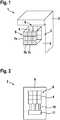
1 ein LIDAR-System gemäß einer ersten Ausführungsform der Erfindung mit einer gemeinsamen Detektormatrix und einer gemeinsamen Filtermatrix, die der Detektormatrix vorgelagert ist;2 eine schematische Draufsicht auf ein gemeinsames Detektorbauteil des LiDAR-Systems gemäß der ersten Ausführungsform der Erfindung;3 eine seitliche Querschnittsansicht durch die Detektormatrix und die Filtermatrix gemäß1 ; und4 eine Draufsicht auf eine alternative Filtermatrix gemäß einer zweiten Ausführungsform der Erfindung.
1 a LIDAR system according to a first embodiment of the invention with a common detector matrix and a common filter matrix, which is upstream of the detector matrix;2nd is a schematic plan view of a common detector component of the LiDAR system according to the first embodiment of the invention;3rd a side cross-sectional view through the detector matrix and the filter matrix according1 ; and4th a plan view of an alternative filter matrix according to a second embodiment of the invention.
Ausführungsformen der ErfindungEmbodiments of the invention
In der
Das in
Das LiDAR-System
Das LiDAR-System 1 ist genauer gesagt dafür eingerichtet, aus Empfangssignalen der Vielzahl von Photodetektoren
Die einzelnen Photodetektoren
Die Photodetektoren
Das Detektorbauteil
Die Photodetektoren
Die Photodetektoren
Die Photodetektoren
Jeder der neun Photodetektoren
Mit anderen Worten zeigt
Jeder Photodetektor
Das LiDAR-System
Auf diese Weise werden ein LiDAR-System
ZITATE ENTHALTEN IN DER BESCHREIBUNG QUOTES INCLUDE IN THE DESCRIPTION
Diese Liste der vom Anmelder aufgeführten Dokumente wurde automatisiert erzeugt und ist ausschließlich zur besseren Information des Lesers aufgenommen. Die Liste ist nicht Bestandteil der deutschen Patent- bzw. Gebrauchsmusteranmeldung. Das DPMA übernimmt keinerlei Haftung für etwaige Fehler oder Auslassungen.This list of documents listed by the applicant has been generated automatically and is only included for the better information of the reader. The list is not part of the German patent or utility model application. The DPMA assumes no liability for any errors or omissions.
Zitierte PatentliteraturPatent literature cited
- US 2017176579 A [0004]US 2017176579 A [0004]
- US 2018003821 A [0005]US 2018003821 A [0005]
- US 2016240579 A1 [0007]US 2016240579 A1 [0007]
- DE 69733014 T2 [0008]DE 69733014 T2 [0008]
- DE 102016211013 A1 [0009]DE 102016211013 A1 [0009]
- DE 102006010295 A1 [0010]DE 102006010295 A1 [0010]
Claims (10)
Translated fromGermanPriority Applications (7)
| Application Number | Priority Date | Filing Date | Title |
|---|---|---|---|
| DE102018221530.8ADE102018221530A1 (en) | 2018-12-12 | 2018-12-12 | LiDAR system and motor vehicle |
| CN201980082298.6ACN113196087A (en) | 2018-12-12 | 2019-12-05 | Laser radar system and motor vehicle |
| PCT/EP2019/083810WO2020120278A1 (en) | 2018-12-12 | 2019-12-05 | Lidar system and motor vehicle |
| KR1020217021247AKR20210096266A (en) | 2018-12-12 | 2019-12-05 | LiDAR systems and automobiles |
| JP2021533443AJP7190576B2 (en) | 2018-12-12 | 2019-12-05 | LiDAR system and automobile |
| US17/286,370US20210381824A1 (en) | 2018-12-12 | 2019-12-05 | Lidar system and motor vehicle |
| EP19816653.0AEP3894884B1 (en) | 2018-12-12 | 2019-12-05 | Lidar system and motor vehicle |
Applications Claiming Priority (1)
| Application Number | Priority Date | Filing Date | Title |
|---|---|---|---|
| DE102018221530.8ADE102018221530A1 (en) | 2018-12-12 | 2018-12-12 | LiDAR system and motor vehicle |
Publications (1)
| Publication Number | Publication Date |
|---|---|
| DE102018221530A1true DE102018221530A1 (en) | 2020-06-18 |
Family
ID=68808374
Family Applications (1)
| Application Number | Title | Priority Date | Filing Date |
|---|---|---|---|
| DE102018221530.8AWithdrawnDE102018221530A1 (en) | 2018-12-12 | 2018-12-12 | LiDAR system and motor vehicle |
Country Status (7)
| Country | Link |
|---|---|
| US (1) | US20210381824A1 (en) |
| EP (1) | EP3894884B1 (en) |
| JP (1) | JP7190576B2 (en) |
| KR (1) | KR20210096266A (en) |
| CN (1) | CN113196087A (en) |
| DE (1) | DE102018221530A1 (en) |
| WO (1) | WO2020120278A1 (en) |
Cited By (2)
| Publication number | Priority date | Publication date | Assignee | Title |
|---|---|---|---|---|
| DE102021201074A1 (en) | 2021-02-05 | 2022-08-11 | Robert Bosch Gesellschaft mit beschränkter Haftung | Detector assembly and optical sensor |
| DE102021202427A1 (en) | 2021-03-12 | 2022-09-15 | Continental Automotive Gmbh | Detector device and sensor unit |
Families Citing this family (1)
| Publication number | Priority date | Publication date | Assignee | Title |
|---|---|---|---|---|
| DE102023206089B4 (en)* | 2023-06-28 | 2025-01-23 | Volkswagen Aktiengesellschaft | Optical sensor, environment recognition system and vehicle |
Citations (8)
| Publication number | Priority date | Publication date | Assignee | Title |
|---|---|---|---|---|
| DE69733014T2 (en) | 1996-04-24 | 2006-02-09 | Leica Geosystems Hds Llc, Oakland | INTEGRATED SYSTEM FOR SHAPING AND MODELING THREE-DIMENSIONAL OBJECTS |
| DE102006010295A1 (en) | 2006-03-07 | 2007-09-13 | Conti Temic Microelectronic Gmbh | Camera system for e.g. motor vehicle, has two different image sensors, whose data are read and merged based on image characteristics to form three-dimensional image, where sensors are sensitive in different spectral regions |
| WO2011015196A1 (en)* | 2009-08-07 | 2011-02-10 | Conti Temic Microelectonic Gmbh | Imaging lidar sensor |
| US20160240579A1 (en) | 2015-02-17 | 2016-08-18 | Omnivision Technologies, Inc. | Stacked embedded spad image sensor for attached 3d information |
| US20170176579A1 (en) | 2015-12-20 | 2017-06-22 | Apple Inc. | Light detection and ranging sensor |
| DE102016211013A1 (en) | 2016-06-21 | 2017-12-21 | Robert Bosch Gmbh | Lidar device and method for analyzing an object |
| US20180003821A1 (en) | 2016-07-01 | 2018-01-04 | Shigeaki Imai | Object detector, sensing device, and mobile apparatus |
| US20180091746A1 (en)* | 2016-09-29 | 2018-03-29 | Honeywell International Inc. | Chip scale multispectral imaging and ranging |
Family Cites Families (17)
| Publication number | Priority date | Publication date | Assignee | Title |
|---|---|---|---|---|
| US20050128509A1 (en)* | 2003-12-11 | 2005-06-16 | Timo Tokkonen | Image creating method and imaging device |
| JP2007526453A (en)* | 2004-01-28 | 2007-09-13 | カネスタ インコーポレイテッド | Single chip red, green, blue, distance (RGB-Z) sensor |
| JP5201825B2 (en)* | 2006-12-13 | 2013-06-05 | 富士フイルム株式会社 | Distance image acquisition apparatus and method |
| WO2010141631A1 (en)* | 2009-06-02 | 2010-12-09 | Velodyne Acoustics, Inc. | Color lidar scanner |
| KR20140092712A (en)* | 2013-01-16 | 2014-07-24 | 삼성전자주식회사 | Sensing Pixel and Image Sensor including Thereof |
| US10126412B2 (en)* | 2013-08-19 | 2018-11-13 | Quanergy Systems, Inc. | Optical phased array lidar system and method of using same |
| US9672398B2 (en)* | 2013-08-26 | 2017-06-06 | Intermec Ip Corporation | Aiming imagers |
| DE102013111547B4 (en)* | 2013-10-21 | 2021-01-21 | Sick Ag | Sensor with a scanning unit that can be moved around the axis of rotation |
| WO2015164117A1 (en)* | 2014-04-21 | 2015-10-29 | Faro Technologies, Inc. | Three-dimensional scanner with dichroic beam splitters to capture a variety of signals |
| CN104181546B (en)* | 2014-08-25 | 2017-01-11 | 中国科学院武汉物理与数学研究所 | Color information acquisition and display method of color three-dimensional scanning laser radar |
| DE102016102610A1 (en)* | 2015-02-13 | 2016-08-18 | Zoller + Fröhlich GmbH | laser scanner |
| JP2016170114A (en)* | 2015-03-13 | 2016-09-23 | 株式会社東芝 | Distance measuring device and photodetector |
| JP6477083B2 (en)* | 2015-03-19 | 2019-03-06 | 株式会社豊田中央研究所 | Optical distance measuring device |
| GB201516701D0 (en)* | 2015-09-21 | 2015-11-04 | Innovation & Business Dev Solutions Ltd | Time of flight distance sensor |
| FR3050831B1 (en)* | 2016-04-29 | 2018-04-27 | Silios Technologies | MULTISPECTRAL IMAGING DEVICE |
| CN110832349B (en)* | 2017-05-15 | 2023-10-10 | 奥斯特公司 | Panoramic color LIDAR system and method for a LIDAR system |
| US10523880B2 (en)* | 2017-09-28 | 2019-12-31 | Waymo Llc | Synchronized spinning LIDAR and rolling shutter camera system |
- 2018
- 2018-12-12DEDE102018221530.8Apatent/DE102018221530A1/ennot_activeWithdrawn
- 2019
- 2019-12-05CNCN201980082298.6Apatent/CN113196087A/enactivePending
- 2019-12-05WOPCT/EP2019/083810patent/WO2020120278A1/ennot_activeCeased
- 2019-12-05EPEP19816653.0Apatent/EP3894884B1/enactiveActive
- 2019-12-05USUS17/286,370patent/US20210381824A1/ennot_activeAbandoned
- 2019-12-05JPJP2021533443Apatent/JP7190576B2/enactiveActive
- 2019-12-05KRKR1020217021247Apatent/KR20210096266A/ennot_activeWithdrawn
Patent Citations (8)
| Publication number | Priority date | Publication date | Assignee | Title |
|---|---|---|---|---|
| DE69733014T2 (en) | 1996-04-24 | 2006-02-09 | Leica Geosystems Hds Llc, Oakland | INTEGRATED SYSTEM FOR SHAPING AND MODELING THREE-DIMENSIONAL OBJECTS |
| DE102006010295A1 (en) | 2006-03-07 | 2007-09-13 | Conti Temic Microelectronic Gmbh | Camera system for e.g. motor vehicle, has two different image sensors, whose data are read and merged based on image characteristics to form three-dimensional image, where sensors are sensitive in different spectral regions |
| WO2011015196A1 (en)* | 2009-08-07 | 2011-02-10 | Conti Temic Microelectonic Gmbh | Imaging lidar sensor |
| US20160240579A1 (en) | 2015-02-17 | 2016-08-18 | Omnivision Technologies, Inc. | Stacked embedded spad image sensor for attached 3d information |
| US20170176579A1 (en) | 2015-12-20 | 2017-06-22 | Apple Inc. | Light detection and ranging sensor |
| DE102016211013A1 (en) | 2016-06-21 | 2017-12-21 | Robert Bosch Gmbh | Lidar device and method for analyzing an object |
| US20180003821A1 (en) | 2016-07-01 | 2018-01-04 | Shigeaki Imai | Object detector, sensing device, and mobile apparatus |
| US20180091746A1 (en)* | 2016-09-29 | 2018-03-29 | Honeywell International Inc. | Chip scale multispectral imaging and ranging |
Cited By (2)
| Publication number | Priority date | Publication date | Assignee | Title |
|---|---|---|---|---|
| DE102021201074A1 (en) | 2021-02-05 | 2022-08-11 | Robert Bosch Gesellschaft mit beschränkter Haftung | Detector assembly and optical sensor |
| DE102021202427A1 (en) | 2021-03-12 | 2022-09-15 | Continental Automotive Gmbh | Detector device and sensor unit |
Also Published As
| Publication number | Publication date |
|---|---|
| JP2022515047A (en) | 2022-02-17 |
| EP3894884A1 (en) | 2021-10-20 |
| WO2020120278A1 (en) | 2020-06-18 |
| EP3894884B1 (en) | 2024-09-04 |
| US20210381824A1 (en) | 2021-12-09 |
| JP7190576B2 (en) | 2022-12-15 |
| CN113196087A (en) | 2021-07-30 |
| KR20210096266A (en) | 2021-08-04 |
Similar Documents
| Publication | Publication Date | Title |
|---|---|---|
| EP3894884B1 (en) | Lidar system and motor vehicle | |
| DE102015110233B4 (en) | An imaging apparatus and method for producing a three-dimensional image of an object | |
| DE69606430T2 (en) | OPTOELECTRONIC SENSOR WITH UNSORTED WHILE READING | |
| DE102017107903A1 (en) | 3D light-time camera and method for acquiring three-dimensional image data | |
| DE60222275T2 (en) | FOCAL LEVEL DETECTOR MATRIX FOR INFRARED RADIATION WITH TWO TIME MULTIPLEX INTEGRATORS AND SUB FRAME AVERAGE FUNCTION PER UNIT CELL | |
| DE112011103229T5 (en) | Color image scanning and reconstruction | |
| DE112019003967T5 (en) | PICTURE CAPTURE DEVICE AND PICTURE CAPTURE SYSTEM | |
| DE102018221083A1 (en) | LiDAR system and motor vehicle | |
| DE102011053219B4 (en) | Combined pixel with phase-sensitive and color-selective sub-pixel | |
| DE102011100350A1 (en) | Image sensor with adjustable resolution | |
| DE102007054314A1 (en) | Circuit arrangement for generating light and temperature-dependent signals, in particular for an imaging pyrometer | |
| DE102012110092A1 (en) | Sensor arrangement for image acquisition | |
| DE3230552C2 (en) | Solid-state color imaging system | |
| DE102023114979A1 (en) | IMAGING SYSTEM WITH SPACIALLY SEPARATE SPECTRAL ARRANGEMENTS | |
| DE102019113597B3 (en) | Pixel array for a camera, camera and time-of-flight camera system with such a camera | |
| DE10220825A1 (en) | Image pickup device for motor vehicle driver assistance system, has image pickup element corresponding to pixel of image detection device | |
| DE2504617C3 (en) | Television camera for generating signals from partial images of a television image | |
| DE102012110094A1 (en) | Image capturing sensor arrangement of image sensor for camera mounted on vehicle, has first type sensing elements which are designed with infrared band elimination filter for electromagnetic radiation in non-visible spectral region | |
| DE102012021736B4 (en) | Image sensor for visible and infrared light and camera system | |
| WO2000066976A2 (en) | Method of recording images and corresponding photogrammetric camera | |
| DE102021201074A1 (en) | Detector assembly and optical sensor | |
| AT512220B1 (en) | METHOD AND A RECORDING APPARATUS FOR RECORDING MULTIPLE PICTURES | |
| DE102023206089B4 (en) | Optical sensor, environment recognition system and vehicle | |
| DE102012014994B4 (en) | Image processing method for a digital stereo camera arrangement | |
| DE112021004403T5 (en) | Sensor arrangement and method for manufacturing a sensor arrangement |
Legal Events
| Date | Code | Title | Description |
|---|---|---|---|
| R163 | Identified publications notified | ||
| R119 | Application deemed withdrawn, or ip right lapsed, due to non-payment of renewal fee |