DE102018219648A1 - Adjustable damping valve device for a vibration damper - Google Patents
Adjustable damping valve device for a vibration damperDownload PDFInfo
- Publication number
- DE102018219648A1 DE102018219648A1DE102018219648.6ADE102018219648ADE102018219648A1DE 102018219648 A1DE102018219648 A1DE 102018219648A1DE 102018219648 ADE102018219648 ADE 102018219648ADE 102018219648 A1DE102018219648 A1DE 102018219648A1
- Authority
- DE
- Germany
- Prior art keywords
- coil arrangement
- valve device
- coil
- yoke body
- holding
- Prior art date
- Legal status (The legal status is an assumption and is not a legal conclusion. Google has not performed a legal analysis and makes no representation as to the accuracy of the status listed.)
- Pending
Links
- 238000013016dampingMethods0.000titleclaimsabstractdescription14
- 230000004907fluxEffects0.000claimsabstractdescription3
- 238000002347injectionMethods0.000claimsdescription9
- 239000007924injectionSubstances0.000claimsdescription9
- 239000000853adhesiveSubstances0.000claimsdescription8
- 230000001070adhesive effectEffects0.000claimsdescription8
- 239000000463materialSubstances0.000claimsdescription3
- 238000004804windingMethods0.000description3
- 239000012790adhesive layerSubstances0.000description2
- 238000004519manufacturing processMethods0.000description2
- BUHVIAUBTBOHAG-FOYDDCNASA-N(2r,3r,4s,5r)-2-[6-[[2-(3,5-dimethoxyphenyl)-2-(2-methylphenyl)ethyl]amino]purin-9-yl]-5-(hydroxymethyl)oxolane-3,4-diolChemical compoundCOC1=CC(OC)=CC(C(CNC=2C=3N=CN(C=3N=CN=2)[C@H]2[C@@H]([C@H](O)[C@@H](CO)O2)O)C=2C(=CC=CC=2)C)=C1BUHVIAUBTBOHAG-FOYDDCNASA-N0.000description1
- 238000004873anchoringMethods0.000description1
- 239000003292glueSubstances0.000description1
- 230000014759maintenance of locationEffects0.000description1
Images


Classifications
- F—MECHANICAL ENGINEERING; LIGHTING; HEATING; WEAPONS; BLASTING
- F16—ENGINEERING ELEMENTS AND UNITS; GENERAL MEASURES FOR PRODUCING AND MAINTAINING EFFECTIVE FUNCTIONING OF MACHINES OR INSTALLATIONS; THERMAL INSULATION IN GENERAL
- F16F—SPRINGS; SHOCK-ABSORBERS; MEANS FOR DAMPING VIBRATION
- F16F9/00—Springs, vibration-dampers, shock-absorbers, or similarly-constructed movement-dampers using a fluid or the equivalent as damping medium
- F16F9/32—Details
- F16F9/3207—Constructional features
- F16F9/3214—Constructional features of pistons
- F—MECHANICAL ENGINEERING; LIGHTING; HEATING; WEAPONS; BLASTING
- F16—ENGINEERING ELEMENTS AND UNITS; GENERAL MEASURES FOR PRODUCING AND MAINTAINING EFFECTIVE FUNCTIONING OF MACHINES OR INSTALLATIONS; THERMAL INSULATION IN GENERAL
- F16F—SPRINGS; SHOCK-ABSORBERS; MEANS FOR DAMPING VIBRATION
- F16F2226/00—Manufacturing; Treatments
- F16F2226/04—Assembly or fixing methods; methods to form or fashion parts
- F—MECHANICAL ENGINEERING; LIGHTING; HEATING; WEAPONS; BLASTING
- F16—ENGINEERING ELEMENTS AND UNITS; GENERAL MEASURES FOR PRODUCING AND MAINTAINING EFFECTIVE FUNCTIONING OF MACHINES OR INSTALLATIONS; THERMAL INSULATION IN GENERAL
- F16F—SPRINGS; SHOCK-ABSORBERS; MEANS FOR DAMPING VIBRATION
- F16F2230/00—Purpose; Design features
- F16F2230/0041—Locking; Fixing in position
- F—MECHANICAL ENGINEERING; LIGHTING; HEATING; WEAPONS; BLASTING
- F16—ENGINEERING ELEMENTS AND UNITS; GENERAL MEASURES FOR PRODUCING AND MAINTAINING EFFECTIVE FUNCTIONING OF MACHINES OR INSTALLATIONS; THERMAL INSULATION IN GENERAL
- F16F—SPRINGS; SHOCK-ABSORBERS; MEANS FOR DAMPING VIBRATION
- F16F2230/00—Purpose; Design features
- F16F2230/0082—Dimensional tolerances, e.g. play between mechanical elements
- F—MECHANICAL ENGINEERING; LIGHTING; HEATING; WEAPONS; BLASTING
- F16—ENGINEERING ELEMENTS AND UNITS; GENERAL MEASURES FOR PRODUCING AND MAINTAINING EFFECTIVE FUNCTIONING OF MACHINES OR INSTALLATIONS; THERMAL INSULATION IN GENERAL
- F16F—SPRINGS; SHOCK-ABSORBERS; MEANS FOR DAMPING VIBRATION
- F16F9/00—Springs, vibration-dampers, shock-absorbers, or similarly-constructed movement-dampers using a fluid or the equivalent as damping medium
- F16F9/10—Springs, vibration-dampers, shock-absorbers, or similarly-constructed movement-dampers using a fluid or the equivalent as damping medium using liquid only; using a fluid of which the nature is immaterial
- F16F9/14—Devices with one or more members, e.g. pistons, vanes, moving to and fro in chambers and using throttling effect
- F16F9/16—Devices with one or more members, e.g. pistons, vanes, moving to and fro in chambers and using throttling effect involving only straight-line movement of the effective parts
- F16F9/18—Devices with one or more members, e.g. pistons, vanes, moving to and fro in chambers and using throttling effect involving only straight-line movement of the effective parts with a closed cylinder and a piston separating two or more working spaces therein
- F—MECHANICAL ENGINEERING; LIGHTING; HEATING; WEAPONS; BLASTING
- F16—ENGINEERING ELEMENTS AND UNITS; GENERAL MEASURES FOR PRODUCING AND MAINTAINING EFFECTIVE FUNCTIONING OF MACHINES OR INSTALLATIONS; THERMAL INSULATION IN GENERAL
- F16F—SPRINGS; SHOCK-ABSORBERS; MEANS FOR DAMPING VIBRATION
- F16F9/00—Springs, vibration-dampers, shock-absorbers, or similarly-constructed movement-dampers using a fluid or the equivalent as damping medium
- F16F9/32—Details
- F16F9/44—Means on or in the damper for manual or non-automatic adjustment; such means combined with temperature correction
- F16F9/46—Means on or in the damper for manual or non-automatic adjustment; such means combined with temperature correction allowing control from a distance, i.e. location of means for control input being remote from site of valves, e.g. on damper external wall
Landscapes
- Engineering & Computer Science (AREA)
- General Engineering & Computer Science (AREA)
- Mechanical Engineering (AREA)
- Magnetically Actuated Valves (AREA)
Abstract
Translated fromGermanDescription
Translated fromGermanDie Erfindung betrifft eine verstellbare Dämpfventileinrichtung, insbesondere für einen Schwingungsdämpfer, gemäß dem Oberbegriff von Patentanspruch 1.The invention relates to an adjustable damping valve device, in particular for a vibration damper, according to the preamble of
Eine verstellbare Dämpfventileinrichtung enthält einige Einzelteile, u. a. das eigentliche verstellbare Dämpfventil und vielfach einen elektromagnetischen Aktuator. Der Aktuator wiederum weist eine Magnetspule und einen Rückschlusskörper auf. Während des Schwingungsdämpferbetriebs können Geräusche auftreten, die auch im Fahrzeug vernehmbar sind. Aus der
Trotzdem treten unter bestimmten Bedingungen noch Geräusche auf, die als störend empfunden werden.Nevertheless, under certain conditions there are still noises that are perceived as annoying.
Die Aufgabe der vorliegenden Erfindung besteht darin, die Geräuschemission weiter zu verbessern.The object of the present invention is to further improve the noise emission.
Die Aufgabe wird dadurch gelöst, dass die Spulenanordnung mit dem Rückschlusskörper eine radial spielfreie Halteverbindung bildet.The object is achieved in that the coil arrangement forms a radially backlash-free holding connection with the yoke body.
Der Rückschlusskörper dient der Spulenanordnung als Verankerungselement zum Ventilgehäuse. Auch bei stärkeren Schwingungen werden damit alle hörbaren Relativbewegungen zwischen der Spulenanordnung und dem Ventilgehäuse unterbunden.The yoke body serves the coil arrangement as an anchoring element to the valve housing. Even with strong vibrations, all audible relative movements between the coil arrangement and the valve housing are prevented.
In der einfachsten Form wird die Halteverbindung von einem Pressverband zwischen der Spulenanordnung und dem Rückschlusskörper gebildet. Die Spulenanordnung verfügt über einen Spulenträger aus Kunststoff, der sich bei der Pressverbindung geringfügig deformieren kann.In the simplest form, the holding connection is formed by a press fit between the coil arrangement and the yoke body. The coil arrangement has a coil carrier made of plastic, which can deform slightly during the press connection.
Alternativ oder zusätzlich kann die Halteverbindung als eine stoffschlüssige Verbindung zwischen der Spulenanordnung und dem Rückschlusskörper ausgeführt sein. Damit kann zwischen den beiden Bauteilen eine großflächige Haltverbindung vorliegen.Alternatively or additionally, the holding connection can be embodied as a material connection between the coil arrangement and the yoke body. A large-area retention connection can thus be present between the two components.
Gemäß einem vorteilhaften Unteranspruch weist die Spulenanordnung einen Spulendom auf, der den Rückschlusskörper in einer Halteöffnung durchdringt, wobei der Spulendom und/oder eine Mantelfläche der Halteöffnung mit Klemmflächen versehen ist. Damit wird auch eine radiale Positionierung der Spulenanordnung zum Rückschlusskörper erreicht.According to an advantageous subclaim, the coil arrangement has a coil dome which penetrates the yoke body in a holding opening, the coil dome and / or an outer surface of the holding opening being provided with clamping surfaces. This also achieves a radial positioning of the coil arrangement with respect to the yoke body.
Des Weiteren oder alternativ kann die Spulenanordnung eine Querbrücke aufweisen, die in eine Quernut des Rückschlusskörpers eingreift, wobei die Querbrücke und die Quernut Halteflächen für die Halteverbindung aufweisen. Damit liegen vergleichsweise große Halteflächen vor.Furthermore or alternatively, the coil arrangement can have a transverse bridge which engages in a transverse groove of the yoke body, the transverse bridge and the transverse groove having holding surfaces for the holding connection. This means that there are comparatively large holding areas.
Vorteilhafterweise bildet die Quernut eine Aufnahme für Klebervolumen. Die Kombination einer Quernut mit der Querbrücke führt zu einem Klebespalt mit definierter Klebeschichtstärke. Eine definierte Klebeschichtstärke erhöht die Qualität einer Klebeverbindung.The transverse groove advantageously forms a receptacle for the adhesive volume. The combination of a transverse groove with the transverse bridge leads to an adhesive gap with a defined adhesive layer thickness. A defined adhesive layer thickness increases the quality of an adhesive connection.
Des Weiteren kann man vorsehen, dass ein Ringspalt zwischen der Spulenanordnung und dem Ventilgehäuse über einen Einspritzkanal im Ventilgehäuse mit Klebstoff füllbar ist. Die bereits im Ventilgehäuse montierte Spulenanordnung kann mit dem Ventilgehäuse verklebt werden.Furthermore, it can be provided that an annular gap between the coil arrangement and the valve housing can be filled with adhesive via an injection channel in the valve housing. The coil assembly already installed in the valve housing can be glued to the valve housing.
Bevorzugt verläuft der Einspritzkanal durch den Rückschlusskörper. Der Einspritzkanal lässt sich im Rahmen des Fertigungsprozesses einfach herstellen und vor allem einfach entgraten, sodass keine Gefahr von Spänen innerhalb der Ventileinrichtung besteht.The injection channel preferably runs through the yoke body. The injection channel is easy to manufacture as part of the manufacturing process and, above all, easy to deburr, so that there is no risk of chips inside the valve device.
Anhand der folgenden Figurenbeschreibung soll die Erfindung näher erläutert werden.The invention will be explained in more detail with reference to the following description of the figures.
Es zeigt:
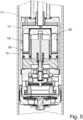
1 Schnittdarstellung durch eine Dämpfventileinrichtung2 und4 Ansichten vom Rückschlusskörpern3 Rückschlusskörper mit Spulenanordnung5 Verklebte Spulenanordnung im Ventilgehäuse
1 Sectional view through a damping valve device2nd and4th Views from the inference body3rd Inference body with coil arrangement5 Glued coil arrangement in the valve housing
Die
Der Aktuator
Auch die Spulenanordnung
Die Halteverbindung
Die Spulenanordnung
Wie insbesondere die Zusammenschau der
Die Halteverbindung
Die Quernut
Bei der Montage wird der Rückschlusskörper
Zusätzlich oder alternativ kann man vorsehen, dass ein Ringspalt
BezugszeichenlisteReference symbol list
- 11
- DämpfventileinrichtungDamping valve device
- 33rd
- KolbenstangePiston rod
- 55
- SchwingungsdämpferVibration damper
- 77
- AktuatorActuator
- 99
- DämpfventilDamping valve
- 1111
- HauptstufenventilMain stage valve
- 1313
- SpulenanordnungCoil arrangement
- 1515
- VentilgehäuseValve body
- 1717th
- RückschlusskörperInference body
- 1919th
- HalteverbindungStop connection
- 2121st
- SpulendomCoil dome
- 2323
- SpulenträgerCoil carrier
- 2525th
- HalteöffnungHolding opening
- 2727th
- MantelflächeLateral surface
- 2929
- KlemmflächeClamping surface
- 3131
- AufnahmenutGroove
- 3333
- SpulenwicklungCoil winding
- 3535
- QuerbrückeCross bridge
- 3737
- QuernutCross groove
- 3939
- RingspaltAnnular gap
- 4141
- EinspritzkanalInjection channel
- 4343
- Mantelfläche des VentilgehäusesLateral surface of the valve housing
ZITATE ENTHALTEN IN DER BESCHREIBUNG QUOTES INCLUDE IN THE DESCRIPTION
Diese Liste der vom Anmelder aufgeführten Dokumente wurde automatisiert erzeugt und ist ausschließlich zur besseren Information des Lesers aufgenommen. Die Liste ist nicht Bestandteil der deutschen Patent- bzw. Gebrauchsmusteranmeldung. Das DPMA übernimmt keinerlei Haftung für etwaige Fehler oder Auslassungen.This list of documents listed by the applicant has been generated automatically and is only included for the better information of the reader. The list is not part of the German patent or utility model application. The DPMA assumes no liability for any errors or omissions.
Zitierte PatentliteraturPatent literature cited
- DE 102016205651 A1 [0002, 0024]DE 102016205651 A1 [0002, 0024]
- DE 102015223932 A1 [0016]DE 102015223932 A1 [0016]
Claims (8)
Translated fromGermanPriority Applications (1)
| Application Number | Priority Date | Filing Date | Title |
|---|---|---|---|
| DE102018219648.6ADE102018219648A1 (en) | 2018-11-16 | 2018-11-16 | Adjustable damping valve device for a vibration damper |
Applications Claiming Priority (1)
| Application Number | Priority Date | Filing Date | Title |
|---|---|---|---|
| DE102018219648.6ADE102018219648A1 (en) | 2018-11-16 | 2018-11-16 | Adjustable damping valve device for a vibration damper |
Publications (1)
| Publication Number | Publication Date |
|---|---|
| DE102018219648A1true DE102018219648A1 (en) | 2020-05-20 |
Family
ID=70470558
Family Applications (1)
| Application Number | Title | Priority Date | Filing Date |
|---|---|---|---|
| DE102018219648.6APendingDE102018219648A1 (en) | 2018-11-16 | 2018-11-16 | Adjustable damping valve device for a vibration damper |
Country Status (1)
| Country | Link |
|---|---|
| DE (1) | DE102018219648A1 (en) |
Citations (7)
| Publication number | Priority date | Publication date | Assignee | Title |
|---|---|---|---|---|
| US6035979A (en)* | 1996-06-21 | 2000-03-14 | Fichtel & Sachs Ag | Vibration damper and a vibration damper with a damping valve having an adjustable damping force |
| DE102009059808A1 (en)* | 2009-12-21 | 2011-06-22 | ZF Friedrichshafen AG, 88046 | Adjustable damping valve |
| DE102011003924B4 (en)* | 2011-02-10 | 2015-01-08 | Zf Friedrichshafen Ag | Adjustable damping valve for a vibration damper |
| EP2975292A1 (en)* | 2013-03-13 | 2016-01-20 | KYB Corporation | Damping valve |
| DE102014215199A1 (en)* | 2014-08-01 | 2016-02-04 | Zf Friedrichshafen Ag | Adjustable damper valve device |
| DE102015223932A1 (en) | 2015-12-01 | 2017-06-01 | Zf Friedrichshafen Ag | Adjustable damper valve device with a damping valve |
| DE102016205651A1 (en) | 2016-04-06 | 2017-10-12 | Zf Friedrichshafen Ag | Adjustable damper valve device for a vibration damper |
- 2018
- 2018-11-16DEDE102018219648.6Apatent/DE102018219648A1/enactivePending
Patent Citations (7)
| Publication number | Priority date | Publication date | Assignee | Title |
|---|---|---|---|---|
| US6035979A (en)* | 1996-06-21 | 2000-03-14 | Fichtel & Sachs Ag | Vibration damper and a vibration damper with a damping valve having an adjustable damping force |
| DE102009059808A1 (en)* | 2009-12-21 | 2011-06-22 | ZF Friedrichshafen AG, 88046 | Adjustable damping valve |
| DE102011003924B4 (en)* | 2011-02-10 | 2015-01-08 | Zf Friedrichshafen Ag | Adjustable damping valve for a vibration damper |
| EP2975292A1 (en)* | 2013-03-13 | 2016-01-20 | KYB Corporation | Damping valve |
| DE102014215199A1 (en)* | 2014-08-01 | 2016-02-04 | Zf Friedrichshafen Ag | Adjustable damper valve device |
| DE102015223932A1 (en) | 2015-12-01 | 2017-06-01 | Zf Friedrichshafen Ag | Adjustable damper valve device with a damping valve |
| DE102016205651A1 (en) | 2016-04-06 | 2017-10-12 | Zf Friedrichshafen Ag | Adjustable damper valve device for a vibration damper |
Similar Documents
| Publication | Publication Date | Title |
|---|---|---|
| DE102010015712A1 (en) | Suspension strut bearing and method of manufacturing a suspension strut bearing component | |
| DE2515234A1 (en) | MICROPHONE HOLDER | |
| DE2705690A1 (en) | VEHICLE HANGING DEVICE | |
| DE102011102700A1 (en) | Pneumatic valve unit | |
| DE102012209859A1 (en) | Valve unit with axial pressure medium inflow | |
| DE102013100126A1 (en) | Electromagnetic valve | |
| DE102007043552A1 (en) | Solenoid valve | |
| DE102014205855A1 (en) | Dämpfventilanordnung with a multi-level damping force curve | |
| DE102004013169A1 (en) | Fuel injection valve | |
| EP2636920A2 (en) | Adjustable muffler valve | |
| DE102015016454A1 (en) | Elastic bearing | |
| DE102010025372A1 (en) | Suspension strut bearing for rotatably supporting e.g. shock absorber of front axle system opposite to body of two-track vehicle, has spring support and guide ring with resilient seal lip that grindingly cooperates with rotating edge of cap | |
| DE102010038506A1 (en) | Valve arrangement for slippage-regular motor car brake assemblies, has wall portion penetrated into housing passage for noticing function of pressure medium passage that is designed as valve seat for non return valve | |
| DE102018219648A1 (en) | Adjustable damping valve device for a vibration damper | |
| DE102019211385A1 (en) | Vibration damper with a hydraulic end stop | |
| DE102012011627A1 (en) | Magnetic valve, has coil partially surrounded by coil body, non-cutting widened regions placed at outer side of coil body, and core axially extended from middle part of coil to bottom part of pot-shaped deck element | |
| DE3147708A1 (en) | CHECK VALVE OF A VEHICLE BRAKE POWER AMPLIFIER | |
| DE102008024101A1 (en) | Valve arrangement, particularly for slip-controlled motor vehicle-brake system, has hydraulically controllable check valve in check valve housing and valve closing element controllable by armature and magnetic coil in electromagnetic manner | |
| DE102009049244A1 (en) | Damping device for damping of pressure oscillations in hydraulic line, has branch circuit whose attachment piece is connected with another attachment piece of container | |
| DE102007014247B4 (en) | Vibration damper with a stroke-dependent stop spring | |
| DE102016221931A1 (en) | Magnetic assembly and fuel injector with a magnetic assembly | |
| DE102007004254A1 (en) | Electromagnetic actuator | |
| DE102019203898A1 (en) | Adjustable damper valve device | |
| DE102019200995A1 (en) | Arrangement for storing an assembly in a motor vehicle and motor vehicle with such a storage arrangement | |
| DE102010023993A1 (en) | Electrical noise absorber for electric cable, has sleeve that rests against surface of end region of intermediate connector so that gap formed between sleeve and annular element is sealed by lock washer/sealing ring |
Legal Events
| Date | Code | Title | Description |
|---|---|---|---|
| R079 | Amendment of ipc main class | Free format text:PREVIOUS MAIN CLASS: F16F0009460000 Ipc:F16F0009340000 | |
| R163 | Identified publications notified |