DE102018217080A1 - Method and device for preparing an inductive energy transfer from a charging station to a vehicle - Google Patents
Method and device for preparing an inductive energy transfer from a charging station to a vehicleDownload PDFInfo
- Publication number
- DE102018217080A1 DE102018217080A1DE102018217080.0ADE102018217080ADE102018217080A1DE 102018217080 A1DE102018217080 A1DE 102018217080A1DE 102018217080 ADE102018217080 ADE 102018217080ADE 102018217080 A1DE102018217080 A1DE 102018217080A1
- Authority
- DE
- Germany
- Prior art keywords
- vehicle
- charging station
- signal
- identifier
- coil
- Prior art date
- Legal status (The legal status is an assumption and is not a legal conclusion. Google has not performed a legal analysis and makes no representation as to the accuracy of the status listed.)
- Ceased
Links
Images
Classifications
- G—PHYSICS
- G01—MEASURING; TESTING
- G01S—RADIO DIRECTION-FINDING; RADIO NAVIGATION; DETERMINING DISTANCE OR VELOCITY BY USE OF RADIO WAVES; LOCATING OR PRESENCE-DETECTING BY USE OF THE REFLECTION OR RERADIATION OF RADIO WAVES; ANALOGOUS ARRANGEMENTS USING OTHER WAVES
- G01S7/00—Details of systems according to groups G01S13/00, G01S15/00, G01S17/00
- G01S7/02—Details of systems according to groups G01S13/00, G01S15/00, G01S17/00 of systems according to group G01S13/00
- G01S7/41—Details of systems according to groups G01S13/00, G01S15/00, G01S17/00 of systems according to group G01S13/00 using analysis of echo signal for target characterisation; Target signature; Target cross-section
- G01S7/411—Identification of targets based on measurements of radar reflectivity
- G01S7/412—Identification of targets based on measurements of radar reflectivity based on a comparison between measured values and known or stored values
- B—PERFORMING OPERATIONS; TRANSPORTING
- B60—VEHICLES IN GENERAL
- B60L—PROPULSION OF ELECTRICALLY-PROPELLED VEHICLES; SUPPLYING ELECTRIC POWER FOR AUXILIARY EQUIPMENT OF ELECTRICALLY-PROPELLED VEHICLES; ELECTRODYNAMIC BRAKE SYSTEMS FOR VEHICLES IN GENERAL; MAGNETIC SUSPENSION OR LEVITATION FOR VEHICLES; MONITORING OPERATING VARIABLES OF ELECTRICALLY-PROPELLED VEHICLES; ELECTRIC SAFETY DEVICES FOR ELECTRICALLY-PROPELLED VEHICLES
- B60L53/00—Methods of charging batteries, specially adapted for electric vehicles; Charging stations or on-board charging equipment therefor; Exchange of energy storage elements in electric vehicles
- B60L53/10—Methods of charging batteries, specially adapted for electric vehicles; Charging stations or on-board charging equipment therefor; Exchange of energy storage elements in electric vehicles characterised by the energy transfer between the charging station and the vehicle
- B60L53/12—Inductive energy transfer
- B60L53/124—Detection or removal of foreign bodies
- B—PERFORMING OPERATIONS; TRANSPORTING
- B60—VEHICLES IN GENERAL
- B60L—PROPULSION OF ELECTRICALLY-PROPELLED VEHICLES; SUPPLYING ELECTRIC POWER FOR AUXILIARY EQUIPMENT OF ELECTRICALLY-PROPELLED VEHICLES; ELECTRODYNAMIC BRAKE SYSTEMS FOR VEHICLES IN GENERAL; MAGNETIC SUSPENSION OR LEVITATION FOR VEHICLES; MONITORING OPERATING VARIABLES OF ELECTRICALLY-PROPELLED VEHICLES; ELECTRIC SAFETY DEVICES FOR ELECTRICALLY-PROPELLED VEHICLES
- B60L53/00—Methods of charging batteries, specially adapted for electric vehicles; Charging stations or on-board charging equipment therefor; Exchange of energy storage elements in electric vehicles
- B60L53/10—Methods of charging batteries, specially adapted for electric vehicles; Charging stations or on-board charging equipment therefor; Exchange of energy storage elements in electric vehicles characterised by the energy transfer between the charging station and the vehicle
- B60L53/12—Inductive energy transfer
- B60L53/126—Methods for pairing a vehicle and a charging station, e.g. establishing a one-to-one relation between a wireless power transmitter and a wireless power receiver
- B—PERFORMING OPERATIONS; TRANSPORTING
- B60—VEHICLES IN GENERAL
- B60L—PROPULSION OF ELECTRICALLY-PROPELLED VEHICLES; SUPPLYING ELECTRIC POWER FOR AUXILIARY EQUIPMENT OF ELECTRICALLY-PROPELLED VEHICLES; ELECTRODYNAMIC BRAKE SYSTEMS FOR VEHICLES IN GENERAL; MAGNETIC SUSPENSION OR LEVITATION FOR VEHICLES; MONITORING OPERATING VARIABLES OF ELECTRICALLY-PROPELLED VEHICLES; ELECTRIC SAFETY DEVICES FOR ELECTRICALLY-PROPELLED VEHICLES
- B60L53/00—Methods of charging batteries, specially adapted for electric vehicles; Charging stations or on-board charging equipment therefor; Exchange of energy storage elements in electric vehicles
- B60L53/30—Constructional details of charging stations
- B60L53/35—Means for automatic or assisted adjustment of the relative position of charging devices and vehicles
- B60L53/38—Means for automatic or assisted adjustment of the relative position of charging devices and vehicles specially adapted for charging by inductive energy transfer
- G—PHYSICS
- G01—MEASURING; TESTING
- G01S—RADIO DIRECTION-FINDING; RADIO NAVIGATION; DETERMINING DISTANCE OR VELOCITY BY USE OF RADIO WAVES; LOCATING OR PRESENCE-DETECTING BY USE OF THE REFLECTION OR RERADIATION OF RADIO WAVES; ANALOGOUS ARRANGEMENTS USING OTHER WAVES
- G01S13/00—Systems using the reflection or reradiation of radio waves, e.g. radar systems; Analogous systems using reflection or reradiation of waves whose nature or wavelength is irrelevant or unspecified
- G01S13/87—Combinations of radar systems, e.g. primary radar and secondary radar
- G01S13/878—Combination of several spaced transmitters or receivers of known location for determining the position of a transponder or a reflector
- G—PHYSICS
- G06—COMPUTING OR CALCULATING; COUNTING
- G06K—GRAPHICAL DATA READING; PRESENTATION OF DATA; RECORD CARRIERS; HANDLING RECORD CARRIERS
- G06K19/00—Record carriers for use with machines and with at least a part designed to carry digital markings
- G06K19/06—Record carriers for use with machines and with at least a part designed to carry digital markings characterised by the kind of the digital marking, e.g. shape, nature, code
- G06K19/06009—Record carriers for use with machines and with at least a part designed to carry digital markings characterised by the kind of the digital marking, e.g. shape, nature, code with optically detectable marking
- G06K19/06037—Record carriers for use with machines and with at least a part designed to carry digital markings characterised by the kind of the digital marking, e.g. shape, nature, code with optically detectable marking multi-dimensional coding
- G—PHYSICS
- G06—COMPUTING OR CALCULATING; COUNTING
- G06K—GRAPHICAL DATA READING; PRESENTATION OF DATA; RECORD CARRIERS; HANDLING RECORD CARRIERS
- G06K7/00—Methods or arrangements for sensing record carriers, e.g. for reading patterns
- G06K7/10—Methods or arrangements for sensing record carriers, e.g. for reading patterns by electromagnetic radiation, e.g. optical sensing; by corpuscular radiation
- G06K7/10009—Methods or arrangements for sensing record carriers, e.g. for reading patterns by electromagnetic radiation, e.g. optical sensing; by corpuscular radiation sensing by radiation using wavelengths larger than 0.1 mm, e.g. radio-waves or microwaves
- H—ELECTRICITY
- H02—GENERATION; CONVERSION OR DISTRIBUTION OF ELECTRIC POWER
- H02J—CIRCUIT ARRANGEMENTS OR SYSTEMS FOR SUPPLYING OR DISTRIBUTING ELECTRIC POWER; SYSTEMS FOR STORING ELECTRIC ENERGY
- H02J50/00—Circuit arrangements or systems for wireless supply or distribution of electric power
- H02J50/10—Circuit arrangements or systems for wireless supply or distribution of electric power using inductive coupling
- H—ELECTRICITY
- H02—GENERATION; CONVERSION OR DISTRIBUTION OF ELECTRIC POWER
- H02J—CIRCUIT ARRANGEMENTS OR SYSTEMS FOR SUPPLYING OR DISTRIBUTING ELECTRIC POWER; SYSTEMS FOR STORING ELECTRIC ENERGY
- H02J50/00—Circuit arrangements or systems for wireless supply or distribution of electric power
- H02J50/80—Circuit arrangements or systems for wireless supply or distribution of electric power involving the exchange of data, concerning supply or distribution of electric power, between transmitting devices and receiving devices
- H—ELECTRICITY
- H02—GENERATION; CONVERSION OR DISTRIBUTION OF ELECTRIC POWER
- H02J—CIRCUIT ARRANGEMENTS OR SYSTEMS FOR SUPPLYING OR DISTRIBUTING ELECTRIC POWER; SYSTEMS FOR STORING ELECTRIC ENERGY
- H02J50/00—Circuit arrangements or systems for wireless supply or distribution of electric power
- H02J50/90—Circuit arrangements or systems for wireless supply or distribution of electric power involving detection or optimisation of position, e.g. alignment
- H—ELECTRICITY
- H02—GENERATION; CONVERSION OR DISTRIBUTION OF ELECTRIC POWER
- H02J—CIRCUIT ARRANGEMENTS OR SYSTEMS FOR SUPPLYING OR DISTRIBUTING ELECTRIC POWER; SYSTEMS FOR STORING ELECTRIC ENERGY
- H02J7/00—Circuit arrangements for charging or depolarising batteries or for supplying loads from batteries
- H02J7/00032—Circuit arrangements for charging or depolarising batteries or for supplying loads from batteries characterised by data exchange
- H02J7/00036—Charger exchanging data with battery
- Y—GENERAL TAGGING OF NEW TECHNOLOGICAL DEVELOPMENTS; GENERAL TAGGING OF CROSS-SECTIONAL TECHNOLOGIES SPANNING OVER SEVERAL SECTIONS OF THE IPC; TECHNICAL SUBJECTS COVERED BY FORMER USPC CROSS-REFERENCE ART COLLECTIONS [XRACs] AND DIGESTS
- Y02—TECHNOLOGIES OR APPLICATIONS FOR MITIGATION OR ADAPTATION AGAINST CLIMATE CHANGE
- Y02T—CLIMATE CHANGE MITIGATION TECHNOLOGIES RELATED TO TRANSPORTATION
- Y02T10/00—Road transport of goods or passengers
- Y02T10/60—Other road transportation technologies with climate change mitigation effect
- Y02T10/70—Energy storage systems for electromobility, e.g. batteries
- Y—GENERAL TAGGING OF NEW TECHNOLOGICAL DEVELOPMENTS; GENERAL TAGGING OF CROSS-SECTIONAL TECHNOLOGIES SPANNING OVER SEVERAL SECTIONS OF THE IPC; TECHNICAL SUBJECTS COVERED BY FORMER USPC CROSS-REFERENCE ART COLLECTIONS [XRACs] AND DIGESTS
- Y02—TECHNOLOGIES OR APPLICATIONS FOR MITIGATION OR ADAPTATION AGAINST CLIMATE CHANGE
- Y02T—CLIMATE CHANGE MITIGATION TECHNOLOGIES RELATED TO TRANSPORTATION
- Y02T10/00—Road transport of goods or passengers
- Y02T10/60—Other road transportation technologies with climate change mitigation effect
- Y02T10/7072—Electromobility specific charging systems or methods for batteries, ultracapacitors, supercapacitors or double-layer capacitors
- Y—GENERAL TAGGING OF NEW TECHNOLOGICAL DEVELOPMENTS; GENERAL TAGGING OF CROSS-SECTIONAL TECHNOLOGIES SPANNING OVER SEVERAL SECTIONS OF THE IPC; TECHNICAL SUBJECTS COVERED BY FORMER USPC CROSS-REFERENCE ART COLLECTIONS [XRACs] AND DIGESTS
- Y02—TECHNOLOGIES OR APPLICATIONS FOR MITIGATION OR ADAPTATION AGAINST CLIMATE CHANGE
- Y02T—CLIMATE CHANGE MITIGATION TECHNOLOGIES RELATED TO TRANSPORTATION
- Y02T90/00—Enabling technologies or technologies with a potential or indirect contribution to GHG emissions mitigation
- Y02T90/10—Technologies relating to charging of electric vehicles
- Y02T90/12—Electric charging stations
- Y—GENERAL TAGGING OF NEW TECHNOLOGICAL DEVELOPMENTS; GENERAL TAGGING OF CROSS-SECTIONAL TECHNOLOGIES SPANNING OVER SEVERAL SECTIONS OF THE IPC; TECHNICAL SUBJECTS COVERED BY FORMER USPC CROSS-REFERENCE ART COLLECTIONS [XRACs] AND DIGESTS
- Y02—TECHNOLOGIES OR APPLICATIONS FOR MITIGATION OR ADAPTATION AGAINST CLIMATE CHANGE
- Y02T—CLIMATE CHANGE MITIGATION TECHNOLOGIES RELATED TO TRANSPORTATION
- Y02T90/00—Enabling technologies or technologies with a potential or indirect contribution to GHG emissions mitigation
- Y02T90/10—Technologies relating to charging of electric vehicles
- Y02T90/14—Plug-in electric vehicles
Landscapes
- Engineering & Computer Science (AREA)
- Power Engineering (AREA)
- Computer Networks & Wireless Communication (AREA)
- Physics & Mathematics (AREA)
- Radar, Positioning & Navigation (AREA)
- Remote Sensing (AREA)
- General Physics & Mathematics (AREA)
- Mechanical Engineering (AREA)
- Transportation (AREA)
- Theoretical Computer Science (AREA)
- Health & Medical Sciences (AREA)
- Toxicology (AREA)
- Electromagnetism (AREA)
- General Health & Medical Sciences (AREA)
- Artificial Intelligence (AREA)
- Computer Vision & Pattern Recognition (AREA)
- Charge And Discharge Circuits For Batteries Or The Like (AREA)
Abstract
Translated fromGermanDescription
Translated fromGermanDie Erfindung betrifft ein Verfahren und eine Vorrichtung zur Vorbereitung einer induktiven Energieübertragung von einer Ladestation an ein Fahrzeug. Diese Energieübertragung kann zur Ladung eines Energiespeichers des Fahrzeugs und/oder zur Versorgung von elektrischen Verbrauchern des Fahrzeugs vorgesehen sein.The invention relates to a method and a device for preparing an inductive energy transmission from a charging station to a vehicle. This energy transfer can be provided for charging an energy store of the vehicle and / or for supplying electrical consumers of the vehicle.
Eine induktive Energieübertragung von einer Ladestation an ein Fahrzeug erfolgt drahtlos unter Verwendung eines der Ladestation zugehörigen Senders und eines dem Fahrzeug zugehörigen Empfängers. Der Sender weist üblicherweise eine Bodenplatte auf, innerhalb welcher eine Spule vorgesehen ist, unter deren Verwendung ein magnetisches Wechselmagnetfeld ausgestrahlt wird. Dieses wird von einem oberhalb der Bodenplatte angeordneten fahrzeugseitigen Empfänger empfangen und in Gleichstromsignale umgewandelt, die beispielsweise zur Aufladung einer fahrzeugseitigen Batterie verwendet werden.Inductive energy transmission from a charging station to a vehicle takes place wirelessly using a transmitter belonging to the charging station and a receiver belonging to the vehicle. The transmitter usually has a base plate within which a coil is provided, using which a magnetic alternating magnetic field is emitted. This is received by a vehicle-side receiver arranged above the base plate and converted into direct current signals which are used, for example, to charge a vehicle-side battery.
Um diese Energieübertragung bestmöglich zu gestalten, ist es notwendig, verschiedene Vorbereitungsmaßnahmen durchzuführen. Zu diesen Vorbereitungsmaßnahmen gehört eine möglichst genaue Positionierung des fahrzeugseitigen Empfängers über der Spule der Bodenplatte. Zu diesen Vorbereitungsmaßnahmen gehört des Weiteren eine Überprüfung, ob der Zwischenraum zwischen der Bodenplatte und dem fahrzeugseitigen Empfänger frei von Objekten ist. Zu diesen Objekten gehören beliebige Gegenstände und auch beliebige Lebewesen. Bei dieser Objekterkennung kann eine Bewegungsdetektion vorgenommen werden.In order to make this energy transfer as good as possible, it is necessary to carry out various preparatory measures. These preparatory measures include positioning the receiver on the vehicle as precisely as possible above the coil of the base plate. These preparatory measures also include checking whether the space between the base plate and the vehicle-side receiver is free of objects. These objects include any objects and also any living things. With this object detection, motion detection can be carried out.
Aus der
Die Aufgabe der Erfindung besteht darin, ein verbessertes Verfahren zur Vorbereitung einer induktiven Energieübertragung von einer Ladestation an ein Fahrzeug anzugeben.The object of the invention is to provide an improved method for preparing an inductive energy transmission from a charging station to a vehicle.
Diese Aufgabe wird durch ein Verfahren mit den in Anspruch 1 angegebenen Merkmalen gelöst. Vorteilhafte Ausgestaltungen und Weiterbildungen der Erfindung sind in den abhängigen Ansprüchen 2 - 12 angegeben. Die Ansprüche 13 - 15 betreffen eine Vorrichtung zur Vorbereitung einer induktiven Energieübertragung von einer Ladestation an ein Fahrzeug.This object is achieved by a method with the features specified in
Gemäß der Erfindung wird ein Verfahren zur Vorbereitung einer induktiven Energieübertragung von einer Ladestation an ein Fahrzeug bereitgestellt, bei welchem die folgenden Schritte durchgeführt werden:
- - Ausstrahlen eines elektromagnetischen Signals mittels einer in einer Bodenplatte der Ladestation angeordneten Spule,
- - Empfangen des mittels der Spule der Bodenplatte ausgestrahlten Signals vom Fahrzeug,
- - Ausstrahlen eines Antwortsignals vom Fahrzeug an einen in der Bodenplatte angeordneten Empfänger,
- - Empfangen des vom Fahrzeug ausgestrahlten Antwortsignals mittels des in der Bodenplatte angeordneten Empfängers und
- - Auswerten des vom in der Bodenplatte angeordneten Empfänger empfangenen Antwortsignals,
- - wobei das von der Spule ausgestrahlte elektromagnetische Signal an einer am Fahrzeug angebrachten Kennung reflektiert wird und das reflektierte Signal als Antwortsignal an die Ladestation übertragen wird und
- - wobei die Kennung ein geometrisches Muster enthält.
- Emitting an electromagnetic signal by means of a coil arranged in a bottom plate of the charging station,
- Receiving the signal emitted by the coil of the floor panel from the vehicle,
- Emitting a response signal from the vehicle to a receiver located in the bottom plate,
- Receiving the emitted by the vehicle response signal by means of the arranged in the bottom plate receiver and
- Evaluating the response signal received from the receiver located in the bottom plate,
- - Wherein the electromagnetic signal emitted by the coil is reflected at a vehicle-mounted identifier and the reflected signal is transmitted as a response signal to the charging station, and
- - wherein the identifier includes a geometric pattern.
Die Vorteile der Erfindung beruhen insbesondere darauf, dass das mittels der in der Bodenplatte der Ladestation angeordneten Spule ausgestrahlte elektromagnetische Signal in Abhängigkeit von dem am Fahrzeug als Kennung angebrachten geometrischen Muster reflektiert wird. Dieses reflektierte Signal wird von dem in der Bodenplatte angeordneten Empfänger empfangen und dann einem Auswertevorgang unterworfen. Da das am Fahrzeug als Kennung angebrachte geometrische Muster einem bestimmten Fahrzeugtyp oder gar einem individuellen Fahrzeug zugeordnet ist, kann in vorteilhafter Weise ein eindeutiges Pairing zwischen Fahrzeug und Bodenplatte durchgeführt werden. Pairing beschreibt hierbei die Kopplung zwischen den individuellen Komponenten bzw. deren gegenseitige Detektion und/oder Identifikation. Dadurch kann insbesondere sichergestellt werden, dass das jeweilige Fahrzeug auf einer Bodenplatte positioniert ist, die zur induktiven Energieübertragung an das jeweilige Fahrzeug geeignet ist. Wird hingegen erkannt, dass die Bodenplatte, auf der das Fahrzeug positioniert ist, nicht zur induktiven Energieübertragung an das jeweilige Fahrzeug geeignet ist, dann kann dies dem Fahrer des Fahrzeugs gemeldet werden und es kann der Ladevorgang nicht freigegeben werden, d.h. gesperrt werden.The advantages of the invention are based, in particular, on the fact that the electromagnetic signal radiated by means of the coil arranged in the bottom plate of the charging station is reflected as a function of the geometrical pattern attached to the vehicle as an identifier. This reflected signal is received by the receiver located in the bottom plate and then subjected to an evaluation process. Since the geometric pattern attached to the vehicle as an identifier is assigned to a specific vehicle type or even to an individual vehicle, a clear pairing between the vehicle can be advantageously achieved and bottom plate are performed. Pairing here describes the coupling between the individual components or their mutual detection and / or identification. This can be ensured in particular that the respective vehicle is positioned on a base plate, which is suitable for inductive energy transmission to the respective vehicle. If, on the other hand, it is recognized that the base plate on which the vehicle is positioned is not suitable for inductive energy transmission to the respective vehicle, then this can be reported to the driver of the vehicle and the charging process can not be released, ie blocked.
Gemäß vorteilhafter Weiterbildungen der Erfindung erfolgt auf Basis des reflektierten Signals eine Signaldiagnose. Im Rahmen dieser Signaldiagnose kann beispielsweise eine Ermittlung der Leistung des reflektierten Signals oder eine Positionsbestimmung vorgenommen werden.According to advantageous developments of the invention, a signal diagnosis takes place on the basis of the reflected signal. As part of this signal diagnosis, for example, a determination of the power of the reflected signal or a position determination can be made.
Eine vorteilhafte Ausgestaltung der Erfindung besteht darin, dass die Kennung bzw. das geometrische Muster eine horizontale und/oder eine vertikale Gitterstruktur aufweist. Dies erleichtert eine Positionserkennung.An advantageous embodiment of the invention is that the identifier or the geometric pattern has a horizontal and / or vertical grid structure. This facilitates position detection.
Eine weitere Ausgestaltung der Erfindung besteht darin, die Kennung bzw. das geometrische Muster in einer Punkt-Matrix-Form in die Fahrzeugunterseite oder in eine an der Fahrzeugunterseite befestigte Fahrzeugplatte einzubringen.A further embodiment of the invention consists in introducing the identifier or the geometric pattern in a dot matrix form into the underside of the vehicle or into a vehicle plate fastened to the underside of the vehicle.
Eine Ausführungsform der Erfindung besteht darin, das von der Spule ausgestrahlte Signal in Form von linear polarisierten Wellen auszustrahlen. Dies erleichtert eine Ermittlung der Position und der Orientierung eines sich der Ladestation bzw. der Bodenplatte nähernden Fahrzeugs. In Abhängigkeit von der Beschaffenheit des verwendeten Musters und anderen Systemparametern kann eine andere Polarisation oder eine Mischform von Polarisation verwendet werden.An embodiment of the invention is to emit the signal emitted by the coil in the form of linearly polarized waves. This facilitates determination of the position and the orientation of a vehicle approaching the charging station or the floor panel. Depending on the nature of the pattern used and other system parameters, a different polarization or a hybrid of polarization may be used.
Die Auswertung der mittels des Empfängers der Bodenplatte empfangenen reflektierten Signale erfolgt in einer Steuereinheit der Ladestation. Diese Steuereinheit kann örtlich getrennt von der Bodenplatte angeordnet sein. Gemäß einer anderen Ausführungsform kann die Steuereinheit aber auch integrierter Bestandteil der Bodenplatte sein. Ferner kann die Steuereinheit über eine drahtlose Verbindung mit einem drahtlosen Kommunikationsgerät des Fahrers des Fahrzeugs verbunden sein.The evaluation of the received by means of the receiver of the bottom plate reflected signals takes place in a control unit of the charging station. This control unit may be arranged locally separate from the bottom plate. According to another embodiment, however, the control unit may also be an integrated part of the floor panel. Further, the control unit may be connected via a wireless connection to a wireless communication device of the driver of the vehicle.
Weitere vorteilhafte Eigenschaften der Erfindung ergeben sich aus deren beispielhafter Erläuterung anhand der Figuren. Es zeigt
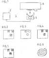
1 eine Blockdarstellung einer Vorrichtung zur Vorbereitung einer induktiven Energieübertragung von einer Ladestation an ein Fahrzeug,2 eine Skizze zur Veranschaulichung eines ersten Ausführungsbeispiels für eine Kennung,3 eine Skizze zur Veranschaulichung eines zweiten Ausführungsbeispiels für eine Kennung,4 eine Skizze zur Veranschaulichung eines dritten Ausführungsbeispiels für eine Kennung,5 eine Skizze zur Veranschaulichung eines vierten Ausführungsbeispiels für eine Kennung und6 eine Skizze zur Veranschaulichung eines weiteren Ausführungsbeispiels.
1 a block diagram of a device for preparing an inductive energy transfer from a charging station to a vehicle,2 a sketch to illustrate a first embodiment of an identifier,3 a sketch illustrating a second embodiment of an identifier,4 a sketch to illustrate a third embodiment of an identifier,5 a sketch illustrating a fourth embodiment of an identifier and6 a sketch to illustrate a further embodiment.
Die
Die dargestellte Vorrichtung weist eine Ladestation
Des Weiteren weist die in der
Die Kennung
Mittels der in der Bodenplatte
Da die in die Fahrzeugplatte
Des Weiteren ermöglicht das als Kennung aufgebrachte geometrische Muster, dass das von der Ladestation
Beispielsweise umfasst diese Signaldiagnose eine Ermittlung der Leistung des reflektierten Signals. Des Weiteren kann mittels der Signaldiagnose eine Bestimmung der Position des Fahrzeugs
Die in die Fahrzeugplatte
Die
Die
Die
Die
Das die Kennung bildende geometrische Muster kann auch sowohl vertikale als auch horizontale Gitterstrukturen aufweisen. Es kann zusätzlich zu den Gitterstrukturen auch weitere geometrische Muster enthalten, die die gewünschte Auswertung des reflektierten Signals erleichtern.The geometric pattern forming the identifier can also have both vertical and horizontal lattice structures. In addition to the lattice structures, it can also contain further geometric patterns that facilitate the desired evaluation of the reflected signal.
Eine zumindest teilweise gitterförmige Ausgestaltung des geometrischen Musters erleichtert eine Positionsbestimmung des Fahrzeugs
Gemäß einer vorteilhaften Weiterbildung der Erfindung werden von der Spule
Die Bautiefe und die Abmessungen der eingebrachten geometrischen Muster sind abhängig von der verwendeten Frequenz des jeweiligen Systems, der verfügbaren Bandbreite und von der Anzahl der jeweils vorhandenen Teilsysteme.The depth and the dimensions of the introduced geometric patterns depend on the frequency of the respective system used, the available bandwidth and the number of existing subsystems.
Eine weitere Alternative besteht darin, das jeweilige geometrische Muster in einer Punkt-Matrix-Form in die Fahrzeugplatte
Ein weiteres Ausführungsbeispiel ist in der
Ein weiteres nicht in den Figuren dargestelltes Ausführungsbeispiel besteht darin, ein von der Spule der Bodenplatte ausgestrahltes elektromagnetisches Signal auf der Fahrzeugseite mittels eines Sensors zu empfangen, dem empfangenen Signal einen Code aufzumodulieren und dann das Signal wieder zur Bodenplatte
Eine ebenfalls nicht in den Figuren dargestellte alternative oder zusätzliche Möglichkeit besteht in einem Invertieren der oben beschriebenen Vorgehensweisen. Dabei wird das oben beschriebene geometrische Muster in die Bodenplatte
Eine weitere Möglichkeit besteht darin, eine bidirektionale Möglichkeit zum Laden und Entladen vorzusehen. Dadurch besteht auch die Möglichkeit, Energie aus dem Fahrzeug zur Bodenstation zu übertragen.Another possibility is to provide a bidirectional option for loading and unloading. This also makes it possible to transfer energy from the vehicle to the ground station.
ZITATE ENTHALTEN IN DER BESCHREIBUNG QUOTES INCLUDE IN THE DESCRIPTION
Diese Liste der vom Anmelder aufgeführten Dokumente wurde automatisiert erzeugt und ist ausschließlich zur besseren Information des Lesers aufgenommen. Die Liste ist nicht Bestandteil der deutschen Patent- bzw. Gebrauchsmusteranmeldung. Das DPMA übernimmt keinerlei Haftung für etwaige Fehler oder Auslassungen.This list of the documents listed by the applicant has been generated automatically and is included solely for the better information of the reader. The list is not part of the German patent or utility model application. The DPMA assumes no liability for any errors or omissions.
Zitierte PatentliteraturPatent literature cited
- US 2016/0178740 A1 [0004]US 2016/0178740 A1 [0004]
Claims (15)
Translated fromGermanPriority Applications (1)
| Application Number | Priority Date | Filing Date | Title |
|---|---|---|---|
| DE102018217080.0ADE102018217080A1 (en) | 2018-10-05 | 2018-10-05 | Method and device for preparing an inductive energy transfer from a charging station to a vehicle |
Applications Claiming Priority (1)
| Application Number | Priority Date | Filing Date | Title |
|---|---|---|---|
| DE102018217080.0ADE102018217080A1 (en) | 2018-10-05 | 2018-10-05 | Method and device for preparing an inductive energy transfer from a charging station to a vehicle |
Publications (1)
| Publication Number | Publication Date |
|---|---|
| DE102018217080A1true DE102018217080A1 (en) | 2019-12-12 |
Family
ID=68651721
Family Applications (1)
| Application Number | Title | Priority Date | Filing Date |
|---|---|---|---|
| DE102018217080.0ACeasedDE102018217080A1 (en) | 2018-10-05 | 2018-10-05 | Method and device for preparing an inductive energy transfer from a charging station to a vehicle |
Country Status (1)
| Country | Link |
|---|---|
| DE (1) | DE102018217080A1 (en) |
Cited By (1)
| Publication number | Priority date | Publication date | Assignee | Title |
|---|---|---|---|---|
| WO2025082657A1 (en)* | 2023-10-18 | 2025-04-24 | Mahle International Gmbh | Method and device for checking the conformity of a positioning device for inductive charging systems |
Citations (5)
| Publication number | Priority date | Publication date | Assignee | Title |
|---|---|---|---|---|
| DE102014000747A1 (en)* | 2014-01-21 | 2015-07-23 | Audi Ag | A system and method for monitoring a gap between a charging plate of a stationary induction charging device and a loading plate of a parked vehicle |
| US20160178740A1 (en) | 2014-12-19 | 2016-06-23 | Qualcomm Incorporated | Systems, methods, and apparatus for living object protection having extended functionality in wireless power transfer applications |
| WO2016193259A1 (en)* | 2015-06-03 | 2016-12-08 | Volkswagen Aktiengesellschaft | Method for determining the position of a motor vehicle relative to a primary coil, motor vehicle, and charging plate |
| DE102015223986A1 (en)* | 2015-12-02 | 2017-06-08 | Robert Bosch Gmbh | Method for operating a radar sensor |
| US20170225582A1 (en)* | 2014-10-29 | 2017-08-10 | Bayerische Motoren Werke Aktiengesellschaft | Method and Base Unit for Inductively Charging Electric and Hybrid Vehicles |
- 2018
- 2018-10-05DEDE102018217080.0Apatent/DE102018217080A1/ennot_activeCeased
Patent Citations (5)
| Publication number | Priority date | Publication date | Assignee | Title |
|---|---|---|---|---|
| DE102014000747A1 (en)* | 2014-01-21 | 2015-07-23 | Audi Ag | A system and method for monitoring a gap between a charging plate of a stationary induction charging device and a loading plate of a parked vehicle |
| US20170225582A1 (en)* | 2014-10-29 | 2017-08-10 | Bayerische Motoren Werke Aktiengesellschaft | Method and Base Unit for Inductively Charging Electric and Hybrid Vehicles |
| US20160178740A1 (en) | 2014-12-19 | 2016-06-23 | Qualcomm Incorporated | Systems, methods, and apparatus for living object protection having extended functionality in wireless power transfer applications |
| WO2016193259A1 (en)* | 2015-06-03 | 2016-12-08 | Volkswagen Aktiengesellschaft | Method for determining the position of a motor vehicle relative to a primary coil, motor vehicle, and charging plate |
| DE102015223986A1 (en)* | 2015-12-02 | 2017-06-08 | Robert Bosch Gmbh | Method for operating a radar sensor |
Cited By (1)
| Publication number | Priority date | Publication date | Assignee | Title |
|---|---|---|---|---|
| WO2025082657A1 (en)* | 2023-10-18 | 2025-04-24 | Mahle International Gmbh | Method and device for checking the conformity of a positioning device for inductive charging systems |
Similar Documents
| Publication | Publication Date | Title |
|---|---|---|
| EP3573866B1 (en) | Method for verifying a predefined maximum spatial distance of a radio key in relation to a motor vehicle, as well as control device, motor vehicle and radio key | |
| DE102018220857A1 (en) | System and procedure for Passive Keyless Entry triggered by smartphone proximity alert | |
| DE112019001523T5 (en) | ULTRA-BROADBAND-BASED VEHICLE ACCESS SYSTEM AND COMMUNICATION PROTOCOL FOR LOCATING A TARGET DEVICE | |
| DE102015218410A1 (en) | Method and device for determining the absolute position of a vehicle | |
| DE102012214199A1 (en) | Device and method for positioning by triangulation | |
| DE102012214201A1 (en) | Positioning with radio-based locking system | |
| WO2016062553A1 (en) | Establishing a charging communication between charging station and vehicle | |
| DE102014213195A1 (en) | Device and method for operating an inductive charging system | |
| DE102015111259A1 (en) | Ultrasonic and infrared object detection for wireless charging of electric vehicles | |
| DE102018102405A1 (en) | Communication system of a vehicle | |
| DE112017001387B4 (en) | SYSTEM FOR COMMUNICATION BETWEEN MOBILE BODIES, CONTROL DEVICE FOR TRANSMISSION IN THE MOBILE BODY AND CONTROL DEVICE FOR RECEPTION IN THE MOBILE BODY | |
| EP3472809A1 (en) | Method for controlling access to a motor vehicle | |
| DE102015226150B4 (en) | Radio device for a vehicle locking system and method for calibrating such a radio device | |
| DE102013217713A1 (en) | Inductive power transmission coil, charging station, method of positioning an inductive power transmission device, and method of detecting a foreign object between a transmission coil and a reception coil | |
| EP2838753B1 (en) | Electric vehicle, inductive charging station, and method | |
| DE102013212060A1 (en) | Vehicle remote control system and method | |
| WO2019030334A1 (en) | MOBILE IDENTIFIER | |
| DE102018208166B4 (en) | Seat recognition system, vehicle, method for vehicle seat recognition, computer program and storage medium | |
| DE102018106063A1 (en) | Sensor arrangement for a contactless charging system | |
| DE102018125379A1 (en) | Device for determining the position of an object movable relative to a vehicle and a vehicle equipped therewith | |
| DE102021102007A1 (en) | LOCATION SYSTEMS AND METHODS FOR WIRELESS SEAT BELT MONITORING IN VEHICLES WITH REMOVABLE OR RECONFIGURABLE SEATS | |
| DE102018217080A1 (en) | Method and device for preparing an inductive energy transfer from a charging station to a vehicle | |
| DE102018207658A1 (en) | A method for processing sensor data, arrangement for processing sensor data, arrangement for processing a request of an ego vehicle for another vehicle, computer for processing sensor data and computer for processing a request of an ego vehicle for another vehicle | |
| DE102017000077B3 (en) | Electronic coupling system | |
| DE102017114223A1 (en) | Near field radar, land, air or water vehicle, use of a radar device, method for operating a radar device and computer program |
Legal Events
| Date | Code | Title | Description |
|---|---|---|---|
| R012 | Request for examination validly filed | ||
| R016 | Response to examination communication | ||
| R230 | Request for early publication | ||
| R002 | Refusal decision in examination/registration proceedings | ||
| R003 | Refusal decision now final |