DE102018214637A1 - Method for determining a direction of view of an eye - Google Patents
Method for determining a direction of view of an eyeDownload PDFInfo
- Publication number
- DE102018214637A1 DE102018214637A1DE102018214637.3ADE102018214637ADE102018214637A1DE 102018214637 A1DE102018214637 A1DE 102018214637A1DE 102018214637 ADE102018214637 ADE 102018214637ADE 102018214637 A1DE102018214637 A1DE 102018214637A1
- Authority
- DE
- Germany
- Prior art keywords
- eye
- laser beam
- laser
- scan
- deflection element
- Prior art date
- Legal status (The legal status is an assumption and is not a legal conclusion. Google has not performed a legal analysis and makes no representation as to the accuracy of the status listed.)
- Withdrawn
Links
Images


Classifications
- G—PHYSICS
- G06—COMPUTING OR CALCULATING; COUNTING
- G06F—ELECTRIC DIGITAL DATA PROCESSING
- G06F3/00—Input arrangements for transferring data to be processed into a form capable of being handled by the computer; Output arrangements for transferring data from processing unit to output unit, e.g. interface arrangements
- G06F3/01—Input arrangements or combined input and output arrangements for interaction between user and computer
- G06F3/011—Arrangements for interaction with the human body, e.g. for user immersion in virtual reality
- G06F3/013—Eye tracking input arrangements
- G—PHYSICS
- G02—OPTICS
- G02B—OPTICAL ELEMENTS, SYSTEMS OR APPARATUS
- G02B27/00—Optical systems or apparatus not provided for by any of the groups G02B1/00 - G02B26/00, G02B30/00
- G02B27/0093—Optical systems or apparatus not provided for by any of the groups G02B1/00 - G02B26/00, G02B30/00 with means for monitoring data relating to the user, e.g. head-tracking, eye-tracking
- A—HUMAN NECESSITIES
- A61—MEDICAL OR VETERINARY SCIENCE; HYGIENE
- A61B—DIAGNOSIS; SURGERY; IDENTIFICATION
- A61B3/00—Apparatus for testing the eyes; Instruments for examining the eyes
- A61B3/10—Objective types, i.e. instruments for examining the eyes independent of the patients' perceptions or reactions
- A61B3/113—Objective types, i.e. instruments for examining the eyes independent of the patients' perceptions or reactions for determining or recording eye movement
- G—PHYSICS
- G02—OPTICS
- G02B—OPTICAL ELEMENTS, SYSTEMS OR APPARATUS
- G02B27/00—Optical systems or apparatus not provided for by any of the groups G02B1/00 - G02B26/00, G02B30/00
- G02B27/01—Head-up displays
- G02B27/017—Head mounted
- G02B27/0172—Head mounted characterised by optical features
- G—PHYSICS
- G02—OPTICS
- G02B—OPTICAL ELEMENTS, SYSTEMS OR APPARATUS
- G02B5/00—Optical elements other than lenses
- G02B5/32—Holograms used as optical elements
- G—PHYSICS
- G01—MEASURING; TESTING
- G01B—MEASURING LENGTH, THICKNESS OR SIMILAR LINEAR DIMENSIONS; MEASURING ANGLES; MEASURING AREAS; MEASURING IRREGULARITIES OF SURFACES OR CONTOURS
- G01B2290/00—Aspects of interferometers not specifically covered by any group under G01B9/02
- G01B2290/65—Spatial scanning object beam
- G—PHYSICS
- G01—MEASURING; TESTING
- G01B—MEASURING LENGTH, THICKNESS OR SIMILAR LINEAR DIMENSIONS; MEASURING ANGLES; MEASURING AREAS; MEASURING IRREGULARITIES OF SURFACES OR CONTOURS
- G01B9/00—Measuring instruments characterised by the use of optical techniques
- G01B9/02—Interferometers
- G01B9/02092—Self-mixing interferometers, i.e. feedback of light from object into laser cavity
- G—PHYSICS
- G01—MEASURING; TESTING
- G01S—RADIO DIRECTION-FINDING; RADIO NAVIGATION; DETERMINING DISTANCE OR VELOCITY BY USE OF RADIO WAVES; LOCATING OR PRESENCE-DETECTING BY USE OF THE REFLECTION OR RERADIATION OF RADIO WAVES; ANALOGOUS ARRANGEMENTS USING OTHER WAVES
- G01S7/00—Details of systems according to groups G01S13/00, G01S15/00, G01S17/00
- G01S7/48—Details of systems according to groups G01S13/00, G01S15/00, G01S17/00 of systems according to group G01S17/00
- G01S7/491—Details of non-pulse systems
- G01S7/4912—Receivers
- G01S7/4916—Receivers using self-mixing in the laser cavity
- G—PHYSICS
- G01—MEASURING; TESTING
- G01S—RADIO DIRECTION-FINDING; RADIO NAVIGATION; DETERMINING DISTANCE OR VELOCITY BY USE OF RADIO WAVES; LOCATING OR PRESENCE-DETECTING BY USE OF THE REFLECTION OR RERADIATION OF RADIO WAVES; ANALOGOUS ARRANGEMENTS USING OTHER WAVES
- G01S7/00—Details of systems according to groups G01S13/00, G01S15/00, G01S17/00
- G01S7/48—Details of systems according to groups G01S13/00, G01S15/00, G01S17/00 of systems according to group G01S17/00
- G01S7/491—Details of non-pulse systems
- G01S7/4912—Receivers
- G01S7/4917—Receivers superposing optical signals in a photodetector, e.g. optical heterodyne detection
- G—PHYSICS
- G02—OPTICS
- G02B—OPTICAL ELEMENTS, SYSTEMS OR APPARATUS
- G02B27/00—Optical systems or apparatus not provided for by any of the groups G02B1/00 - G02B26/00, G02B30/00
- G02B27/01—Head-up displays
- G02B27/017—Head mounted
- G02B2027/0178—Eyeglass type
Landscapes
- Physics & Mathematics (AREA)
- Engineering & Computer Science (AREA)
- General Physics & Mathematics (AREA)
- Optics & Photonics (AREA)
- General Engineering & Computer Science (AREA)
- Theoretical Computer Science (AREA)
- Health & Medical Sciences (AREA)
- Life Sciences & Earth Sciences (AREA)
- Human Computer Interaction (AREA)
- Ophthalmology & Optometry (AREA)
- Biophysics (AREA)
- Biomedical Technology (AREA)
- Heart & Thoracic Surgery (AREA)
- Medical Informatics (AREA)
- Molecular Biology (AREA)
- Surgery (AREA)
- Animal Behavior & Ethology (AREA)
- General Health & Medical Sciences (AREA)
- Public Health (AREA)
- Veterinary Medicine (AREA)
- Length Measuring Devices By Optical Means (AREA)
Abstract
Translated fromGermanDescription
Translated fromGermanDie vorliegende Erfindung betrifft ein Verfahren zum Ermitteln einer Blickrichtung eines Auges, eine Projektionsvorrichtung für eine Datenbrille, eine Datenbrille, ein Computerprogramm, ein maschinenlesbares Speichermedium sowie ein elektronisches Steuergerät.The present invention relates to a method for determining a direction of view of an eye, a projection device for data glasses, data glasses, a computer program, a machine-readable storage medium and an electronic control device.
Stand der TechnikState of the art
Aufgabe der Okulografie, Blickerfassung oder auch engl. eye-tracking ist es, die Bewegung der Augen zu erfassen und die Blickrichtung zu ermitteln. Die Technologie findet breite Anwendung in der Konsumentenforschung, z.B. bei der Beobachtung des Leseflusses zur Optimierung der Platzierung von Werbung.Abandonment of oculography, gaze capture or English. Eye tracking is to record the movement of the eyes and determine the direction of the gaze. The technology is widely used in consumer research, e.g. while observing the reading flow to optimize the placement of advertising.
Bei Datenbrillen, wie z.B. bei Helmet-Mounted- bzw. Head-Mounted- (HMD) oder Head-Worn-Displays (HWD), kommt die Technik auch zum Einsatz, um abhängig von der Blickrichtung des Benutzers den dargestellten Bildinhalt anzupassen. Einerseits kann beispielsweise zur elektrischen Leistungsreduktion die Darstellung hochaufgelöster Bildinhalte auf den Bereich des schärfsten Sehens begrenzt und peripher geringer aufgelöste Inhalte dargestellt werden. Andererseits können vor allem bei Augmented Reality Systemen, welche teil- oder volltransparente Systeme sind, die eine natürliche Wahrnehmung des Umfelds mit der Darstellung virtueller Inhalte kombinieren, Informationen, Ergänzungen und Hinweise aus Gründen der Übersichtlichkeit nur für betrachtete Objekte eingeblendet werden.With data glasses, such as In the case of helmet-mounted or head-mounted (HMD) or head-worn displays (HWD), the technology is also used to adapt the displayed content depending on the viewing direction of the user. On the one hand, for example, for electrical power reduction, the display of high-resolution image content can be limited to the area of the sharpest vision and contents with lower peripheral resolution can be displayed. On the other hand, especially in the case of augmented reality systems, which are partially or fully transparent systems that combine a natural perception of the environment with the display of virtual content, information, additions and information can only be shown for the objects viewed for reasons of clarity.
Technologisch können die verfügbaren Systeme in folgende Kategorien eingeteilt werden:
- Kamerabasierte Systeme: Eine Kamera ist vom Brillengestell auf das Auge gerichtet. Bei einigen Systemen kommen zusätzlich ein oder mehrere Infrarot-Lichtquellen hinzu, die gegebenenfalls moduliert betrieben werden. Durch ein Augenmodell, kontrastbasierte Detektion der Pupille (dark vs. bright pupil), Limbus-Tracking (Kontrastgrenze zwischen Cornea und Sclera) oder Lokalisierung des Hornhautreflexes wird die Blickrichtung aus den Bilddaten ermittelt. Es sind auch Systeme beschrieben worden, die über strukturiertes Licht ein Muster (meist Punktwolken- oder Linienmuster) auf das Auge projizieren und über die charakteristische Formänderung im Bereich der Cornea gegenüber dem Bereich der Sclera die Blickrichtung ermitteln.
- Camera-based systems: A camera is directed from the glasses frame to the eye. In some systems, one or more infrared light sources are added, which may be operated in a modulated manner. The eye direction is determined from the image data using an eye model, contrast-based detection of the pupil (dark vs. bright pupil), limbus tracking (contrast limit between cornea and sclera) or localization of the corneal reflex. Systems have also been described which project a pattern (usually point cloud or line pattern) onto the eye using structured light and determine the direction of view via the characteristic shape change in the area of the cornea compared to the area of the sclera.
Gescannte Lasersysteme: Eine im Brillengestell integrierte Laserquelle wird beispielsweise durch einen Mikro-Elektro- Mechanischen (MEMS) Mikrospiegel über das Auge geführt. Es sind Verfahren bekannt, die basierend auf dem Hornhautreflex die Blickrichtung ermitteln.Scanned laser systems: For example, a laser source integrated in the eyeglass frame is guided over the eye by a micro-electro-mechanical (MEMS) micromirror. Methods are known which determine the viewing direction based on the corneal reflex.
Elektrische Messung: Die durch lonenverschiebungen bei Muskelkontraktion entstehenden messbaren elektrischen Felder können als sogenanntes Elektromyogramm aufgezeichnet werden. Kommt das Verfahren im Bereich der Augen zum Einsatz, spricht man von Elektro-Oculogramm. Durch Signalverarbeitung der abgeleiteten elektrischen Signale kann ebenfalls auf die Augenbewegung geschlossen werdenElectrical measurement: The measurable electric fields resulting from ion shifts during muscle contraction can be recorded as a so-called electromyogram. If the procedure is used in the area of the eyes, one speaks of an electro-oculogram. The eye movement can also be inferred from signal processing of the derived electrical signals
Elektro-Magnetische Messung: Befindet sich eine Spule im Magnetfeld einer anderen Spule, ist die magnetische Kopplung der beiden Spulen von der Ausrichtung zueinander abhängig. Wird eine Spule im Brillengestell und eine weitere Spule in einer Kontaktlinse integriert, ist ebenfalls eine Ermittlung der Blickrichtung möglich.Electro-magnetic measurement: If a coil is in the magnetic field of another coil, the magnetic coupling of the two coils depends on the orientation to one another. If a coil is integrated in the eyeglass frame and another coil is integrated in a contact lens, it is also possible to determine the viewing direction.
Offenbarung der ErfindungDisclosure of the invention
Das Verfahren dient dem Ermitteln einer Blickrichtung eines Auges. Hierbei handelt es sich insbesondere um ein Auge eines Nutzers einer Datenbrille.The method is used to determine a direction of view of an eye. This is in particular an eye of a user of data glasses.
Unter einer Datenbrille kann ein HMD verstanden werden. Unter dem Begriff Datenbrille soll ebenfalls eine Videobrille, ein Helmdisplay oder ein VR-Helm verstanden werden.Data glasses can be understood as an HMD. The term data glasses should also be understood to mean video glasses, a helmet display or a VR helmet.
Die Blickrichtung des Nutzers ist hierbei gegeben durch einen Aufpunkt, welcher z.B. die Mitte der Pupille sein kann, und einen Richtungsvektor, entlang welchem das Auge sieht, welcher z.B. gegeben sein kann durch einen Vektor durch die Mitte der Pupille und einem Punkt auf der Retina, z.B. dem gelben Fleck. Der Aufpunkt kann sich z.B. durch Verschiebungen der Brille relativ zum Auge verändern.The user's line of sight is given by a point, which e.g. can be the center of the pupil and a direction vector along which the eye sees, e.g. can be given by a vector through the center of the pupil and a point on the retina, e.g. the yellow spot. The starting point can e.g. by shifting the glasses relative to the eye.
Bei dem Verfahren wird ein von einer Laserquelle emittierter Laserstrahl über ein Reflexionselement und ein Umlenkelement über mindestens zwei Scanpunkte auf dem Auge, d.h. der Oberfläche des Auges, gescannt.In the method, a laser beam emitted by a laser source is scanned on the eye via a reflection element and a deflection element via at least two scan points, i.e. the surface of the eye, scanned.
Das Reflexionselement dient dem Reflektieren des Lichtstrahls auf das Umlenkelement. Unter einem Reflexionselement kann beispielsweise ein Spiegel, insbesondere ein Mikrospiegel oder ein Array aus Mikrospiegeln, oder ein Hologramm verstanden werden. Mittels des Reflexionselements kann ein Strahlengang des Lichtstrahls an gegebene Raumverhältnisse angepasst werden. Beispielsweise kann das Reflexionselement als Mikrospiegel realisiert sein. Der Mikrospiegel kann beweglich ausgeformt sein, etwa eine um zumindest eine Achse neigbare Spiegelfläche aufweisen. Ein solches Reflexionselement bietet den Vorteil einer besonders kompakten Bauform. Es ist ferner vorteilhaft, wenn das Reflexionselement ausgebildet ist, um einen Einfallswinkel und, zusätzlich oder alternativ, einen Auftreffpunkt des Lichtstrahls auf dem Umlenkelement zu ändern. Dadurch kann das Umlenkelement flächig, insbesondere etwa in Zeilen und Spalten, mit dem Lichtstrahl überstrichen werden.The reflection element serves to reflect the light beam onto the deflection element. A reflection element can be understood to mean, for example, a mirror, in particular a micromirror or an array of micromirrors, or a hologram. A beam path of the light beam can be adapted to given spatial conditions by means of the reflection element. For example, the reflection element can be implemented as a micromirror. The micromirror can be designed to be movable, for example have a mirror surface that can be tilted about at least one axis. Such one Reflection element offers the advantage of a particularly compact design. It is also advantageous if the reflection element is designed to change an angle of incidence and, additionally or alternatively, a point of incidence of the light beam on the deflection element. As a result, the deflecting element can be swept across the surface, in particular approximately in rows and columns, with the light beam.
Das Umlenkelement kann ein holografisches Element oder ein Freiformspiegel sein.The deflection element can be a holographic element or a free-form mirror.
Unter einem holografischen Element kann beispielsweise ein holografischoptisches Bauelement, kurz HOE, verstanden werden, das beispielsweise die Funktion einer Linse, eines Spiegels oder eines Prismas erfüllen kann. Je nach Ausführungsform kann das holografische Element für bestimmte Wellenlängen (Lichtfarben) und Einfallswinkel selektiv sein.A holographic element can be understood to mean, for example, a holographic-optical component, or HOE for short, which can, for example, fulfill the function of a lens, a mirror or a prism. Depending on the embodiment, the holographic element can be selective for certain wavelengths (light colors) and angles of incidence.
Verfügbare photoempfindliche Materialien (z.B. Photopolymerfilme) zur Erzeugung von holografischen Elementen sind nur im sichtbaren Wellenlängenbereich belichtbar. Von großem Vorteil wäre aber für das Verfahren der Einsatz von holografischen Elementen im Nahen Infrarotbereich, damit das Messverfahren für den Nutzer nicht sichtbar ist und um z.B. die Informationsdarstellung einer Datenbrille dadurch nicht zu stören. Durch geeignete Maßnahmen, wie z.B. Winkelvorhalt und/oder optische Immersionsaufbauten kann das photoempfindliche Material mit einer geeigneten Funktion im sichtbaren Wellenlängenbereich so belichtetet werden, dass das holografische Element bei Verwendung im Nahen Infrarot die gewünschte optische Zielfunktion besitzt.Available photosensitive materials (e.g. photopolymer films) for the production of holographic elements can only be exposed in the visible wavelength range. However, it would be of great advantage for the method to use holographic elements in the near infrared range, so that the measuring method is not visible to the user and to e.g. not to disturb the information display of data glasses. By means of suitable measures, e.g. Angular lead and / or optical immersion structures, the photosensitive material can be exposed with a suitable function in the visible wavelength range so that the holographic element has the desired optical target function when used in the near infrared.
Holografische Elemente können insbesondere durch optische Kopierprozesse in großer Stückzahl gefertigt werden. Erfüllt das holografische Element optische Funktionen, die mit einfachen Punkt- oder kollimierten Lichtquellen in das photoempfindliche Material belichtet werden können, gestaltet sich der Kopierprozess (Fertigungsprozess) wesentlich einfacher. Dadurch kann das holografische Element sehr kostengünstig hergestellt werden.Holographic elements can be produced in large numbers, in particular by optical copying processes. If the holographic element fulfills optical functions that can be exposed in the photosensitive material with simple point or collimated light sources, the copying process (manufacturing process) is much simpler. As a result, the holographic element can be produced very inexpensively.
Das holografische Element kann transparent sein. Dadurch können Bildinformationen am Brillenglas mit der Umwelt überlagert werden.The holographic element can be transparent. This allows image information on the lens to be overlaid with the environment.
Bei dem Verfahren wird ein von einer Laserquelle emittierter Laserstrahl über ein Reflexionselement und ein Umlenkelement über mindestens zwei Scanpunkte auf dem Auge gescannt.In the method, a laser beam emitted by a laser source is scanned on the eye via a reflection element and a deflection element via at least two scan points.
Bevorzugt wird der Laserstrahl über eine Vielzahl von Scanpunkten gescannt. Hierbei sind die Scanpunkte auf der Oberfläche des Auges so verteilt, dass die die Blickrichtung des Auges ermittelt werden kann. Dies ist bevorzugt dann der Fall, wenn die Scanpunkte auf der Oberfläche des Auges zumindest einen Teil der Pupille abdecken. Es ist weiter bevorzugt, wenn die Scanpunkte auf der Oberfläche des Auges das ganze Auge überdecken. Hierbei wird unter den Wörtern „Abdecken“ oder „Überdecken“ nicht verstanden, dass jeder einzelne Punkt abgescannt werden muss. Es reicht, wenn die Einhüllende der abgescannten Punkte größer ist als der Teil des Auges oder das ganze Auge.The laser beam is preferably scanned over a multiplicity of scan points. Here, the scan points are distributed on the surface of the eye so that the direction of the eye can be determined. This is preferably the case when the scan points on the surface of the eye cover at least part of the pupil. It is further preferred if the scan points on the surface of the eye cover the entire eye. The words “covering” or “covering” are not understood to mean that each individual point must be scanned. It is sufficient if the envelope of the scanned points is larger than the part of the eye or the whole eye.
Bei dem Verfahren wird ein Self-mixing-Effekt des vom Auge in die Laserquelle zurückgeworfenen gescannten Laserstrahls genutzt, um für die mindestens zwei Scanpunkte die optische Weglänge von der Laserquelle bis zu den mindestens zwei Scanpunkten auf der Augenoberfläche und/oder eine Reflektivität des Auges an den mindestens zwei Scanpunkten zu bestimmen.In the method, a self-mixing effect of the scanned laser beam thrown back by the eye into the laser source is used to determine the optical path length from the laser source to the at least two scan points on the surface of the eye and / or a reflectivity of the eye for the at least two scan points to determine the at least two scan points.
Bei dem Self-mixing-Effekt, auch „Laser Self Mixing“ genannt, wird die von einem Laser ausgesandte kohärente Strahlung von einer Oberfläche gestreut und ein Teil dieser Strahlung gelangt wieder zurück in die Laserkavität, den optischen Resonator. Falls die zweifache Entfernung zum Streuer einem ganzzahligen Vielfachen der Wellenlänge entspricht, so befindet sich die zurückgestreute Strahlung in Phase mit der Strahlung in der Laserkavität. Damit addiert sie sich konstruktiv zu der dort befindlichen Strahlung, reduziert die Laserschwelle und steigert damit die Ausgangsleistung des Lasers. Wird nun die Entfernung des Streuers und damit die zurückgelegte optische Weglänge geändert, kommt es immer wieder in Abhängigkeit der Entfernung zu positiver oder negativer Interferenz innerhalb der Laserkavität, sodass die Leistung des Lasers in einem sinusförmigen Muster zwischen einem Strahlungsmaximum und einem Strahlungsminimum moduliert wird. Ähnliche Intensitätsmodulationen werden erreicht, wenn die Wellenlänge des Lasers moduliert wird oder wenn sich die Frequenz des rückgestreuten Laserlichts verändert, z.B. durch den Dopplereffekt, welcher bei der Reflektion an bewegten Objekten auftritt. Wird nun die optische Strahlungsleistung durch eine Photodiode (engl.: monitoring photo diode) gemessen, kann anhand der Amplitudenänderung der Strahlungsleistung auf die Intensitätsänderung der zurückgestreuten Laserleistung geschlossen werden. Über eine Analyse der Anzahl der Schwingungen, z.B. durch Zählen der Nulldurchgänge oder der Maximalwerte, kann auch auf die Anzahl der Schwingungen, also Durchlaufvorgänge konstruktiver und destruktiver Interferenz, und damit bei bekannter Laser-Wellenlänge und Modulation auf die Entfernung und eventuelle Entfernungsänderungen zwischen Laserkavität und Streuer sowie auf die zum Laserstrahl parallele Geschwindigkeitskomponente des Streuers geschlossen werden. Zusätzlich zu Entfernung und Geschwindigkeit des Streuers kann die absolute Intensität des Rückstreusignals zu einer Berechnung der Reflektivität des Streuers genutzt werden. Dementsprechend weist der Laser bevorzugt eine integrierte Photodiode auf, welche die optische Strahlungsleistung des Lasers misst.In the self-mixing effect, also known as “laser self-mixing”, the coherent radiation emitted by a laser is scattered from a surface and part of this radiation is returned to the laser cavity, the optical resonator. If twice the distance to the scatterer corresponds to an integral multiple of the wavelength, then the backscattered radiation is in phase with the radiation in the laser cavity. It thus adds constructively to the radiation located there, reduces the laser threshold and thus increases the output power of the laser. If the distance of the spreader and thus the optical path length is changed, there is always positive or negative interference within the laser cavity depending on the distance, so that the power of the laser is modulated in a sinusoidal pattern between a radiation maximum and a radiation minimum. Similar intensity modulations are achieved if the wavelength of the laser is modulated or if the frequency of the backscattered laser light changes, for example due to the Doppler effect which occurs when reflecting on moving objects. If the optical radiation power is now measured by a photodiode (monitoring photo diode), the change in intensity of the radiation power can be inferred from the change in intensity of the backscattered laser power. An analysis of the number of vibrations, e.g. by counting the zero crossings or the maximum values, can also be used to determine the number of vibrations, i.e. throughputs of constructive and destructive interference, and thus with known laser wavelength and modulation on the distance and possible distance changes between the laser cavity and Spreader as well as the speed component of the spreader parallel to the laser beam. In addition to the distance and speed of the spreader, the absolute Intensity of the backscatter signal can be used to calculate the reflectivity of the scatterer. Accordingly, the laser preferably has an integrated photodiode, which measures the optical radiation power of the laser.
Gemäß einer bevorzugten Ausführungsform wird aufgrund von unterschiedlichen Reflektivitäten unterschiedlicher Teile des Auges an den mindestens zwei Scanpunkten die Blickrichtung des Auges ermittelt. Diese Ausführungsform wird vorliegend Umsetzungsvariante
Die unterschiedlichen Teile des Auges sind bevorzugt die Sklera, welche auch Lederhaut genannt wird, die Iris, welche auch Regenbogenhaut genannt wird, und die Pupille. Aufgrund der unterschiedlichen Reflektivitäten von Sklera, Iris und Pupille, welche von dem Scan über das Auge erhalten wurden, kann vorteilhafterweise die Blickrichtung des Auges ermittelt werden.The different parts of the eye are preferably the sclera, which is also called the dermis, the iris, which is also called the iris, and the pupil. Due to the different reflectivities of sclera, iris and pupil, which were obtained from the scan via the eye, the direction of the eye can advantageously be determined.
Gemäß einer bevorzugten Ausführungsform wird die Blickrichtung eines Auges durch den „Rote-Augen-Effekt“ ermittelt, indem ein Scanpunkt auf dem Auge gesucht wird, bei dem der Laserstrahl an der Retina des Auges reflektiert wird. Diese Ausführungsform wird vorliegend Umsetzungsvariante
Bei dem bekannten „Rote-Augen-Effekt“ findet eine Reflexion an der Retina statt. Ist die Lichtquelle näherungsweise auf der optischen Achse des Beobachters angeordnet, so sind Ein- und Ausfallswinkel der Strahlung gleich und ein starker Reflex ist beobachtbar. Für alle anderen Winkel erscheint die Pupille dunkel, da Einfalls- und Ausfallswinkel der Strahlung nicht übereinstimmen und die Strahlungsleistung durch Mehrfachreflexionen im Auge geschluckt wird.With the well-known "red-eye effect", there is a reflection on the retina. If the light source is arranged approximately on the optical axis of the observer, the angles of incidence and emission of the radiation are the same and a strong reflection can be observed. The pupil appears dark for all other angles, since the angles of incidence and exit of the radiation do not match and the radiation power is swallowed by multiple reflections in the eye.
Dieses Merkmal ermöglicht vorteilhafterweise eine genaue Bestimmung der Pupillenposition, da sich die Reflektivität der Pupille bzw. der dahinter sichtbaren Retina stark von der Reflektivität anderer Teile des Auges unterscheidet.This feature advantageously enables a precise determination of the pupil position, since the reflectivity of the pupil or the retina visible behind it differs greatly from the reflectivity of other parts of the eye.
Gemäß einer bevorzugten Ausführungsform wird ein Oberflächenprofil des Auges ermittelt, indem mithilfe des Self-mixing-Effekts, welcher während eines Scannens des Laserstrahls über das Auge eine Modulation der Laserleistung bewirkt, eine Änderung einer optischen Weglänge von der Laserquelle zu einem aktuellen Scanpunkt auf der Augenoberfläche ermittelt wird. Diese Ausführungsform wird vorliegend Umsetzungsvariante
Die Modulation der Laserleistung ist eine sinusförmige Funktion der Änderung der optischen Weglänge von der Laserquelle zum aktuellen Scanpunkt auf der Augenoberfläche. Anhand der gemessenen Modulation kann somit die Änderung der optischen Weglänge ermittelt werden.The modulation of the laser power is a sinusoidal function of the change in the optical path length from the laser source to the current scan point on the surface of the eye. The change in the optical path length can thus be determined on the basis of the measured modulation.
Hieraus folgt, dass anhand der bekannten geometrischen Anordnung der Laserquelle, des Reflexionselements und des Umlenkelements sowie anhand der bekannten optischen Eigenschaften des Umlenkelements für jeden Scanpunkt die Entfernung von der Laserquelle zur Oberfläche des Auges ermittelt werden kann. Da die geometrische Anordnung der Laserquelle, des Reflexionselements und des Umlenkelements bekannt sind, kann somit auch das Oberflächenprofil des Auges ermittelt werden, wodurch wiederum die Blickrichtung ermittelt werden kann.It follows from this that the distance from the laser source to the surface of the eye can be determined for each scan point on the basis of the known geometric arrangement of the laser source, the reflection element and the deflection element and on the basis of the known optical properties of the deflection element. Since the geometrical arrangement of the laser source, the reflection element and the deflecting element are known, the surface profile of the eye can thus also be determined, which in turn enables the viewing direction to be determined.
Eine Änderung der optischen Weglänge bewirkt ein Durchlaufen mehrerer Extremstellen in der Laserleistungsmodulation durch eine konstruktive und destruktive Interferenz des Self-mixing-Effekts. Die relative Formänderung kann durch Analyse der Anzahl der durchlaufenen Extrema bestimmt werden.A change in the optical path length causes a passage through several extreme points in the laser power modulation through a constructive and destructive interference of the self-mixing effect. The relative shape change can be determined by analyzing the number of extremes passed.
Da die Wellenlänge der verwendeten Laserstrahlung bevorzugt im nahen Infrarot und damit in der Größenordnung eines Mikrometers liegt, bewirkt eine Änderung des Oberflächenprofils des Auges um z.B. 1 mm ein Durchlaufen von mehr als 2000 Extremstellen. Hieran erkennt man, dass durch diese Technik das Oberflächenprofil des Auges sehr genau vermessen werden kann. Alternativ zum vorstehend genannten Merkmal kann ein Gradient einer Modulation der Laserleistung zur Bestimmung eines Gradienten des Oberflächenprofils des Auges verwendet werden. Alternativ formuliert kann eine Steigung der Abstandsänderung mit einem zeitlichen Abstand der Extrema oder Nulldurchgänge der optischen Laserleistung verknüpft werden. Daher kann auch die Frequenz der zeitlichen Extrema als Maß für die Form und damit für die Blickrichtung herangezogen werden.Since the wavelength of the laser radiation used is preferably in the near infrared and thus on the order of a micron, a change in the surface profile of the eye causes e.g. 1 mm a passage through more than 2000 extreme points. This shows that the surface profile of the eye can be measured very precisely using this technique. As an alternative to the feature mentioned above, a gradient of a modulation of the laser power can be used to determine a gradient of the surface profile of the eye. Alternatively, an increase in the change in distance can be linked to a time interval between the extremes or zero crossings of the optical laser power. Therefore, the frequency of the temporal extremes can also be used as a measure of the shape and thus the direction of the gaze.
Gemäß einer bevorzugten Ausführungsform kann die Ausführungsform, wonach unterschiedliche Reflexivitäten unterschiedlicher Teile des Auges ermittelt werden, und die Ausführungsform, wonach eine Änderung der optischen Weglänge ermittelt wird, miteinander kombiniert werden. Dies hat den Vorteil, dass das Oberflächenprofil des Auges wesentlich genauer bestimmbar ist.According to a preferred embodiment, the embodiment according to which different reflectivities of different parts of the eye are determined and the embodiment according to which a change in the optical path length is determined can be combined with one another. This has the advantage that the surface profile of the eye can be determined much more precisely.
Gemäß einer weiteren bevorzugten Ausführungsform ist das Umlenkelement so angeordnet und eingerichtet, dass der Laserstrahl für jede Scanstellung des Reflexionselements vom Umlenkelement in jeweils dieselbe Richtung umgelenkt wird. Diese Richtung ist bevorzugt parallel zu mindestens einer Blickrichtung des Auges und weiter bevorzugt zu einer Blickrichtung geradeaus nach vorne. Die Blickrichtung geradeaus nach vorne ist dadurch definiert, dass die Blickrichtung im Wesentlichen senkrecht auf der Ebene des Brillenglases steht.According to a further preferred embodiment, the deflection element is arranged and set up in such a way that the laser beam is deflected by the deflection element in each case in the same direction for each scanning position of the reflection element. This direction is preferably parallel to at least one viewing direction of the eye and more preferably to looking straight ahead. The viewing direction straight ahead is defined by the fact that the viewing direction is essentially perpendicular to the plane of the spectacle lens.
Diese Ausführungsform des HOE ist für die Umsetzungsvariante
Hierbei werden die scanwinkelabhängig einfallenden Laserstrahlen in parallel austretende Laserstrahlen umgelenkt. Da die Orientierung des Umlenkelements und des Reflexionselements durch das Brillengestell fest vorgegeben sind, ist somit auch die Austrittsposition des Laserstrahls aus dem Umlenkelement in Richtung des Auges fest. Eine weitere Koordinatensystemtransformation in Abhängigkeit des Abstandes des Auges vom Umlenkelement entfällt somit vorteilhafterweise.Here, the laser beams incident depending on the scanning angle are deflected into laser beams emerging in parallel. Since the orientation of the deflecting element and the reflecting element is fixed by the spectacle frame, the exit position of the laser beam from the deflecting element in the direction of the eye is thus also fixed. A further coordinate system transformation depending on the distance of the eye from the deflecting element is thus advantageously omitted.
Gemäß noch einer weiteren bevorzugten Ausführungsform ist das Umlenkelement so angeordnet und eingerichtet, dass für jede Scanstellung des Reflexionselements eine Augenstellung existiert, deren Blickrichtung parallel zur Ausbreitungsrichtung des vom Umlenkelement in dieser Scanstellung umgelenkten Laserstrahls ist. Bevorzugt sind in diesem Fall die Laserstrahlen vom Umlenkelement kommend konvergent und schneiden sich in einem Punkt im Inneren des Augapfels, bevorzugt im Drehpunkt des Auges.According to yet another preferred embodiment, the deflection element is arranged and set up in such a way that for each scan position of the reflection element there is an eye position, the direction of which is parallel to the direction of propagation of the laser beam deflected by the deflection element in this scan position. In this case, the laser beams coming from the deflection element are preferably convergent and intersect at a point in the interior of the eyeball, preferably at the center of rotation of the eye.
Hierdurch wird vorteilhafterweise erreicht, dass für jeden Blickwinkel des Auges an derjenigen Stelle, an der der Blick das Umlenkelement trifft, ein Laserstrahl existiert, welcher parallel zur Sehachse verläuft. Ferner wird eine Erhöhung der Auflösung durch eine Beschränkung des Winkelbereichs erzielt.It is hereby advantageously achieved that for each viewing angle of the eye, at the point at which the view meets the deflecting element, there is a laser beam which runs parallel to the visual axis. Furthermore, the resolution is increased by restricting the angular range.
Gemäß einer anderen bevorzugten Ausführungsform ist das Umlenkelement so angeordnet und eingerichtet, dass die Laserstrahlen, welche für unterschiedliche Scanstellungen des Reflexionselements vom Umlenkelement umgelenkt werden, divergent sind. Bevorzugt sind hierbei die Strahlen divergent und schneiden sich in einem Punkt, welcher auf einem Punkt der Blickrichtung liegt, bevorzugt auf einer Blickrichtung geradeaus nach vorne.According to another preferred embodiment, the deflection element is arranged and set up in such a way that the laser beams which are deflected by the deflection element for different scanning positions of the reflection element are divergent. In this case, the beams are preferably divergent and intersect at a point which lies at a point in the viewing direction, preferably straight ahead in one viewing direction.
Diese Ausführungsform ist vor allem für die Umsetzungsvarianten
Gemäß einer bevorzugten Ausführungsform ist das Umlenkelement so angeordnet und eingerichtet, dass das Umlenkelement mindestens zwei unterschiedliche Bereiche hat, wobei jeder Bereich des Umlenkelements die auf sie treffenden Laserstrahlen auf jeweils einen Punkt auf dem Auge umlenkt.According to a preferred embodiment, the deflecting element is arranged and set up in such a way that the deflecting element has at least two different areas, each area of the deflecting element deflecting the laser beams striking it to a point on the eye in each case.
Bevorzugt sind die unterschiedlichen Bereiche disjunkt.The different areas are preferably disjoint.
Bevorzugt weist das Umlenkelement eine Vielzahl von Bereichen auf, wobei die von der Vielzahl von Bereichen auf das Auge umgelenkten Punkte gleichmäßig über das Auge verteilt sind. Gemäß einer weiteren bevorzugten Ausführungsform ist ein solcher Bereich eine horizontal verlaufende Zeile oder Scanzeile des bevorzugt auf dem Brillenglas angeordneten Umlenkelements. Noch weiter bevorzugt weist das Umlenkelement eine Vielzahl von horizontal verlaufenden zeilenförmigen Bereichen auf, wobei jeder zeilenförmige Bereich oder mehrere zeilenförmige Bereiche die auf sie fallenden Laserstrahlen jeweils auf einen Punkt auf dem Auge umlenkt. Hierbei gibt es eine Eins-zu-eins-Zuordnung zwischen den horizontalen Bereichen und den Scanpunkten auf dem Auge, wobei jeder Bereich nur einem Punkt zugeordnet und jeder Punkt nur einem Bereich zugeordnet ist.The deflection element preferably has a multiplicity of regions, the points deflected from the multiplicity of regions onto the eye being distributed uniformly over the eye. According to a further preferred embodiment, such a region is a horizontally running line or scan line of the deflection element which is preferably arranged on the spectacle lens. Even more preferably, the deflecting element has a multiplicity of horizontally running line-shaped regions, each line-shaped region or a plurality of line-shaped regions respectively deflecting the laser beams falling on it to a point on the eye. Here there is a one-to-one assignment between the horizontal areas and the scan points on the eye, each area being assigned to only one point and each point being assigned to only one area.
Diese Ausführungsform ist vorteilhaft, falls die Messqualität bei einem schnell scannenden System nicht ausreicht oder anders ausgedrückt, falls pro Messpunkt eine zu geringe Lichtausbeute vorliegt.This embodiment is advantageous if the measurement quality in a fast-scanning system is insufficient or, in other words, if the light efficiency is too low for each measurement point.
Die mindestens zwei unterschiedlichen Bereiche werden analog zu dem Eyebox-Konzept eines HOE definiert, welche ähnlich einem Parabolspiegel die Strahlen auf einen Punkt des Auges, die sogenannte Eyebox, fokussieren. Hierdurch wird vorteilhafterweise erreicht, dass die Auswerteelektronik vor allem bei der Umsetzungsvariante
Bei einem hochaufgelösten Projektionssystem mit beispielsweise 720 Zeilen ergeben sich ausreichend Messpunkte für eine Messung des Blickwinkels bei verhältnismäßig langer Verweilzeit an einem Messpunkt.In a high-resolution projection system with, for example, 720 lines, there are sufficient measuring points for measuring the viewing angle with a relatively long dwell time at a measuring point.
Die Projektionsvorrichtung für eine Datenbrille weist eine Laserquelle zum Aussenden eines Lichtstrahls auf. Ferner weist die Projektionsvorrichtung ein an einem Brillenglas der Datenbrille angeordnetes oder anordenbares Umlenkelement zum Umlenken des Laserstrahls in Richtung eines Auges des Nutzers und/oder zum Fokussieren des Laserstrahls auf. Darüber hinaus weist die Projektionsvorrichtung ein Reflexionselement zum Reflektieren des Laserstrahls auf das Umlenkelement auf.The projection device for data glasses has a laser source for emitting a light beam. Furthermore, the projection device has a deflection element which is arranged or can be arranged on a spectacle lens of the data glasses, for deflecting the laser beam in the direction of an eye of the user and / or for focusing the laser beam. In addition, the projection device has a reflection element for reflecting the laser beam onto the deflection element.
Die Projektionsvorrichtung ist ausgeführt und eingerichtet, ein Verfahren zum Ermitteln einer Blickrichtung eines Auges durchzuführen. Somit kann die Projektionsvorrichtung dieselben Vorteile wie das oben beschriebene Verfahren erzielen. The projection device is designed and set up to carry out a method for determining a direction of view of an eye. Thus, the projection device can achieve the same advantages as the method described above.
Die Datenbrille weist ein Brillenglas und eine oben beschriebene Projektionsvorrichtung auf, wobei das Umlenkelement am Brillenglas angeordnet ist. Die Datenbrille erreicht genauso wie die Projektionsvorrichtung dieselben Vorteile wie das oben beschriebene Verfahren.The data glasses have a spectacle lens and a projection device described above, the deflecting element being arranged on the spectacle lens. Like the projection device, the data glasses achieve the same advantages as the method described above.
Die Erfindung umfasst weiterhin ein Computerprogramm, das zur Durchführung der beschriebenen Schritte des Verfahrens eingerichtet ist, um mit diesem Computerprogramm das oben beschriebene Verfahren durchführen zu können. Weiterhin umfasst die Erfindung ein maschinenlesbares Speichermedium, auf welchem ein solches Computerprogramm gespeichert ist, sowie ein elektronisches Steuergerät, das zur Durchführung der Schritte des beschriebenen Verfahrens eingerichtet ist. Ein solches elektronische Steuergerät kann beispielsweise als Mikrocontroller in eine Projektionsvorrichtung oder Datenbrille integriert sein.The invention further comprises a computer program which is set up to carry out the described steps of the method in order to be able to carry out the method described above with this computer program. Furthermore, the invention comprises a machine-readable storage medium, on which such a computer program is stored, and an electronic control device, which is set up to carry out the steps of the described method. Such an electronic control unit can be integrated, for example, as a microcontroller in a projection device or data glasses.
FigurenlisteFigure list
Ausführungsbeispiele der Erfindung sind in den Zeichnungen dargestellt und werden in der nachfolgenden Beschreibung näher erläutert.
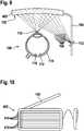
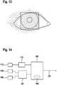
1 zeigt eine schematische Darstellung einer Anordnung einer Datenbrille gemäß einer Ausführungsform und eines Auges eines Nutzers.2 zeigt eine schematische Verteilung von Scanpunkten auf einem abgescannten Auge gemäß einer Ausführungsform des Verfahrens.3 zeigt ein schematisches Ablaufdiagramm eines Verfahrens gemäß einem Ausführungsbeispiel der Erfindung.4 ,5 ,6 ,7 ,8 , und9 zeigen jeweils eine schematische Darstellung einer Anordnung einer Datenbrille gemäß einer Ausführungsform und eines Auges eines Nutzers, wobei sich die physikalischen Eigenschaften des als HOE ausgeführten Umlenkelements unterscheiden.10 zeigt eine Datenbrille mit einem Brillenglas gemäß der Ausführungsform der8 und9 .11 zeigt schematische Messdaten der optischen Weglänge in Abhängigkeit eines horizontalen Scanwinkels gemäß einer Ausführungsform des Verfahrens.12 und13 zeigen schematische Messergebnisse einer Ausführungsform des Verfahrens.14 zeigt ein Blockschaltbild einer Ausführungsform einer P rojektionsvorrichtu ng.
1 shows a schematic representation of an arrangement of data glasses according to an embodiment and an eye of a user.2 shows a schematic distribution of scan points on a scanned eye according to an embodiment of the method.3 shows a schematic flow diagram of a method according to an embodiment of the invention.4 .5 .6 .7 .8th , and9 each show a schematic representation of an arrangement of data glasses in accordance with an embodiment and an eye of a user, the physical properties of the deflection element designed as HOE differing.10 shows a data glasses with a spectacle lens according to the embodiment of8th and9 ,11 shows schematic measurement data of the optical path length depending on a horizontal scanning angle according to an embodiment of the method.12 and13 show schematic measurement results of an embodiment of the method.14 shows a block diagram of an embodiment of a projection device.
Ausführungsbeispiele der ErfindungEmbodiments of the invention
Ein von der Scanneroptik
Die Projektionsvorrichtung
In einer weiteren Ausführungsform kann die Projektionsvorrichtung gleichzeitig ein Verfahren zur Erzeugung eines sichtbaren Bildes auf die Netzhaut und ein Verfahren zur Ermittlung einer Blickrichtung des Auges durchführen. Dabei können die optischen Funktionen des HOEs im Umlenkelement sich für verschiedene Wellenlängen unterscheiden.In a further embodiment, the projection device can simultaneously carry out a method for producing a visible image on the retina and a method for determining a direction of view of the eye. The optical functions of the HOE in the deflection element can differ for different wavelengths.
Beim Scannen des Laserstrahls
Die Bestimmung der Blickrichtung
In dieser Konstellation wird bevorzugt ein Verfahren
Dies ist besonders vorteilhaft für die Umsetzungsvarianten
Dies ist insbesondere dann vorteilhaft, wenn die Messqualität bei einem schnell scannenden System nicht ausreicht. Dadurch kann die Auswerteelektronik vor allem beim Umsetzungsprinzip
Eine weitere Variante dieses Ansatzes ist in
Bei einem hochaufgelösten Projektionssystem mit beispielsweise 720 Zeilen ergeben sich somit ausreichend Scanpunkte
Hierbei können Auswerteverfahren direkt Parameter der Kurvenform wie Wendepunkte, Schnittpunkte und Extremstellen sein, es kann allerdings auch ein sogenanntes „template matching“ zum Einsatz kommen, bei dem eine Modellfunktion an die gemessenen Daten angepasst wird. Eine skizzenhafte Darstellung der Ergebnisse einer Messung entsprechend Umsetzungsprinzip
Da Laser
Falls die Intensitätsscans z.B. zu einem zweidimensionalen Array zusammengesetzt werden, so kann nach einer optionalen Filterung das Maximum bzw. der Mittelpunkt des Reflexionsmaximums bestimmt werden und daraus die Blickrichtung ermittelt werden.If the intensity scans e.g. can be put together to form a two-dimensional array, the maximum or the center of the reflection maximum can be determined after an optional filtering and the viewing direction can be determined therefrom.
Die Filterung kann ein räumlicher Glättungskernel sein, welcher eine Glättung der Signale bewirken, so dass eine Software, welche ein Maximum der Intensitätsverteilung sucht, nicht einen Ausreißer neben dem Hauptmaximum findet.The filtering can be a spatial smoothing kernel, which causes the signals to be smoothed, so that software which seeks a maximum of the intensity distribution does not find an outlier next to the main maximum.
Claims (14)
Translated fromGermanPriority Applications (6)
| Application Number | Priority Date | Filing Date | Title |
|---|---|---|---|
| DE102018214637.3ADE102018214637A1 (en) | 2018-08-29 | 2018-08-29 | Method for determining a direction of view of an eye |
| KR1020217008707AKR20210049868A (en) | 2018-08-29 | 2019-08-12 | Method for detecting the eye's gaze direction |
| CN201980056837.9ACN112639555A (en) | 2018-08-29 | 2019-08-12 | Method for determining the direction of the eye line of sight |
| EP19753334.2AEP3844537B1 (en) | 2018-08-29 | 2019-08-12 | Method for ascertaining a viewing direction of an eye |
| PCT/EP2019/071562WO2020043472A1 (en) | 2018-08-29 | 2019-08-12 | Method for ascertaining a viewing direction of an eye |
| US17/259,157US11868522B2 (en) | 2018-08-29 | 2019-08-12 | Method for ascertaining a viewing direction of an eye |
Applications Claiming Priority (1)
| Application Number | Priority Date | Filing Date | Title |
|---|---|---|---|
| DE102018214637.3ADE102018214637A1 (en) | 2018-08-29 | 2018-08-29 | Method for determining a direction of view of an eye |
Publications (1)
| Publication Number | Publication Date |
|---|---|
| DE102018214637A1true DE102018214637A1 (en) | 2020-03-05 |
Family
ID=67659859
Family Applications (1)
| Application Number | Title | Priority Date | Filing Date |
|---|---|---|---|
| DE102018214637.3AWithdrawnDE102018214637A1 (en) | 2018-08-29 | 2018-08-29 | Method for determining a direction of view of an eye |
Country Status (6)
| Country | Link |
|---|---|
| US (1) | US11868522B2 (en) |
| EP (1) | EP3844537B1 (en) |
| KR (1) | KR20210049868A (en) |
| CN (1) | CN112639555A (en) |
| DE (1) | DE102018214637A1 (en) |
| WO (1) | WO2020043472A1 (en) |
Cited By (19)
| Publication number | Priority date | Publication date | Assignee | Title |
|---|---|---|---|---|
| DE102020206452A1 (en) | 2020-05-25 | 2021-11-25 | Robert Bosch Gesellschaft mit beschränkter Haftung | Projection and oculography device for data glasses and method for operating a projection and oculography device for data glasses |
| DE102020206821A1 (en) | 2020-06-02 | 2021-12-02 | Robert Bosch Gesellschaft mit beschränkter Haftung | Method for determining a line of sight of an eye |
| DE102020206822A1 (en) | 2020-06-02 | 2021-12-02 | Robert Bosch Gesellschaft mit beschränkter Haftung | Procedure for operating data glasses |
| DE102020127594A1 (en) | 2020-10-20 | 2022-04-21 | Robert Bosch Gesellschaft mit beschränkter Haftung | OPTICAL ARRANGEMENT OF DATA GLASSES |
| DE102021110109A1 (en) | 2021-04-21 | 2022-10-27 | Robert Bosch Gesellschaft mit beschränkter Haftung | Method for recognizing eye gestures of an eye |
| EP4083567A1 (en)* | 2021-04-30 | 2022-11-02 | TRUMPF Photonic Components GmbH | Laser sensor, system and method for self-mixing interferometry |
| DE102021210056A1 (en) | 2021-09-13 | 2023-03-16 | Robert Bosch Gesellschaft mit beschränkter Haftung | Motion detection device, smart glasses with the motion detection device, and use of the motion detection device |
| DE102022202000A1 (en) | 2022-02-28 | 2023-08-31 | Robert Bosch Gesellschaft mit beschränkter Haftung | Method and device for determining an eye position using a laser device for data glasses and laser device |
| DE102022203800A1 (en) | 2022-04-14 | 2023-10-19 | Robert Bosch Gesellschaft mit beschränkter Haftung | Optical system for pupil detection of a user of data glasses |
| DE102022203850A1 (en) | 2022-04-20 | 2023-10-26 | Robert Bosch Gesellschaft mit beschränkter Haftung | Device and method for determining a pupil position |
| DE102022207025A1 (en) | 2022-07-11 | 2024-01-11 | Robert Bosch Gesellschaft mit beschränkter Haftung | Method for operating data glasses, computing unit and data glasses comprising a virtual retinal display |
| DE102022208691A1 (en)* | 2022-08-23 | 2024-02-29 | Robert Bosch Gesellschaft mit beschränkter Haftung | Device for monitoring an eye position of a user's eye in a virtual retinal display, data glasses and method |
| DE102022210271A1 (en) | 2022-09-28 | 2024-03-28 | Robert Bosch Gesellschaft mit beschränkter Haftung | Eye tracking device, data glasses and eye tracking method |
| DE102022211250A1 (en) | 2022-10-24 | 2024-04-25 | Robert Bosch Gesellschaft mit beschränkter Haftung | Method for determining at least one eye condition of at least one person arranged in a defined spatial area |
| US11983315B2 (en) | 2021-08-05 | 2024-05-14 | Samsung Electronics Co., Ltd. | Augmented reality device and method for detecting gaze of user |
| DE102023204808A1 (en) | 2023-05-24 | 2024-11-28 | Robert Bosch Gesellschaft mit beschränkter Haftung | Method for determining a surface velocity of an eye of a user of a spectacle device arranged on the head of the user |
| DE102023205844A1 (en) | 2023-06-22 | 2024-12-24 | Robert Bosch Gesellschaft mit beschränkter Haftung | Pupil detection method, pupil detection device and data glasses |
| DE102023206107A1 (en) | 2023-06-28 | 2025-01-02 | Robert Bosch Gesellschaft mit beschränkter Haftung | Optical system for pupil detection of a user of data glasses |
| DE102023206839A1 (en) | 2023-07-19 | 2025-01-23 | Robert Bosch Gesellschaft mit beschränkter Haftung | Device and method for capturing at least one stereo image of a pupil of an eye, hologram unit and data glasses |
Families Citing this family (14)
| Publication number | Priority date | Publication date | Assignee | Title |
|---|---|---|---|---|
| US11860371B1 (en)* | 2019-05-30 | 2024-01-02 | Snap Inc. | Eyewear with eye-tracking reflective element |
| DE102019119913A1 (en)* | 2019-07-23 | 2021-01-28 | Implandata Ophthalmic Products Gmbh | Arrangement and method for capturing a field of view and use of an implant |
| US11719937B2 (en)* | 2020-05-21 | 2023-08-08 | Apple Inc. | Head-mounted electronic device with self-mixing sensors |
| US11836287B1 (en)* | 2020-09-22 | 2023-12-05 | Apple Inc. | Light pattern-based alignment for retinal eye tracking |
| DE102020127593A1 (en)* | 2020-10-20 | 2022-04-21 | Robert Bosch Gesellschaft mit beschränkter Haftung | EYE TRACKING ARRANGEMENT |
| US11536555B2 (en)* | 2021-02-03 | 2022-12-27 | Meta Platforms Technologies, Llc | Scanning self-mixing interferometry system and sensor |
| CN113509138A (en)* | 2021-05-11 | 2021-10-19 | 岭南师范学院 | A pupillary photoreflectometer for autistic children with laser self-mixing interference |
| GB202107238D0 (en)* | 2021-05-20 | 2021-07-07 | Ams Int Ag | Eye movement determination |
| GB202107231D0 (en)* | 2021-05-20 | 2021-07-07 | Ams Int Ag | Eye tracking |
| GB2608789B (en) | 2021-06-14 | 2024-02-07 | Trulife Optics Ltd | Optical system for eye tracking |
| CN118215430A (en)* | 2021-11-05 | 2024-06-18 | Ams国际股份公司 | Retinal imaging |
| US11966509B1 (en)* | 2023-01-31 | 2024-04-23 | Pixieray Oy | Tracking pupil centre during eye scanning |
| WO2024170548A1 (en)* | 2023-02-15 | 2024-08-22 | Ams-Osram International Gmbh | Eye tracker module, eye tracking method and eye tracker system |
| CN119472026B (en)* | 2025-01-17 | 2025-06-20 | 深圳市瀚思通汽车电子有限公司 | HUD optical aberration correction method and related equipment |
Citations (3)
| Publication number | Priority date | Publication date | Assignee | Title |
|---|---|---|---|---|
| EP1840627A2 (en)* | 2000-10-07 | 2007-10-03 | David Dickerson | Method and device for determining the orientation of an eye |
| DE102016201567A1 (en)* | 2016-02-02 | 2017-08-03 | Robert Bosch Gmbh | Projection device for a data glasses, method for displaying image information by means of a projection device and control device |
| DE102016226294A1 (en)* | 2016-12-29 | 2018-07-05 | Robert Bosch Gmbh | Method and device for determining the refractive power of a lens in an eye and use |
Family Cites Families (17)
| Publication number | Priority date | Publication date | Assignee | Title |
|---|---|---|---|---|
| DE50112749D1 (en)* | 2000-10-07 | 2007-08-30 | David Dickerson | DEVICE FOR DETERMINING THE ORIENTATION OF AN EYE |
| GB2412431B (en)* | 2004-03-25 | 2007-11-07 | Hewlett Packard Development Co | Self-calibration for an eye tracker |
| EP2549914B1 (en)* | 2010-03-22 | 2019-06-05 | Koninklijke Philips N.V. | System and method for tracking the point of gaze of an observer |
| US9529191B2 (en)* | 2010-11-03 | 2016-12-27 | Trex Enterprises Corporation | Dynamic foveal vision display |
| CN105072978B (en) | 2012-12-10 | 2017-08-29 | 特雷西科技公司 | Methods for Objectively Determining the Visual Axis of the Eye and Measuring the Diopter of the Eye |
| US9420950B2 (en) | 2013-09-17 | 2016-08-23 | Pixart Imaging Inc. | Retro-reflectivity array for enabling pupil tracking |
| CN106663183B (en)* | 2013-11-27 | 2020-04-24 | 深圳市汇顶科技股份有限公司 | Eye tracking and user response detection |
| EP3169218B1 (en)* | 2014-07-17 | 2019-11-27 | I Sonic Medical Corporation S.A.S | Measurement of ocular parameters using vibrations induced in the eye |
| JP6267659B2 (en)* | 2015-01-14 | 2018-01-24 | 東芝テック株式会社 | Structural deformation detector |
| US10078219B2 (en)* | 2015-05-28 | 2018-09-18 | Thalmic Labs Inc. | Wearable heads-up display with integrated eye tracker and different optical power holograms |
| DE102015213376A1 (en) | 2015-07-16 | 2017-01-19 | Robert Bosch Gmbh | Projection device for data glasses, data glasses and methods for operating a projection device for a data glasses |
| US10552676B2 (en)* | 2015-08-03 | 2020-02-04 | Facebook Technologies, Llc | Methods and devices for eye tracking based on depth sensing |
| US9904051B2 (en)* | 2015-10-23 | 2018-02-27 | Thalmic Labs Inc. | Systems, devices, and methods for laser eye tracking |
| EP3422147A1 (en)* | 2017-06-28 | 2019-01-02 | Koninklijke Philips N.V. | Display apparatus for computer-mediated reality |
| CN107515466B (en) | 2017-08-14 | 2019-11-26 | 华为技术有限公司 | A kind of eyeball tracking system and eyeball tracking method |
| US11112613B2 (en)* | 2017-12-18 | 2021-09-07 | Facebook Technologies, Llc | Integrated augmented reality head-mounted display for pupil steering |
| US11423814B2 (en)* | 2018-08-02 | 2022-08-23 | Meta Platforms Technologies, Llc | Wearable display with coherent replication |
- 2018
- 2018-08-29DEDE102018214637.3Apatent/DE102018214637A1/ennot_activeWithdrawn
- 2019
- 2019-08-12WOPCT/EP2019/071562patent/WO2020043472A1/ennot_activeCeased
- 2019-08-12KRKR1020217008707Apatent/KR20210049868A/ennot_activeWithdrawn
- 2019-08-12CNCN201980056837.9Apatent/CN112639555A/enactivePending
- 2019-08-12EPEP19753334.2Apatent/EP3844537B1/enactiveActive
- 2019-08-12USUS17/259,157patent/US11868522B2/enactiveActive
Patent Citations (3)
| Publication number | Priority date | Publication date | Assignee | Title |
|---|---|---|---|---|
| EP1840627A2 (en)* | 2000-10-07 | 2007-10-03 | David Dickerson | Method and device for determining the orientation of an eye |
| DE102016201567A1 (en)* | 2016-02-02 | 2017-08-03 | Robert Bosch Gmbh | Projection device for a data glasses, method for displaying image information by means of a projection device and control device |
| DE102016226294A1 (en)* | 2016-12-29 | 2018-07-05 | Robert Bosch Gmbh | Method and device for determining the refractive power of a lens in an eye and use |
Cited By (24)
| Publication number | Priority date | Publication date | Assignee | Title |
|---|---|---|---|---|
| DE102020206452A1 (en) | 2020-05-25 | 2021-11-25 | Robert Bosch Gesellschaft mit beschränkter Haftung | Projection and oculography device for data glasses and method for operating a projection and oculography device for data glasses |
| US11513594B2 (en) | 2020-06-02 | 2022-11-29 | Trumpf Photonic Components Gmbh | Method for operating a pair of smart glasses |
| DE102020206821A1 (en) | 2020-06-02 | 2021-12-02 | Robert Bosch Gesellschaft mit beschränkter Haftung | Method for determining a line of sight of an eye |
| DE102020206822A1 (en) | 2020-06-02 | 2021-12-02 | Robert Bosch Gesellschaft mit beschränkter Haftung | Procedure for operating data glasses |
| US11435578B2 (en) | 2020-06-02 | 2022-09-06 | Trumpf Photonic Components Gmbh | Method for detecting a gaze direction of an eye |
| DE102020127594A1 (en) | 2020-10-20 | 2022-04-21 | Robert Bosch Gesellschaft mit beschränkter Haftung | OPTICAL ARRANGEMENT OF DATA GLASSES |
| DE102021110109A1 (en) | 2021-04-21 | 2022-10-27 | Robert Bosch Gesellschaft mit beschränkter Haftung | Method for recognizing eye gestures of an eye |
| EP4083567A1 (en)* | 2021-04-30 | 2022-11-02 | TRUMPF Photonic Components GmbH | Laser sensor, system and method for self-mixing interferometry |
| US20220349703A1 (en)* | 2021-04-30 | 2022-11-03 | Trumpf Photonic Components Gmbh | Laser sensor, system and method for self-mixing interferometry |
| US12241741B2 (en)* | 2021-04-30 | 2025-03-04 | Trumpf Photonic Components Gmbh | Laser sensor, system and method for self-mixing interferometry |
| US11983315B2 (en) | 2021-08-05 | 2024-05-14 | Samsung Electronics Co., Ltd. | Augmented reality device and method for detecting gaze of user |
| DE102021210056A1 (en) | 2021-09-13 | 2023-03-16 | Robert Bosch Gesellschaft mit beschränkter Haftung | Motion detection device, smart glasses with the motion detection device, and use of the motion detection device |
| DE102022202000A1 (en) | 2022-02-28 | 2023-08-31 | Robert Bosch Gesellschaft mit beschränkter Haftung | Method and device for determining an eye position using a laser device for data glasses and laser device |
| DE102022203800A1 (en) | 2022-04-14 | 2023-10-19 | Robert Bosch Gesellschaft mit beschränkter Haftung | Optical system for pupil detection of a user of data glasses |
| DE102022203850A1 (en) | 2022-04-20 | 2023-10-26 | Robert Bosch Gesellschaft mit beschränkter Haftung | Device and method for determining a pupil position |
| US12181665B2 (en) | 2022-07-11 | 2024-12-31 | Robert Bosch Gmbh | Method for operating smart glasses including a virtual retinal display, processing unit, and smart glasses |
| DE102022207025A1 (en) | 2022-07-11 | 2024-01-11 | Robert Bosch Gesellschaft mit beschränkter Haftung | Method for operating data glasses, computing unit and data glasses comprising a virtual retinal display |
| DE102022208691A1 (en)* | 2022-08-23 | 2024-02-29 | Robert Bosch Gesellschaft mit beschränkter Haftung | Device for monitoring an eye position of a user's eye in a virtual retinal display, data glasses and method |
| DE102022210271A1 (en) | 2022-09-28 | 2024-03-28 | Robert Bosch Gesellschaft mit beschränkter Haftung | Eye tracking device, data glasses and eye tracking method |
| DE102022211250A1 (en) | 2022-10-24 | 2024-04-25 | Robert Bosch Gesellschaft mit beschränkter Haftung | Method for determining at least one eye condition of at least one person arranged in a defined spatial area |
| DE102023204808A1 (en) | 2023-05-24 | 2024-11-28 | Robert Bosch Gesellschaft mit beschränkter Haftung | Method for determining a surface velocity of an eye of a user of a spectacle device arranged on the head of the user |
| DE102023205844A1 (en) | 2023-06-22 | 2024-12-24 | Robert Bosch Gesellschaft mit beschränkter Haftung | Pupil detection method, pupil detection device and data glasses |
| DE102023206107A1 (en) | 2023-06-28 | 2025-01-02 | Robert Bosch Gesellschaft mit beschränkter Haftung | Optical system for pupil detection of a user of data glasses |
| DE102023206839A1 (en) | 2023-07-19 | 2025-01-23 | Robert Bosch Gesellschaft mit beschränkter Haftung | Device and method for capturing at least one stereo image of a pupil of an eye, hologram unit and data glasses |
Also Published As
| Publication number | Publication date |
|---|---|
| EP3844537B1 (en) | 2025-06-18 |
| US11868522B2 (en) | 2024-01-09 |
| EP3844537A1 (en) | 2021-07-07 |
| US20210271320A1 (en) | 2021-09-02 |
| WO2020043472A1 (en) | 2020-03-05 |
| CN112639555A (en) | 2021-04-09 |
| KR20210049868A (en) | 2021-05-06 |
Similar Documents
| Publication | Publication Date | Title |
|---|---|---|
| EP3844537B1 (en) | Method for ascertaining a viewing direction of an eye | |
| EP1405122B1 (en) | Device for determining the orientation of an eye | |
| EP2582284B1 (en) | Method and device for determining eye position | |
| DE102016226294A1 (en) | Method and device for determining the refractive power of a lens in an eye and use | |
| DE102013200290A1 (en) | Ophthalmic imaging device and control method for the device | |
| EP1190667A2 (en) | Device for capturing the retinal reflex image | |
| DE102020206821A1 (en) | Method for determining a line of sight of an eye | |
| WO2019011615A1 (en) | METHOD FOR CALIBRATING A PROJECTION DEVICE FOR A DATA GLASS AND A PROJECTION DEVICE FOR A DATA GLASS FOR CARRYING OUT A METHOD. | |
| DE102018209886B4 (en) | Device for projecting a laser beam to generate an image on the retina of an eye and glasses device with two such devices | |
| WO2023274628A1 (en) | Optical system for a retinal scan display and method for projecting image contents onto a retina | |
| DE102022211635A1 (en) | Method for operating data glasses and data glasses | |
| EP1840627B1 (en) | Method and device for determining the orientation of an eye | |
| WO2020120297A1 (en) | Method for producing a holographic optical element (hoe), which is provided for projection in a projection system, a holographic optical element of this kind, projection device, lens for data glasses and data glasses of this kind | |
| DE102022202208A1 (en) | Method for pupil detection and/or pupil tracking, optical system and data glasses | |
| DE102010007922B4 (en) | Device and method for determining a pupil distance | |
| DE102018212735A1 (en) | LIDAR device with at least one lens element | |
| DE112022002732T5 (en) | EYE TRACKING | |
| DE102021208157A1 (en) | Optical system for a virtual retina display and method for projecting image content onto a retina | |
| DE102023208772A1 (en) | Eye and/or pupil tracking method, eye and/or pupil tracking device and virtual retinal display | |
| DE102023206839A1 (en) | Device and method for capturing at least one stereo image of a pupil of an eye, hologram unit and data glasses | |
| DE102022208691A1 (en) | Device for monitoring an eye position of a user's eye in a virtual retinal display, data glasses and method | |
| DE102023208669A1 (en) | Method for three-dimensional eye tracking of an eye of a user of a virtual retinal display, virtual retinal display and data glasses | |
| WO2025061462A1 (en) | Method using a laser feedback interferometry sensor, virtual retinal display, and smart glasses | |
| DE102023205844A1 (en) | Pupil detection method, pupil detection device and data glasses | |
| WO2025008123A1 (en) | Smart glasses |
Legal Events
| Date | Code | Title | Description |
|---|---|---|---|
| R163 | Identified publications notified | ||
| R005 | Application deemed withdrawn due to failure to request examination |