DE102018214376A1 - Ejector for a fuel cell system and fuel cell system - Google Patents
Ejector for a fuel cell system and fuel cell systemDownload PDFInfo
- Publication number
- DE102018214376A1 DE102018214376A1DE102018214376.5ADE102018214376ADE102018214376A1DE 102018214376 A1DE102018214376 A1DE 102018214376A1DE 102018214376 ADE102018214376 ADE 102018214376ADE 102018214376 A1DE102018214376 A1DE 102018214376A1
- Authority
- DE
- Germany
- Prior art keywords
- membrane
- ejector
- needle
- mixing tube
- section
- Prior art date
- Legal status (The legal status is an assumption and is not a legal conclusion. Google has not performed a legal analysis and makes no representation as to the accuracy of the status listed.)
- Withdrawn
Links
- 239000000446fuelSubstances0.000titleclaimsabstractdescription42
- 230000007246mechanismEffects0.000claimsabstractdescription24
- 230000008878couplingEffects0.000claimsabstractdescription19
- 238000010168coupling processMethods0.000claimsabstractdescription19
- 238000005859coupling reactionMethods0.000claimsabstractdescription19
- 239000012528membraneSubstances0.000claimsdescription76
- 230000005540biological transmissionEffects0.000claimsdescription9
- 239000012530fluidSubstances0.000claimsdescription5
- 239000003380propellantSubstances0.000description12
- 238000006243chemical reactionMethods0.000description6
- 239000007789gasSubstances0.000description6
- 239000001301oxygenSubstances0.000description5
- 229910052760oxygenInorganic materials0.000description5
- 230000009467reductionEffects0.000description5
- QVGXLLKOCUKJST-UHFFFAOYSA-Natomic oxygenChemical compound[O]QVGXLLKOCUKJST-UHFFFAOYSA-N0.000description4
- 230000008901benefitEffects0.000description3
- 239000001257hydrogenSubstances0.000description3
- 229910052739hydrogenInorganic materials0.000description3
- XLYOFNOQVPJJNP-UHFFFAOYSA-NwaterSubstancesOXLYOFNOQVPJJNP-UHFFFAOYSA-N0.000description3
- UFHFLCQGNIYNRP-UHFFFAOYSA-NHydrogenChemical compound[H][H]UFHFLCQGNIYNRP-UHFFFAOYSA-N0.000description2
- 210000001520combAnatomy0.000description2
- 239000000306componentSubstances0.000description2
- 229920001971elastomerPolymers0.000description2
- 239000000806elastomerSubstances0.000description2
- 239000000203mixtureSubstances0.000description2
- 239000000126substanceSubstances0.000description2
- BUHVIAUBTBOHAG-FOYDDCNASA-N(2r,3r,4s,5r)-2-[6-[[2-(3,5-dimethoxyphenyl)-2-(2-methylphenyl)ethyl]amino]purin-9-yl]-5-(hydroxymethyl)oxolane-3,4-diolChemical compoundCOC1=CC(OC)=CC(C(CNC=2C=3N=CN(C=3N=CN=2)[C@H]2[C@@H]([C@H](O)[C@@H](CO)O2)O)C=2C(=CC=CC=2)C)=C1BUHVIAUBTBOHAG-FOYDDCNASA-N0.000description1
- LFQSCWFLJHTTHZ-UHFFFAOYSA-NEthanolChemical compoundCCOLFQSCWFLJHTTHZ-UHFFFAOYSA-N0.000description1
- 238000010521absorption reactionMethods0.000description1
- 238000007664blowingMethods0.000description1
- 230000008859changeEffects0.000description1
- 239000011248coating agentSubstances0.000description1
- 238000000576coating methodMethods0.000description1
- 230000000295complement effectEffects0.000description1
- 239000002131composite materialSubstances0.000description1
- 239000008358core componentSubstances0.000description1
- 230000001419dependent effectEffects0.000description1
- 238000011161developmentMethods0.000description1
- 230000018109developmental processEffects0.000description1
- 238000009792diffusion processMethods0.000description1
- 230000000694effectsEffects0.000description1
- 230000005611electricityEffects0.000description1
- 239000003792electrolyteSubstances0.000description1
- 238000006056electrooxidation reactionMethods0.000description1
- 239000002828fuel tankSubstances0.000description1
- 150000002431hydrogenChemical class0.000description1
- 230000002452interceptive effectEffects0.000description1
- 239000007788liquidSubstances0.000description1
- -1oxygen anionsChemical class0.000description1
- 238000005381potential energyMethods0.000description1
- 230000036316preloadEffects0.000description1
- 239000007787solidSubstances0.000description1
- 239000003351stiffenerSubstances0.000description1
- 238000004804windingMethods0.000description1
Images


Classifications
- F—MECHANICAL ENGINEERING; LIGHTING; HEATING; WEAPONS; BLASTING
- F04—POSITIVE - DISPLACEMENT MACHINES FOR LIQUIDS; PUMPS FOR LIQUIDS OR ELASTIC FLUIDS
- F04F—PUMPING OF FLUID BY DIRECT CONTACT OF ANOTHER FLUID OR BY USING INERTIA OF FLUID TO BE PUMPED; SIPHONS
- F04F5/00—Jet pumps, i.e. devices in which flow is induced by pressure drop caused by velocity of another fluid flow
- F04F5/14—Jet pumps, i.e. devices in which flow is induced by pressure drop caused by velocity of another fluid flow the inducing fluid being elastic fluid
- F04F5/16—Jet pumps, i.e. devices in which flow is induced by pressure drop caused by velocity of another fluid flow the inducing fluid being elastic fluid displacing elastic fluids
- F04F5/20—Jet pumps, i.e. devices in which flow is induced by pressure drop caused by velocity of another fluid flow the inducing fluid being elastic fluid displacing elastic fluids for evacuating
- F—MECHANICAL ENGINEERING; LIGHTING; HEATING; WEAPONS; BLASTING
- F04—POSITIVE - DISPLACEMENT MACHINES FOR LIQUIDS; PUMPS FOR LIQUIDS OR ELASTIC FLUIDS
- F04F—PUMPING OF FLUID BY DIRECT CONTACT OF ANOTHER FLUID OR BY USING INERTIA OF FLUID TO BE PUMPED; SIPHONS
- F04F5/00—Jet pumps, i.e. devices in which flow is induced by pressure drop caused by velocity of another fluid flow
- F04F5/44—Component parts, details, or accessories not provided for in, or of interest apart from, groups F04F5/02 - F04F5/42
- F04F5/46—Arrangements of nozzles
- F04F5/461—Adjustable nozzles
- F—MECHANICAL ENGINEERING; LIGHTING; HEATING; WEAPONS; BLASTING
- F04—POSITIVE - DISPLACEMENT MACHINES FOR LIQUIDS; PUMPS FOR LIQUIDS OR ELASTIC FLUIDS
- F04F—PUMPING OF FLUID BY DIRECT CONTACT OF ANOTHER FLUID OR BY USING INERTIA OF FLUID TO BE PUMPED; SIPHONS
- F04F5/00—Jet pumps, i.e. devices in which flow is induced by pressure drop caused by velocity of another fluid flow
- F04F5/44—Component parts, details, or accessories not provided for in, or of interest apart from, groups F04F5/02 - F04F5/42
- F04F5/48—Control
- F04F5/50—Control of compressing pumps
- H—ELECTRICITY
- H01—ELECTRIC ELEMENTS
- H01M—PROCESSES OR MEANS, e.g. BATTERIES, FOR THE DIRECT CONVERSION OF CHEMICAL ENERGY INTO ELECTRICAL ENERGY
- H01M8/00—Fuel cells; Manufacture thereof
- H01M8/04—Auxiliary arrangements, e.g. for control of pressure or for circulation of fluids
- H01M8/04082—Arrangements for control of reactant parameters, e.g. pressure or concentration
- H01M8/04089—Arrangements for control of reactant parameters, e.g. pressure or concentration of gaseous reactants
- H01M8/04097—Arrangements for control of reactant parameters, e.g. pressure or concentration of gaseous reactants with recycling of the reactants
- H—ELECTRICITY
- H01—ELECTRIC ELEMENTS
- H01M—PROCESSES OR MEANS, e.g. BATTERIES, FOR THE DIRECT CONVERSION OF CHEMICAL ENERGY INTO ELECTRICAL ENERGY
- H01M8/00—Fuel cells; Manufacture thereof
- H01M8/04—Auxiliary arrangements, e.g. for control of pressure or for circulation of fluids
- H01M8/04082—Arrangements for control of reactant parameters, e.g. pressure or concentration
- H01M8/04201—Reactant storage and supply, e.g. means for feeding, pipes
- Y—GENERAL TAGGING OF NEW TECHNOLOGICAL DEVELOPMENTS; GENERAL TAGGING OF CROSS-SECTIONAL TECHNOLOGIES SPANNING OVER SEVERAL SECTIONS OF THE IPC; TECHNICAL SUBJECTS COVERED BY FORMER USPC CROSS-REFERENCE ART COLLECTIONS [XRACs] AND DIGESTS
- Y02—TECHNOLOGIES OR APPLICATIONS FOR MITIGATION OR ADAPTATION AGAINST CLIMATE CHANGE
- Y02E—REDUCTION OF GREENHOUSE GAS [GHG] EMISSIONS, RELATED TO ENERGY GENERATION, TRANSMISSION OR DISTRIBUTION
- Y02E60/00—Enabling technologies; Technologies with a potential or indirect contribution to GHG emissions mitigation
- Y02E60/30—Hydrogen technology
- Y02E60/50—Fuel cells
Landscapes
- Engineering & Computer Science (AREA)
- Physics & Mathematics (AREA)
- Fluid Mechanics (AREA)
- Mechanical Engineering (AREA)
- General Engineering & Computer Science (AREA)
- Sustainable Development (AREA)
- Life Sciences & Earth Sciences (AREA)
- Manufacturing & Machinery (AREA)
- Sustainable Energy (AREA)
- Chemical & Material Sciences (AREA)
- Chemical Kinetics & Catalysis (AREA)
- Electrochemistry (AREA)
- General Chemical & Material Sciences (AREA)
- Jet Pumps And Other Pumps (AREA)
- Fuel Cell (AREA)
Abstract
Translated fromGermanDescription
Translated fromGermanDie Erfindung betrifft einen Ejektor, insbesondere für einen Anodenkreislauf eines Brennstoffzellensystems, mit einer Saugdüse, mit einer Treibdüse sowie mit einem Mischrohr. Dem Mischrohr ist eine Einstelleinrichtung zur zumindest bereichsweisen Einstellung eines Strömungsquerschnitts des Mischrohrs zugeordnet. Die Erfindung betrifft außerdem ein Brennstoffzellensystem mit einem Brennstoffzellenstapel, der in einen Anodenkreislauf eingebunden ist, in welchen ein Ejektor strömungsmechanisch eingekoppelt ist.The invention relates to an ejector, in particular for an anode circuit of a fuel cell system, with a suction nozzle, with a driving nozzle and with a mixing tube. An adjustment device for at least area-wise adjustment of a flow cross-section of the mixing tube is assigned to the mixing tube. The invention also relates to a fuel cell system with a fuel cell stack, which is integrated into an anode circuit, in which an ejector is coupled in fluid mechanics.
Brennstoffzellen nutzen die chemische Umsetzung eines Brennstoffs mit Sauerstoff zu Wasser, um elektrische Energie zu erzeugen. Hierfür enthalten Brennstoffzellen als Kernkomponente die sogenannte Membran-Elektroden-Einheit (MEA für membrane electrode assembly), die ein Verbund aus einer protonenleitenden Membran und jeweils einer, beidseitig an der Membran angeordneten Elektrode (Anode und Kathode) ist. Zudem können Gasdiffusionslagen (GDL) beidseitig der Membran-Elektroden-Einheit an den der Membran abgewandten Seiten der Elektroden angeordnet sein. In der Regel wird die Brennstoffzelle durch eine Vielzahl, im Stapel (englisch: stack) angeordneter MEA gebildet, deren elektrische Leistungen sich addieren. Im Betrieb der Brennstoffzelle wird der Brennstoff, insbesondere Wasserstoff H2 oder ein wasserstoffhaltiges Gasgemisch der Anode zugeführt, wo eine elektrochemische Oxidation von H2 zu H+ unter Abgabe von Elektronen stattfindet. Über den Elektrolyten oder die Membran, welche die Reaktionsräume gasdicht voneinander trennt und elektrisch isoliert, erfolgt ein (wassergebundener oder wasserfreier) Transport der Protonen H+ aus dem Anodenraum in den Kathodenraum. Die an der Anode bereitgestellten Elektronen werden über eine elektrische Leitung der Kathode zugeleitet. Der Kathode wird Sauerstoff oder ein sauerstoffhaltiges Gasgemisch zugeführt, so dass eine Reduktion von O2 zu O2- unter Aufnahme der Elektronen stattfindet. Gleichzeitig reagieren im Kathodenraum diese Sauerstoffanionen mit den über die Membran transportierten Protonen unter Bildung von Wasser. Durch die direkte Umsetzung von chemischer in elektrische Energie erzielen Brennstoffzellen gegenüber anderen Elektrizitätsgeneratoren aufgrund der Umgehung des Carnot-Faktors einen verbesserten Wirkungsgrad.Fuel cells use the chemical conversion of a fuel with oxygen to water to generate electrical energy. For this purpose, fuel cells contain the so-called membrane electrode assembly (MEA for membrane electrode assembly) as a core component, which is a composite of a proton-conducting membrane and one electrode on both sides of the membrane (anode and cathode). In addition, gas diffusion layers (GDL) can be arranged on both sides of the membrane electrode unit on the sides of the electrodes facing away from the membrane. As a rule, the fuel cell is formed by a large number of MEAs arranged in a stack, the electrical outputs of which add up. During operation of the fuel cell, the fuel, in particular hydrogen H2 or a hydrogen-containing gas mixture, is fed to the anode, where an electrochemical oxidation of H2 to H+ takes place with the release of electrons. A (water-bound or water-free) transport of the protons H+ from the anode space into the cathode space takes place via the electrolyte or the membrane, which gas-tightly separates and electrically insulates the reaction spaces. The electrons provided at the anode are fed to the cathode via an electrical line. Oxygen or an oxygen-containing gas mixture is fed to the cathode, so that a reduction of O2 to O2 takes place with the absorption of the electrons. At the same time, these oxygen anions react in the cathode compartment with the protons transported across the membrane to form water. By directly converting chemical into electrical energy, fuel cells achieve an improved efficiency compared to other electricity generators due to the circumvention of the Carnot factor.
Da die Anodenreaktion üblicherweise unter überstöchiometrischer Bemessung des Brennstoffs betrieben wird, erfolgt im Brennstoffzellenstapel keine vollständige Reaktion des gesamten zugeführten Brennstoffs. Ebenso wenig erfolgt eine vollständige Reaktion des Sauerstoffs. Zur effizienten Nutzung des Brennstoffs wird dieser daher häufig in einen Anodenkreislauf / Anodenloop geführt (rezirkuliert), wobei vor Wiederzuführung des Brennstoffs zu dem Brennstoffzellenstapel der Brennstoff wieder soweit angereichert wird, dass wieder eine überstöchiometrische Bemessung des Brennstoffs vorliegt und die Reaktion stattfinden kann.Since the anode reaction is usually carried out with the fuel being measured in excess of stoichiometry, there is no complete reaction of all the fuel supplied in the fuel cell stack. There is also no complete reaction of the oxygen. For the efficient use of the fuel, it is therefore often fed (recirculated) into an anode circuit / anode loop, the fuel being enriched again to such an extent that the fuel is again over-stoichiometric and the reaction can take place before the fuel is returned to the fuel cell stack.
Im Anodenkreislauf kann ein Ejektor (Strahlpumpe) eingesetzt werden, der mittels der potentiellen Energie des Wasserstoffes aus einem Brennstofftank das Anodengas rezirkuliert. Die Effizienz eines Ejektors hängt stark von dessen Geometrie ab und dabei besonders von der Größe der Treibdüse und der Größe des Mischrohres. Die optimale Ejektorgeometrie ist abhängig von den jeweiligen Betriebsbedingungen der Brennstoffzelle, die sich während des Betriebes eines Fahrzeugs ändern. So unterscheidet sich eine ideale Geometrie für das Mischrohr und die Treibdüse für hohe Lastpunkte von der bei niedrigen Lastpunkten. Üblicherweise haben Ejektoren beziehungsweise Strahlpumpen jedoch eine feststehende Geometrie, so dass Anpassungen an den Betriebszustand einer Brennstoffzelle nicht möglich sind.An ejector (jet pump) can be used in the anode circuit, which recirculates the anode gas from a fuel tank using the potential energy of hydrogen. The efficiency of an ejector depends heavily on its geometry and particularly on the size of the driving nozzle and the size of the mixing tube. The optimal ejector geometry depends on the respective operating conditions of the fuel cell, which change during the operation of a vehicle. An ideal geometry for the mixing tube and the driving nozzle for high load points differs from that for low load points. Usually, however, ejectors or jet pumps have a fixed geometry, so that adjustments to the operating state of a fuel cell are not possible.
Ein Ansatz, um eine Anpassung eines Ejektors im Betrieb zu realisieren, wird in
Es ist daher die Aufgabe der vorliegenden Erfindung, einen Ejektor bereitzustellen, der noch besser an unterschiedliche Betriebszustände eines Brennstoffzellensystems angepasst werden kann, sowie ein diesen Ejektor aufweisendes Brennstoffzellensystem zu schaffen.It is therefore the object of the present invention to provide an ejector which can be adapted even better to different operating states of a fuel cell system, and to create a fuel cell system having this ejector.
Die den Ejektor betreffende Aufgabe wird durch einen Ejektor mit den Merkmalen des Anspruchs 1 gelöst. Die das Brennstoffzellensystem betreffende Aufgabe wird durch ein Brennstoffzellensystem mit den Merkmalen des Anspruchs 10 gelöst. Weitere vorteilhafte Ausgestaltungen mit zweckmäßigen Weiterbildungen der Erfindung sind in den abhängigen Ansprüchen angegeben.The object relating to the ejector is achieved by an ejector with the features of claim 1. The object relating to the fuel cell system is achieved by a fuel cell system having the features of claim 10. Further advantageous refinements with expedient developments of the invention are specified in the dependent claims.
Der Ejektor zeichnet sich insbesondere dadurch aus, dass innerhalb der Treibdüse eine axial, das heißt entlang der Nadellängsachse, verstellbare Nadel angeordnet ist, die ausgebildet ist, einen Strömungsquerschnitt der Treibdüse einzustellen, und dass ein Kupplungsmechanismus vorhanden ist, der die Einstelleinrichtung mit der Nadel oder einem die Nadel betätigenden Aktuator derart verbindet, dass die Einstelleinrichtung den Strömungsquerschnitt des Mischrohrs in Abhängigkeit einer axialen Nadelbewegung einstellt oder verändert. The ejector is characterized in particular by the fact that an axially adjustable needle, that is to say along the longitudinal axis of the needle, is arranged within the drive nozzle, which is designed to set a flow cross section of the drive nozzle, and that a coupling mechanism is provided which adjusts the adjusting device with the needle or connects an actuator actuating the needle in such a way that the setting device adjusts or changes the flow cross section of the mixing tube as a function of an axial needle movement.
Damit ist der Vorteil verbunden, dass mit dem Verringern des Strömungsquerschnitts der Treibdüse aufgrund der axialen Bewegung der Nadel zugleich eine Verringerung des Strömungsquerschnitts des Mischrohrs einhergeht. Umgekehrt ist bei einer Vergrößerung des Strömungsquerschnitts der Treibdüse eine Vergrößerung des Strömungsquerschnitts des Mischrohrs zu verzeichnen. Damit kann also bei niedrigen Lasten das Mischrohr im Strömungsquerschnitt verringert werden, wobei auch niedrigere Treibmassenströme vorliegen. Größere Massenströme werden dabei bei großen Lasten benötigt, wodurch auch größere Strömungsquerschnitte erforderlich sind. Mit der vorgeschlagenen Ausgestaltung des Ejektors lässt sich dessen Rezirkulationsfähigkeit steigern, wobei die Rezirkulation des Anodengases allein durch den Ejektor und ohne Einsatz weiterer Komponenten sichergestellt sein kann. Damit kann beispielsweise im Anodenkreislauf auf ein Rezirkulationsgebläse verzichtet werden oder ein solches hinsichtlich Größe und Leistung kleiner ausgelegt werden.This has the advantage that the reduction in the flow cross section of the driving nozzle due to the axial movement of the needle is accompanied by a reduction in the flow cross section of the mixing tube. Conversely, with an increase in the flow cross section of the driving nozzle, there is an increase in the flow cross section of the mixing tube. This means that the mixing tube can be reduced in cross section at low loads, with lower motive mass flows also being present. Larger mass flows are required for large loads, which means that larger flow cross sections are also required. With the proposed design of the ejector, its ability to recirculate can be increased, wherein the recirculation of the anode gas can be ensured solely by the ejector and without the use of other components. In this way, for example, a recirculation blower can be dispensed with in the anode circuit or can be designed to be smaller in terms of size and power.
Es hat sich als vorteilhaft erwiesen, wenn eine Innenwand des Mischrohrs ganz oder teilweise aus einer elastischen Membran besteht, die zwischen einer einen verringerten Strömungsquerschnitt des Mischrohrs bildenden ersten Stellung und einer einen vergrößerten Strömungsquerschnitt des Mischrohrs bildenden zweiten Stellung verstellbar ist. Der Flächeninhalt des verringerten Strömungsquerschnitts ist also kleiner oder deutlich kleiner als der Flächeninhalt des vergrößerten Strömungsquerschnitts des Mischrohrs. Die Membran ist damit also Teil der Einstelleinrichtung mit der der Strömungsquerschnitt des Mischrohrs variiert werden kann.It has proven to be advantageous if an inner wall of the mixing tube consists entirely or partially of an elastic membrane which is adjustable between a first position forming a reduced flow cross section of the mixing tube and a second position forming an enlarged flow cross section of the mixing tube. The area of the reduced flow cross-section is thus smaller or significantly smaller than the area of the enlarged flow cross-section of the mixing tube. The membrane is thus part of the setting device with which the flow cross section of the mixing tube can be varied.
Es hat sich als vorteilhaft für die Verstellung der Membran zwischen der ersten Stellung und der zweiten Stellung erwiesen, wenn die Membran in der ersten Stellung einer Rückstellkraft unterliegt oder wenn die Rückstellkraft wirksam ist, wenn die Membran aus der zweiten Stellung die erste Stellung verstellt wird.It has proven to be advantageous for the adjustment of the membrane between the first position and the second position if the membrane is subject to a restoring force in the first position or if the restoring force is effective when the membrane is adjusted from the second position to the first position.
Um zudem eine möglichst gerade Geometrie des Mischrohrs, insbesondere einen möglichst konstanten Durchmesser im Inneren des Mischrohrs erzielen zu können, hat es sich als vorteilhaft erwiesen, wenn der Membran mindestens ein, insbesondere formstabiles, Versteifungselement zugeordnet ist.In order to also be able to achieve the straightest possible geometry of the mixing tube, in particular a diameter as constant as possible inside the mixing tube, it has proven to be advantageous if at least one, in particular dimensionally stable, stiffening element is assigned to the membrane.
Alternativ kann das mindestens eine Versteifungselement aber auch in die Elastomermembran eingebettet sein. In diesem Zusammenhang hat es sich als sinnvoll erwiesen, wenn eine Mehrzahl von Versteifungselementen vorhanden ist, wobei die Mehrzahl der Versteifungselemente insbesondere gleichverteilt über den Umfang der Membran angeordnet ist.Alternatively, the at least one stiffening element can also be embedded in the elastomer membrane. In this context, it has proven to be expedient if a plurality of stiffening elements are present, the majority of the stiffening elements being arranged in particular uniformly distributed over the circumference of the membrane.
Für eine betriebssichere Verstellung der Membran zwischen der ersten Stellung und der zweiten Stellung hat es sich als sinnvoll erwiesen, wenn die Einstelleinrichtung ein an einem Außenmantel der Membran zumindest mittelbar anliegendes ringförmiges oder schraubenförmiges oder bandförmiges Element aufweist, durch welches die Membran zwischen der ersten Stellung und der zweiten Stellung verstellbar ist, und wenn das Element mittels des Kupplungsmechanismus derart verbunden ist, dass die Verstellung der Membran in Abhängigkeit der axialen Verstellung der Nadel innerhalb der Treibdüse erfolgt. Das ringförmige oder schraubenförmige oder bandförmige Element liegt beispielsweise mittelbar an der Membran an, wenn die Membran mit einem oder mit mehreren Versteifungselementen zur Erzeugung eines konstanten Durchmessers des Mischrohrs versehen ist. Es besteht aber auch die Möglichkeit, dass das Element unmittelbar am Außenmantel der Membran angeordnet ist. Beispielsweise kommt als ringförmiges oder schraubenförmiges Element ein Faden, eine Schnur, ein Draht, ein Kabel oder dergleichen infrage, der mit einer Mehrzahl an Windungen um den Außenmantel gewickelt ist, so dass bei einem Zusammenziehen des Elements eine Einschnürung erfolgt, derart, dass der Strömungsquerschnitt des Mischrohrs verringert wird. Das Element kann elastisch oder steif ausgestaltet sein. Es besteht darüber hinaus auch die Möglichkeit, den Außenmantel der Membran mit einer reibungsverringerten Beschichtung zu versehen, so dass das ringförmige oder schraubenförmige oder bandförmige Element die Membran auf einfachere Weise zwischen ihren beiden Stellungen verstellen kann.For an operationally reliable adjustment of the membrane between the first position and the second position, it has proven to be useful if the adjusting device has an annular or screw-shaped or band-shaped element which at least indirectly rests against an outer jacket of the membrane, by means of which the membrane between the first position and is adjustable in the second position, and when the element is connected by means of the coupling mechanism in such a way that the membrane is adjusted as a function of the axial adjustment of the needle within the driving nozzle. The annular or helical or band-shaped element lies, for example, indirectly on the membrane if the membrane is provided with one or more stiffening elements for producing a constant diameter of the mixing tube. But there is also the possibility that the element is arranged directly on the outer jacket of the membrane. For example, a thread, a cord, a wire, a cable or the like comes into consideration as an annular or helical element, which is wound with a plurality of turns around the outer jacket, so that when the element contracts, a constriction takes place such that the flow cross-section of the mixing tube is reduced. The element can be designed to be elastic or rigid. There is also the possibility of providing the outer jacket of the membrane with a friction-reduced coating, so that the ring-shaped or helical or band-shaped element can adjust the membrane between its two positions in a simpler manner.
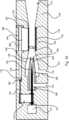
In diesem Zusammenhang ist ebenfalls die Möglichkeit gegeben, dass die Einstelleinrichtung eine Druckkammer umfasst, die ausgestaltet ist, die Membran zwischen der ersten und der zweiten Stellung zu verstellen, wenn ein dem Kupplungsmechanismus zugewiesener Kolben in die Druckkammer zumindest teilweise eingeschoben oder aus dieser zumindest teilweise herausgezogen wird. Damit macht sich die Einstelleinrichtung die Erkenntnis zu Nutze, dass Flüssigkeiten inkompressibel sind, so dass der Kolben beim fluiddichten Eindringen in die oder das Austreten aus der Druckkammer, deren Wand zumindest abschnittsweise aus der Membran besteht, die Membran verstellt, womit sich der Strömungsquerschnitt des Mischrohrs verändert. Als Flüssigkeit kommt beispielsweise eine Hydraulikflüssigkeit, wie Öl oder Alkohol, insbesondere eine Flüssigkeit mit geringer thermischer Ausdehnung, in Betracht.In this context, there is also the possibility that the adjusting device comprises a pressure chamber which is designed to adjust the membrane between the first and the second position when a piston assigned to the clutch mechanism is at least partially pushed into the pressure chamber or at least partially pulled out of it becomes. In this way, the setting device makes use of the knowledge that liquids are incompressible, so that the piston is able to penetrate or exit the pressure chamber in a fluid-tight manner, whose wall consists at least in sections of the membrane, the membrane adjusts, which changes the flow cross-section of the mixing tube. For example, a hydraulic fluid such as oil or alcohol, in particular a fluid with low thermal expansion, can be considered as the fluid.
Eine besonders kompakte Ausgestaltung des Ejektors lässt sich dadurch erreichen, dass der Kupplungsmechanismus aus einem, insbesondere mit einem Nadelkörper verbundenen, Zugelement oder einer Betätigungsstange gebildet ist. Damit ist gewährleistet, dass bei einer Verstellung der Nadel derart, dass der Strömungsquerschnitt der Treibdüse verringert wird, zugleich eine Verringerung des Strömungsquerschnitts des Mischrohrs einhergeht. Als Zugelement kann ein Faden, ein Draht, eine Schnur, ein Kabel oder dergleichen, Einsatz finden.A particularly compact embodiment of the ejector can be achieved in that the coupling mechanism is formed from a tension element or an actuating rod, in particular connected to a needle body. This ensures that when the needle is adjusted in such a way that the flow cross section of the driving nozzle is reduced, there is at the same time a reduction in the flow cross section of the mixing tube. A thread, a wire, a cord, a cable or the like can be used as the tension element.
Als vorteilhaft hat es sich weiterhin erwiesen, wenn der Kupplungsmechanismus eine Welle umfasst, die einenends mit der Einstelleinrichtung drehfest verbunden ist, und die derart ausgestaltet ist, mittels der axialen Verstellung der Nadel drehend angetrieben zu werden. Damit kann die Welle beispielsweise einen Draht, einen Faden, eine Schnur, ein Kabel oder dergleichen aufwickeln, wodurch sich der Strömungsquerschnitt der Membran und damit der Strömungsquerschnitt durch das Mischrohr verringert. Die Welle des Kupplungsmechanismus kann aber auch mit einer Einstelleinrichtung verbunden werden, die ein die Membran umgebendes Band umfasst, so dass beim Verdrehen der Welle das Band aufgewickelt und somit die Membran komprimiert wird. Beim Komprimieren der Membran wird also der Strömungsquerschnitt des Mischrohrs ebenfalls verringert.It has also proven to be advantageous if the coupling mechanism comprises a shaft which is connected at one end to the adjusting device in a rotationally fixed manner and which is designed such that it is driven to rotate by means of the axial adjustment of the needle. The shaft can thus wind up, for example, a wire, a thread, a cord, a cable or the like, as a result of which the flow cross section of the membrane and thus the flow cross section through the mixing tube is reduced. However, the shaft of the clutch mechanism can also be connected to an adjusting device which comprises a band surrounding the membrane, so that when the shaft is rotated the band is wound up and the membrane is thus compressed. When the membrane is compressed, the flow cross section of the mixing tube is also reduced.
Wenn die Bewegung der Nadel nicht eins zu eins auf die Bewegung der Membran angewendet werden soll, so hat es sich als vorteilhaft erwiesen, wenn der Kupplungsmechanismus ein Übersetzungsgetriebe umfasst, das derart ausgelegt ist, die axiale Bewegung der Nadel mit einem vorbestimmten Übersetzungsverhältnis auf die Bewegung der Membran zu übertragen.If the movement of the needle is not to be applied one to one to the movement of the diaphragm, it has proven to be advantageous if the coupling mechanism comprises a transmission gear which is designed in such a way that the axial movement of the needle with a predetermined transmission ratio to the movement to transmit the membrane.
Die für den erfindungsgemäßen Ejektor beschriebenen Vorteile und bevorzugten Ausführungsformen gelten auch für das erfindungsgemäße Brennstoffzellensystem.The advantages and preferred embodiments described for the ejector according to the invention also apply to the fuel cell system according to the invention.
Die vorstehend in der Beschreibung genannten Merkmale und Merkmalskombinationen sowie die nachfolgend in der Figurenbeschreibung genannten und/oder in den Figuren alleine gezeigten Merkmale und Merkmalskombinationen sind nicht nur in der jeweils angegebenen Kombination, sondern auch in anderen Kombinationen oder in Alleinstellung verwendbar, ohne den Rahmen der Erfindung zu verlassen. Es sind somit auch Ausführungen als von der Erfindung umfasst und offenbart anzusehen, die in den Figuren nicht explizit gezeigt oder erläutert sind, jedoch durch separierte Merkmalskombinationen aus den erläuterten Ausführungen hervorgehen und erzeugbar sind.The features and combinations of features mentioned above in the description and the features and combinations of features mentioned below in the description of the figures and / or shown alone in the figures can be used not only in the respectively specified combination but also in other combinations or on their own, without the scope of Leaving invention. Embodiments are therefore also to be regarded and encompassed by the invention, which are not explicitly shown or explained in the figures, but which emerge from the explanations explained and can be generated by separate combinations of features.
Weitere Vorteile, Merkmale und Einzelheiten der Erfindung ergeben sich aus den Ansprüchen, der nachfolgenden Beschreibung bevorzugter Ausführungsformen sowie anhand der Zeichnungen. Dabei zeigen:
1 eine Schnittansicht eines schematisch dargestellten Ejektors,2 den Schnitt I-I aus1 ,3 eine Schnittansicht eines weiteren schematisch dargestellten Ejektors,4 eine Schnittansicht eines weiteren schematisch dargestellten Ejektors,5 eine Schnittansicht eines weiteren schematisch dargestellten Ejektors,6 eine Schnittansicht eines weiteren schematisch dargestellten Ejektors,7 eine Schnittansicht eines weiteren schematisch dargestellten Ejektors,8 eine Schnittansicht eines weiteren schematisch dargestellten Ejektors,9 eine Schnittansicht eines weiteren schematisch dargestellten Ejektors,10 eine Schnittansicht eines weiteren schematisch dargestellten Ejektors,11 eine Schnittansicht eines weiteren schematisch dargestellten Ejektors,12 eine Schnittansicht eines weiteren schematisch dargestellten Ejektors,13 eine Schnittansicht eines weiteren schematisch dargestellten Ejektors,14 eine Schnittansicht eines weiteren schematisch dargestellten Ejektors,15 eine Schnittansicht eines weiteren schematisch dargestellten Ejektors,16 ein schematisch dargestellter Kupplungsteil des Kupplungsmechanismus des Ejektors nach15 ,17 eine Schnittansicht durch einen weiteren Kupplungsteil,18 eine Schnittansicht durch einen weiteren Kupplungsteil, und19 eine Schnittansicht eines nochmals weiteren Kupplungsteils.
1 2 shows a sectional view of a schematically illustrated ejector,2 section II1 .3 2 shows a sectional view of a further schematically illustrated ejector,4 2 shows a sectional view of a further schematically illustrated ejector,5 2 shows a sectional view of a further schematically illustrated ejector,6 2 shows a sectional view of a further schematically illustrated ejector,7 2 shows a sectional view of a further schematically illustrated ejector,8th 2 shows a sectional view of a further schematically illustrated ejector,9 2 shows a sectional view of a further schematically illustrated ejector,10 2 shows a sectional view of a further schematically illustrated ejector,11 2 shows a sectional view of a further schematically illustrated ejector,12 2 shows a sectional view of a further schematically illustrated ejector,13 2 shows a sectional view of a further schematically illustrated ejector,14 2 shows a sectional view of a further schematically illustrated ejector,15 2 shows a sectional view of a further schematically illustrated ejector,16 a schematically illustrated coupling part of the coupling mechanism of the ejector15 .17 2 shows a sectional view through a further coupling part,18 a sectional view through a further coupling part, and19 a sectional view of yet another coupling part.
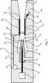
In den Figuren werden verschiedene Ejektoren beschrieben, wobei gleiche Bauteile mit den gleichen Bezugszeichen versehen sind. Alle Ejektoren weisen eine Saugdüse
Innerhalb der Treibdüse
Ein Strömungsquerschnitt
Wenn das Brennstoffzellensystem bei einer niedrigen Last betrieben werden soll, so werden die Strömungsquerschnitte
Vorliegend ist eine Innenwand
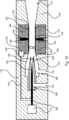
Bei dem in
In der Schnittansicht nach
Der Ejektor nach
In
Für die Auslegung des Kupplungsmechanismus
Der Ejektor nach
In
Um die Auslenkung der Membran
In
Im Hinblick auf die Führung der Versteifungselemente
In
Beim Ejektor nach
Dadurch wird das Band
Beim Ejektor nach
In
Die vorstehend beschriebenen Ejektoren zeichnen sich durch ihre flexible Anpassbarkeit an unterschiedliche Betriebsbedingungen eines Brennstoffzellensystems aus. Dies lässt sich insbesondere aufgrund der gekoppelten Bewegung der Nadel
BezugszeichenlisteLIST OF REFERENCE NUMBERS
- 100100
- Saugdüsesuction nozzle
- 102102
- Treibdüsepropelling nozzle
- 104104
- Mischrohrmixing tube
- 106106
- Einstelleinrichtungadjustment
- 108108
- Nadelneedle
- 110110
- Kupplungsmechanismusclutch mechanism
- 112112
- Aktuatoractuator
- 114114
- Diffusordiffuser
- 116116
- Anschluss (frischer Brennstoff)Connection (fresh fuel)
- 118118
- Anschluss (rezirkulierter Brennstoff)Connection (recirculated fuel)
- 120120
- Düsenöffnung (Treibdüse)Nozzle opening (driving nozzle)
- 122122
- Nadelspitzepinpoint
- 124124
- Düsenabschnitt (Treibdüse)Nozzle section (driving nozzle)
- 126126
- Düsenabschnitt (Saugdüse)Nozzle section (suction nozzle)
- 128128
- Innenwandinner wall
- 130130
- Membranmembrane
- 132132
- Versteifungselementstiffener
- 134 134
- Außenmantelouter sheath
- 136136
- Druckkammerpressure chamber
- 138138
- Kolbenpiston
- 140140
- Fadenthread
- 142142
- Nadelkörperneedle body
- 144144
- Ejektorkörperejector
- 146146
- Umlenkrollenguide rollers
- 148148
- Federelementspring element
- 150150
- Übersetzungsgetriebeup gear
- 152152
- zweiter Fadensecond thread
- 154154
- Gestängelinkage
- 156156
- Lagerungstorage
- 158158
- Zahnradgear
- 160160
- Zahnstangerack
- 162162
- Führungguide
- 164164
- Bandtape
- 166166
- Wellewave
- 168168
- Zwischenwelleintermediate shaft
- 170170
- zweite Verzahnungsecond toothing
- 172172
- Stirnradspur gear
- 174174
- Riementriebbelt drive
- 176176
- erster Wellenteilfirst shaft part
- 178178
- zweiter Wellenteilsecond shaft part
- 602602
- Strömungsquerschnitt (Mischrohr)Flow cross-section (mixing tube)
- 604604
- Strömungsquerschnitt (Treibdüse)Flow cross-section (driving nozzle)
ZITATE ENTHALTEN IN DER BESCHREIBUNG QUOTES INCLUDE IN THE DESCRIPTION
Diese Liste der vom Anmelder aufgeführten Dokumente wurde automatisiert erzeugt und ist ausschließlich zur besseren Information des Lesers aufgenommen. Die Liste ist nicht Bestandteil der deutschen Patent- bzw. Gebrauchsmusteranmeldung. Das DPMA übernimmt keinerlei Haftung für etwaige Fehler oder Auslassungen.This list of documents listed by the applicant has been generated automatically and is only included for the better information of the reader. The list is not part of the German patent or utility model application. The DPMA assumes no liability for any errors or omissions.
Zitierte PatentliteraturPatent literature cited
- US 2014/0212776 A1 [0005]US 2014/0212776 A1 [0005]
- EP 2204562 A2 [0005]EP 2204562 A2 [0005]
- WO 2017/018162 A1 [0005]WO 2017/018162 A1 [0005]
- DE 102015216457 A1 [0005]DE 102015216457 A1 [0005]
- US 9696069 B2 [0005]US 9696069 B2 [0005]
- US 6858340 B2 [0005]US 6858340 B2 [0005]
Claims (10)
Translated fromGermanPriority Applications (2)
| Application Number | Priority Date | Filing Date | Title |
|---|---|---|---|
| DE102018214376.5ADE102018214376A1 (en) | 2018-08-24 | 2018-08-24 | Ejector for a fuel cell system and fuel cell system |
| US16/550,070US11156234B2 (en) | 2018-08-24 | 2019-08-23 | Ejector for a fuel cell system and fuel cell system |
Applications Claiming Priority (1)
| Application Number | Priority Date | Filing Date | Title |
|---|---|---|---|
| DE102018214376.5ADE102018214376A1 (en) | 2018-08-24 | 2018-08-24 | Ejector for a fuel cell system and fuel cell system |
Publications (1)
| Publication Number | Publication Date |
|---|---|
| DE102018214376A1true DE102018214376A1 (en) | 2020-02-27 |
Family
ID=69413129
Family Applications (1)
| Application Number | Title | Priority Date | Filing Date |
|---|---|---|---|
| DE102018214376.5AWithdrawnDE102018214376A1 (en) | 2018-08-24 | 2018-08-24 | Ejector for a fuel cell system and fuel cell system |
Country Status (2)
| Country | Link |
|---|---|
| US (1) | US11156234B2 (en) |
| DE (1) | DE102018214376A1 (en) |
Cited By (4)
| Publication number | Priority date | Publication date | Assignee | Title |
|---|---|---|---|---|
| DE102019208521A1 (en)* | 2019-06-12 | 2020-12-17 | Robert Bosch Gmbh | Delivery unit for a fuel cell system for delivering and / or controlling a gaseous medium |
| DE102020108650A1 (en) | 2020-03-30 | 2021-09-30 | Audi Aktiengesellschaft | Ejector |
| DE102020123931A1 (en) | 2020-09-15 | 2022-03-17 | Audi Aktiengesellschaft | Method for operating a fuel cell device, fuel cell device and motor vehicle with a fuel cell device |
| WO2022100978A1 (en)* | 2020-11-13 | 2022-05-19 | Robert Bosch Gmbh | Fuel conveying device for conveying a fuel for a fuel cell system, fuel cell system and method for operating a fuel conveying device for conveying a fuel for a fuel cell system |
Families Citing this family (8)
| Publication number | Priority date | Publication date | Assignee | Title |
|---|---|---|---|---|
| CN114135525B (en)* | 2020-09-02 | 2024-03-26 | 中国石油化工股份有限公司 | Adjustable ejector and gas-liquid mixing and conveying system for high-pressure gas well and low-pressure gas well |
| CN114718915B (en)* | 2022-03-09 | 2024-10-29 | 英飞同仁风机股份有限公司 | High-impact fan induction nozzle |
| AT525873B1 (en) | 2022-10-12 | 2023-09-15 | Singer Gerald | Ejector for supplying hydrogen to at least one fuel cell |
| FR3146030B1 (en)* | 2023-02-21 | 2025-06-20 | Novares France | Fuel cell ejector |
| AT526673B1 (en)* | 2023-03-10 | 2024-06-15 | Avl List Gmbh | Ejector device for a fuel cell system |
| AT526672B1 (en)* | 2023-03-10 | 2024-06-15 | Avl List Gmbh | Ejector device for a fuel cell system |
| FR3158597A1 (en)* | 2024-01-19 | 2025-07-25 | Novares France | Fuel cell ejector |
| US20250271004A1 (en)* | 2024-02-23 | 2025-08-28 | Honeywell International Inc. | Jet pump system |
Citations (2)
| Publication number | Priority date | Publication date | Assignee | Title |
|---|---|---|---|---|
| US4595344A (en)* | 1982-09-30 | 1986-06-17 | Briley Patrick B | Ejector and method of controlling same |
| DE10036045C1 (en)* | 2000-07-25 | 2001-10-04 | Festo Ag & Co | Vacuum ejector has high velocity nozzle followed by diffuser channel with cross section which can be varied in accordance with process requirements |
Family Cites Families (9)
| Publication number | Priority date | Publication date | Assignee | Title |
|---|---|---|---|---|
| US267022A (en)* | 1882-11-07 | Steam jet injector and exhauster | ||
| JP2002227799A (en)* | 2001-02-02 | 2002-08-14 | Honda Motor Co Ltd | Variable flow rate ejector and fuel cell system provided with the variable flow rate ejector |
| US8083495B2 (en)* | 2008-08-14 | 2011-12-27 | General Electric Company | Ejectors with separably secured nozzles, adjustable size nozzles, or adjustable size mixing tubes |
| US8142169B2 (en) | 2009-01-06 | 2012-03-27 | General Electric Company | Variable geometry ejector |
| WO2012092685A1 (en) | 2011-01-04 | 2012-07-12 | Carrier Corporation | Ejector |
| US9601788B2 (en)* | 2013-01-25 | 2017-03-21 | Ford Global Technologies, Llc | Varying wall geometry ejector |
| JP6144854B1 (en) | 2015-07-29 | 2017-06-07 | 株式会社テイエルブイ | Ejecta |
| DE102015216457A1 (en) | 2015-08-27 | 2017-03-02 | Volkswagen Aktiengesellschaft | Jet pumps for a fuel cell system and a fuel cell system |
| EP3438466B1 (en)* | 2016-04-01 | 2020-04-01 | TLV Co., Ltd. | Ejector, ejector production method, and method for setting outlet flow path of diffuser |
- 2018
- 2018-08-24DEDE102018214376.5Apatent/DE102018214376A1/ennot_activeWithdrawn
- 2019
- 2019-08-23USUS16/550,070patent/US11156234B2/enactiveActive
Patent Citations (2)
| Publication number | Priority date | Publication date | Assignee | Title |
|---|---|---|---|---|
| US4595344A (en)* | 1982-09-30 | 1986-06-17 | Briley Patrick B | Ejector and method of controlling same |
| DE10036045C1 (en)* | 2000-07-25 | 2001-10-04 | Festo Ag & Co | Vacuum ejector has high velocity nozzle followed by diffuser channel with cross section which can be varied in accordance with process requirements |
Cited By (4)
| Publication number | Priority date | Publication date | Assignee | Title |
|---|---|---|---|---|
| DE102019208521A1 (en)* | 2019-06-12 | 2020-12-17 | Robert Bosch Gmbh | Delivery unit for a fuel cell system for delivering and / or controlling a gaseous medium |
| DE102020108650A1 (en) | 2020-03-30 | 2021-09-30 | Audi Aktiengesellschaft | Ejector |
| DE102020123931A1 (en) | 2020-09-15 | 2022-03-17 | Audi Aktiengesellschaft | Method for operating a fuel cell device, fuel cell device and motor vehicle with a fuel cell device |
| WO2022100978A1 (en)* | 2020-11-13 | 2022-05-19 | Robert Bosch Gmbh | Fuel conveying device for conveying a fuel for a fuel cell system, fuel cell system and method for operating a fuel conveying device for conveying a fuel for a fuel cell system |
Also Published As
| Publication number | Publication date |
|---|---|
| US20200067112A1 (en) | 2020-02-27 |
| US11156234B2 (en) | 2021-10-26 |
Similar Documents
| Publication | Publication Date | Title |
|---|---|---|
| DE102018214376A1 (en) | Ejector for a fuel cell system and fuel cell system | |
| DE4132281C2 (en) | ||
| DE10214174A1 (en) | Curvature actuator for an endoscope | |
| DE102014223502A1 (en) | Drive arrangement for a vehicle and vehicle with the drive assembly | |
| DE2400141A1 (en) | SAFETY BELT RETRACTOR | |
| DE102011080082A1 (en) | Bearing device with cable guide for an electric vehicle | |
| DE102017222811A1 (en) | Steering gear and steering system for a motor vehicle | |
| DE2558235A1 (en) | ELECTRIC SHARPENER FOR PENCILS OR THE SAME | |
| DE102021102267A1 (en) | Endoscope with a rack and pinion control | |
| DE102016122442A1 (en) | Pressing device for pressing a fuel cell stack and fuel cell device with pressing device | |
| DE19548593A1 (en) | Mechanism for conversion of rotation to translation and vice-versa | |
| DE102016009932A1 (en) | Device for supplying air to a fuel cell | |
| DE102019209765A1 (en) | Ejector, ejector set, method for operating an ejector, fuel cell system and motor vehicle | |
| DE102021105044A1 (en) | ejector | |
| DE102020108650A1 (en) | Ejector | |
| DE102012205946A1 (en) | Transmission device, particularly for wind turbine, has bearing unit performed as bearing unit that runs with planetary carrier, where planetary carrier and subsequent stage are supported against one another in axial manner | |
| DE102018126071A1 (en) | Linear actuator, especially for a vehicle clutch | |
| DE10118645A1 (en) | Initiation and transmission of the shift movement in a bicycle transmission | |
| WO2023066619A1 (en) | Jet pump module for a fuel cell system, fuel cell system | |
| DE102021101419A1 (en) | Sun protection system with a pull system | |
| DE102015219052A1 (en) | Linear actuator and motor-generator assembly | |
| DE102004022539A1 (en) | Moisture exchange module with a bundle of moisture permeable hollow fiber membranes | |
| DE4329162A1 (en) | Endoscope with movable front terminal region | |
| AT525873B1 (en) | Ejector for supplying hydrogen to at least one fuel cell | |
| DE102024109859B3 (en) | Independent wheel drive system for a motor vehicle and motor vehicle with such an independent wheel drive system |
Legal Events
| Date | Code | Title | Description |
|---|---|---|---|
| R163 | Identified publications notified | ||
| R082 | Change of representative | Representative=s name:HENTRICH PATENT- & RECHTSANWALTSPARTNERSCHAFT , DE Representative=s name:HENTRICH PATENT- & RECHTSANWAELTE PARTG MBB, DE Representative=s name:HENTRICH PATENTANWAELTE PARTG MBB, DE | |
| R119 | Application deemed withdrawn, or ip right lapsed, due to non-payment of renewal fee |