DE102018210524A1 - Process for charging battery packs for power tools and charger for carrying out the process - Google Patents
Process for charging battery packs for power tools and charger for carrying out the processDownload PDFInfo
- Publication number
- DE102018210524A1 DE102018210524A1DE102018210524.3ADE102018210524ADE102018210524A1DE 102018210524 A1DE102018210524 A1DE 102018210524A1DE 102018210524 ADE102018210524 ADE 102018210524ADE 102018210524 A1DE102018210524 A1DE 102018210524A1
- Authority
- DE
- Germany
- Prior art keywords
- charging
- charger
- battery pack
- mode
- charging mode
- Prior art date
- Legal status (The legal status is an assumption and is not a legal conclusion. Google has not performed a legal analysis and makes no representation as to the accuracy of the status listed.)
- Pending
Links
- 238000007600chargingMethods0.000titleclaimsabstractdescription178
- 238000000034methodMethods0.000titleclaimsabstractdescription35
- 230000008569processEffects0.000titleclaimsdescription14
- 230000003287optical effectEffects0.000claimsdescription3
- 230000001960triggered effectEffects0.000claims1
- 238000003860storageMethods0.000description10
- 229910001416lithium ionInorganic materials0.000description7
- 238000010281constant-current constant-voltage chargingMethods0.000description6
- 238000005457optimizationMethods0.000description3
- 238000004891communicationMethods0.000description2
- 238000013461designMethods0.000description2
- 238000010586diagramMethods0.000description2
- 238000005553drillingMethods0.000description2
- 230000001939inductive effectEffects0.000description2
- 238000003825pressingMethods0.000description2
- BUHVIAUBTBOHAG-FOYDDCNASA-N(2r,3r,4s,5r)-2-[6-[[2-(3,5-dimethoxyphenyl)-2-(2-methylphenyl)ethyl]amino]purin-9-yl]-5-(hydroxymethyl)oxolane-3,4-diolChemical compoundCOC1=CC(OC)=CC(C(CNC=2C=3N=CN(C=3N=CN=2)[C@H]2[C@@H]([C@H](O)[C@@H](CO)O2)O)C=2C(=CC=CC=2)C)=C1BUHVIAUBTBOHAG-FOYDDCNASA-N0.000description1
- WHXSMMKQMYFTQS-UHFFFAOYSA-NLithiumChemical compound[Li]WHXSMMKQMYFTQS-UHFFFAOYSA-N0.000description1
- 229910005580NiCdInorganic materials0.000description1
- 230000000903blocking effectEffects0.000description1
- 230000008859changeEffects0.000description1
- QVFWZNCVPCJQOP-UHFFFAOYSA-NchloralodolChemical compoundCC(O)(C)CC(C)OC(O)C(Cl)(Cl)ClQVFWZNCVPCJQOP-UHFFFAOYSA-N0.000description1
- 239000003086colorantSubstances0.000description1
- 238000010276constructionMethods0.000description1
- 230000003247decreasing effectEffects0.000description1
- 238000011161developmentMethods0.000description1
- 238000005516engineering processMethods0.000description1
- 238000009434installationMethods0.000description1
- 239000010985leatherSubstances0.000description1
- 229910052744lithiumInorganic materials0.000description1
- 238000003754machiningMethods0.000description1
- 229920003023plasticPolymers0.000description1
- 238000005498polishingMethods0.000description1
- APTZNLHMIGJTEW-UHFFFAOYSA-Npyraflufen-ethylChemical compoundC1=C(Cl)C(OCC(=O)OCC)=CC(C=2C(=C(OC(F)F)N(C)N=2)Cl)=C1FAPTZNLHMIGJTEW-UHFFFAOYSA-N0.000description1
- 238000012546transferMethods0.000description1
- 230000007704transitionEffects0.000description1
Images


Classifications
- H—ELECTRICITY
- H02—GENERATION; CONVERSION OR DISTRIBUTION OF ELECTRIC POWER
- H02J—CIRCUIT ARRANGEMENTS OR SYSTEMS FOR SUPPLYING OR DISTRIBUTING ELECTRIC POWER; SYSTEMS FOR STORING ELECTRIC ENERGY
- H02J7/00—Circuit arrangements for charging or depolarising batteries or for supplying loads from batteries
- H02J7/0069—Charging or discharging for charge maintenance, battery initiation or rejuvenation
- H—ELECTRICITY
- H01—ELECTRIC ELEMENTS
- H01M—PROCESSES OR MEANS, e.g. BATTERIES, FOR THE DIRECT CONVERSION OF CHEMICAL ENERGY INTO ELECTRICAL ENERGY
- H01M10/00—Secondary cells; Manufacture thereof
- H01M10/42—Methods or arrangements for servicing or maintenance of secondary cells or secondary half-cells
- H01M10/44—Methods for charging or discharging
- H01M10/441—Methods for charging or discharging for several batteries or cells simultaneously or sequentially
- H—ELECTRICITY
- H01—ELECTRIC ELEMENTS
- H01M—PROCESSES OR MEANS, e.g. BATTERIES, FOR THE DIRECT CONVERSION OF CHEMICAL ENERGY INTO ELECTRICAL ENERGY
- H01M10/00—Secondary cells; Manufacture thereof
- H01M10/42—Methods or arrangements for servicing or maintenance of secondary cells or secondary half-cells
- H01M10/46—Accumulators structurally combined with charging apparatus
- H—ELECTRICITY
- H01—ELECTRIC ELEMENTS
- H01M—PROCESSES OR MEANS, e.g. BATTERIES, FOR THE DIRECT CONVERSION OF CHEMICAL ENERGY INTO ELECTRICAL ENERGY
- H01M10/00—Secondary cells; Manufacture thereof
- H01M10/42—Methods or arrangements for servicing or maintenance of secondary cells or secondary half-cells
- H01M10/48—Accumulators combined with arrangements for measuring, testing or indicating the condition of cells, e.g. the level or density of the electrolyte
- H01M10/488—Cells or batteries combined with indicating means for external visualization of the condition, e.g. by change of colour or of light density
- H—ELECTRICITY
- H02—GENERATION; CONVERSION OR DISTRIBUTION OF ELECTRIC POWER
- H02J—CIRCUIT ARRANGEMENTS OR SYSTEMS FOR SUPPLYING OR DISTRIBUTING ELECTRIC POWER; SYSTEMS FOR STORING ELECTRIC ENERGY
- H02J7/00—Circuit arrangements for charging or depolarising batteries or for supplying loads from batteries
- H02J7/007—Regulation of charging or discharging current or voltage
- H02J7/00712—Regulation of charging or discharging current or voltage the cycle being controlled or terminated in response to electric parameters
- H02J7/00714—Regulation of charging or discharging current or voltage the cycle being controlled or terminated in response to electric parameters in response to battery charging or discharging current
- H02J7/00716—Regulation of charging or discharging current or voltage the cycle being controlled or terminated in response to electric parameters in response to battery charging or discharging current in response to integrated charge or discharge current
- H—ELECTRICITY
- H01—ELECTRIC ELEMENTS
- H01M—PROCESSES OR MEANS, e.g. BATTERIES, FOR THE DIRECT CONVERSION OF CHEMICAL ENERGY INTO ELECTRICAL ENERGY
- H01M50/00—Constructional details or processes of manufacture of the non-active parts of electrochemical cells other than fuel cells, e.g. hybrid cells
- H01M50/20—Mountings; Secondary casings or frames; Racks, modules or packs; Suspension devices; Shock absorbers; Transport or carrying devices; Holders
- H01M50/204—Racks, modules or packs for multiple batteries or multiple cells
- H01M50/207—Racks, modules or packs for multiple batteries or multiple cells characterised by their shape
- H01M50/213—Racks, modules or packs for multiple batteries or multiple cells characterised by their shape adapted for cells having curved cross-section, e.g. round or elliptic
- Y—GENERAL TAGGING OF NEW TECHNOLOGICAL DEVELOPMENTS; GENERAL TAGGING OF CROSS-SECTIONAL TECHNOLOGIES SPANNING OVER SEVERAL SECTIONS OF THE IPC; TECHNICAL SUBJECTS COVERED BY FORMER USPC CROSS-REFERENCE ART COLLECTIONS [XRACs] AND DIGESTS
- Y02—TECHNOLOGIES OR APPLICATIONS FOR MITIGATION OR ADAPTATION AGAINST CLIMATE CHANGE
- Y02E—REDUCTION OF GREENHOUSE GAS [GHG] EMISSIONS, RELATED TO ENERGY GENERATION, TRANSMISSION OR DISTRIBUTION
- Y02E60/00—Enabling technologies; Technologies with a potential or indirect contribution to GHG emissions mitigation
- Y02E60/10—Energy storage using batteries
Landscapes
- Engineering & Computer Science (AREA)
- Power Engineering (AREA)
- Manufacturing & Machinery (AREA)
- Chemical & Material Sciences (AREA)
- Chemical Kinetics & Catalysis (AREA)
- Electrochemistry (AREA)
- General Chemical & Material Sciences (AREA)
- Charge And Discharge Circuits For Batteries Or The Like (AREA)
- Secondary Cells (AREA)
Abstract
Translated fromGermanDescription
Translated fromGermanDie Erfindung betrifft ein Verfahren zum Aufladen von Akkupacks für Elektrowerkzeugmaschinen sowie ein Ladegerät zur Durchführung des Verfahrens nach der Gattung der unabhängigen Ansprüche.The invention relates to a method for charging battery packs for power tools and a charger for performing the method according to the preamble of the independent claims.
Stand der TechnikState of the art
Heutige Akkupacks für Elektrowerkzeuge enthalten typischerweise Litium-Ionen-Zellen (Li-Ion), die mit gängigen Ladegeräten in der Regel in einem sogenannten CCCV-Verfahren (Constant Current Constant Voltage) aufgeladen werden. Dabei generiert eine Ladeelektronik des Ladegeräts einen konstanter Ladestrom durch den Akkupack (CC Phase), so dass die Akkuspannung steigt. Sobald die maximale Akkuspannung erreicht ist, wird diese von der Ladeelektronik konstant gehalten (CV Phase) und der Ladestrom reduziert. Ist ein vordefinierter Minimalwert des Ladestroms erreicht, beendet die Ladeelektronik den Ladevorgang und die Akkuzellen sind vollgeladen. Der Übergang von der CC- zur CV-Phase erfolgt typischerweise bei einem Ladezustand von ca. 80 %. Bei hohen Ladeströmen dauern CC-Phase und CV-Phase in etwa gleich lang. Daher weisen die Zeitspannen, bis ein Akkupack auf ca. 80 % geladen ist und bis der Akkupack um die restlichen 20 % auf 100 % geladen wurde, auch nahezu die gleiche Länge auf.Today's battery packs for power tools typically contain lithium-ion cells (Li-Ion), which are usually charged using a conventional charger in a so-called CCCV process (Constant Current Constant Voltage). Charging electronics of the charger generate a constant charging current through the battery pack (CC phase), so that the battery voltage increases. As soon as the maximum battery voltage is reached, the charging electronics keep it constant (CV phase) and the charging current is reduced. If a predefined minimum value of the charging current is reached, the charging electronics end the charging process and the battery cells are fully charged. The transition from the CC to the CV phase typically takes place at a charge level of approx. 80%. At high charging currents, the CC phase and CV phase last approximately the same length. Therefore, the time periods until a battery pack is charged to approx. 80% and until the battery pack has been charged by the remaining 20% to 100% also have almost the same length.
In der Regel sind die erforderlichen Ladeparameter zum Aufladen von Akkupacks für Elektrowerkzeugmaschinen fest in der Ladeelektronik der Ladegeräte einprogrammiert. So werden üblicherweise für jedes Ladegerät und für jeden Akkupack die Parameter eingesetzt, die der Hersteller als optimal für die durchschnittliche Nutzung der Akkupacks erachtet. Diese Parameter werden von der Ladeelektronik des Ladegeräts an den jeweils eingesteckten Akkupack angepasst. Dies erfolgt in der Regel über eine Kodierung (zum Beispiel mittels eines Kodier-Widerstands) des Akkupacks, die die Ladeelektronik des Ladegeräts erkennen kann, oder über eine Kommunikationsschnittstelle (zum Beispiel BUS-Kommunikation zwischen Akkupack und Ladegerät).As a rule, the charging parameters required for charging battery packs for power tools are permanently programmed into the charging electronics of the chargers. For example, the parameters that the manufacturer considers optimal for the average use of the battery packs are usually used for each charger and for each battery pack. The charging electronics of the charger adapt these parameters to the respective inserted battery pack. This is usually done via coding (for example by means of a coding resistor) of the battery pack, which the charging electronics of the charger can recognize, or via a communication interface (for example, BUS communication between the battery pack and the charger).
Durch die Entwicklung der Li-Ion-Technologie ist es möglich, immer mehr unterschiedliche Anwendungen und Produkte mit Li-lon-Akkupacks und -Zellen zu betreiben. Die Erwartungen an Ladezeit, Energie und Lebensdauer können durch die Vielfalt der Produkte und Anwendungen stark variieren. Dabei steht die Optimierung der Lebensdauer jedoch oft im Gegensatz zur Optimierung der Ladezeit oder der eingeladenen Kapazität, sprich, der Energie, die nach dem Laden in dem Akkupack bzw. den -zellen zur Verfügung steht.The development of Li-ion technology makes it possible to operate more and more different applications and products with Li-ion battery packs and cells. Expectations regarding charging time, energy and lifespan can vary greatly due to the variety of products and applications. However, the optimization of the service life is often in contrast to the optimization of the charging time or the charged capacity, i.e. the energy that is available in the battery pack or cells after charging.
Aus der
Aus der
Elektrowerkzeugmaschinen einer Spannungsklasse können sehr unterschiedliche Eigenschaften haben, wie zum Beispiel einen hohen Leistungsbedarf für eine kurze Laufzeit oder einen niedrigen Leistungsbedarf bei einer längeren Laufzeit. Ferner können diese Elektrowerkzeugmaschinen in Unternehmen von vielen Anwendern mit sehr unterschiedlichen Anforderungsprofilen genutzt werden, so dass sich entsprechend unterschiedliche Anforderungen an die die Elektrowerkzeugmaschienen versorgenden Akkupacks und deren Ladeparameter ergeben.Power tool machines of a voltage class can have very different properties, such as a high power requirement for a short runtime or a low power requirement for a longer runtime. Furthermore, these electric machine tools can be used in companies by many users with very different requirement profiles, so that there are correspondingly different requirements for the battery packs supplying the electric machine tools and their charging parameters.
Es ist Aufgabe der Erfindung, die Ladeparameter von Akkupacks für Elektrowerkzeugmaschinen hinsichtlich der verschiedenen Eigenschaften wie zum Beispiel der Ladezeit, der eingeladenen Kapazität (und damit der Laufzeit in einem Elektrowerkzeug) oder der Lebensdauer des Akkupacks bzw. der Akkuzellen (in Nutzung oder in Lagerung) gegenüber dem bekannten Stand der Technik weiter zu optimieren und an die jeweilige Situation anzupassen, um eine bestmögliche Nutzung der Akkupacks für unterschiedliche Anwendungen der Elektrowerkzeugmaschinen zu ermöglichen.It is the object of the invention to determine the charging parameters of battery packs for power tool machines with regard to the various properties, such as the charging time, the charged capacity (and thus the running time in a power tool) or the service life of the battery pack or the battery cells (in use or in storage). Compared to the known state of the art to optimize further and adapt to the particular situation in order to enable the best possible use of the battery packs for different applications of power tools.
Vorteile der ErfindungAdvantages of the invention
Die Erfindung betrifft ein Verfahren zum Aufladen von Akkupacks für Elektrowerkzeugmaschinen mittels eines Ladegeräts, wobei das Ladegerät einen ersten Lademodus aufweist, in dem die Akkupacks bis zu einem definierten Ladezustand mit einem konstanten Strom und nachfolgend mit einen konstanten Spannung geladen werden. Erfindungsgemäß ist vorgesehen, dass durch einen Anwender zumindest ein zweiter Lademodus einstellbar ist, in dem die Akkupacks ausschließlich mit einem konstanten Strom bis zu einer Ladegrenze nur teilgeladen werden. Mit besonderem Vorteil lassen sich auf diese Weise die Ladeparameter an die jeweilige Situation anpassen, um eine optimale Verwendung der Akkupacks zu ermöglichen, so dass die Ladezeit, die eingeladene Kapazität bzw. die Laufzeit in Verbindung mit der Elektrowerkzeugmaschine und die Lebensdauer der Akkupacks bzw. Akkuzellen gezielt optimiert werden können.The invention relates to a method for charging battery packs for power tools by means of a charger, the charger having a first charging mode in which the battery packs are charged with a constant current up to a defined charge state and subsequently with a constant voltage. According to the invention, it is provided that at least one second charging mode can be set by a user, in which the battery packs are only partially charged with a constant current up to a charging limit. In this way, the Adapt the charging parameters to the respective situation in order to enable the battery packs to be used optimally, so that the charging time, the charged capacity or the runtime in connection with the power tool and the service life of the battery packs or battery cells can be specifically optimized.
Als akkubetriebene „Elektrowerkzeugmaschine“ soll zum einen jedes Gerät zur Bearbeitung von Werkstücken mittels eines elektrisch angetriebenen Einsatzwerkzeugs verstanden werden. Somit kann die Elektrowerkzeugmaschine als Elektrohandwerkzeug oder als stationäre Elektrowerkzeugmaschine ausgebildet sein. Typische Elektrowerkzeugmaschinen sind in diesem Zusammenhang Hand- oder Standbohrmaschinen, Schrauber, Schlagbohrmaschinen, Hobel, Winkelschleifer, Schwingschleifer, Poliermaschinen oder dergleichen. Aber auch Gartengeräte wie Rasentrimmer, Astsägen oder dergleichen lassen sich unter dem Begriff Elektrowerkzeugmaschine subsumieren. Weiterhin sollen Geräte als Elektrowerkzeugmaschinen verstanden werden, die typischerweise auf Baustellen zum Einsatz kommen. Beispiele hierfür sind Gebläse, Pumpen, Mischmaschinen, etc.On the one hand, a battery-operated “power tool” should be understood to mean any device for machining workpieces by means of an electrically driven insert tool. The electric machine tool can thus be designed as an electric hand tool or as a stationary electric machine tool. Typical power tools in this context are hand or stand drilling machines, screwdrivers, impact drills, planes, angle grinders, orbital sanders, polishing machines or the like. Garden tools such as lawn trimmers, branch saws or the like can also be subsumed under the term power tool. Furthermore, devices are to be understood as electrical machine tools that are typically used on construction sites. Examples include blowers, pumps, mixing machines, etc.
Die hier beschriebenen Akkupacks für Elektrowerkzeugmaschinen sind vorzugsweise als Wechselakkupacks ausgebildet und weisen ein Gehäuse auf, das über eine mechanische Schnittstelle kraft- und/oder formschlüssig lösbar mit der Elektrowerkzeugmaschine oder dem Ladegerät verbindbar ist. Des Weiteren umfasst der Akkupack zumindest eine Akkuzelle und eine elektrische Schnittstelle, über die die zumindest eine Akkuzelle mit der Elektrowerkzeugmaschine oder dem Ladegerät elektrisch verbindbar ist. Die Akkuzelle kann als eine galvanische Zelle ausgebildet sein, die einen Aufbau aufweist, bei dem ein Zellpol an einem Ende und ein weiterer Zellpol an einem gegenüberliegenden Ende zu liegen kommen. Insbesondere weist die Akkuzelle an einem Ende einen positiven Zellpol und an einem gegenüberliegenden Ende einen negativen Zellpol auf. Bevorzugt sind die Akkuzellen als lithiumbasierte Akkuzellen, z.B. Li-Ion, Li-Po oder dergleichen, ausgebildet. Die Erfindung ist aber auch auf NiCd-, NiMh-Zellen oder andere geeignete Zellenarten anwendbar. Die Akkuspannung des Akkupacks ist in der Regel ein Vielfaches der Spannung einer einzelnen Akkuzelle und ergibt sich aus der Verschaltung (parallel oder seriell) der Akkuzellen. Bei gängigen Li-Ion-Akkuzellen mit einer Spannung von 3,6 V ergeben sich somit beispielhafte Akkuspannungen von 3,6 V, 7,2 V, 10, 8 V, 14,4 V, 18 V, 36 V etc. Bevorzugt ist die Akkuzelle als zumindest im Wesentlichen zylinderförmige Rundzelle ausgebildet, wobei die Zellpole an Enden der Zylinderform angeordnet sind. Die elektrische Schnittstelle umfasst insbesondere zumindest zwei elektrische Kontaktelemente, die zur Übertragung von Energie ausgebildet sind. Alternativ kann die elektrische Schnittstelle aber auch ein sekundäres Ladespulenelement zur induktiven Ladung aufweisen. Zusätzlich kann die elektrische Schnittstelle weitere Kontaktelemente aufweisen, die dazu ausgebildet sind, Informationen, die vorzugsweise über eine in den Akkupack integrierte Elektronik ermittelt werden, an die Elektrowerkzeugmaschine und/oder das Ladegerät zu übertragen. Dabei kann es sich beispielsweise um einen Ladezustand des Akkupacks, eine Temperatur innerhalb des Akkupacks, eine Codierung oder einer Restkapazität des Akkupacks handeln.The battery packs for power tool machines described here are preferably designed as exchangeable battery packs and have a housing that can be connected to the power tool or the charger in a non-positive and / or positive manner via a mechanical interface. Furthermore, the battery pack comprises at least one battery cell and an electrical interface, via which the at least one battery cell can be electrically connected to the power tool or the charger. The battery cell can be designed as a galvanic cell which has a structure in which a cell pole comes to lie at one end and another cell pole lies at an opposite end. In particular, the battery cell has a positive cell pole at one end and a negative cell pole at an opposite end. The battery cells are preferably lithium-based battery cells, e.g. Li-ion, Li-Po or the like. However, the invention is also applicable to NiCd, NiMh cells or other suitable cell types. The battery voltage of the battery pack is usually a multiple of the voltage of a single battery cell and results from the connection (parallel or serial) of the battery cells. In the case of common Li-ion battery cells with a voltage of 3.6 V, exemplary battery voltages of 3.6 V, 7.2 V, 10, 8 V, 14.4 V, 18 V, 36 V etc. result the battery cell is designed as an at least substantially cylindrical round cell, the cell poles being arranged at the ends of the cylindrical shape. The electrical interface comprises in particular at least two electrical contact elements which are designed to transmit energy. Alternatively, the electrical interface can also have a secondary charging coil element for inductive charging. In addition, the electrical interface can have further contact elements which are designed to transmit information, which is preferably determined via electronics integrated in the battery pack, to the power tool and / or the charger. This can be, for example, a state of charge of the battery pack, a temperature inside the battery pack, coding or a residual capacity of the battery pack.
Es sei angemerkt, dass die Erfindung nicht auf Wechselakkupacks beschränkt ist, sondern ohne Einschränkung auch für Elektrowerkzeugmaschinen mit fest integrierten Akkuzellen anwendbar ist. Der Begriff Akkupack soll daher als Synonym für Wechselakkupacks für Elektrowerkzeugmaschinen als auch für Elektrowerkzeugmaschinen mit fest integrierten Akkuzellen verstanden werden. Weiterhin soll ein Einstecken des Akkupacks bzw. der Elektrowerkzeugmaschine auch als ein Einschieben, Einsetzen oder ein vergleichbarer Verbindungsvorgang verstanden werden.It should be noted that the invention is not limited to exchangeable battery packs, but can also be used without restriction for power tool machines with permanently integrated battery cells. The term battery pack should therefore be understood as a synonym for exchangeable battery packs for power tool machines as well as for power tool machines with permanently integrated battery cells. Furthermore, inserting the battery pack or the electric machine tool should also be understood as inserting, inserting or a comparable connection process.
Der Begriff „Ladegrenze“ soll einen Zielwert der Ladekapazität eines Akkupacks definieren, bis zu dem der Akkupack aufgeladen werden soll. Bei Erreichen der Ladegrenze wird der Akkupack nicht weiter geladen und das Ladegerät beendet selbsttätig den jeweiligen Ladevorgang des eingestellten Lademodus.The term “charging limit” is intended to define a target value for the charging capacity of a battery pack up to which the battery pack is to be charged. When the charge limit is reached, the battery pack is no longer charged and the charger automatically ends the respective charging process of the set charging mode.
Es ist vorgesehen, dass das Ladegerät neben dem ersten und dem zweiten Lademodus noch weitere Lademodus aufweist, wobei in den weiteren Lademodus die Akkupacks mit konstantem Strom bis zu jeweils unterschiedlichen Ladegrenzen nur teilgeladen werden. Da jeder Lademodus über einen eigenen Ladeparametersatz verfügt, ist somit in vorteilhafter Weise anhand des ausgewählten Ladeverfahrens eine Optimierung der Ladezeit, der eingeladenen Kapazität und der Lebensdauer der aufzuladenden Akkupacks einerseits sowie der Laufzeit der Elektrowerkzeugmaschine und der für sie bereitgestellten Energie andererseits für den jeweiligen spezifischen Nutzungsfall möglich.It is envisaged that the charger has, in addition to the first and the second charging mode, further charging modes, the battery packs being only partially charged with constant current up to different charging limits in the further charging mode. Since each charging mode has its own charging parameter set, an optimization of the charging time, the charged capacity and the service life of the battery packs to be charged, on the one hand, and the runtime of the power tool and the energy provided for it, on the other hand, is advantageous for the respective specific use case possible.
Zudem ermöglichen spezielle Lademodus das Erreichen eines präzisen Ladezustands (State of Charge), wobei die jeweiligen Ladegrenzen des zweiten und/oder der weiteren Lademodus vom Anwender einstellbar sein können.In addition, special charging modes enable a precise state of charge to be reached, the respective charging limits of the second and / or the further charging mode being able to be set by the user.
Weiterhin ist vorgesehen, dass der Anwender zwischen insgesamt fünf unterschiedlichen Lademodus wählen kann. Dabei soll zwischen einem „Standard“-Modus (in der Regel das CCCV-Ladeverfahren), einem „Boost“-Modus mit erhöhtem Ladestrom und sehr kurzer Ladezeit, einem „Long-Life“-Modus mit besonders geringem Ladestrom und sehr langer Ladezeit, einem „Storage“-Modus mit einem geringen Ladestrom und verlängerter Ladezeit sowie einem „Flight“-Modus mit einem Ladestroum und einer Ladezeit entsprechend dem „Storage“-Modus aber demgegenüber verringerter Ladegrenze unterschieden werden, wobei lediglich im „Standard“-Modus eine Vollladung des Akkupacks erfolgt. Der erste Lademodus nach dem CCCV-Ladeverfahren ist in vorteilhafter Weise als Standard definiert, der beim Anschalten des Ladegeräts, nach einem Einsetzen eines Akkupacks in das Ladegerät und/oder nach Beendingung des Aufladevorgangs des Akkupacks automatisch angewählt wird. Auf diese Weise kann verhindert werden, dass die Akkupacks unterschiedlicher Anwender auf für diese unvorteilhafte Ladestände aufgeladen werden. Alternativ kann der Anwender aber auch einen der Lademodus als Standard definieren, der beim Anschalten des Ladegeräts, nach einem Einsetzen eines Akkupacks in das Ladegerät und/oder nach Beendingung des Aufladevorgangs des Akkupacks automatisch angewählt wird. Letzteres ist besonders vorteilhaft für Anwender, die eine größere Menge von Akkupacks auf einen präzisen Ladestand zum Zwecke des Transports oder der Lagerung aufladen müssen oder die die Akkupacks für einen spezifischen Zweck nutzen und sich dabei immer in einer ähnlichen Situation befinden.It is also provided that the user can choose between a total of five different charging modes. It should be between a "standard" mode (usually the CCCV Charging method), a "Boost" mode with increased charging current and very short charging time, a "Long-Life" mode with particularly low charging current and very long charging time, a "Storage" mode with a low charging current and extended charging time and a " Flight "mode with a charging current and a charging time corresponding to the" Storage "mode but a reduced charging limit can be distinguished, only in" Standard "mode the battery pack is fully charged. The first charging mode according to the CCCV charging method is advantageously defined as the standard, which is selected automatically when the charger is switched on, after a battery pack has been inserted into the charger and / or after the charging process of the battery pack has ended. In this way it can be prevented that the battery packs of different users are charged to charging levels which are disadvantageous for them. Alternatively, the user can also define one of the charging modes as the standard, which is selected automatically when the charger is switched on, after a battery pack has been inserted into the charger and / or after the charging process of the battery pack has ended. The latter is particularly advantageous for users who need to charge a large amount of battery packs to a precise charge level for the purpose of transport or storage, or who use the battery packs for a specific purpose and are always in a similar situation.
Um das Ladegerät immer wieder in einen definierten Ausgangszustand bringen zu können, ist vorgesehen, dass der Anwender das Ladegerät über eine Reset-Funktion in den ersten Lademodus zurücksetzen kann.In order to be able to bring the charger into a defined initial state again and again, it is provided that the user can reset the charger into the first charging mode using a reset function.
Soll ein Akkupack geladen werden, dessen Ladezustand oberhalb der Ladegrenze des gewählten Lademodus liegt, gibt das Ladegerät eine optische, akustische und/oder haptische Fehlermeldung aus, um den Anwender entsprechend zu warnen. Dabei ist es vorteilhaft, wenn das Ladegerät dem Anwender eine Rückmeldung gibt, dass der ausgewählte Lademodus nicht ausführbar ist. Eine solche Fehlermeldung kann beispielsweise über eine LED-Anzeige (zum Beispiel durch ein rotes Blinken), über einen Warnton und/oder über ein Display oder über eine Funkschnittstelle (z.B. Bluetooth, WLAN oder dergleichen) erfolgen.If a battery pack is to be charged whose charge level is above the charging limit of the selected charging mode, the charger issues an optical, acoustic and / or haptic error message to warn the user accordingly. It is advantageous if the charger gives the user feedback that the selected charging mode cannot be carried out. Such an error message can, for example, be given via an LED display (for example by flashing red), via a warning tone and / or via a display or via a radio interface (e.g. Bluetooth, WLAN or the like).
Ferner ist denkbar, dass das Ladegerät einen eingesteckten Akkupack auf die Ladegrenze des gewählten Lademodus entlädt, wenn der Ladezustand des Akkupacks oberhalb der Ladegrenze liegt. Mit dieser Funktion können Lademodus wie der „Storage“- oder der „Flight“-Modus unabhängig vom Ladezustand des Akkupacks automatisch beim Einstecken ausgeführt werden.It is also conceivable that the charger discharges an inserted battery pack to the charging limit of the selected charging mode if the state of charge of the battery pack is above the charging limit. With this function, charging mode such as "Storage" or "Flight" mode can be carried out automatically when plugged in, regardless of the charge status of the battery pack.
Die Erfindung sieht ein Ladegerät zur Durchführung des erfindungsgemäßen Verfahrens vor, wobei das Ladegerät eine Bedieneinheit aufweist, die zum Umschalten der Lademodus dient. Eine derartige Bedieneinheit kann in bevorzugter Weise als ein oder mehrere Taster ausgebildet sein, die sich direkt auf dem Ladegerät befinden. Zudem ist vorgesehen, dass das Ladegerät eine Anzeige zum Anzeigen des aktuellen Lademodus aufweist. Eine derartige Anzeige kann beispielsweise als LED-Anzeige, als berührungssensitives oder nicht berührungssensitives Display (LC, TFT, OLED, E-Paper, etc.), aber auch als ein Lautsprecher bzw. Summer oder ein Vibrationsaktor ausgebildet sein. Zudem ist denkbar, dass die Information über den aktuellen Lademodus nebst weiterer Ladeparameter und -zustände über eine Schnittstelle an ein externes Gerät, wie beispielsweise ein Smartphone, ein Tablet, eine Fernbedienung, einen PC, Laptop oder dergleichen, ausgegeben wird. Die Anzeige kann als Teil der Bedieneinheit ausgebildet sein, um den Bauraum so gering wie möglich zu halten. So kann der Taster beispielsweise direkt als Leuchtelement ausgeführt werden, um dem Anwender unmittelbar anzuzeigen, welchen Lademodus er ausgewählt hat.The invention provides a charger for carrying out the method according to the invention, the charger having an operating unit which is used to switch the charging mode. Such an operating unit can preferably be designed as one or more buttons that are located directly on the charger. It is also provided that the charger has a display for displaying the current charging mode. Such a display can be designed, for example, as an LED display, as a touch-sensitive or non-touch-sensitive display (LC, TFT, OLED, e-paper, etc.), but also as a loudspeaker or buzzer or a vibration actuator. It is also conceivable that the information about the current charging mode, along with other charging parameters and states, is output via an interface to an external device, such as a smartphone, tablet, remote control, PC, laptop or the like. The display can be designed as part of the operating unit in order to keep the installation space as small as possible. For example, the button can be implemented directly as a lighting element to immediately show the user which charging mode he has selected.
Über eine Schnittstelle, die - wie bereits erwähnt - als Funkschnittstelle ausgebildet sein kann, ist es in besonders vorteilhafter Weise möglich, dass der Anwender den Lademodus mittels des externen Geräts umschaltet. Weiterhin kann der Anwender einen der Lademodus über die Schnittstelle und/oder die Bedieneinheit des Ladegeräts als Standard definieren. Über die Bedieneinheit und/oder die Schnittstelle kann das Ladegerät auch in den Werkszustand zurückgesetzt werden. Dazu umfasst es eine Kontrolleinheit mit einer entsprechenden Zurücksetz- bzw. Reset-Funktion.Via an interface, which - as already mentioned - can be designed as a radio interface, it is possible in a particularly advantageous manner for the user to switch the charging mode by means of the external device. Furthermore, the user can define one of the charging modes as a standard via the interface and / or the operating unit of the charger. The charger can also be reset to the factory settings via the control unit and / or the interface. For this purpose, it includes a control unit with a corresponding reset or reset function.
Ausführungsbeispieleembodiments
Zeichnungdrawing
Die Erfindung wird im Folgenden anhand der
Es zeigen
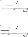
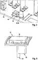
1 : ein erfindungsgemäßes Ladegerät zum Aufladen eines Wechselackupacks,2 : Diagramme eines Standard-Lademodus nach dem CCCV-Ladeverfahren und vier weiterer Lademodus nach dem CC-Ladeverfahren gemäß der Erfindung,3 : einen Detailausschnitt einer Bedieneinheit und eines Anzeigelements des Ladegeräts zum Umschalten der Lademodus und zur Anzeige des aktuellen Lademodus sowie4 : eine schematische Darstellung eines erfindungsgemäßen Betätigungsements der Bedieneinheit in einer Detailansicht.
1 a charger according to the invention for charging a removable pack,2 : Diagrams of a standard charging mode according to the CCCV charging method and four further charging modes according to the CC charging method according to the invention,3 : a detail of an operating unit and a display element of the charger to switch the charging mode and to display the current charging mode as well4 : A schematic representation of an actuating element of the control unit according to the invention in a detailed view.
Beschreibung der AusführungsbeispieleDescription of the embodiments
Zum Aufladen des Akkupacks
Mittels einer Bedieneinheit
Das Ladegerät
Der Anwender kann einen der Lademodus
Ein Zurücksetzen des Ladegeräts
Ferner kann der Anwender einen Lademodus
In
Im „Standard“-Modus
Im „Long-Life“-Modus
Der „Flight“-Modus
Über die unterschiedlichen Lademodus
Wird dagegen ein Akkupack
Vom Anwender kann über die App des externen Geräts
In den
Die Anzeige
Über die Bedienheit
Abschließend sei noch darauf hingewiesen, dass das gezeigte Ausführungsbeispiel weder auf die
ZITATE ENTHALTEN IN DER BESCHREIBUNG QUOTES INCLUDE IN THE DESCRIPTION
Diese Liste der vom Anmelder aufgeführten Dokumente wurde automatisiert erzeugt und ist ausschließlich zur besseren Information des Lesers aufgenommen. Die Liste ist nicht Bestandteil der deutschen Patent- bzw. Gebrauchsmusteranmeldung. Das DPMA übernimmt keinerlei Haftung für etwaige Fehler oder Auslassungen.This list of documents listed by the applicant has been generated automatically and is only included for the better information of the reader. The list is not part of the German patent or utility model application. The DPMA assumes no liability for any errors or omissions.
Zitierte PatentliteraturPatent literature cited
- WO 2011/018335 A2 [0005]WO 2011/018335 A2 [0005]
- WO 2012/069690 A1 [0006]WO 2012/069690 A1 [0006]
Claims (15)
Translated fromGermanPriority Applications (4)
| Application Number | Priority Date | Filing Date | Title |
|---|---|---|---|
| DE102018210524.3ADE102018210524A1 (en) | 2018-06-27 | 2018-06-27 | Process for charging battery packs for power tools and charger for carrying out the process |
| PCT/EP2019/063916WO2020001907A1 (en) | 2018-06-27 | 2019-05-29 | Method for charging battery packs for electric power tools and charger for carrying out the method |
| US17/253,403US12224612B2 (en) | 2018-06-27 | 2019-05-29 | Method for charging battery packs for power tools and charging device for carrying out the method |
| CN201980042985.5ACN112368905A (en) | 2018-06-27 | 2019-05-29 | Method for charging a battery pack for an electric power tool and charging device for carrying out the method |
Applications Claiming Priority (1)
| Application Number | Priority Date | Filing Date | Title |
|---|---|---|---|
| DE102018210524.3ADE102018210524A1 (en) | 2018-06-27 | 2018-06-27 | Process for charging battery packs for power tools and charger for carrying out the process |
Publications (1)
| Publication Number | Publication Date |
|---|---|
| DE102018210524A1true DE102018210524A1 (en) | 2020-01-02 |
Family
ID=66677146
Family Applications (1)
| Application Number | Title | Priority Date | Filing Date |
|---|---|---|---|
| DE102018210524.3APendingDE102018210524A1 (en) | 2018-06-27 | 2018-06-27 | Process for charging battery packs for power tools and charger for carrying out the process |
Country Status (4)
| Country | Link |
|---|---|
| US (1) | US12224612B2 (en) |
| CN (1) | CN112368905A (en) |
| DE (1) | DE102018210524A1 (en) |
| WO (1) | WO2020001907A1 (en) |
Cited By (4)
| Publication number | Priority date | Publication date | Assignee | Title |
|---|---|---|---|---|
| DE102021203108A1 (en) | 2021-03-29 | 2022-09-29 | Robert Bosch Gesellschaft mit beschränkter Haftung | battery pack |
| DE102022209098A1 (en) | 2022-09-01 | 2024-03-07 | Robert Bosch Gesellschaft mit beschränkter Haftung | Battery pack with a charge status display unit |
| DE102023113935A1 (en) | 2023-05-26 | 2024-11-28 | Wacker Neuson Produktion GmbH & Co. KG | Electric battery with storage mode operating state |
| DE102024109783A1 (en)* | 2024-04-09 | 2025-10-09 | Einhell Germany Ag | accumulator |
Families Citing this family (4)
| Publication number | Priority date | Publication date | Assignee | Title |
|---|---|---|---|---|
| USD1060222S1 (en)* | 2021-03-18 | 2025-02-04 | Husqvarna Ab | Battery charger |
| CN114572019A (en)* | 2022-03-16 | 2022-06-03 | 深圳市大疆创新科技有限公司 | Method for charging movable platform, base station and movable platform system |
| USD1089075S1 (en)* | 2022-04-28 | 2025-08-19 | Positec Power Tools (Suzhou) Co., Ltd. | Charger |
| EP4293860A1 (en)* | 2022-06-15 | 2023-12-20 | Braun GmbH | Personal care device with a rechargeable energy source |
Citations (4)
| Publication number | Priority date | Publication date | Assignee | Title |
|---|---|---|---|---|
| WO2011018335A2 (en) | 2009-08-11 | 2011-02-17 | Continental Automotive Gmbh | Charging device for an energy store and method for operating such a charging device |
| WO2012069690A1 (en) | 2010-11-25 | 2012-05-31 | Nokia Corporation | Context aware battery charging |
| WO2016054359A1 (en)* | 2014-10-01 | 2016-04-07 | Traxxas Lp | Battery charger with user interface |
| US20170302095A1 (en)* | 2016-04-18 | 2017-10-19 | Vitec Videocom Inc. | Smart charger with selective discharge capability |
Family Cites Families (37)
| Publication number | Priority date | Publication date | Assignee | Title |
|---|---|---|---|---|
| US3848173A (en)* | 1972-11-08 | 1974-11-12 | A Hase | Storage battery charging apparatus |
| US5463305A (en)* | 1982-06-07 | 1995-10-31 | Norand Corporation | Fast battery charging system and method |
| US4443752A (en)* | 1982-08-30 | 1984-04-17 | Utah Research & Development Co., Inc. | Solid state battery charger |
| US5172044A (en)* | 1990-02-27 | 1992-12-15 | Sony Corporation | Multi-rate constant voltage battery charger with display |
| US6100667A (en)* | 1999-01-21 | 2000-08-08 | National Semiconductor Corporation | Current-to-voltage transition control of a battery charger |
| US6333619B1 (en)* | 2000-03-15 | 2001-12-25 | Jaime H Chavez | Cyclical battery charger with incremental and decremental current and a method of operation thereof |
| US7714538B2 (en)* | 2002-11-22 | 2010-05-11 | Milwaukee Electric Tool Corporation | Battery pack |
| US20070075678A1 (en) | 2002-12-20 | 2007-04-05 | Andrew Sung On Ng | Life cycle extending batteries and battery charging means, method and apparatus |
| DE10342129A1 (en)* | 2003-09-12 | 2005-04-07 | Robert Bosch Gmbh | Charger for charging a battery and procedures for its operation |
| CN201515238U (en)* | 2004-10-18 | 2010-06-23 | 布莱克和戴克公司 | Cordless power tool system and battery pack for cordless power tool system |
| DE602006018510D1 (en)* | 2005-10-21 | 2011-01-05 | Stryker Corp | SYSTEM AND METHOD FOR RECHARGING A HARSH ENVIRONMENT EXPOSED BATTERY |
| CN201289888Y (en)* | 2007-06-20 | 2009-08-12 | 布莱克和戴克公司 | Battery group charger |
| DE102007031568A1 (en)* | 2007-07-06 | 2009-01-08 | Robert Bosch Gmbh | Device, in particular charger device, for charging a rechargeable battery |
| EP2075893B1 (en)* | 2007-10-15 | 2016-03-09 | Black & Decker, Inc. | Bottom based balancing in a lithium ion battery system |
| US9337684B2 (en)* | 2008-05-06 | 2016-05-10 | Johnson Controls Technology Company | Battery charging device and method |
| US20090289603A1 (en)* | 2008-05-21 | 2009-11-26 | Apple Inc. | Method and apparatus for maintaining a battery in a partially charged state |
| CN101404346B (en)* | 2008-11-19 | 2010-12-15 | 中国人民解放军军械工程学院 | Constant pressure impulse quick charge method |
| US8754614B2 (en)* | 2009-07-17 | 2014-06-17 | Tesla Motors, Inc. | Fast charging of battery using adjustable voltage control |
| US8706272B2 (en)* | 2009-08-14 | 2014-04-22 | Apple Inc. | Adaptive encoding and compression of audio broadcast data |
| EP2293406B1 (en)* | 2009-09-07 | 2015-08-05 | ABB Research Ltd. | Energy storage systems |
| US8643342B2 (en)* | 2009-12-31 | 2014-02-04 | Tesla Motors, Inc. | Fast charging with negative ramped current profile |
| JP5556677B2 (en)* | 2010-03-08 | 2014-07-23 | 株式会社豊田自動織機 | Battery charging circuit |
| CN102255347A (en)* | 2010-05-19 | 2011-11-23 | 日立信息能源系统有限公司 | Chariging equipment |
| JP5081326B1 (en)* | 2011-04-27 | 2012-11-28 | シャープ株式会社 | CHARGE CONTROL DEVICE, TELEVISION RECEIVER, AND CHARGE CONTROL METHOD |
| CN202260588U (en)* | 2011-07-14 | 2012-05-30 | 无锡新畅电子有限公司 | Quick charger for lithium iron phosphate battery |
| WO2013051863A2 (en)* | 2011-10-04 | 2013-04-11 | 주식회사 엘지화학 | Apparatus and method for charging a battery |
| WO2014137932A1 (en)* | 2013-03-03 | 2014-09-12 | Littelfuse, Inc. | Adaptive remote battery charging |
| JP6168148B2 (en)* | 2013-07-31 | 2017-07-26 | 日産自動車株式会社 | Solid solution lithium-containing transition metal oxide, and non-aqueous electrolyte secondary battery using the solid solution lithium-containing transition metal oxide as a positive electrode |
| GB201403971D0 (en)* | 2014-03-06 | 2014-04-23 | 7Rdd Ltd | Portable power supply improvements |
| CN108616154B (en)* | 2014-05-18 | 2021-09-14 | 百得有限公司 | Electric tool system |
| JP6599975B2 (en)* | 2014-07-28 | 2019-10-30 | イーシー パワー,エルエルシー | System and method for fast charging of batteries at low temperature |
| JP6513974B2 (en)* | 2014-11-27 | 2019-05-15 | オズマ株式会社 | Charger |
| DE102015206871A1 (en)* | 2015-04-16 | 2016-10-20 | Robert Bosch Gmbh | Energy storage system |
| US9893542B2 (en) | 2015-06-04 | 2018-02-13 | Google Llc | Systems and methods for battery charging |
| DE102016124501A1 (en)* | 2016-12-15 | 2018-06-21 | Metabowerke Gmbh | Configurable battery pack |
| CN109148985A (en)* | 2017-06-15 | 2019-01-04 | 苏州宝时得电动工具有限公司 | A kind of battery pack charging method and device |
| CN107681713B (en)* | 2017-09-13 | 2021-10-22 | 惠州Tcl移动通信有限公司 | Multi-mode charging control method, mobile terminal and storage medium |
- 2018
- 2018-06-27DEDE102018210524.3Apatent/DE102018210524A1/enactivePending
- 2019
- 2019-05-29CNCN201980042985.5Apatent/CN112368905A/enactivePending
- 2019-05-29WOPCT/EP2019/063916patent/WO2020001907A1/ennot_activeCeased
- 2019-05-29USUS17/253,403patent/US12224612B2/enactiveActive
Patent Citations (4)
| Publication number | Priority date | Publication date | Assignee | Title |
|---|---|---|---|---|
| WO2011018335A2 (en) | 2009-08-11 | 2011-02-17 | Continental Automotive Gmbh | Charging device for an energy store and method for operating such a charging device |
| WO2012069690A1 (en) | 2010-11-25 | 2012-05-31 | Nokia Corporation | Context aware battery charging |
| WO2016054359A1 (en)* | 2014-10-01 | 2016-04-07 | Traxxas Lp | Battery charger with user interface |
| US20170302095A1 (en)* | 2016-04-18 | 2017-10-19 | Vitec Videocom Inc. | Smart charger with selective discharge capability |
Non-Patent Citations (2)
| Title |
|---|
| Conrad Electronic SE: BASETech Bedienungsanleitung Multifunktionsladegerät 80 AC/DC, Best.-Nr. 1484096, Hirschau, 2016 - Firmenschrift* |
| YouTube-Video "Core SWX Fleet Battery Chargers @ NAB 2018", URL: https://www.youtube.com/watch?v=peX81PahND0, veröffentlicht am 18.04.2018 [abgerufen am 07.05.2019]* |
Cited By (4)
| Publication number | Priority date | Publication date | Assignee | Title |
|---|---|---|---|---|
| DE102021203108A1 (en) | 2021-03-29 | 2022-09-29 | Robert Bosch Gesellschaft mit beschränkter Haftung | battery pack |
| DE102022209098A1 (en) | 2022-09-01 | 2024-03-07 | Robert Bosch Gesellschaft mit beschränkter Haftung | Battery pack with a charge status display unit |
| DE102023113935A1 (en) | 2023-05-26 | 2024-11-28 | Wacker Neuson Produktion GmbH & Co. KG | Electric battery with storage mode operating state |
| DE102024109783A1 (en)* | 2024-04-09 | 2025-10-09 | Einhell Germany Ag | accumulator |
Also Published As
| Publication number | Publication date |
|---|---|
| US12224612B2 (en) | 2025-02-11 |
| WO2020001907A1 (en) | 2020-01-02 |
| CN112368905A (en) | 2021-02-12 |
| US20210273474A1 (en) | 2021-09-02 |
Similar Documents
| Publication | Publication Date | Title |
|---|---|---|
| DE102018210524A1 (en) | Process for charging battery packs for power tools and charger for carrying out the process | |
| EP3209518B1 (en) | Method for operating an energy storage device in a motor vehicle, and motor vehicle | |
| DE102018220251A1 (en) | Method and device for assessing the health status of a removable battery | |
| EP2451001B1 (en) | Mobile electric device with charge display and battery for same | |
| DE102016209822A1 (en) | Battery pack for a hand tool and / or a charger | |
| WO2018019510A1 (en) | Arrangement consisting of a motor vehicle and a connecting means, motor vehicle and connecting means | |
| DE102017200996B4 (en) | A method for determining an aging condition of an energy storage device for an electric vehicle and an electric vehicle | |
| DE102010061477A1 (en) | Method and device for controlling a drive train of a hybrid vehicle | |
| EP4016782A1 (en) | Multi-slot charger and multi-slot battery charger set | |
| DE102017123071A1 (en) | Supply of low-voltage on-board networks of vehicles with electric drive | |
| EP2977256B1 (en) | Method for controlling a lithium ion battery of an industrial truck | |
| DE102012106885A1 (en) | Traction battery such as lithium ion battery for mobile working machine e.g. fork lifting truck, has plug connector that is incorporated in coding element of power terminal for identification of type of traction battery | |
| DE102021201621A1 (en) | Electrical processing device for optional operation with at least two different supply voltages | |
| DE102021214995A1 (en) | Electrical device with a plurality of electromechanical battery interfaces | |
| DE102021210157A1 (en) | Interface module for operating an electrical consumer with at least one exchangeable energy store and method for controlling the electrical consumer using the interface module | |
| DE102021212124A1 (en) | Exchangeable energy store and method for discharging or charging an exchangeable energy store | |
| EP2760695A1 (en) | Method for operating a vehicle which can be driven with an electric motor | |
| DE202011000386U1 (en) | Energy management device | |
| DE102021201619A1 (en) | Switching device for an electric motor for selective operation with at least two different supply voltages and electrical processing device with a switching device | |
| DE102021212799A1 (en) | Method for charging or discharging a replaceable energy store using an electrical device and system with a replaceable energy store and an electrical device for carrying out the process | |
| DE102016224005A1 (en) | Electrical energy storage device | |
| EP3172791B1 (en) | Energy storage device | |
| EP3035488B1 (en) | Method and device for charging, in particular for sequential charging of rechargeable batteries and emergency charging of severely drained batteries | |
| DE102012015782B4 (en) | Method for operating a power supply unit | |
| DE102007056976A1 (en) | Battery e.g. lithium-ion battery, storage charge adjusting method for load, involves utilizing adjusting switch for adjusting storage charge of battery, discharging battery upon initial value and charging battery upon storage charge |
Legal Events
| Date | Code | Title | Description |
|---|---|---|---|
| R163 | Identified publications notified | ||
| R012 | Request for examination validly filed |