DE102018208537A1 - Device for connecting a cardiac assist system to an insertion device and method for producing a device for connecting a cardiac assist system to an insertion device - Google Patents
Device for connecting a cardiac assist system to an insertion device and method for producing a device for connecting a cardiac assist system to an insertion deviceDownload PDFInfo
- Publication number
- DE102018208537A1 DE102018208537A1DE102018208537.4ADE102018208537ADE102018208537A1DE 102018208537 A1DE102018208537 A1DE 102018208537A1DE 102018208537 ADE102018208537 ADE 102018208537ADE 102018208537 A1DE102018208537 A1DE 102018208537A1
- Authority
- DE
- Germany
- Prior art keywords
- clamping
- assist system
- cardiac assist
- cardiac
- base body
- Prior art date
- Legal status (The legal status is an assumption and is not a legal conclusion. Google has not performed a legal analysis and makes no representation as to the accuracy of the status listed.)
- Withdrawn
Links
- 230000000747cardiac effectEffects0.000titleclaimsabstractdescription114
- 238000003780insertionMethods0.000titleclaimsdescription48
- 230000037431insertionEffects0.000titleclaimsdescription48
- 238000004519manufacturing processMethods0.000titleclaimsdescription8
- 238000000034methodMethods0.000claimsdescription16
- 230000008878couplingEffects0.000claimsdescription6
- 238000010168coupling processMethods0.000claimsdescription6
- 238000005859coupling reactionMethods0.000claimsdescription6
- 230000008859changeEffects0.000claimsdescription5
- 238000004590computer programMethods0.000claimsdescription5
- 238000006073displacement reactionMethods0.000claimsdescription2
- 238000002513implantationMethods0.000description11
- 230000005540biological transmissionEffects0.000description5
- 229910001000nickel titaniumInorganic materials0.000description5
- HLXZNVUGXRDIFK-UHFFFAOYSA-Nnickel titaniumChemical compound[Ti].[Ti].[Ti].[Ti].[Ti].[Ti].[Ti].[Ti].[Ti].[Ti].[Ti].[Ni].[Ni].[Ni].[Ni].[Ni].[Ni].[Ni].[Ni].[Ni].[Ni].[Ni].[Ni].[Ni].[Ni]HLXZNVUGXRDIFK-UHFFFAOYSA-N0.000description5
- 238000013459approachMethods0.000description4
- 239000000463materialSubstances0.000description4
- 238000013461designMethods0.000description3
- 239000007943implantSubstances0.000description3
- 238000003698laser cuttingMethods0.000description3
- 238000003754machiningMethods0.000description3
- 238000004080punchingMethods0.000description3
- 230000002861ventricularEffects0.000description3
- 210000002376aorta thoracicAnatomy0.000description2
- 230000002349favourable effectEffects0.000description2
- 210000003709heart valveAnatomy0.000description2
- 230000007246mechanismEffects0.000description2
- 229920001296polysiloxanePolymers0.000description2
- 230000008569processEffects0.000description2
- 238000012545processingMethods0.000description2
- 230000002792vascularEffects0.000description2
- 208000034657ConvalescenceDiseases0.000description1
- 230000009286beneficial effectEffects0.000description1
- 230000008901benefitEffects0.000description1
- 230000017531blood circulationEffects0.000description1
- 210000004204blood vesselAnatomy0.000description1
- 230000036760body temperatureEffects0.000description1
- 238000010276constructionMethods0.000description1
- 230000001419dependent effectEffects0.000description1
- 230000000694effectsEffects0.000description1
- 239000013013elastic materialSubstances0.000description1
- 230000002496gastric effectEffects0.000description1
- 208000014674injuryDiseases0.000description1
- 238000007913intrathecal administrationMethods0.000description1
- 230000007774longtermEffects0.000description1
- 230000003287optical effectEffects0.000description1
- 238000010079rubber tappingMethods0.000description1
- 239000004065semiconductorSubstances0.000description1
- 229910001285shape-memory alloyInorganic materials0.000description1
- 229920000431shape-memory polymerPolymers0.000description1
- 238000003860storageMethods0.000description1
- 238000001356surgical procedureMethods0.000description1
- 230000009466transformationEffects0.000description1
- 230000008733traumaEffects0.000description1
Images


Classifications
- A—HUMAN NECESSITIES
- A61—MEDICAL OR VETERINARY SCIENCE; HYGIENE
- A61M—DEVICES FOR INTRODUCING MEDIA INTO, OR ONTO, THE BODY; DEVICES FOR TRANSDUCING BODY MEDIA OR FOR TAKING MEDIA FROM THE BODY; DEVICES FOR PRODUCING OR ENDING SLEEP OR STUPOR
- A61M60/00—Blood pumps; Devices for mechanical circulatory actuation; Balloon pumps for circulatory assistance
- A61M60/80—Constructional details other than related to driving
- A61M60/855—Constructional details other than related to driving of implantable pumps or pumping devices
- A61M60/861—Connections or anchorings for connecting or anchoring pumps or pumping devices to parts of the patient's body
- A—HUMAN NECESSITIES
- A61—MEDICAL OR VETERINARY SCIENCE; HYGIENE
- A61M—DEVICES FOR INTRODUCING MEDIA INTO, OR ONTO, THE BODY; DEVICES FOR TRANSDUCING BODY MEDIA OR FOR TAKING MEDIA FROM THE BODY; DEVICES FOR PRODUCING OR ENDING SLEEP OR STUPOR
- A61M60/00—Blood pumps; Devices for mechanical circulatory actuation; Balloon pumps for circulatory assistance
- A61M60/10—Location thereof with respect to the patient's body
- A61M60/122—Implantable pumps or pumping devices, i.e. the blood being pumped inside the patient's body
- A61M60/126—Implantable pumps or pumping devices, i.e. the blood being pumped inside the patient's body implantable via, into, inside, in line, branching on, or around a blood vessel
- A61M60/135—Implantable pumps or pumping devices, i.e. the blood being pumped inside the patient's body implantable via, into, inside, in line, branching on, or around a blood vessel inside a blood vessel, e.g. using grafting
- A—HUMAN NECESSITIES
- A61—MEDICAL OR VETERINARY SCIENCE; HYGIENE
- A61M—DEVICES FOR INTRODUCING MEDIA INTO, OR ONTO, THE BODY; DEVICES FOR TRANSDUCING BODY MEDIA OR FOR TAKING MEDIA FROM THE BODY; DEVICES FOR PRODUCING OR ENDING SLEEP OR STUPOR
- A61M60/00—Blood pumps; Devices for mechanical circulatory actuation; Balloon pumps for circulatory assistance
- A61M60/10—Location thereof with respect to the patient's body
- A61M60/122—Implantable pumps or pumping devices, i.e. the blood being pumped inside the patient's body
- A61M60/165—Implantable pumps or pumping devices, i.e. the blood being pumped inside the patient's body implantable in, on, or around the heart
- A61M60/178—Implantable pumps or pumping devices, i.e. the blood being pumped inside the patient's body implantable in, on, or around the heart drawing blood from a ventricle and returning the blood to the arterial system via a cannula external to the ventricle, e.g. left or right ventricular assist devices
- A—HUMAN NECESSITIES
- A61—MEDICAL OR VETERINARY SCIENCE; HYGIENE
- A61M—DEVICES FOR INTRODUCING MEDIA INTO, OR ONTO, THE BODY; DEVICES FOR TRANSDUCING BODY MEDIA OR FOR TAKING MEDIA FROM THE BODY; DEVICES FOR PRODUCING OR ENDING SLEEP OR STUPOR
- A61M60/00—Blood pumps; Devices for mechanical circulatory actuation; Balloon pumps for circulatory assistance
- A61M60/80—Constructional details other than related to driving
- A61M60/855—Constructional details other than related to driving of implantable pumps or pumping devices
- A61M60/857—Implantable blood tubes
- A61M60/859—Connections therefor
- A—HUMAN NECESSITIES
- A61—MEDICAL OR VETERINARY SCIENCE; HYGIENE
- A61M—DEVICES FOR INTRODUCING MEDIA INTO, OR ONTO, THE BODY; DEVICES FOR TRANSDUCING BODY MEDIA OR FOR TAKING MEDIA FROM THE BODY; DEVICES FOR PRODUCING OR ENDING SLEEP OR STUPOR
- A61M60/00—Blood pumps; Devices for mechanical circulatory actuation; Balloon pumps for circulatory assistance
- A61M60/80—Constructional details other than related to driving
- A61M60/855—Constructional details other than related to driving of implantable pumps or pumping devices
- A61M60/865—Devices for guiding or inserting pumps or pumping devices into the patient's body
Landscapes
- Health & Medical Sciences (AREA)
- Heart & Thoracic Surgery (AREA)
- Engineering & Computer Science (AREA)
- Cardiology (AREA)
- Life Sciences & Earth Sciences (AREA)
- Anesthesiology (AREA)
- Biomedical Technology (AREA)
- Hematology (AREA)
- Mechanical Engineering (AREA)
- Animal Behavior & Ethology (AREA)
- General Health & Medical Sciences (AREA)
- Public Health (AREA)
- Veterinary Medicine (AREA)
- Vascular Medicine (AREA)
- Transplantation (AREA)
- External Artificial Organs (AREA)
- Prostheses (AREA)
Abstract
Translated fromGermanDescription
Translated fromGermanStand der TechnikState of the art
Die Erfindung geht von einer Vorrichtung oder einem Verfahren nach Gattung der unabhängigen Ansprüche aus. Gegenstand der vorliegenden Erfindung ist auch ein Computerprogramm.The invention is based on a device or a method according to the preamble of the independent claims. The subject of the present invention is also a computer program.
Das Einbringen einer Herzklappenprothese kann mittels eines Katheterverfahrens erfolgen. Der Katheter erlaubt das Einführen, Positionieren und Freisetzen der Herzklappenprothese über einen von außen durch den Operateur gesteuerten Mechanismus. Für Herzunterstützungssysteme zur langfristigen und kurzfristigen Unterstützung, auch VAD-Systeme genannt, werden andere, invasivere Operationstechniken eingesetzt, wie beispielsweise eine Sternotomie. Systeme zur kurzfristigen Unterstützung wie beispielsweise Impellapumpen werden ohne spezielle Katheter implantiert.The insertion of a heart valve prosthesis can be done by means of a catheter method. The catheter allows insertion, positioning and release of the prosthetic heart valve via an externally controlled by the surgeon mechanism. Cardiac support systems for long-term and short-term support, also known as VAD systems, use other, more invasive surgical techniques, such as a sternotomy. Short-term support systems such as impeller pumps are implanted without special catheters.
Offenbarung der ErfindungDisclosure of the invention
Vor diesem Hintergrund werden mit dem hier vorgestellten Ansatz eine Vorrichtung zum Anbinden eines Herzunterstützungssystems an eine Einführeinrichtung und ein Verfahren zum Herstellen einer Vorrichtung zum Anbinden eines Herzunterstützungssystems an eine Einführeinrichtung und eine Herstellvorrichtung, das dieses Verfahren verwendet, sowie schließlich ein entsprechendes Computerprogramm gemäß den Hauptansprüchen vorgestellt. Durch die in den abhängigen Ansprüchen aufgeführten Maßnahmen sind vorteilhafte Weiterbildungen und Verbesserungen der im unabhängigen Anspruch angegebenen Vorrichtung möglich.Against this background, with the approach presented here, a device for connecting a cardiac assisting system to an insertion device and a method for producing a device for connecting a cardiac assisting system to an insertion device and a manufacturing device using this method, and finally a corresponding computer program according to the main claims are presented , The measures listed in the dependent claims advantageous refinements and improvements of the independent claim device are possible.
Mit dem hier vorgestellten Ansatz kann ein Herzunterstützungssystem, auch ventrikuläres Unterstützungssysteme oder VAD genannt, lösbar an eine Einführeinrichtung gekoppelt werden, um das Herzunterstützungssystem beispielsweise minimalinvasiv in einen Körper einbringen zu können. Dazu koppelt eine Vorrichtung das zu implantierende Herzunterstützungssystem mit einer wieder lösbaren Klammereinrichtung sicher mit der Einführeinrichtung, was ein gesteuertes und zielgerichtetes Einbringen des Herzunterstützungssystems, das dazu beispielsweise in einen Katheter geschoben werden kann, ermöglicht. Am Bestimmungsort kann die Anbindung des Herzunterstützungssystems an die Einführeinrichtung durch die Vorrichtung gelöst werden, wodurch ein gezieltes Freisetzen des Herzunterstützungssystems ermöglicht wird. Die Vorrichtung bleibt dabei an die Einführeinrichtung gekoppelt und kann auf diese Weise nach dem Freisetzen des Herzunterstützungssystems zusammen mit der Einführeinrichtung entfernt werden.With the approach presented here, a cardiac support system, also called a ventricular assist device or VAD, can be detachably coupled to an insertion device in order to be able to introduce the cardiac support system into a body in a minimally invasive manner, for example. For this purpose, a device securely couples the cardiac assist system to be implanted with a releasable stapling device to the insertion device, which allows a controlled and targeted introduction of the cardiac assisting system, which can be pushed into a catheter, for example. At the destination, the connection of the cardiac assist system to the insertion device can be solved by the device, whereby a targeted release of the cardiac assistance system is made possible. The device remains coupled to the introducer and can be removed in this way after releasing the cardiac assist system together with the introducer.
Es wird eine Vorrichtung zum Anbinden eines Herzunterstützungssystems an eine Einführeinrichtung vorgestellt. Die Vorrichtung ist dazu ausgeformt, das Herzunterstützungssystem lösbar mit der Einführeinrichtung zu koppeln. Die Vorrichtung weist zumindest einen Grundkörper, insbesondere einen rohrförmigen Grundkörper und eine Klammereinrichtung mit zumindest einem Klemmflügel auf. Die Klammereinrichtung ist dazu ausgebildet, das Herzunterstützungssystem in einem Anbindungszustand mechanisch mit der Einführeinrichtung zu koppeln. Zudem ist die Klammereinrichtung dazu ausgebildet, das Herzunterstützungssystem in einem Freisetzungszustand durch eine Dislokation und/oder ein Aufklappen des zumindest einen Klemmflügels von der Einführeinrichtung zu lösen.A device for connecting a cardiac assist system to an introducer is presented. The device is configured to releasably couple the cardiac assist system to the introducer. The device has at least one base body, in particular a tubular base body and a clamping device with at least one clamping wing. The stapler is adapted to mechanically couple the cardiac assist system to the introducer in a tethered condition. In addition, the clamping device is designed to release the cardiac assist system in a release state by dislocation and / or unfolding of the at least one clamping wing from the insertion device.
Die Vorrichtung kann aus einem elastischen Material realisiert werden, das gleichzeitig eine bestimmte Steifigkeit aufweist, beispielsweise aus Nitinol. Die Vorrichtung kann beispielsweise über einen Formschluss und/oder über einen Kraftschluss an das Gehäuse des Herzunterstützungssystems und an die Einführeinrichtung gekoppelt werden. Sie kann beispielsweise als Verbindungselement realisiert sein, wobei das Herzunterstützungssystem an ein Endabschnitt der Vorrichtung und die Einführeinrichtung an einen anderen Endabschnitt der Vorrichtung gekoppelt werden kann. Um den Anbindungszustand herbeizuführen, kann der zumindest eine Klemmflügel beispielsweise formschlüssig in ein Verbindungselement am Gehäuse des Herzunterstützungssystems eingreifen, und die Einführeinrichtung kann beispielsweise an den Grundkörper der Vorrichtung gekoppelt werden. Im Freisetzungszustand kann durch das Aufklappen des zumindest einen Klemmflügels das Herzunterstützungssystem von der Vorrichtung und damit von der Einführeinrichtung gelöst werden. Die Vorrichtung kann im Freisetzungszustand weiterhin an die Einführeinrichtung gekoppelt bleiben, beispielsweise um die Vorrichtung nach erfolgtem Freisetzen des Herzunterstützungssystems am Bestimmungsort zusammen mit der Einführeinrichtung wieder aus dem Körper entfernen zu können.The device can be realized from an elastic material which at the same time has a certain stiffness, for example from nitinol. The device can be coupled to the housing of the cardiac assistance system and to the insertion device, for example, via a positive connection and / or via a positive connection. It may for example be realized as a connecting element, wherein the cardiac assist system can be coupled to one end portion of the device and the insertion device to another end portion of the device. In order to bring about the connection state, the at least one clamping wing can, for example, engage positively in a connecting element on the housing of the cardiac support system, and the insertion device can be coupled, for example, to the main body of the device. In the release state can be solved by the unfolding of the at least one clamping wing, the cardiac assist system of the device and thus of the insertion device. In the release state, the device can continue to remain coupled to the insertion device, for example in order to be able to remove the device from the body once the cardiac assisting system has been released at the destination together with the insertion device.
Bei dem Herzunterstützungssystem kann es sich beispielsweise um ein rechtsventrikuläres Unterstützungssystem, ein linksventrikuläres Unterstützungssystem, ein biventrikuläres Unterstützungssystem oder um eine Gefäß- oder Klappenprothese handeln. Zudem kann die Vorrichtung auch verwendet werden, um ein anderes vaskuläres oder intrakavitäres Implantat wie beispielsweise ein gastrointestinales, intrathekales, oder intravesikales Implantat, lösbar mit der Einführeinrichtung zu koppeln, um das entsprechende Implantat über die Vorrichtung an den Bestimmungsort zu führen und dort freisetzen zu können. Die Einführeinrichtung kann beispielsweise als medizinisches oder chirurgisches Instrument verwendet werden und einen Katheter umfassen und/oder zumindest abschnittsweise in einen Katheter einführbar sein. Mittels der Vorrichtung ist es vorteilhafterweise möglich, das Herzunterstützungssystem minimalinvasiv einzubringen. Die minimalinvasive Einbringung kann das Trauma einer Operation senken und beschleunigt die Rekonvaleszenz. Da die Implantation von Herzunterstützungssystemen kurzzeitig ohne Katheter erfolgen kann, kann eine gezielte Positionierung des Herzunterstützungssystems durch den Operateur erschwert sein. Vorteilhafterweise ermöglicht die hier vorgestellte Vorrichtung ein wieder lösbares Anbinden des Herzunterstützungssystems an die Einführeinrichtung, was vorteilhafterweise eine gesteuerte und zielgerichtete Implantation und Freisetzung des Herzunterstützungssystems am Bestimmungsort erleichtern kann.The cardiac assist system may be, for example, a right ventricular assist device, a left ventricular assist system, a biventricular assist system, or a vascular or valve prosthesis. In addition, the device may also be used to releasably couple another vascular or intracavitary implant, such as a gastrointestinal, intrathecal, or intravesical implant, to the introducer to guide and release the appropriate implant through the device to the destination site , The introducer can be used, for example, as a medical or surgical instrument be used and include a catheter and / or at least partially be inserted into a catheter. By means of the device it is advantageously possible to introduce the cardiac support system in a minimally invasive manner. The minimally invasive introduction can reduce the trauma of an operation and accelerate convalescence. Since the implantation of cardiac support systems can be carried out for a short time without a catheter, a targeted positioning of the cardiac support system by the surgeon can be difficult. Advantageously, the device presented here allows a detachable connection of the cardiac assist system to the insertion device, which can advantageously facilitate a controlled and targeted implantation and release of the cardiac support system at the destination.
Der zumindest eine Klemmflügel der Klammereinrichtung kann gemäß einer vorteilhaften Ausführungsform als ein Formgedächtniselement ausgeformt sein. Dazu kann der Klemmflügel beispielsweise aus einem Formgedächtnispolymer oder einer Formgedächtnislegierung ausgeformt sein, vorzugsweise aus Nitinol. Die Realisierung des zumindest einen Klemmflügel als Formgedächtniselement, beispielsweise aus Nitinol, ist besonders hinsichtlich des Aufklappens des zumindest einen Klemmflügel im Freisetzungszustand der Klammereinrichtung vorteilhaft, der zumindest eine Klemmflügel kann sich beispielsweise im Anbindungszustand in einem vorgespannten Zustand befinden, und für den Freisetzungszustand zum Aufklappen seinen Ursprungszustand, die ursprünglich eingeprägte Grundform, wieder annehmen. Zusätzlich zum zumindest einen Klemmflügel können beispielsweise auch die Klammereinrichtung oder die gesamte Vorrichtung als Formgedächtniselement ausgeformt sein.The at least one clamping wing of the clamping device can be formed according to an advantageous embodiment as a shape memory element. For this purpose, the clamping wing may for example be formed from a shape memory polymer or a shape memory alloy, preferably nitinol. The realization of the at least one clamping wing as a shape memory element, for example of Nitinol, is particularly advantageous in terms of unfolding the at least one clamping wing in the release state of the stapler, the at least one clamping wing can be in a state of prestressing in a prestressed state, and for the release state for unfolding his Original state, the originally embossed basic form, again accept. In addition to the at least one clamping wing, for example, the stapling device or the entire device can be formed as a shape memory element.
Zudem kann der zumindest eine Klemmflügel gemäß einer Ausführungsform zumindest ein in einen Endabschnitt eines Herzunterstützungssystems formschlüssig eingreifbares oder eingreifendes Element und/oder zumindest eine Aussparung zum formschlüssigen Aufnehmen eines Elements zum mechanischen Koppeln des Herzunterstützungssystems mit der Vorrichtung aufweisen. Die Aussparung und/oder das Element können beispielsweise zentral des Klemmflügels positioniert sein, um das Herzunterstützungssystem besonders stabil zu fixieren. Das Element und die Aussparung können verschiedene Formen aufweisen, sie können beispielsweise eine kreisförmige, ovale, drei- oder vieleckige oder sternförmige Form aufweise, zudem kann der Querschnitt des Elements beispielsweise ein Rechteck, eine Abflachung, eine Abrundung, einen Halbkreis oder einen Hinterschnitt aufweisen. Die Elemente können beispielsweise einen Durchmesser von 1,5 Millimeter und eine Höhe von 0,5 Millimeter aufweisen. Wenn der Klemmflügel beispielsweise nur eine Aussparung für ein sich am Gehäuse des Herzunterstützungssystems befindliches Element aufweist, kann die Höhe der Aussparung beispielsweise der Wandstärke des Klemmflügels entsprechen.In addition, according to one embodiment, the at least one clamping wing may have at least one element which can be positively engaged or engaged in an end section of a cardiac support system and / or at least one recess for the positive reception of an element for mechanically coupling the cardiac assist system to the device. The recess and / or the element may, for example, be positioned centrally of the clamping wing in order to fix the cardiac support system in a particularly stable manner. The element and the recess may have different shapes, they may, for example, a circular, oval, triangular or polygonal or star-shaped form, also the cross section of the element may for example have a rectangle, a flattening, a rounding, a semicircle or an undercut. The elements may, for example, have a diameter of 1.5 millimeters and a height of 0.5 millimeters. For example, if the clamping wing has only one recess for a member located on the housing of the cardiac assist system, the height of the recess may correspond to, for example, the wall thickness of the clamping wing.
Für das stabile Anbinden des Herzunterstützungssystems an die Vorrichtung und damit an die Einführeinrichtung kann es zudem vorteilhaft sein, wenn die Klammereinrichtung gemäß einer Ausführungsform zwei Klemmflügel aufweist, insbesondere wobei die zumindest zwei Klemmflügel (beispielsweise beidseitig) gleichmäßig beabstandet angeordnet sind. Die Klammereinrichtung kann beispielsweise auch mehrere Klemmflügel, beispielsweise drei Klemmflügel, aufweisen, insbesondere wobei diese Klemmflügel einen gleichen Abstand zueinander aufweisen. Diese Ausführungsform mit zumindest zwei Klemmflügeln kann hinsichtlich des Anbindungszustandes in Bezug auf eine besonders stabile Fixierung des Herzunterstützungssystems vorteilhaft sein. Zudem kann sie hinsichtlich des Freisetzungszustands des Herzunterstützungssystems vorteilhaft sein, insbesondere wenn die zumindest zwei Klemmflügel beidseitig gleichmäßig beabstandet angeordnet sind, um die Position des am Bestimmungsort befindlichen Herzunterstützungssystems durch ein gleichmäßiges Aufklappen der Klemmflügel nicht durch das Freisetzen zu verändern.For the stable attachment of the cardiac assist system to the device and thus to the insertion device, it may also be advantageous if the clip device according to one embodiment has two clamping wings, in particular wherein the at least two clamping wings (for example, on both sides) are arranged uniformly spaced. The clamping device can, for example, also have a plurality of clamping wings, for example three clamping wings, in particular, wherein these clamping wings are equidistant from one another. This embodiment with at least two clamping wings may be advantageous in terms of the connection state with respect to a particularly stable fixation of the cardiac assist system. In addition, it may be advantageous in terms of the release state of the cardiac support system, in particular if the at least two clamping wings are arranged evenly spaced on both sides in order not to change the position of the cardiac support system located at the destination by a uniform opening of the clamping wings by the release.
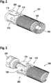
Die Vorrichtung kann gemäß einer Ausführungsform zusätzlich eine Hülse aufweisen, wobei die Hülse dazu ausgeformt ist, die Vorrichtung im Anbindungszustand der Klammereinrichtung zu umschließen. Der Anbindungszustand des Herzunterstützungssystems an die Vorrichtung kann beispielsweise erfolgen, indem der zumindest eine Klemmflügel axial über das speziell gestaltete Gehäuse des Herzunterstützungssystems geschoben wird. Das Gehäuse des Herzunterstützungssystems kann dazu beispielsweise ein formschlüssiges Element oder Aussparungen zum Aufnehmen eines formschlüssigen Elements des zumindest einen Klemmflügels gemäß einer Ausführungsform aufweisen. Nach dem Abklappen des Klemmflügels kann beispielsweise die Hülse über die Vorrichtung, die beispielsweise flexibel und biegsam ausgeführt sein kann, geführt werden. Der Klemmflügel kann nun beispielsweise von der Hülse niedergehalten werden, und das Herzunterstützungssystem kann beispielsweise im Anbindungszustand in einen Katheter eingebracht werden, der für die Implantation des Herzunterstützungssystems in den Blutkreislauf eingeführt werden kann. Dabei ist eine axiale und rotatorische Kraftübertragung auf das Herzunterstützungssystem zur Steuerung von außen möglich. Die Anbindung kann derart ausgeführt sein, dass die Vorrichtung sicher über die Hülse durch eine Radialkraft festgehalten und mit dem Gehäuse des Herzunterstützungssystems verbunden bleiben kann. Dies kann von Vorteil sein, da bei der Implantation auf diese Weise sowohl Vorwärts- und Rückwärtsbewegungen ohne Auswirkung auf die Verbindung durchgeführt werden können.The device may additionally comprise a sleeve according to an embodiment, wherein the sleeve is formed to enclose the device in the connected state of the stapling device. The connection state of the cardiac assistance system to the device can be effected, for example, by pushing the at least one clamping wing axially over the specially designed housing of the cardiac support system. For this purpose, the housing of the cardiac assisting system may, for example, have a positive-locking element or recesses for receiving a positive-locking element of the at least one clamping wing according to an embodiment. After folding down the clamping wing, for example, the sleeve can be guided over the device, which can be flexible and flexible, for example. The clamping wing can now be held down by the sleeve, for example, and the cardiac support system can be introduced, for example in the connected state, into a catheter which can be introduced into the blood circulation for the implantation of the cardiac support system. In this case, an axial and rotary power transmission to the cardiac assist system for external control is possible. The connection can be made such that the device can be securely held over the sleeve by a radial force and remain connected to the housing of the cardiac assist system. This can be beneficial because both in implantation in this way Forward and backward movements can be performed without affecting the connection.
Wenn die Vorrichtung gemäß einer Ausführungsform die Hülse aufweist, kann die Klammereinrichtung dazu ausgebildet sein, bei einem Entfernen oder Verschieben der Hülse vom Anbindungszustand in den Freisetzungszustand überführt zu werden. Der Freisetzungszustand kann vorteilhafterweise besonders einfach durch ein Zurückziehen der Hülse, die den Klemmflügel niederhält, erfolgen. Der Klemmflügel kann durch das Zurückziehen der Hülse beispielsweise von einem vorgespannten Zustand in den Ursprungszustand aufklappen. Wenn der Klemmflügel gemäß einer Ausführungsform beispielsweise als Formgedächtniselement ausgeformt ist, kann der Freisetzungszustand mittels einer unterhalb der menschlichen Körpertemperatur liegenden Transformationstemperatur herbeigeführt werden. Alternativ kann der Freisetzungszustand beispielsweise auch aktiv durch einen definierten Impuls, beispielsweise einem elektrisch ansteuerbaren Mechanismus, herbeigeführt werden. Dies kann alternativ oder zusätzlich zum Aufklappen des Klemmflügels durch ein Zurückziehen der Hülse erfolgen.According to one embodiment, when the device comprises the sleeve, the clamping device can be designed to be transferred from the connection state to the release state upon removal or displacement of the sleeve. The release state can be advantageously particularly simple by retracting the sleeve which holds down the clamping wing. The clamping wing can unfold by retracting the sleeve, for example, from a prestressed state to the original state. For example, if the clamping wing according to an embodiment is shaped as a shape memory element, the release state can be brought about by means of a transformation temperature below the human body temperature. Alternatively, the release state, for example, actively by a defined pulse, for example, an electrically controllable mechanism, be brought about. This can be done alternatively or in addition to unfolding the clamping wing by pulling back the sleeve.
Gemäß einer weiteren Ausführungsform kann die Klammereinrichtung einen Steg aufweisen, wobei der Steg dazu ausgeformt ist, einen Hals zwischen dem Grundkörper und dem zumindest einen Klemmflügel zu bilden, insbesondere wobei der Steg eine geringere Breite als der Klemmflügel aufweist. Der Steg kann beispielsweise zwischen dem Grundkörper und dem zumindest einen Klemmflügel als Verbindung zwischen dem Klemmflügel und dem Grundkörper realisiert sein. Der Steg kann vorteilhafterweise so ausgeführt sein, dass die Kraft zum Öffnen und Schließen der Klammereinrichtung durch eine Auf- und Abklappen des Klemmflügels für die Implantation geeignet ist. Die Wandstärke des Stegs kann beispielsweise der Wandstärke des Grundkörpers und/oder des Klemmflügels entsprechen. Der Steg kann beispielsweise in Bezug auf die Umfangrichtung und den Umfang des Grundkörpers eine geringere Breite aufweisen. Die Querschnittsfläche des Stegs kann beispielsweise ein Drittel der Querschnittsfläche des Klemmflügels betragen. Der Steg kann zudem beispielsweise zum Verändern der Steifigkeit eine Aussparung aufweisen. Wenn die Klammereinrichtung gemäß einer Ausführungsform beispielsweise mehrere Klemmflügel umfasst, kann die Klammereinrichtung für jeden Klemmflügel einen Steg aufweisen.According to a further embodiment, the clamping means may comprise a web, wherein the web is formed to form a neck between the base body and the at least one clamping wing, in particular wherein the web has a smaller width than the clamping wing. The web can be realized, for example, between the base body and the at least one clamping wing as a connection between the clamping wing and the base body. The web can advantageously be designed so that the force for opening and closing the stapling device by folding up and down the clamping wing is suitable for implantation. The wall thickness of the web, for example, the wall thickness of the body and / or the clamping wing correspond. The web may, for example, have a smaller width with respect to the circumferential direction and the circumference of the main body. The cross-sectional area of the web can be, for example, one third of the cross-sectional area of the clamping wing. The web can also have a recess, for example, for changing the rigidity. For example, in one embodiment, when the stapling device includes a plurality of clamping wings, the stapling device may comprise a web for each clamping wing.
Vorteilhafterweise kann die Vorrichtung gemäß einer Ausführungsform einstückig ausgeformt sein. Die Vorrichtung kann aus einem Material, beispielsweise aus einem Rohr gefertigt werden. Dies ist für eine kompakte Bauweise von Vorteil, da die Vorrichtung als einstückige Ausführung wenig Bauraum benötigt. Die Vorrichtung kann beispielsweise aus einem Rohr freigeschnitten werden und der zumindest eine Klemmflügel kann beispielsweise mit Hilfe von Stanzverfahren, Laser-Schneiden oder einer spanenden Bearbeitung realisiert werden. Wenn die Vorrichtung gemäß einer Ausführungsform zudem Aussparungen im Klemmflügel und/oder eine Steg aufweist, können diese durch eine Materialwegnahme mittels einer der genannten Bearbeitungsformen ausgeformt werden.Advantageously, the device according to one embodiment may be integrally formed. The device can be made of a material, for example of a tube. This is advantageous for a compact construction, since the device requires little space as a one-piece design. The device can for example be cut free from a tube and the at least one clamping wing can be realized for example by means of punching, laser cutting or machining. If, according to one embodiment, the device also has recesses in the clamping wing and / or a web, these can be formed by a material removal by means of one of the mentioned processing forms.
Der rohrförmige Grundkörper der Vorrichtung kann gemäß einer Ausführungsform als Hohlzylinder ausgeformt sein, insbesondere zum Aufnehmen eines flexiblen Schlauchs. Die Ausformung als Hohlzylinder kann in Bezug auf die Steifigkeit und Festigkeit der Vorrichtung vorteilhaft sein, da der Grundkörper zur Kraft- und Momentübertragung von der Einführeinrichtung über die Vorrichtung auf das Herzunterstützungssystem dienen kann. Dazu kann das Gewährleisten einer gewissen Steifigkeit und Festigkeit sowohl in axialer als auch in rotatorischer Richtung vorteilhaft sein. Zudem kann die Vorrichtung durch die Ausformung als Hohlzylinder einen flexiblen Schlauch aufnehmen, beispielsweise einen Silikonschlauch, um durch die Schlauchaufnahmen die Flexibilität der Vorrichtung sowie die Festigkeitseigenschaften der Vorrichtung zu verändern.The tubular body of the device can be formed according to an embodiment as a hollow cylinder, in particular for receiving a flexible hose. The configuration as a hollow cylinder may be advantageous in terms of the rigidity and strength of the device, since the base body can serve for transmitting force and torque from the insertion device via the device to the cardiac assist system. This can be advantageous to ensure a certain rigidity and strength both in the axial and in the rotational direction. In addition, the device can take the form of a hollow cylinder, a flexible hose, for example, a silicone hose to change the flexibility of the device and the strength properties of the device through the tube receptacles.
Zudem kann der Grundkörper gemäß einer Ausführungsform zumindest eine Steifigkeitsaussparung aufweisen. Die zumindest eine Steifigkeitsaussparung ist dazu ausgeformt, die Steifigkeit des Grundkörpers zu verändern. Die Steifigkeitsaussparung kann von Vorteil sein, um bei einer bestimmten Flexibilität des Grundkörpers noch ausreichend Steifigkeit für die Kraftübertragung zu erhalten. Die bestimmte Flexibilität des Grundkörpers und damit der Vorrichtung kann vorteilhaft sein, um beispielsweise eine Implantation über den Aortenbogen ermöglichen zu können. Die Steifigkeitsaussparung kann beispielsweise spiralförmig realisiert sein. Der Grundkörper kann für eine vorteilhafte Flexibilität insbesondere eine Mehrzahl an Steifigkeitsaussparung über zumindest die Hälfte der Länge des Grundkörpers aufweisen.In addition, according to one embodiment, the main body can have at least one stiffness recess. The at least one stiffness recess is designed to change the rigidity of the body. The stiffness recess may be advantageous in order to obtain sufficient rigidity for the power transmission with a certain flexibility of the base body. The particular flexibility of the base body and thus of the device can be advantageous in order to enable, for example, implantation via the aortic arch. The stiffness recess can be realized, for example, spirally. For a favorable flexibility, the main body may in particular have a plurality of stiffness recesses over at least half the length of the main body.
Die Klammereinrichtung kann gemäß einer Ausführungsform an einem Endabschnitt des Grundkörpers angeordnet sein, und der Grundkörper kann an einem der Klammereinrichtung gegenüberliegenden anderen Endabschnitt zumindest eine Anbindeaussparung zum Anbinden der Einführeinrichtung aufweisen. Diese Ausführungsform ermöglicht vorteilhafterweise, die Vorrichtung als Verbindungselement zwischen dem Herzunterstützungssystem auf Seiten der Klammereinrichtung und der Einführeinrichtung auf der gegenüberliegenden Seite zu verwenden, was eine besonders platzsparende und einfach zu realisierende Anbindungsmöglichkeit darstellt. Vorteilhafterweise kann die Vorrichtung zudem ausgeformt sein, um in Verbindung mit verschiedenen Herzunterstützungssystemen und verschiedenen Einführeinrichtungen verwendet zu werden, beispielsweise durch eine Variation von Aussparungen zum Anbinden des Herzunterstützungssystems und/oder der Einführeinrichtung.According to one embodiment, the clamping device can be arranged on an end section of the main body, and the main body can have at least one tapping recess for tying the insertion device on an other end section opposite the clamping device. This embodiment advantageously makes it possible to use the device as a connecting element between the cardiac support system on the side of the stapling device and the insertion device on the opposite side, which is a particularly space-saving and easy to implement connection possibility represents. Advantageously, the device may also be shaped to be used in conjunction with various cardiac assist systems and various introducers, for example by a variation of recesses for engaging the cardiac assist system and / or the introducer.
Gemäß einer weiteren vorteilhaften Ausführungsform kann die Vorrichtung eine Länge von weniger als 50 Millimeter aufweisen, insbesondere von weniger als 40 Millimeter. Zusätzlich oder alternativ kann der zumindest eine Klemmflügel im Freisetzungszustand um mindestens 0,5 Millimeter aufklappbar sein. Diese Ausführungsform kann in Bezug auf die Verwendung der Vorrichtung im Zusammenhang mit minimalinvasiven Implantationsverfahren vorteilhaft sein, durch eine geringe starre Länge der Verbindung des Herzunterstützungssystems mit der Vorrichtung, insbesondere, um eine Implantation über den Aortenbogen zu ermöglichen.According to a further advantageous embodiment, the device may have a length of less than 50 millimeters, in particular less than 40 millimeters. Additionally or alternatively, the at least one clamping wing in the release state can be hinged by at least 0.5 millimeters. This embodiment may be advantageous in relation to the use of the device in connection with minimally invasive implantation procedures, by a small rigid length of connection of the cardiac assist system to the device, in particular to allow implantation over the aortic arch.
Es wird ferner ein Verfahren zum Herstellen der Vorrichtung gemäß einer Ausführungsform vorgestellt. Das Verfahren weist umfasst zumindest einen Schritt des Ausbildens eines rohrförmigen Grundkörpers und einer Klammereinrichtung mit zumindest einem Klemmflügel, um die Vorrichtung herzustellen. Die Klammereinrichtung ist dazu ausgebildet, ein Herzunterstützungssystem in einem Anbindungszustand mechanisch mit einer Einführeinrichtung zu koppeln und das Herzunterstützungssystem in einem Freisetzungszustand durch ein Aufklappen des zumindest einen Klemmflügels von der Einführeinrichtung zu lösen.There is further provided a method of manufacturing the device according to an embodiment. The method comprises at least one step of forming a tubular base body and a clamping device with at least one clamping wing in order to produce the device. The stapler is adapted to mechanically couple a cardiac assist system in an attachment state to an insertion device and to disengage the cardiac assist system in a release state by unfolding the at least one cam follower from the insertion device.
Dieses Verfahren kann beispielsweise in Software oder Hardware oder in einer Mischform aus Software und Hardware beispielsweise in einem Steuergerät implementiert sein.This method can be implemented, for example, in software or hardware or in a mixed form of software and hardware, for example in a control unit.
Der hier vorgestellte Ansatz schafft ferner eine Herstellvorrichtung, die ausgebildet ist, um den Schritt des hier vorgestellten Verfahrens in entsprechenden Einrichtungen durchzuführen, anzusteuern bzw. umzusetzen.The approach presented here also creates a manufacturing device that is designed to perform the step of the method presented here in appropriate facilities to drive or implement.
Von Vorteil ist auch ein Computerprogrammprodukt oder Computerprogramm mit Programmcode, der auf einem maschinenlesbaren Träger oder Speichermedium wie einem Halbleiterspeicher, einem Festplattenspeicher oder einem optischen Speicher gespeichert sein kann und zur Durchführung, Umsetzung und/oder Ansteuerung des Schritts des Verfahrens nach der vorstehend beschriebenen Ausführungsform verwendet wird, insbesondere wenn das Programmprodukt oder Programm auf einem Computer oder einer Herstellvorrichtung ausgeführt wird.Also of advantage is a computer program product or computer program with program code which can be stored on a machine-readable carrier or storage medium such as a semiconductor memory, a hard disk memory or an optical memory and used for carrying out, implementing and / or driving the step of the method according to the embodiment described above especially when the program product or program is executed on a computer or manufacturing device.
Ausführungsbeispiele des hier vorgestellten Ansatzes sind in den Zeichnungen dargestellt und in der nachfolgenden Beschreibung näher erläutert. Es zeigt:
1 eine schematische Darstellung einer Vorrichtung zum Anbinden eines Herzunterstützungssystems an eine Einführeinrichtung gemäß einem Ausführungsbeispiel;2 eine schematische Darstellung einer Vorrichtung zum Anbinden eines Herzunterstützungssystems an eine Einführeinrichtung gemäß einem Ausführungsbeispiel;3 eine schematische Darstellung einer Vorrichtung zum Anbinden eines Herzunterstützungssystems an eine Einführeinrichtung gemäß einem Ausführungsbeispiel;4a bis4c je eine schematische Darstellung eines Teils einer Vorrichtung zum Anbinden eines Herzunterstützungssystems an eine Einführeinrichtung gemäß einem Ausführungsbeispiel;5 eine schematische Darstellung eines Teils einer Vorrichtung zum Anbinden eines Herzunterstützungssystems an eine Einführeinrichtung gemäß einem Ausführungsbeispiel;6 eine schematische Darstellung einer Vorrichtung zum Anbinden eines Herzunterstützungssystems an eine Einführeinrichtung gemäß einem Ausführungsbeispiel; und7 ein Ablaufdiagramm eines Verfahrens zum Herstellen einer Vorrichtung zum Anbinden eines Herzunterstützungssystems an eine Einführeinrichtung gemäß einem Ausführungsbeispiel.
1 a schematic representation of an apparatus for connecting a cardiac assist system to an insertion device according to an embodiment;2 a schematic representation of an apparatus for connecting a cardiac assist system to an insertion device according to an embodiment;3 a schematic representation of an apparatus for connecting a cardiac assist system to an insertion device according to an embodiment;4a to4c each a schematic representation of a part of a device for connecting a cardiac assist system to an insertion device according to an embodiment;5 a schematic representation of a portion of a device for connecting a cardiac assist system to an insertion device according to an embodiment;6 a schematic representation of an apparatus for connecting a cardiac assist system to an insertion device according to an embodiment; and7 a flowchart of a method for producing a device for connecting a cardiac assist system to an insertion device according to an embodiment.
In der nachfolgenden Beschreibung günstiger Ausführungsbeispiele der vorliegenden Erfindung werden für die in den verschiedenen Figuren dargestellten und ähnlich wirkenden Elemente gleiche oder ähnliche Bezugszeichen verwendet, wobei auf eine wiederholte Beschreibung dieser Elemente verzichtet wird.In the following description of favorable embodiments of the present invention, the same or similar reference numerals are used for the elements shown in the various figures and similar acting, with a repeated description of these elements is omitted.
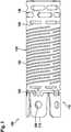
Die Klemmflügel
Die Klammereinrichtung
Die Vorrichtung
Die Vorrichtung
Gemäß dem hier gezeigten Ausführungsbeispiel weist der Grundkörper
Die Klammereinrichtung
Die Vorrichtung
Umfasst ein Ausführungsbeispiel eine „und/oder“-Verknüpfung zwischen einem ersten Merkmal und einem zweiten Merkmal, so ist dies so zu lesen, dass das Ausführungsbeispiel gemäß einer Ausführungsform sowohl das erste Merkmal als auch das zweite Merkmal und gemäß einer weiteren Ausführungsform entweder nur das erste Merkmal oder nur das zweite Merkmal aufweist.If an exemplary embodiment comprises a "and / or" link between a first feature and a second feature, then this is to be read so that the embodiment according to one embodiment, both the first feature and the second feature and according to another embodiment either only first feature or only the second feature.
Claims (15)
Translated fromGermanPriority Applications (4)
| Application Number | Priority Date | Filing Date | Title |
|---|---|---|---|
| DE102018208537.4ADE102018208537A1 (en) | 2018-05-30 | 2018-05-30 | Device for connecting a cardiac assist system to an insertion device and method for producing a device for connecting a cardiac assist system to an insertion device |
| PCT/EP2019/064130WO2019229207A1 (en) | 2018-05-30 | 2019-05-30 | Device for attaching a heart support system to an insertion device, and method for producing same |
| US17/057,045US20210290939A1 (en) | 2018-05-30 | 2019-05-30 | Device for attaching a heart support system to an insertion device, and method for producing same |
| DE112019002707.7TDE112019002707A5 (en) | 2018-05-30 | 2019-05-30 | DEVICE FOR CONNECTING A SUPPORT SYSTEM TO AN IMPLEMENTATION DEVICE AND METHOD FOR MANUFACTURING IT |
Applications Claiming Priority (1)
| Application Number | Priority Date | Filing Date | Title |
|---|---|---|---|
| DE102018208537.4ADE102018208537A1 (en) | 2018-05-30 | 2018-05-30 | Device for connecting a cardiac assist system to an insertion device and method for producing a device for connecting a cardiac assist system to an insertion device |
Publications (1)
| Publication Number | Publication Date |
|---|---|
| DE102018208537A1true DE102018208537A1 (en) | 2019-12-05 |
Family
ID=66793955
Family Applications (2)
| Application Number | Title | Priority Date | Filing Date |
|---|---|---|---|
| DE102018208537.4AWithdrawnDE102018208537A1 (en) | 2018-05-30 | 2018-05-30 | Device for connecting a cardiac assist system to an insertion device and method for producing a device for connecting a cardiac assist system to an insertion device |
| DE112019002707.7TPendingDE112019002707A5 (en) | 2018-05-30 | 2019-05-30 | DEVICE FOR CONNECTING A SUPPORT SYSTEM TO AN IMPLEMENTATION DEVICE AND METHOD FOR MANUFACTURING IT |
Family Applications After (1)
| Application Number | Title | Priority Date | Filing Date |
|---|---|---|---|
| DE112019002707.7TPendingDE112019002707A5 (en) | 2018-05-30 | 2019-05-30 | DEVICE FOR CONNECTING A SUPPORT SYSTEM TO AN IMPLEMENTATION DEVICE AND METHOD FOR MANUFACTURING IT |
Country Status (3)
| Country | Link |
|---|---|
| US (1) | US20210290939A1 (en) |
| DE (2) | DE102018208537A1 (en) |
| WO (1) | WO2019229207A1 (en) |
Cited By (2)
| Publication number | Priority date | Publication date | Assignee | Title |
|---|---|---|---|---|
| CN116269943A (en)* | 2023-05-22 | 2023-06-23 | 上海欣吉特生物科技有限公司 | Valve release assembly and valve conveying device |
| US12403296B2 (en) | 2018-05-30 | 2025-09-02 | Kardion Gmbh | Apparatus for anchoring a ventricular assist system in a blood vessel, operating method, production method for producing an apparatus and ventricular assist system |
Families Citing this family (1)
| Publication number | Priority date | Publication date | Assignee | Title |
|---|---|---|---|---|
| CN118201672A (en)* | 2021-11-17 | 2024-06-14 | 波士顿科学国际有限公司 | Variable stiffness cannula |
Family Cites Families (17)
| Publication number | Priority date | Publication date | Assignee | Title |
|---|---|---|---|---|
| US6743239B1 (en)* | 2000-05-25 | 2004-06-01 | St. Jude Medical, Inc. | Devices with a bendable tip for medical procedures |
| GB0023412D0 (en)* | 2000-09-23 | 2000-11-08 | Khaghani Asghar | Aortic counterpulsator |
| DE10059714C1 (en)* | 2000-12-01 | 2002-05-08 | Impella Cardiotech Ag | Intravasal pump has pump stage fitted with flexible expandible sleeve contricted during insertion through blood vessel |
| US9463003B2 (en)* | 2008-06-03 | 2016-10-11 | Virtual Ports Ltd. | Multi-components device, system and method for assisting minimally invasive procedures |
| JP2012521222A (en)* | 2009-03-19 | 2012-09-13 | ミリピード リミテッド ライアビリティー カンパニー | Reconstruction of cardiac features |
| EP2422735A1 (en)* | 2010-08-27 | 2012-02-29 | ECP Entwicklungsgesellschaft mbH | Implantable blood transportation device, manipulation device and coupling device |
| WO2012116376A1 (en)* | 2011-02-25 | 2012-08-30 | Thoratec Corporation | Coupling system, applicator tool, attachment ring and method for connecting a conduit to biological tissue |
| US8849398B2 (en)* | 2011-08-29 | 2014-09-30 | Minnetronix, Inc. | Expandable blood pump for cardiac support |
| CA2922126A1 (en)* | 2013-08-30 | 2015-03-05 | Bioventrix, Inc. | Cardiac tissue anchoring devices, methods, and systems for treatment of congestive heart failure and other conditions |
| EP3113807B1 (en)* | 2014-03-06 | 2019-10-02 | Tc1 Llc | Ventricular cuff |
| CN106794294B (en)* | 2014-06-17 | 2019-03-26 | 心脏器械股份有限公司 | Connector ring fixture and related method of use |
| EP3020373A1 (en)* | 2014-11-17 | 2016-05-18 | Painer Zotz | A device and system for augmenting a heart |
| EP3187222B1 (en)* | 2016-01-04 | 2019-09-25 | 510 Kardiac Devices, Inc. | Steerable introducer sheath assembly |
| EP3429491A1 (en)* | 2016-03-14 | 2019-01-23 | Université catholique de Louvain | Device for clean excision of a heart valve |
| EP3243485A1 (en)* | 2016-05-11 | 2017-11-15 | Berlin Heart GmbH | Holding device for a sewing ring |
| CN109789292B (en)* | 2016-10-05 | 2022-11-01 | 祥丰医疗私人有限公司 | Modular vascular catheter |
| US10537672B2 (en)* | 2016-10-07 | 2020-01-21 | Nuheart As | Transcatheter device and system for the delivery of intracorporeal devices |
- 2018
- 2018-05-30DEDE102018208537.4Apatent/DE102018208537A1/ennot_activeWithdrawn
- 2019
- 2019-05-30USUS17/057,045patent/US20210290939A1/enactivePending
- 2019-05-30WOPCT/EP2019/064130patent/WO2019229207A1/ennot_activeCeased
- 2019-05-30DEDE112019002707.7Tpatent/DE112019002707A5/enactivePending
Cited By (3)
| Publication number | Priority date | Publication date | Assignee | Title |
|---|---|---|---|---|
| US12403296B2 (en) | 2018-05-30 | 2025-09-02 | Kardion Gmbh | Apparatus for anchoring a ventricular assist system in a blood vessel, operating method, production method for producing an apparatus and ventricular assist system |
| CN116269943A (en)* | 2023-05-22 | 2023-06-23 | 上海欣吉特生物科技有限公司 | Valve release assembly and valve conveying device |
| CN116269943B (en)* | 2023-05-22 | 2023-09-01 | 上海欣吉特生物科技有限公司 | A valve release component and a device for delivering a valve |
Also Published As
| Publication number | Publication date |
|---|---|
| DE112019002707A5 (en) | 2021-02-18 |
| WO2019229207A1 (en) | 2019-12-05 |
| US20210290939A1 (en) | 2021-09-23 |
Similar Documents
| Publication | Publication Date | Title |
|---|---|---|
| DE69938249T2 (en) | MEDICAL TRANSPLANTER CONNECTOR AND ITS MANUFACTURING AND IMPLEMENTING METHOD | |
| DE69116351T2 (en) | Device for temporally inserting a blood filter into a vein in the human body | |
| DE69834322T2 (en) | METHOD AND DEVICE FOR MOUNTING OR LOCKING AN IMPLANT ON THE WALL OF A VESSEL OR A CAVITY ORGAN | |
| EP1940321B1 (en) | Device for implanting and fastening heart valve prostheses | |
| DE60317689T2 (en) | ELECTROACTIVE POLYMER-DRIVEN MEDICAL DEVICES | |
| DE69228184T2 (en) | TUBULAR, SURGICAL IMPLANT | |
| EP2786726B1 (en) | Catheter for transvascular implantation of heart valve prosthetics | |
| EP1731105B1 (en) | Device for establishing free transcutaneous access to an endoscopic surgical area | |
| DE69837144T2 (en) | RE-ADJUSTABLE MEDICAL WIRE TANK WITH CLOSURE PART | |
| DE10297483B4 (en) | System for applying a fastener to a prosthesis | |
| DE10159470B4 (en) | Surgical instrument with anchor device at the head end | |
| DE69837554T2 (en) | MECHANICAL ANASTOMOSIS SYSTEM FOR HOLLOW STRUCTURES | |
| DE69722477T2 (en) | Surgical suture insertion device | |
| DE69522470T2 (en) | BLOOD STENT GRAFT | |
| DE60316572T2 (en) | INTRODUCTION DEVICE IN AN OPENING | |
| DE69327613T2 (en) | Extendable heart probe | |
| EP2589348B1 (en) | Device for explanting electrode leads | |
| DE102018208555A1 (en) | Apparatus for anchoring a cardiac assist system in a blood vessel, method of operation, and method of making a device and cardiac assist system | |
| EP2415422B1 (en) | Cylinder for a penis prosthetic with removable guidance | |
| DE60114291T2 (en) | Device for implanting a cardiac stimulation lead in coronary vessels | |
| EP2710985A2 (en) | Implant, system formed of an implant and a catheter, and method for producing such a system | |
| DE3407084A1 (en) | DEVICE FOR SETTING SURGICAL CLASPS | |
| DE102010008338A1 (en) | Device intended to be attached to or attached to a catheter, catheter and method | |
| EP2918249A2 (en) | Supraclavicular catheter system for transseptal access to the left atrium and left ventricle | |
| DE4303051A1 (en) |
Legal Events
| Date | Code | Title | Description |
|---|---|---|---|
| R118 | Application deemed withdrawn due to claim for domestic priority |