DE102018208049A1 - Framework structure for interaction with an image evaluation device for at least one at least one optochemical detection surface having carrier - Google Patents
Framework structure for interaction with an image evaluation device for at least one at least one optochemical detection surface having carrierDownload PDFInfo
- Publication number
- DE102018208049A1 DE102018208049A1DE102018208049.6ADE102018208049ADE102018208049A1DE 102018208049 A1DE102018208049 A1DE 102018208049A1DE 102018208049 ADE102018208049 ADE 102018208049ADE 102018208049 A1DE102018208049 A1DE 102018208049A1
- Authority
- DE
- Germany
- Prior art keywords
- evaluation device
- image evaluation
- framework structure
- optochemical
- carrier
- Prior art date
- Legal status (The legal status is an assumption and is not a legal conclusion. Google has not performed a legal analysis and makes no representation as to the accuracy of the status listed.)
- Withdrawn
Links
Images


Classifications
- G—PHYSICS
- G01—MEASURING; TESTING
- G01N—INVESTIGATING OR ANALYSING MATERIALS BY DETERMINING THEIR CHEMICAL OR PHYSICAL PROPERTIES
- G01N21/00—Investigating or analysing materials by the use of optical means, i.e. using sub-millimetre waves, infrared, visible or ultraviolet light
- G01N21/84—Systems specially adapted for particular applications
- G01N21/8483—Investigating reagent band
- G—PHYSICS
- G01—MEASURING; TESTING
- G01N—INVESTIGATING OR ANALYSING MATERIALS BY DETERMINING THEIR CHEMICAL OR PHYSICAL PROPERTIES
- G01N21/00—Investigating or analysing materials by the use of optical means, i.e. using sub-millimetre waves, infrared, visible or ultraviolet light
- G01N21/01—Arrangements or apparatus for facilitating the optical investigation
- G—PHYSICS
- G01—MEASURING; TESTING
- G01N—INVESTIGATING OR ANALYSING MATERIALS BY DETERMINING THEIR CHEMICAL OR PHYSICAL PROPERTIES
- G01N21/00—Investigating or analysing materials by the use of optical means, i.e. using sub-millimetre waves, infrared, visible or ultraviolet light
- G01N21/17—Systems in which incident light is modified in accordance with the properties of the material investigated
- G01N21/25—Colour; Spectral properties, i.e. comparison of effect of material on the light at two or more different wavelengths or wavelength bands
- G01N21/27—Colour; Spectral properties, i.e. comparison of effect of material on the light at two or more different wavelengths or wavelength bands using photo-electric detection ; circuits for computing concentration
- G01N21/274—Calibration, base line adjustment, drift correction
- G—PHYSICS
- G01—MEASURING; TESTING
- G01N—INVESTIGATING OR ANALYSING MATERIALS BY DETERMINING THEIR CHEMICAL OR PHYSICAL PROPERTIES
- G01N2201/00—Features of devices classified in G01N21/00
- G01N2201/02—Mechanical
- G01N2201/022—Casings
- G01N2201/0221—Portable; cableless; compact; hand-held
Landscapes
- Health & Medical Sciences (AREA)
- Life Sciences & Earth Sciences (AREA)
- Physics & Mathematics (AREA)
- Chemical & Material Sciences (AREA)
- Analytical Chemistry (AREA)
- Biochemistry (AREA)
- General Health & Medical Sciences (AREA)
- General Physics & Mathematics (AREA)
- Immunology (AREA)
- Pathology (AREA)
- Molecular Biology (AREA)
- Investigating Or Analysing Materials By Optical Means (AREA)
Abstract
Translated fromGermanDescription
Translated fromGermanDie Erfindung betrifft eine Gerüststruktur zum Zusammenwirken mit einer Bildauswertevorrichtung für zumindest einen mindestens eine optochemische Detektierfläche aufweisenden Träger. Ebenso betrifft die Erfindung eine Bildauswertevorrichtung zum Zusammenwirken mit der Gerüststruktur und ein Auswertesystem für zumindest einen mindestens eine optochemische Detektierfläche aufweisenden Träger. Des Weiteren betrifft die Erfindung ein Verfahren zum Untersuchen eines Probenmediums mittels eines mindestens eine optochemische Detektierfläche aufweisenden Trägers.The invention relates to a framework structure for interacting with an image evaluation device for at least one at least one optochemical detection surface having carrier. The invention likewise relates to an image evaluation device for interacting with the framework structure and to an evaluation system for at least one support having at least one optochemical detection surface. Furthermore, the invention relates to a method for examining a sample medium by means of a carrier having at least one optochemical detection surface.
Stand der TechnikState of the art
Aus dem Stand der Technik ist die Verwendung eines mindestens eine optochemische Detektierfläche aufweisenden Trägers zum Untersuchen einer Probe, wie beispielsweise einer Blutprobe, einer Urinprobe, einer Schweißprobe oder einer Speichelprobe, bekannt. Ebenso ist aus dem Stand der Technik die Verwendung eines Smartphones zum Auswerten der mindestens einen optochemische Detektierfläche des Trägers bekannt. Beispielsweise beschreibt die Veröffentlichung „Smartphone based health accessory for colorimetric detection of biomarkers in sweat and saliva“ (V. Oncescu et al.; „Lab on a Chip“; 07 June 2013; 13; 3232-3238) eine Smartphone-Hülle mit einem daran ausgebildeten Schlitz, durch welchen ein als Träger verwendeter Teststreifen so in die Smartphone-Hülle einführbar sein soll, dass seine mindestens eine optochemische Detektierfläche mittels des Smartphones ausgewertet werden kann.The prior art discloses the use of a support having at least one optochemical detection surface to examine a sample, such as a blood sample, a urine sample, a sweat sample, or a saliva sample. Likewise known from the prior art is the use of a smartphone for evaluating the at least one optochemical detection surface of the carrier. For example, the publication "Smartphone based health accessory for colorimetric detection of biomarkers in sweat and saliva" (V. Oncescu et al., "Lab on a Chip"; 07 June 2013; 13; 3232-3238) describes a smartphone case with a formed slot through which a test strip used as a carrier should be inserted into the smartphone case so that its at least one optochemical detection surface can be evaluated by means of the smartphone.
Offenbarung der ErfindungDisclosure of the invention
Die Erfindung schafft eine Gerüststruktur zum Zusammenwirken mit einer Bildauswertevorrichtung für zumindest einen mindestens eine optochemische Detektierfläche aufweisenden Träger mit den Merkmalen des Anspruchs 1, eine Bildauswertevorrichtung zum Zusammenwirken mit der Gerüststruktur mit den Merkmalen des Anspruchs 5, ein Auswertesystem für zumindest einen mindestens eine optochemische Detektierfläche aufweisenden Träger mit den Merkmalen des Anspruchs 7 und ein Verfahren zum Untersuchen eines Probenmediums mittels eines mindestens eine optochemische Detektierfläche aufweisenden Trägers mit den Merkmalen des Anspruchs 8.The invention provides a framework structure for interacting with an image evaluation device for at least one at least one optochemical detection surface having carrier having the features of
Vorteile der ErfindungAdvantages of the invention
Die vorliegende Erfindung schafft Möglichkeiten zur Sicherstellung von gleich bleibenden Rahmenbedingungen zur Auswertung der mindestens einen optochemischen Detektierfläche eines jeweils zum Untersuchen einer Probe eingesetzten Trägers. Die Sicherstellung der gleich bleibenden Rahmenbedingungen gewährleistet mindestens ein zuverlässiges und reproduzierbares Messergebnis bei der Auswertung. Ein weiterer Vorteil der vorliegenden Erfindung gegenüber dem Stand der Technik liegt darin, dass die jeweils genutzte Gerüststruktur kaum einem Beschmutzungsrisiko ausgesetzt ist (insbesondere verglichen mit einer herkömmlichen Smartphone-Hülle) und zusätzlich vergleichsweise einfach gereinigt werden kann. Die vorliegende Erfindung schafft somit auch Möglichkeiten zur Sicherstellung gleichbleibender Rahmenbedingungen für einen unkomplizierten (insbesondere mobilen) Einsatz.The present invention provides possibilities for ensuring a constant framework for the evaluation of the at least one optochemical detection surface of a respective carrier used to examine a sample. Ensuring the consistent framework conditions ensures at least a reliable and reproducible measurement result in the evaluation. Another advantage of the present invention over the prior art is that the framework structure used in each case is hardly exposed to a risk of contamination (in particular compared with a conventional smartphone case) and in addition can be cleaned comparatively easily. The present invention thus also provides possibilities for ensuring a constant framework for uncomplicated (in particular mobile) use.
Vorzugsweise ist die Gerüststruktur derart ausgebildet, dass, sofern der Träger in seiner Soll-Position angeordnet ist, die Gerüststruktur ein Innenvolumen mit dem darin vorliegenden Träger luft- und gasdurchlässig umspannt. Die vorliegende Erfindung kann somit auch für eine Gassensorik, d.h. für ein Untersuchen von gasförmigen Medien/Proben mittels des jeweils eingesetzten Trägers, genutzt werden.Preferably, the framework structure is formed such that, if the carrier is arranged in its desired position, the framework structure an air volume and gas permeable spans an inner volume with the carrier therein. The present invention can thus also be applied to a gas sensor, i. for examining gaseous media / samples by means of the respective carrier used.
In einer vorteilhaften Ausführungsform ist die Gerüststruktur derart auf der Bildauswertevorrichtung platzierbar, dass die zweite Wandkomponente der Gerüststruktur die Bildauswertevorrichtung kontaktiert und die Bildauswertevorrichtung in der Soll-Platzierposition bezüglich der Gerüststruktur angeordnet ist. Somit ist es nicht notwendig, die Gerüststruktur derart massiv auszubilden, dass die Bildauswertevorrichtung auf der Gerüststruktur ablegbar oder an die Gerüststruktur anlehnbar ist. Stattdessen kann auch eine vergleichsweise leichte (und damit auch gut luftdurchlässige) Gerüststruktur zum Zusammenwirken mit der Bildauswertevorrichtung eingesetzt werden, welche lediglich als „Träger-Tragestruktur“ ausgebildet ist.In an advantageous embodiment, the framework structure can be placed on the image evaluation device such that the second wall component of the framework structure contacts the image evaluation apparatus and the image evaluation apparatus is arranged in the desired placement position with respect to the framework structure. Thus, it is not necessary to form the framework structure so solid that the image evaluation device can be deposited on the framework structure or leaned against the framework structure. Instead, it is also possible to use a comparatively lightweight (and thus also good air-permeable) framework structure for interacting with the image evaluation device, which is designed merely as a "carrier-carrying structure".
In einer weiteren vorteilhaften Ausführungsform der Gerüststruktur ist als die Bildauswertevorrichtung ein mit einer Kamera und/oder einem optischen Scanner bestücktes Mobilgerät in der Soll-Platzierposition bezüglich der Gerüststruktur anordbar. Das Mobilgerät kann insbesondere ein Smartphone oder ein Tablet sein. Die vorliegende Erfindung trägt somit zur Steigerung einer Multifunktionalität von bereits häufig genutzten Geräten bei.In a further advantageous embodiment of the framework structure, a mobile device equipped with a camera and / or an optical scanner can be arranged in the desired placement position with respect to the framework structure as the image evaluation device. In particular, the mobile device may be a smartphone or a tablet. The present invention thus contributes to the increase of multi-functionality of already frequently used devices.
Die vorausgehend beschriebenen Vorteile werden auch mittels einer entsprechenden Bildauswertevorrichtung zum Zusammenwirken mit der jeweiligen Gerüststruktur bewirkt, wobei die Bildauswertevorrichtung zum Ausführen eines Messprogramms programmiert ist, bei welchem zuerst mittels der bezüglich der Gerüststruktur in ihrer Soll-Platzierposition vorliegenden Bildauswertevorrichtung eine Kalibriermessung an der mindestens einen optochemischen Detektierfläche des in seiner Soll-Position angeordneten Trägers ausführbar ist, nach Ablauf einer vorgegebenen Wartezeit/Reaktionszeit nach der Kalibiermessung, mittels der bezüglich der Gerüststruktur in ihrer Soll-Platzierposition vorliegenden Bildauswertevorrichtung mindestens eine weitere Messung an der mindestens einen optochemischen Detektierfläche des in seiner Soll-Position angeordneten Trägers ausführbar ist, und die mindestens eine weitere Messung unter Berücksichtigung der zuvor ausgeführten Kalibriermessung auswertbar ist. Durch das zuvorige Ausführen der Kalibriermessung und die Berücksichtigung der zuvor ausgeführten Kalibriermessung beim Auswerten der mindestens einen Messung sind eine Genauigkeit und eine Zuverlässigkeit mindestens eines auf diese Weise erhaltenen Messergebnisses steigerbar. Auch in diesem Fall kann die Bildauswertevorrichtung ein mit einer Kamera und/oder einem optischen Scanner bestücktes Mobilgerät sein.The advantages described above are also effected by means of a corresponding image evaluation device for interacting with the respective framework structure, wherein the image evaluation device is programmed for executing a measurement program in which first by means of the frame structure in its desired placement position present image evaluation a calibration at the at least one optochemical Detektierfläche the in his Soll- Position arranged carrier is executable, after the lapse of a predetermined waiting time / response time after Kalibiermessung, by means of the frame structure in its desired placement position present image evaluation at least one further measurement on the at least one optochemical detection surface of the arranged in its desired position carrier is executable, and the at least one further measurement can be evaluated taking into account the previously performed calibration measurement. By carrying out the calibration measurement in advance and taking into account the previously performed calibration measurement when evaluating the at least one measurement, an accuracy and a reliability of at least one measurement result obtained in this way can be increased. Also in this case, the image evaluation device may be a mobile device equipped with a camera and / or an optical scanner.
Auch ein Auswertesystem für zumindest einen mindestens eine optochemische Detektierfläche aufweisenden Träger mit einer derartigen Gerüststruktur und der damit zusammenwirkenden Bildauswertevorrichtung gewährleistet die vorausgehend beschriebenen Vorteile.An evaluation system for at least one support having at least one optochemical detection surface with such a framework structure and the image evaluation device cooperating therewith also ensures the advantages described above.
Des Weiteren schafft auch ein Ausführen eines korrespondierenden Verfahrens zum Untersuchen eines Probenmediums mittels eines mindestens eine optochemische Detektierfläche aufweisenden Trägers die oben beschriebenen Vorteile. Es wird ausdrücklich darauf hingewiesen, dass das Verfahren gemäß den vorausgehend beschriebenen Ausführungsformen der Gerüststruktur, der Bildauswertevorrichtung und/oder des Auswertesystems weiterbildbar ist.Furthermore, carrying out a corresponding method for examining a sample medium by means of a carrier having at least one optochemical detection surface also provides the advantages described above. It is expressly pointed out that the method according to the previously described embodiments of the framework structure, the image evaluation device and / or the evaluation system can be further developed.
Figurenlistelist of figures
Weitere Merkmale und Vorteile der vorliegenden Erfindung werden nachfolgend anhand der Figuren erläutert. Es zeigen:
1 eine schematische Darstellung einer ersten Ausführungsform der Gerüststruktur, bzw. des damit ausgebildeten Auswertesystems;2 eine schematische Darstellung einer zweiten Ausführungsform der Gerüststruktur, bzw. des damit ausgebildeten Auswertesystems; und3a bis3d ein Flussdiagramm und schematische Darstellungen eines mindestens eine optochemische Detektierfläche aufweisenden Trägers zum Erläutern einer Ausführungsform des Verfahrens zum Untersuchen eines Probenmediums mittels des Trägers.
1 a schematic representation of a first embodiment of the framework structure, or of the evaluation system formed therewith;2 a schematic representation of a second embodiment of the framework structure, or of the evaluation system formed therewith; and3a to3d a flowchart and schematic representations of at least one optochemical detection surface having carrier for explaining an embodiment of the method for examining a sample medium by means of the carrier.
Ausführungsformen der ErfindungEmbodiments of the invention
Unter dem im Weiteren verwendeten Begriff „Träger“ kann ein passiver Träger verstanden werden, welcher mindestens eine nachfolgend als „optochemische Detektierfläche “ umschriebene Oberfläche aufweist. Die mindestens eine optochemische Detektierfläche ist jeweils derart mit mindestens einem Indikator- und/oder Nachweismaterial beschichtet, dass die optochemische Detektierfläche als Reaktion auf mindestens einen (spezifischen) chemischen Stoff und/oder als Reaktion auf eine an der (freiliegenden) optochemischen Detektierfläche vorliegenden physikalischen Größe ihre Absorptions- und/oder Emissionseigenschaften ändert. Die Änderung der Absorptions- und/oder Emissionseigenschaften der mindestens einen optochemischen Detektierfläche treten häufig im sichtbaren Spektrum auf und werden deshalb oft als ein Farbumschlag oder eine Farbänderung bezeichnet. Die Änderung der Absorptions- und/oder Emissionseigenschaften der mindestens einen optochemischen Detektierfläche können jedoch auch außerhalb des sichtbaren Spektrums auftreten.The term "carrier" used below may be understood to mean a passive carrier which has at least one surface subsequently described as "optochemical detection surface". The at least one optochemical detection surface is in each case coated with at least one indicator and / or detection material in such a way that the optochemical detection surface reacts on at least one (specific) chemical substance and / or in response to a physical quantity present at the (exposed) optochemical detection surface their absorption and / or emission properties changes. The change in the absorption and / or emission characteristics of the at least one optochemical detection surface often occurs in the visible spectrum and is therefore often referred to as a color change or a color change. However, the change in the absorption and / or emission properties of the at least one optochemical detection surface can also occur outside the visible spectrum.
Unter dem Träger kann beispielsweise ein Messstreifen, ein Indikatorstreifen, ein Mess-Stick, ein Indikator-Stick, ein Mess-Array oder ein Indikator-Array verstanden werden. Der Träger weist vorzugsweise eine bandförmige oder flächenförmige Trägerstruktur auf. Der Träger kann beispielsweise aus Papier, Pappe und/oder Plastik/Kunststoff sein.The carrier can be understood, for example, as a measuring strip, an indicator strip, a measuring stick, an indicator stick, a measuring array or an indicator array. The carrier preferably has a band-shaped or planar carrier structure. The carrier may for example be made of paper, cardboard and / or plastic / plastic.
Der mindestens eine chemische Stoff, mittels welchem die Änderung der Absorptions- und/oder Emissionseigenschaften der mindestens einen optochemischen Detektierfläche bewirkbar ist, kann beispielsweise auch ein Biomolekül, wie insbesondere ein DNA-Strang, ein RNA-Strang oder ein Protein, sein. Die mindestens eine physikalische Größe, welche ebenfalls die Änderung der Absorptions- und/oder Emissionseigenschaften der mindestens einen optochemischen Detektierfläche auslöst, kann z.B. eine Temperatur und/oder ein pH-Wert sein.The at least one chemical substance by means of which the change in the absorption and / or emission properties of the at least one optochemical detection surface can be effected can, for example, also be a biomolecule, in particular a DNA strand, an RNA strand or a protein. The at least one physical quantity, which also triggers the change in the absorption and / or emission properties of the at least one optochemical detection surface, may e.g. a temperature and / or a pH.
Als das mindestens eine Indikator- oder Nachweismaterial können nicht nur Farbindikatoren, sondern auch verschiedene andere chemische Stoffe, wie beispielsweise Metalloxide (z.B. Zinnoxid, Wolframoxid, Zinkoxid und/oder Aluminiumoxid) und/oder (mit Farbstoffen/„Nachweismolekülen“ markierte und/oder unmarkierte) Biomoleküle, wie insbesondere (markierte und/oder unmarkierte) Antikörper, (markierte und/oder unmarkierte) DNA-Stränge und/oder (markierte und/oder unmarkierte) RNA-Stränge eingesetzt sein. Es wird ausdrücklich darauf hingewiesen, dass beispielsweise auch alle bekannten Materialien von ELISA-Prozessen (Enzyme-linked Immunosorbent Assay) auf der mindestens einen optochemischen Detektierfläche abgeschieden sein können.As the at least one indicator or detection material, not only color indicators but also various other chemical substances such as metal oxides (eg, tin oxide, tungsten oxide, zinc oxide and / or alumina) and / or (with dyes / "detection molecules" labeled and / or unlabelled ) Biomolecules, in particular (labeled and / or unlabelled) antibodies, (labeled and / or unlabeled) DNA strands and / or (labeled and / or unlabeled) RNA strands be used. It is expressly pointed out that, for example, also all known materials of ELISA processes (enzyme-linked immunosorbent assay) on the at least one optochemical detection surface can be deposited.
Die in
Die Gerüststruktur
Die Gerüststruktur
Die Gerüststruktur
Die Gerüststruktur
Vorzugsweise ist die Gerüststruktur
Die in
Bezüglich weiterer Merkmale der Gerüststruktur
Die mit den oben beschriebenen Gerüststrukturen
Vorzugsweise ist die Bildauswertevorrichtung
Die Wartezeit/Reaktionszeit kann mittels einer Zeitzähleinrichtung der Bildauswertevorrichtung
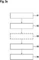
In einem Verfahrensschritt
In einem Verfahrensschritt
Vor oder nach dem Anordnen des Trägers
In einem Verfahrensschritt
Das mittels der
Nachfolgend wird ein Beispiel zum vorteilhaften Detektieren von Formaldehyd (d.h. zum Nachweisen von Formaldehyd oder zur Messung einer Formaldehyd-Konzentration) beschrieben: Zuerst werden die Verfahrensschritte
Nach der fest vorgegebenen Wartezeit/Reaktionszeit wird als Verfahrensschritt
Danach wird das zweite Foto mittels der Bildauswertevorrichtung
Thereafter, the second photo by means of the
Claims (10)
Translated fromGermanPriority Applications (2)
| Application Number | Priority Date | Filing Date | Title |
|---|---|---|---|
| DE102018208049.6ADE102018208049A1 (en) | 2018-05-23 | 2018-05-23 | Framework structure for interaction with an image evaluation device for at least one at least one optochemical detection surface having carrier |
| EP19173058.9AEP3572790B1 (en) | 2018-05-23 | 2019-05-07 | Method for examining a sample medium using a scaffold structure cooperating with an image evaluation device and a holder comprising an optochemical detecting surface |
Applications Claiming Priority (1)
| Application Number | Priority Date | Filing Date | Title |
|---|---|---|---|
| DE102018208049.6ADE102018208049A1 (en) | 2018-05-23 | 2018-05-23 | Framework structure for interaction with an image evaluation device for at least one at least one optochemical detection surface having carrier |
Publications (1)
| Publication Number | Publication Date |
|---|---|
| DE102018208049A1true DE102018208049A1 (en) | 2019-11-28 |
Family
ID=66676975
Family Applications (1)
| Application Number | Title | Priority Date | Filing Date |
|---|---|---|---|
| DE102018208049.6AWithdrawnDE102018208049A1 (en) | 2018-05-23 | 2018-05-23 | Framework structure for interaction with an image evaluation device for at least one at least one optochemical detection surface having carrier |
Country Status (2)
| Country | Link |
|---|---|
| EP (1) | EP3572790B1 (en) |
| DE (1) | DE102018208049A1 (en) |
Families Citing this family (1)
| Publication number | Priority date | Publication date | Assignee | Title |
|---|---|---|---|---|
| DE202020103084U1 (en) | 2020-05-28 | 2021-08-31 | Thomas Lentfort | Portable smartphone scanner |
Citations (33)
| Publication number | Priority date | Publication date | Assignee | Title |
|---|---|---|---|---|
| US3980437A (en)* | 1974-12-21 | 1976-09-14 | Kabushiki Kaisha Kyoto Daiichi Kagaku | Test strips and methods and apparatus for using the same |
| EP0183524A2 (en)* | 1984-11-27 | 1986-06-04 | Syntex (U.S.A.) Inc. | Portable analyzer |
| US4833088A (en)* | 1987-09-25 | 1989-05-23 | Miles Inc. | Reagent strip handling mechanism |
| US4968140A (en)* | 1988-02-02 | 1990-11-06 | Gretag Aktiengesellschaft | Manual device for the determination or measurement of photometric data using a measuring head |
| EP0621481A2 (en)* | 1993-04-23 | 1994-10-26 | Roche Diagnostics GmbH | System for analysing the contents of liquid samples |
| EP0653625A1 (en)* | 1993-11-12 | 1995-05-17 | Unipath Limited | Reading devices for testships |
| WO1996007908A1 (en)* | 1994-09-08 | 1996-03-14 | Lifescan, Inc. | Optically readable strip for analyte detection having on-strip standard |
| US5525297A (en)* | 1993-09-21 | 1996-06-11 | Asulab S.A. | Measurement arrangement for multiple zone removable sensors |
| DE19630160A1 (en)* | 1996-07-26 | 1998-01-29 | Boehringer Mannheim Gmbh | Optical system evaluating quality of fluid distribution onto test piece, e.g. medical test strip |
| EP0618443B1 (en)* | 1993-03-31 | 1998-05-27 | Boehringer Mannheim Gmbh | Test-strip analysis system |
| DE19811622A1 (en)* | 1998-03-17 | 1999-09-23 | Lre Technology Partner Gmbh | Laboratory instrument incorporating split test card housing |
| EP0816849B1 (en)* | 1986-08-13 | 2001-03-21 | Lifescan, Inc. | Method for measuring the concentration of an analyte in whole blood |
| DE10163775A1 (en)* | 2001-12-22 | 2003-07-03 | Roche Diagnostics Gmbh | Analysis system for determining an analyte concentration taking into account sample and analyte-independent changes in light intensity |
| DE10254685A1 (en)* | 2002-11-22 | 2004-06-03 | Roche Diagnostics Gmbh | Measuring device for the optical examination of a test element |
| WO2005036144A1 (en)* | 2003-10-03 | 2005-04-21 | Bayer Healthcare Llc | Precision correction of reflectance measurements |
| DE102005045105A1 (en)* | 2004-12-10 | 2006-06-14 | Agilent Technologies, Inc. (n.d.Ges.d.Staates Delaware), Palo Alto | Diagnostic test using a gated fluorescence quantum dot measurement |
| DE102005056656A1 (en)* | 2005-03-14 | 2006-09-28 | Avago Technologies Ecbu Ip (Singapore) Pte. Ltd. | Portable fluorescence detection unit adapted for eye protection |
| DE102006025714A1 (en)* | 2005-06-01 | 2006-12-14 | Avago Technologies General Ip (Singapore) Pte. Ltd. | Apparatus and method for discriminating among lateral flow assay test indicators |
| DE102006029987A1 (en)* | 2005-10-12 | 2007-04-26 | Agilent Technologies, Inc. (n.d.Ges.d.Staates Delaware), Palo Alto | Optoelectronic halfway disposable diagnostic test system |
| DE102007050411A1 (en)* | 2006-10-25 | 2008-05-08 | Avago Technologies General Ip (Singapore) Pte. Ltd. | Position sensitive indicator detection |
| US8431408B2 (en)* | 2010-10-15 | 2013-04-30 | Roche Diagnostics Operations, Inc. | Handheld diabetes managing device with light pipe for enhanced illumination |
| US8465977B2 (en)* | 2008-07-22 | 2013-06-18 | Roche Diagnostics Operations, Inc. | Method and apparatus for lighted test strip |
| US8570519B2 (en)* | 2009-11-18 | 2013-10-29 | Roche Diagnostics Operations, Inc. | Method and device for analyzing a body fluid |
| DE102012014503A1 (en)* | 2012-07-20 | 2014-01-23 | Dräger Safety AG & Co. KGaA | Gas Detection System |
| DE102013006542A1 (en)* | 2013-04-16 | 2014-10-16 | Dräger Safety AG & Co. KGaA | Measuring device, reaction carrier and measuring method |
| US8894262B2 (en)* | 2013-03-11 | 2014-11-25 | Roche Diagnostic Operations, Inc. | Blood glucose test strip illumination device and method |
| DE102014012434A1 (en)* | 2013-08-20 | 2015-03-12 | opTricon Entwicklungsgesellschaft für Optische Technologien mbH | Device for digital reading for rapid tests |
| DE102014226381A1 (en)* | 2014-12-18 | 2016-06-23 | Robert Bosch Gmbh | Holding device, system and method for optically reading a test strip |
| US9404794B2 (en)* | 2013-02-28 | 2016-08-02 | Lifescan Scotland Limited | Ambient light compensation circuit for analyte measurement systems |
| US9442089B2 (en)* | 2013-12-23 | 2016-09-13 | Lifescan Scotland Limited | Analyte meter test strip detection |
| DE102004027131B4 (en)* | 2003-06-04 | 2017-02-16 | Alere Switzerland Gmbh | Optical arrangement for assay reading device |
| DE102016202428A1 (en)* | 2016-02-17 | 2017-08-17 | Axagarius Gmbh & Co. Kg | Measuring system for colorimetric assays |
| US10036709B2 (en)* | 2014-05-20 | 2018-07-31 | Roche Diabetes Care, Inc. | BG meter illuminated test strip |
Family Cites Families (4)
| Publication number | Priority date | Publication date | Assignee | Title |
|---|---|---|---|---|
| GB2497750B (en)* | 2011-12-19 | 2015-02-25 | Lumophore Ltd | Analysis of colorimetric or fluorometric test assays |
| US10132802B2 (en)* | 2012-04-17 | 2018-11-20 | i-calQ, LLC | Device for performing a diagnostic test and methods for use thereof |
| US9241663B2 (en)* | 2012-09-05 | 2016-01-26 | Jana Care Inc. | Portable medical diagnostic systems and methods using a mobile device |
| US10458902B2 (en)* | 2015-09-13 | 2019-10-29 | Australian Sensing and Indentification Systems Pty. Ltd. | Analysis instrument, associated systems and methods |
- 2018
- 2018-05-23DEDE102018208049.6Apatent/DE102018208049A1/ennot_activeWithdrawn
- 2019
- 2019-05-07EPEP19173058.9Apatent/EP3572790B1/ennot_activeNot-in-force
Patent Citations (34)
| Publication number | Priority date | Publication date | Assignee | Title |
|---|---|---|---|---|
| US3980437A (en)* | 1974-12-21 | 1976-09-14 | Kabushiki Kaisha Kyoto Daiichi Kagaku | Test strips and methods and apparatus for using the same |
| EP0183524A2 (en)* | 1984-11-27 | 1986-06-04 | Syntex (U.S.A.) Inc. | Portable analyzer |
| US6268162B1 (en)* | 1986-08-13 | 2001-07-31 | Lifescan, Inc. | Reflectance measurement of analyte concentration with automatic initiation of timing |
| EP0816849B1 (en)* | 1986-08-13 | 2001-03-21 | Lifescan, Inc. | Method for measuring the concentration of an analyte in whole blood |
| US4833088A (en)* | 1987-09-25 | 1989-05-23 | Miles Inc. | Reagent strip handling mechanism |
| US4968140A (en)* | 1988-02-02 | 1990-11-06 | Gretag Aktiengesellschaft | Manual device for the determination or measurement of photometric data using a measuring head |
| EP0618443B1 (en)* | 1993-03-31 | 1998-05-27 | Boehringer Mannheim Gmbh | Test-strip analysis system |
| EP0621481A2 (en)* | 1993-04-23 | 1994-10-26 | Roche Diagnostics GmbH | System for analysing the contents of liquid samples |
| US5525297A (en)* | 1993-09-21 | 1996-06-11 | Asulab S.A. | Measurement arrangement for multiple zone removable sensors |
| EP0653625A1 (en)* | 1993-11-12 | 1995-05-17 | Unipath Limited | Reading devices for testships |
| WO1996007908A1 (en)* | 1994-09-08 | 1996-03-14 | Lifescan, Inc. | Optically readable strip for analyte detection having on-strip standard |
| DE19630160A1 (en)* | 1996-07-26 | 1998-01-29 | Boehringer Mannheim Gmbh | Optical system evaluating quality of fluid distribution onto test piece, e.g. medical test strip |
| DE19811622A1 (en)* | 1998-03-17 | 1999-09-23 | Lre Technology Partner Gmbh | Laboratory instrument incorporating split test card housing |
| DE10163775A1 (en)* | 2001-12-22 | 2003-07-03 | Roche Diagnostics Gmbh | Analysis system for determining an analyte concentration taking into account sample and analyte-independent changes in light intensity |
| DE10254685A1 (en)* | 2002-11-22 | 2004-06-03 | Roche Diagnostics Gmbh | Measuring device for the optical examination of a test element |
| DE102004027131B4 (en)* | 2003-06-04 | 2017-02-16 | Alere Switzerland Gmbh | Optical arrangement for assay reading device |
| WO2005036144A1 (en)* | 2003-10-03 | 2005-04-21 | Bayer Healthcare Llc | Precision correction of reflectance measurements |
| DE102005045105A1 (en)* | 2004-12-10 | 2006-06-14 | Agilent Technologies, Inc. (n.d.Ges.d.Staates Delaware), Palo Alto | Diagnostic test using a gated fluorescence quantum dot measurement |
| DE102005056656A1 (en)* | 2005-03-14 | 2006-09-28 | Avago Technologies Ecbu Ip (Singapore) Pte. Ltd. | Portable fluorescence detection unit adapted for eye protection |
| DE102006025714A1 (en)* | 2005-06-01 | 2006-12-14 | Avago Technologies General Ip (Singapore) Pte. Ltd. | Apparatus and method for discriminating among lateral flow assay test indicators |
| DE102006029987A1 (en)* | 2005-10-12 | 2007-04-26 | Agilent Technologies, Inc. (n.d.Ges.d.Staates Delaware), Palo Alto | Optoelectronic halfway disposable diagnostic test system |
| DE102007050411A1 (en)* | 2006-10-25 | 2008-05-08 | Avago Technologies General Ip (Singapore) Pte. Ltd. | Position sensitive indicator detection |
| US8465977B2 (en)* | 2008-07-22 | 2013-06-18 | Roche Diagnostics Operations, Inc. | Method and apparatus for lighted test strip |
| US8570519B2 (en)* | 2009-11-18 | 2013-10-29 | Roche Diagnostics Operations, Inc. | Method and device for analyzing a body fluid |
| US8431408B2 (en)* | 2010-10-15 | 2013-04-30 | Roche Diagnostics Operations, Inc. | Handheld diabetes managing device with light pipe for enhanced illumination |
| DE102012014503A1 (en)* | 2012-07-20 | 2014-01-23 | Dräger Safety AG & Co. KGaA | Gas Detection System |
| US9404794B2 (en)* | 2013-02-28 | 2016-08-02 | Lifescan Scotland Limited | Ambient light compensation circuit for analyte measurement systems |
| US8894262B2 (en)* | 2013-03-11 | 2014-11-25 | Roche Diagnostic Operations, Inc. | Blood glucose test strip illumination device and method |
| DE102013006542A1 (en)* | 2013-04-16 | 2014-10-16 | Dräger Safety AG & Co. KGaA | Measuring device, reaction carrier and measuring method |
| DE102014012434A1 (en)* | 2013-08-20 | 2015-03-12 | opTricon Entwicklungsgesellschaft für Optische Technologien mbH | Device for digital reading for rapid tests |
| US9442089B2 (en)* | 2013-12-23 | 2016-09-13 | Lifescan Scotland Limited | Analyte meter test strip detection |
| US10036709B2 (en)* | 2014-05-20 | 2018-07-31 | Roche Diabetes Care, Inc. | BG meter illuminated test strip |
| DE102014226381A1 (en)* | 2014-12-18 | 2016-06-23 | Robert Bosch Gmbh | Holding device, system and method for optically reading a test strip |
| DE102016202428A1 (en)* | 2016-02-17 | 2017-08-17 | Axagarius Gmbh & Co. Kg | Measuring system for colorimetric assays |
Also Published As
| Publication number | Publication date |
|---|---|
| EP3572790A1 (en) | 2019-11-27 |
| EP3572790B1 (en) | 2021-10-13 |
Similar Documents
| Publication | Publication Date | Title |
|---|---|---|
| EP1963828B1 (en) | Method for measuring an analyte concentration in a sample of a biological fluid | |
| EP1705480B1 (en) | Test element for analysing body fluids | |
| DE69913103T2 (en) | OPTICAL SENSOR AND FUNCTIONAL METHOD | |
| DE102016202428B4 (en) | Measuring system for colorimetric assays | |
| DE112012003198T5 (en) | Sensor head, electrochemical sensor and method of using the electrochemical sensor | |
| WO2013143533A1 (en) | Device for identifying samples in a sample arrangement and stand for the device | |
| DE69701642T2 (en) | Glass / cellulose as a protein reagent | |
| DE102009051428A1 (en) | Reagent cartridge for an assembly to selectively perform a clinical chemistry test or an ELISA test | |
| DE60115016T2 (en) | TEST DEVICE WITH TIME ADJUSTMENT FUNCTION | |
| EP3572790B1 (en) | Method for examining a sample medium using a scaffold structure cooperating with an image evaluation device and a holder comprising an optochemical detecting surface | |
| EP1061371B1 (en) | Method and device for controlling the liquid absorption of an analysing element test layer | |
| DE4121493A1 (en) | ANALYSIS DEVICE FOR THE QUANTITATIVE, IMMUNOLOGICAL DETERMINATION OF POLLUTANTS | |
| DE10323897B4 (en) | Method for identifying image positions of a color sample of a test strip | |
| EP2845907B1 (en) | Handheld measuring device and method for the detection of mildew infestation in indoor spaces | |
| EP2658957A1 (en) | Handheld measuring device for detecting concealed mould damage | |
| DE102015218442A1 (en) | Biosensor and method for the detection of germs | |
| EP2594601B1 (en) | Optode | |
| DE10061140A1 (en) | Methods and means for determining total hardness | |
| DE102017209923A1 (en) | A mouthpiece, device, system and method for testing the usability of a mouthpiece for measuring analytes in exhaled air | |
| DE102006055095B3 (en) | Air humidity e.g. condensation humidity, measuring device for use in building, has equipment formed by sensor partly arranged in chamber so that humidity adjustment and surface humidity are measured in chamber and outside cell, respectively | |
| DE10391021B4 (en) | Method for characterizing highly parallelized liquid handling technique using microplates and test kit for carrying out the method | |
| WO2019008461A1 (en) | DEVICE AND METHOD FOR OBTAINING AT LEAST 2D ANALYTICAL INFORMATION AND DETECTING ELEMENT DESIGNATED THEREFOR | |
| DE102012211215A1 (en) | Method and device for detecting the concentration of at least one target gaseous substance and use of a device | |
| DE4340827C1 (en) | Method and device for determining the effectiveness of a skin protection agent | |
| DE102008006806A1 (en) | An immunological method and kit for determining the progesterone content of a sample and apparatus therefor |
Legal Events
| Date | Code | Title | Description |
|---|---|---|---|
| R163 | Identified publications notified | ||
| R119 | Application deemed withdrawn, or ip right lapsed, due to non-payment of renewal fee |