DE102018206172A1 - Method for access control of a device, device for use in the method and vehicle - Google Patents
Method for access control of a device, device for use in the method and vehicleDownload PDFInfo
- Publication number
- DE102018206172A1 DE102018206172A1DE102018206172.6ADE102018206172ADE102018206172A1DE 102018206172 A1DE102018206172 A1DE 102018206172A1DE 102018206172 ADE102018206172 ADE 102018206172ADE 102018206172 A1DE102018206172 A1DE 102018206172A1
- Authority
- DE
- Germany
- Prior art keywords
- distance measurement
- distance
- communication
- uwb
- access
- Prior art date
- Legal status (The legal status is an assumption and is not a legal conclusion. Google has not performed a legal analysis and makes no representation as to the accuracy of the status listed.)
- Ceased
Links
- 238000000034methodMethods0.000titleclaimsabstractdescription30
- 238000005259measurementMethods0.000claimsabstractdescription88
- 238000004891communicationMethods0.000claimsabstractdescription70
- 238000013475authorizationMethods0.000claimsabstractdescription35
- 238000012795verificationMethods0.000claimsabstractdescription6
- 230000005540biological transmissionEffects0.000claimsdescription15
- 230000004044responseEffects0.000claimsdescription8
- 208000035139partial with pericentral spikes epilepsyDiseases0.000description6
- 230000000875corresponding effectEffects0.000description4
- 238000005516engineering processMethods0.000description4
- 238000012545processingMethods0.000description4
- 230000008901benefitEffects0.000description3
- 238000009434installationMethods0.000description3
- 238000012360testing methodMethods0.000description3
- 238000012546transferMethods0.000description3
- 102100036407ThioredoxinHuman genes0.000description2
- 230000001133accelerationEffects0.000description2
- 238000004590computer programMethods0.000description2
- 238000012790confirmationMethods0.000description2
- 238000010586diagramMethods0.000description2
- 238000011156evaluationMethods0.000description2
- 238000010295mobile communicationMethods0.000description2
- 230000006855networkingEffects0.000description2
- 230000008569processEffects0.000description2
- BUHVIAUBTBOHAG-FOYDDCNASA-N(2r,3r,4s,5r)-2-[6-[[2-(3,5-dimethoxyphenyl)-2-(2-methylphenyl)ethyl]amino]purin-9-yl]-5-(hydroxymethyl)oxolane-3,4-diolChemical compoundCOC1=CC(OC)=CC(C(CNC=2C=3N=CN(C=3N=CN=2)[C@H]2[C@@H]([C@H](O)[C@@H](CO)O2)O)C=2C(=CC=CC=2)C)=C1BUHVIAUBTBOHAG-FOYDDCNASA-N0.000description1
- 238000012935AveragingMethods0.000description1
- 101001045846Homo sapiens Histone-lysine N-methyltransferase 2AProteins0.000description1
- 238000013459approachMethods0.000description1
- 238000003491arrayMethods0.000description1
- 230000008859changeEffects0.000description1
- 238000002485combustion reactionMethods0.000description1
- 238000010276constructionMethods0.000description1
- 230000002596correlated effectEffects0.000description1
- 230000001419dependent effectEffects0.000description1
- 238000013461designMethods0.000description1
- 238000011161developmentMethods0.000description1
- 230000018109developmental processEffects0.000description1
- 238000005562fadingMethods0.000description1
- 230000006870functionEffects0.000description1
- 230000007774longtermEffects0.000description1
- 239000000463materialSubstances0.000description1
- 238000012986modificationMethods0.000description1
- 230000004048modificationEffects0.000description1
- 210000003205muscleAnatomy0.000description1
- 230000002035prolonged effectEffects0.000description1
- 238000004904shorteningMethods0.000description1
- 230000003595spectral effectEffects0.000description1
- 230000001360synchronised effectEffects0.000description1
- 230000002123temporal effectEffects0.000description1
- 230000000007visual effectEffects0.000description1
- XLYOFNOQVPJJNP-UHFFFAOYSA-NwaterSubstancesOXLYOFNOQVPJJNP-UHFFFAOYSA-N0.000description1
Images


Classifications
- B—PERFORMING OPERATIONS; TRANSPORTING
- B60—VEHICLES IN GENERAL
- B60R—VEHICLES, VEHICLE FITTINGS, OR VEHICLE PARTS, NOT OTHERWISE PROVIDED FOR
- B60R25/00—Fittings or systems for preventing or indicating unauthorised use or theft of vehicles
- B—PERFORMING OPERATIONS; TRANSPORTING
- B60—VEHICLES IN GENERAL
- B60R—VEHICLES, VEHICLE FITTINGS, OR VEHICLE PARTS, NOT OTHERWISE PROVIDED FOR
- B60R25/00—Fittings or systems for preventing or indicating unauthorised use or theft of vehicles
- B60R25/20—Means to switch the anti-theft system on or off
- B60R25/24—Means to switch the anti-theft system on or off using electronic identifiers containing a code not memorised by the user
- B60R25/245—Means to switch the anti-theft system on or off using electronic identifiers containing a code not memorised by the user where the antenna reception area plays a role
Landscapes
- Engineering & Computer Science (AREA)
- Mechanical Engineering (AREA)
- Lock And Its Accessories (AREA)
Abstract
Translated fromGerman
Description
Translated fromGermanDie Erfindung betrifft ein Verfahren zur Zugriffskontrolle für eine Vorrichtung. Der Vorschlag betrifft weiterhin eine Vorrichtung zur Verwendung bei dem Verfahren sowie ein Fahrzeug.The invention relates to a method for access control for a device. The proposal further relates to a device for use in the method and a vehicle.
Moderne Fahrzeuge werden mit immer mehr elektrischen und elektronischen Komponenten ausgestattet, die den Komfort und die Sicherheit erhöhen. Beispiele sind moderne Fahrerassistenzsysteme, wie:
- • Automatische Distanzregelung ACC
- • Spurhalteassistent
- • Spurwechselassistent
- • Notbremsassistent
- • Stauassistent
- • Lichtassistent.
- • Automatic distance control ACC
- • Lane Keeping Assist
- • Lane Change Assistant
- • Emergency Brake Assist
- • Traffic Jam Assistant
- • Lighting assistant.
Auch die Kommunikationstechnik hält immer mehr Einzug in Fahrzeuge, darunter WiFi, Bluetooth für den Nahbereichsfunk und LTE für die Mobilfunk-Kommunikation. Diese Kommunikationssysteme eröffnen vielfältige neue Anwendungen für das Fahrzeug, bergen aber auch das Risiko, dass durch sie Angreifern (Hackern) ein Zugang zu Systemen des Fahrzeuges ermöglicht wird. Bei diesen Angriffspfaden ist Voraussetzung, dass das Infotainmentsystem in Betrieb ist, also dass zumindest die „Zündung“ (Klemme 50) des Fahrzeuges eingeschaltet ist.Communication technology is also becoming increasingly popular in vehicles, including WiFi, Bluetooth for short-range radio and LTE for mobile communications. These communications systems open up a variety of new applications for the vehicle, but also pose the risk of allowing attackers (hackers) access to vehicle systems. In this attack path is a prerequisite that the infotainment system is in operation, so that at least the "ignition" (terminal 50) of the vehicle is turned on.
Es gibt aber auch ein System im Fahrzeug, das auch bei ausgeschalteter Zündung angreifbar ist. Es handelt sich um das schlüssellose Öffnungssystem, das entweder als Remote-Keyless-Entry-Lösung (RKE) realisiert ist, bei dem der Fahrzeugbesitzer am Schlüssel einen Funkbefehl auslöst, oder - immer häufiger - als Passive-Entry-Passive-Start-System (PEPS), bei dem es genügt, den Schlüssel in der Tasche mitzuführen.But there is also a system in the vehicle, which is vulnerable even when the ignition is switched off. It is the keyless opening system, which is implemented either as a remote keyless entry solution (RKE), in which the vehicle owner triggers a radio command on the key, or - increasingly frequently - as a passive entry passive start system ( PEPS), where it is sufficient to carry the key in the bag.
Dies verlangt nach weiteren Sicherheitsvorkehrungen. Auch die Angreifer setzen auf moderne Technik, um sich Zugang zu verschaffen. So wurden PEPS-Systeme schon dadurch ausgehebelt, dass man zwischen dem Fahrzeug und dem vom Fahrzeug entfernten Schlüssel eine Funkbrücke bestehend aus zwei Transceivern einrichtete, die dem Fahrzeug vorspiegelte, der Schlüssel befände sich in unmittelbarer Nähe.This requires further safety precautions. The attackers also rely on modern technology to gain access. Thus, PEPS systems were already undermined by the fact that between the vehicle and the remote key from the vehicle a radio bridge consisting of two transceivers set up, which mirrored the vehicle, the key was in the immediate vicinity.
Bei solch einem Angriffsszenarium, bei dem sich ein Unberechtigter den Zugang zum Fahrzeug erschleichen möchte, wird die zugehörige Funkstrecke des Berechtigungssystems bzw. die Funkstrecke zwischen Schlüssel und Fahrzeug künstlich verlängert. Dies geschieht so, dass eine Relaisstation mit Antenne nah (typsicherweise weniger als 2 Meter) am Fahrzeug positioniert wird und die andere Relaisstation mit Antenne nah an dem autorisierten Berechtigungsmittel (typischerweise weniger als 2 Meter), also dem Schlüssel des Fahrers. Hierbei handelt es sich um sogenannte Relaisangriffe, die in der Fachwelt unter der Bezeichnung Relay Station Attack (RSA) bekannt sind.In such an attack scenario, in which an unauthorized person would like to gain access to the vehicle, the associated radio link of the authorization system or the radio link between the key and the vehicle is artificially prolonged. This is done by placing one relay station with antenna close to (typically less than 2 meters) the vehicle and the other relay station with antenna close to the authorized authorization means (typically less than 2 meters), ie the driver's key. These are so-called relay attacks, which are known in the art as Relay Station Attack (RSA).
Aus der
Bis vor Kurzem wurde für RKE- / PEPS-Systeme ein Mix von Drahtlos-Kommunikationstechnologien genutzt: Im LF-Bereich (z. B. 125 kHz) wurde ein Beacon-Signal zum Aufwecken der Komponenten eingesetzt. Für die verschlüsselte Kommunikation wurde der UHF-Bereich (z. B. 433 MHz) benutzt. Schließlich wurde der LF-Bereich (z. B. 21 kHz) eingesetzt für ein magnetisches Kompasssystem im Fahrzeuginnern zur Prüfung, ob sich der Schlüssel drinnen oder draußen befindet. Da sich diese Systeme als angreifbar erwiesen haben, geht der Trend inzwischen zu einer Lösung mit nur einem Funkstandard auf UWB-Basis (Ultra Wide Band) im Frequenzbereich 3,1 GHz bis 10,6 GHz, in dem verschiedene Bänder dafür vorgesehen sind.Until recently, a mix of wireless communication technologies was used for RKE / PEPS systems: in the LF range (eg 125 kHz), a beacon signal was used to wake up the components. For encrypted communication the UHF range (eg 433 MHz) was used. Finally, the LF range (eg, 21 kHz) has been used for a magnetic compass system inside the vehicle to check whether the key is inside or outside. As these systems have proved to be vulnerable, the trend is now towards a solution with only one UWB-based (Ultra Wide Band) radio standard in the frequency range 3.1 GHz to 10.6 GHz, in which various bands are provided for this purpose.
UWB ist eine generelle Bezeichnung für sehr kurze, gepulste Signale niedriger Energie, die eine große Bandbreite von mehr als 500 MHz nutzen. Die reziproke Beziehung zwischen Zeit und Bandbreite ist der Hauptgrund für die Wahl dieses Verfahrens, denn durch die Investition in Bandbreite kann die Signaldauer entsprechend kurz ausfallen. Das wiederum ist aus mehreren Gründen wünschenswert. Zum einen kommt es bei Pulsdauern im Nanosekundenbereich nicht zur Überlagerung des Originalsignals mit Reflexionen, was die Eindeutigkeit des Signals gewährleistet. Zum anderen lässt sich wegen der zeitlichen Schärfe der Pulse deren Laufzeit und damit die Senderentfernung präzise bestimmen, sodass die aufwendige Magnetfeldmessung zur Positionsbestimmung des Schlüssels entfallen kann. Die Tatsache, dass der UWB-Funk außerdem mit sehr geringen Sendeleistungen und Signal-Rausch-Abständen operiert, verlängert die Batterielaufzeit, vermeidet die Störung anderer Funkteilnehmer und begrenzt die Reichweite, was ein Abfangen des Signals durch Hacker erschwert. Auch die Weiterleitung des UWB-Signals über Relaisstationen über größere Entfernungen stößt auf Schwierigkeiten. Weil aber die RSA Attacke bereits bei der zuvor eingesetzten Technik zur Zugangskontrolle eingesetzt wurde, steht es zu befürchten, dass ähnliche Attacken auch bei dem neueren System auf Basis von UWB-Signalen versucht werden.UWB is a generic term for very short, pulsed, low-energy signals that use a wide bandwidth of more than 500 MHz. The reciprocal relationship between time and bandwidth is the main reason for choosing this method because investing in bandwidth can make the signal duration correspondingly short. This in turn is desirable for several reasons. On the one hand, with pulse durations in the nanosecond range, there is no overlapping of the original signal with reflections, which ensures the uniqueness of the signal. On the other hand, because of the temporal sharpness of the pulses, their transit time and thus the transmitter distance can be precisely determined so that the complex magnetic field measurement for determining the position of the key can be dispensed with. The The fact that the UWB radio also operates at very low transmit power and signal-to-noise ratios extends battery life, avoids interference with other radio subscribers, and limits range, making it difficult for hackers to intercept the signal. The forwarding of the UWB signal via relay stations over long distances encounters difficulties. But since the RSA attack was already used in the previously used technology for access control, it is to be feared that similar attacks will be tried on the newer system based on UWB signals.
Es besteht deshalb der Bedarf für zusätzliche Gegenmaßnahmen, um solchen Angriffen zu entgehen. Dies wurde im Rahmen der Erfindung erkannt.There is therefore a need for additional countermeasures to avoid such attacks. This was recognized within the scope of the invention.
Die Erfindung setzt sich zur Aufgabe, die Zugangskontrolle für RKE- / PEPS-Systeme weiter zu verbessern. Hier wird insbesondere der Fokus darauf gelegt, eine Attacke, die darauf beruht, dass eine UWB-Transceiver-Einheit in die Nähe des Schlüssels gebracht wird, zu unterbinden. Typischerweise werden an allen Ecken des Fahrzeuges UWB-Transceiver-Einheiten installiert, die innerhalb des Motorraums und Kofferraums angebracht sind und deshalb von außen nicht zugänglich sind. Für professionelle Fahrzeugdiebe stellt dies oft kein Hindernis dar. Sie werden sich mit Gewalt oder professionellen Werkzeugen Zugang verschaffen und könnten in der Lage sein, eine UWB-Transceiver-Box auszubauen und das Anschlusskabel zu verlängern. Die ausgebaute Box könnte in die Nähe des Fahrzeugführers gebracht werden, um so die Wegfahrsperre zu entriegeln, wodurch das Fahrzeug dann entwendet werden kann.The object of the invention is to further improve access control for RKE / PEPS systems. In particular, the focus here is on preventing an attack based on bringing a UWB transceiver unit near the key. Typically, UWB transceiver units are installed at all corners of the vehicle, which are mounted within the engine compartment and trunk and therefore are not accessible from the outside. For professional vehicle thieves this is often not an obstacle. They will gain access by force or professional tools and may be able to extend a UWB transceiver box and extend the connection cable. The removed box could be brought close to the driver so as to unlock the immobilizer, whereby the vehicle can then be stolen.
Diese Aufgabe wird durch ein Verfahren zur Durchführung von Abstandsmessungen zwischen den Kommunikations-Boxen des Fahrzeuges gemäß Anspruch 1, ein Vorrichtung zur Verwendung bei dem Verfahren gemäß Anspruch 10 und ein Fahrzeug gemäß Anspruch 14 gelöst.This object is achieved by a method for performing distance measurements between the communication boxes of the vehicle according to claim 1, an apparatus for use in the method according to
Die abhängigen Ansprüche beinhalten vorteilhafte Weiterbildungen und Verbesserungen der Erfindung entsprechend der nachfolgenden Beschreibung dieser Maßnahmen.The dependent claims contain advantageous developments and improvements of the invention according to the following description of these measures.
Die erfindungsgemäße Lösung betrifft ein Verfahren zur Zugriffskontrolle für eine Vorrichtung, wobei die Vorrichtung mit wenigstens zwei Kommunikationsmodulen ausgestattet ist, die zur drahtlosen Kommunikation mit einem Authentifizierungselement ausgelegt sind. Es wird von dem Authentifizierungselement eine Zugangsberechtigungsinformation zur Vorrichtung übertragen. In der Vorrichtung wird die Zugangsberechtigungsinformation überprüft, wobei nach Verifikation der Zugangsberechtigungsinformation der Zugriff auf die Vorrichtung gewährt wird. Das Verfahren kennzeichnet sich dadurch aus, dass eine Abstandsmessung wenigstens zwischen zwei Kommunikationsmodulen durchgeführt wird und dass der Zugriff auf die Vorrichtung unterbunden wird, wenn bei der Abstandsmessung festgestellt wird, dass der Abstand zwischen den Kommunikationsmodulen außerhalb eines Sollbereiches liegt oder die Abstandsmessung gar nicht durchführbar ist. Durch dieses Verfahren wird die Erschleichung des Zugangs zur Vorrichtung mit Hilfe einer Attacke, bei der eine Kommunikations-Box elektrisch verlängert wird, zuverlässig unterbunden.The inventive solution relates to a method for access control for a device, wherein the device is equipped with at least two communication modules, which are designed for wireless communication with an authentication element. The authentication element transmits access authorization information to the device. In the device, the access authorization information is checked, wherein access to the device is granted after verification of the access authorization information. The method is characterized in that a distance measurement is performed at least between two communication modules and that the access to the device is inhibited if it is determined during the distance measurement that the distance between the communication modules is outside a desired range or the distance measurement is not feasible , By this method, the fading of access to the device by means of an attack in which a communication box is electrically extended, reliably prevented.
Es ist vorteilhaft, wenn die Kommunikationsmodule für die UWB-Kommunikation entsprechend Ultra Wide Band-Kommunikation ausgelegt sind. Dies hat bereits diverse Vorteile hinsichtlich Störungen von anderen Funkausstrahlungen, Batterielaufzeit und Reichweitenverkürzung, um Hackerangriffe zu erschweren. Ein weiterer Vorteil besteht noch darin, dass die verwendeten UWB-Transceiver auch gut für die Abstandsmessungen eingesetzt werden können. Solch eine Abstandsmessung mit UWB-Signalen, die im für die UWB Kommunikation zulässigen Frequenzbereich zwischen 3,1 bis 10,6 GHz ablaufen, beruht auf einer Laufzeitmessung. Diese Messung ist auch unter dem Begriff Time of Flight-Messung TOF bekannt. Weil die Messung in dem Bereich mit Dezimeterwellen stattfindet, ist die Messung unter Sichtbedingungen, auch Line of Sight LOS-Bedingung genannt, bis auf 10 cm genau.It is advantageous if the communication modules are designed for UWB communication according to Ultra Wide Band communication. This already has several advantages in terms of interference from other radio broadcasts, battery life and range shortening to hacker attacks difficult. Another advantage is that the UWB transceivers used can also be used well for distance measurements. Such a distance measurement with UWB signals, which take place in the frequency range between 3.1 to 10.6 GHz permissible for the UWB communication, is based on a transit time measurement. This measurement is also known by the term Time of Flight Measurement TOF. Since the measurement takes place in the range of decimetric waves, the measurement under visual conditions, also called the line of sight LOS condition, is accurate to within 10 cm.
Dabei ist es weiterhin vorteilhaft, wenn das Authentifizierungselement ebenfalls für die UWB-Kommunikation ausgelegt wird. Entsprechend sollte zwischen wenigstens einem der Kommunikationsmodule und dem Authentifizierungselement ebenfalls eine Abstandsmessung durchgeführt werden und der Zugriff auf die Vorrichtung unterbunden werden, wenn bei der Abstandsmessung festgestellt wird, dass der Abstand zwischen dem Kommunikationsmodul und dem Authentifizierungselement außerhalb eines Sollbereiches liegt oder die Abstandsmessung gar nicht durchführbar ist.It is also advantageous if the authentication element is also designed for the UWB communication. Correspondingly, a distance measurement should also be carried out between at least one of the communication modules and the authentication element and the access to the device should be prevented if it is determined during the distance measurement that the distance between the communication module and the authentication element is outside a desired range or the distance measurement is not feasible is.
In vorteilhafter Weise werden bei dem Verfahren die Abstandsmessungen in der Vorrichtung ausgewertet. Dadurch wird das Authentifizierungselement von solchen Aufgaben entlastet und kann entsprechend einfacher gestaltet werden.Advantageously, the distance measurements in the device are evaluated in the method. As a result, the authentication element is relieved of such tasks and can be made correspondingly simpler.
Eine vorteilhafte Maßnahme besteht darin, dass die Startzeitpunkte für die Abstandsmessungen zwischen dem Authentifizierungselement und wenigstens einem der Kommunikationsmodule einerseits und zwischen wenigstens zwei der Kommunikationsmodule andererseits durch die Vorrichtung vorgegeben werden, sodass die Einzelabstandsmessungen nacheinander durchgeführt werden, um eine gegenseitige Störung der Einzelabstandsmessungen zu vermeiden.An advantageous measure is that the start times for the distance measurements between the authentication element and at least one of the communication modules on the one hand and between at least two of the communication modules on the other hand are specified by the device, so that the individual distance measurements are performed sequentially to a mutual interference of the individual distance measurements to avoid.
Dabei ist es vorteilhaft, wenn von einem Zugriffsberechtigungs-Kontrollmodul vorgegeben wird, von welchem Kommunikationsmodul das UWB-Signal für die Abstandsmessung ausgestrahlt werden soll.It is advantageous if it is predetermined by an access authorization control module, from which communication module the UWB signal for the distance measurement is to be broadcast.
Dabei ist es von Vorteil, dass das Zugriffsberechtigungs-Kontrollmodul dasjenige Kommunikationsmodul mit der Ausstrahlung des UWB-Signals für die Abstandsmessung beauftragt, von dem es die Zugangsberechtigungsinformation erhalten hat. So kommt es nicht zu einer Ausstrahlung von störenden UWB-Signalen.It is advantageous that the access authorization control module instructs that communication module with the transmission of the UWB signal for the distance measurement, from which it has received the access authorization information. So it does not come to a broadcast of disturbing UWB signals.
Weiterhin ist es vorteilhaft, wenn das UWB-Signal für die Abstandsmessung sowohl eine Adressinformation beinhaltet, an welche Komponente das UWB-Signal gerichtet ist, als auch einen Zeitstempel für den Sendezeitpunkt des UWB-Signals. So wird verhindert, dass ein Kommunikationsmodul oder das Authentifizierungselement auf die UWB-Signale antwortet, das bei der Messung gar nicht betroffen ist.Furthermore, it is advantageous if the UWB signal for the distance measurement contains both an address information, to which component the UWB signal is directed, as well as a time stamp for the transmission time of the UWB signal. This prevents a communication module or the authentication element from responding to the UWB signals that are not affected during the measurement.
Weiterhin ist es von Vorteil, wenn in der Rückantwort ein Zeitstempel für den Empfangszeitpunkt des UWB-Signals eingetragen wird und ein Zeitstempel für den Sendezeitpunkt der Rückantwort. Dann muss es im Kommunikationsmodul, das die Messung gestartet hat, nicht bekannt sein, wie lange die Verarbeitung in dem Kommunikationsmodul, zu dem der Abstand gemessen wird, dauert.Furthermore, it is advantageous if a timestamp for the reception time of the UWB signal is entered in the response and a timestamp for the transmission time of the response. Then, in the communication module that started the measurement, it need not be known how long the processing lasts in the communication module to which the distance is measured.
Für eine Vorrichtung zur Verwendung bei dem Verfahren ist es vorteilhaft, dass sie wenigstens zwei Kommunikationsmodule aufweist, die zur drahtlosen Kommunikation mit einem Authentifizierungselement ausgelegt sind. Weiterhin ist ein Zugriffsberechtigungs-Kontrollmodul vorgesehen, das ausgelegt ist, nach Verifikation der Zugriffsberechtigungsinformation den Zugriff auf die Vorrichtung zu gewähren. Diese Vorrichtung zeichnet sich weiter dadurch aus, dass ein Kommunikationsmodul vorgesehen ist, das nach Empfang einer Zugriffsberechtigungsinformation eine Abstandsmessung zu wenigstens einem weiteren Kommunikationsmodul durchführt und dass das Zugriffsberechtigungs-Kontrollmodul den Zugriff auf die Vorrichtung dann unterbindet, obwohl die Zugriffsberechtigungsinformation empfangen wurde, wenn bei der Auswertung der Abstandsmessung festgestellt wird, dass der Abstand zwischen den Kommunikationsmodulen außerhalb eines Sollbereiches liegt oder die Abstandsmessung gar nicht durchführbar ist. Auf diese Weise wird eine Plausibilierung des Verbauortes der Kommunikationsmodule erreicht und es können Manipulationen hinsichtlich des Ausbaus eines Moduls und dessen elektrischer Verlängerung aufgedeckt werden. Das Zugangsberechtigungssystem ist dadurch sicherer im Hinblick auf diese Attacken.For an apparatus for use in the method, it is advantageous that it has at least two communication modules designed for wireless communication with an authentication element. Furthermore, an access authorization control module is provided, which is designed to grant access to the device after verification of the access authorization information. This device is further distinguished by the fact that a communication module is provided which, after receiving an access authorization information, performs a distance measurement to at least one further communication module and that the access authorization control module then blocks access to the device, although the access authorization information was received when the access authorization information was received Evaluation of the distance measurement is found that the distance between the communication modules is outside a desired range or the distance measurement is not feasible. In this way, a plausibility of the installation location of the communication modules is achieved and it can be uncovered manipulations regarding the expansion of a module and its electrical extension. The conditional access system is thus safer with regard to these attacks.
Weitere Vorteile für die Vorrichtung ergeben sich aus den entsprechenden Maßnahmen, wie bei dem erfindungsgemäßen Verfahren erläutert.Further advantages for the device result from the corresponding measures, as explained in the method according to the invention.
Der Vorschlag betrifft ebenfalls ein Fahrzeug, in dem eine erfindungsgemäße Vorrichtung verbaut ist.The proposal also relates to a vehicle in which a device according to the invention is installed.
Ein Ausführungsbeispiel der Erfindung ist in den Zeichnungen dargestellt und wird nachfolgend anhand der Figuren näher erläutert.An embodiment of the invention is illustrated in the drawings and will be explained in more detail with reference to FIGS.
Es zeigen:
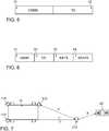
1 das Prinzip der Kommunikation zwischen einem Authentifizierungselement und einem Fahrzeug;2 eine Darstellung, zwischen welchen Komponenten die UWB-Abstandsmessungen durchgeführt werden;3 ein Blockdiagramm für die Fahrzeugelektronik eines Kraftfahrzeuges;4 ein Flussdiagramm für ein Computerprogramm, das in einem Zugriffsberechtigungs-Kontrollmodul entsprechend des Vorschlages abgearbeitet wird,5 das Format eines UWB-Signals zur Abstandsmessung;6 das Format einer Rückantwort bei der UWB-Abstandsmessung zwischen zwei Kommunikationsmodulen, und;7 eine Darstellung der UWB-Abstandsmessungen für den Fall, dass eine Attacke auf Basis der Verlängerung eines Kommunikationsmoduls stattfindet.
1 the principle of communication between an authentication element and a vehicle;2 a representation between which components the UWB distance measurements are performed;3 a block diagram for the vehicle electronics of a motor vehicle;4 a flowchart for a computer program that is processed in an access control module according to the proposal,5 the format of a UWB signal for distance measurement;6 the format of a response in the UWB distance measurement between two communication modules, and;7 a representation of the UWB distance measurements in the event that an attack based on the extension of a communication module takes place.
Die vorliegende Beschreibung veranschaulicht die Prinzipien der erfindungsgemäßen Offenbarung. Es versteht sich somit, dass Fachleute in der Lage sein werden, verschiedene Anordnungen zu konzipieren, die zwar hier nicht explizit beschrieben werden, die aber Prinzipien der erfindungsgemäßen Offenbarung verkörpern und in ihrem Umfang ebenfalls geschützt sein sollen.The present description illustrates the principles of the disclosure of the invention. It will thus be understood that those skilled in the art will be able to devise various arrangements which, while not explicitly described herein, are intended to embody principles of the invention and to be equally limited in scope.
Der Begriff Fahrzeug versteht sich als Sammelbegriff, sei es für Kraftfahrzeuge mit Brennkraftmaschine oder Elektromotor, sei es für Fahrräder mit und ohne Elektromotor oder andere, mit Muskelkraft betriebene Fahrzeuge, sei es für Fahrzeuge mit einem, zwei, vier oder mehr Rädern, sei es für Motorräder, Personenkraftwagen, Lastkraftwagen, Busse, Landwirtschaftsfahrzeuge oder Baumaschinen. Die Aufzählung ist nicht abschließend und umfasst auch weitere Fahrzeugkategorien wie Schienen-, Luft- und Wasserfahrzeuge.The term vehicle is understood as a collective term, be it for motor vehicles with internal combustion engine or electric motor, be it for bicycles with and without electric motor or other powered by muscle power vehicles, be it for vehicles with one, two, four or more wheels, be it for Motorcycles, passenger cars, trucks, buses, agricultural vehicles or construction machinery. The list is not exhaustive and includes other vehicle categories such as rail, air and water vehicles.
Zur besseren Erreichbarkeit der UWB-Signale von dem Authentifizierungselement
Die Abstandsmessung zwischen UWB-Transceiver-Box und Authentifizierungselement
Die Genauigkeit der Abstandsmessung bei solchen UWB Abstandsmesssystemen liegt bei 10 cm in Sichtlinienverhältnissen LOS (Line of Sight Conditions). Das gilt auch, wenn die UWB Transceiver sehr nah beieinander positioniert sind (≤1m Abstand). Bei dem betrachteten Zugangskontrollsystem sind die Transceiver-Boxen mit den UWB-Antennen jeweils an den Ecken des Fahrzeuges
Im Kraftfahrzeug befinden sich dann auch noch weitere elektronische Vorrichtungen. Diese sind mehr im Bereich der Fahrgastzelle angeordnet und werden oft auch von dem Fahrer bedient. Als Beispiel ist in
Das moderne Kraftfahrzeug kann aber noch weitere Komponenten aufweisen wie Videokameras, z.B. als Rückfahrkamera oder als Fahrerüberwachungskamera oder auch als Frontkamera, um das Verkehrsgeschehen zu beobachten. Eine Kamera ist in
Zu dem Zweck, dass fahrzeugrelevante Sensordaten über das Kommunikationsmodul
Nachfolgend wird die Funktionsweise des Zugriffskontrollsystem näher erläutert.
Sind die Abstände im Sollbereich, erfolgt im Schritt
Dabei werden zweite UWB-Abstandsmessungen durchgeführt. Dabei wird der Abstand zwischen mindestens zwei benachbarten Transceiver-Boxen
In einer erweiterten Ausgestaltung wird auch der Abstand zwischen der Transceiver-Box
Wird im Schritt
Das UWB-Signal für die erste Abstandsmessung hat dabei das in
Das UWB-Signal für die zweite Abstandsmessung hat ebenfalls das in
Die prinzipielle Funktionsweise dieser Zugriffskontrolle ist in
Es sollte verstanden werden, dass das vorgeschlagene Verfahren und die zugehörigen Vorrichtungen in verschiedenen Formen von Hardware, Software, Firmware, Spezialprozessoren oder einer Kombination davon implementiert werden können. Spezialprozessoren können anwendungsspezifische integrierte Schaltungen (ASICs), Reduced Instruction Set Computer (RISC) und / oder Field Programmable Gate Arrays (FPGAs) umfassen. Vorzugsweise wird das vorgeschlagene Verfahren und die Vorrichtung als eine Kombination von Hardware und Software implementiert. Die Software wird vorzugsweise als ein Anwendungsprogramm auf einer Programmspeichervorrichtung installiert. Typischerweise handelt es sich um eine Maschine auf Basis einer Computerplattform, die Hardware aufweist, wie beispielsweise eine oder mehrere Zentraleinheiten (CPU), einen Direktzugriffsspeicher (RAM) und eine oder mehrere Eingabe/Ausgabe (I/O) Schnittstelle(n). Auf der Computerplattform wird typischerweise außerdem ein Betriebssystem installiert. Die verschiedenen Prozesse und Funktionen, die hier beschrieben wurden, können Teil des Anwendungsprogramms sein oder ein Teil, der über das Betriebssystem ausgeführt wird.It should be understood that the proposed method and apparatus may be implemented in various forms of hardware, software, firmware, special purpose processors, or a combination thereof. Special purpose processors may include Application Specific Integrated Circuits (ASICs), Reduced Instruction Set Computer (RISC), and / or Field Programmable Gate Arrays (FPGAs). Preferably, the proposed method and apparatus is implemented as a combination of hardware and software. The software is preferably installed as an application program on a program storage device. Typically, it is a machine platform based on a computer platform that includes hardware, such as one or more central processing units (CPU), random access memory (RAM), and one or more input / output (I / O) interface (s). The computer platform also typically installs an operating system. The various processes and functions described herein may be part of the application program or part that is executed via the operating system.
Die Offenbarung ist nicht auf die hier beschriebenen Ausführungsbeispiele beschränkt. Es gibt Raum für verschiedene Anpassungen und Modifikationen, die der Fachmann aufgrund seines Fachwissens als auch zu der Offenbarung zugehörend in Betracht ziehen würde. Zwar wurde die Erfindung am Beispiel eines Zugriffberechtigungskontrollsystems für ein Fahrzeug beschrieben, ein solches Zugriffsberechtigungssystem kann auch für verschiedene andere Vorrichtungen eingesetzt werden. Beispiele sind Maschinensteuerungen, Türöffnungssysteme, Computersysteme usw.The disclosure is not limited to the embodiments described herein. There is room for various adjustments and modifications that would be considered by those skilled in the art, as well as to the disclosure. Although the invention has been described using the example of an access authorization control system for a vehicle, such an access authorization system can also be used for various other devices. Examples are machine controls, door opening systems, computer systems, etc.
BezugszeichenlisteLIST OF REFERENCE NUMBERS
- 1010
- Fahrzeugvehicle
- 4040
- Authentifizierungselementauthentication element
- 100100
- Blockdiagramm Fahrzeug-ElektronikBlock diagram vehicle electronics
- 102102
- Ethernet-BusEthernet bus
- 105105
- Kameracamera
- 104104
- CAN-BusCAN bus
- 108108
- CAN-BusCAN bus
- 110110
- On-Board UnitOn-board unit
- 120120
- Navigationssystemnavigation system
- 140140
- Gatewaygateway
- 151151
- Motor-SteuergerätMotor control unit
- 152152
- ESP-SteuergerätESP control unit
- 153153
- Getriebe-SteuergerätTransmission controller
- 161161
- Sensor 1Sensor 1
- 162162
- Sensor 2
Sensor 2 - 163163
- Sensor 3Sensor 3
- 171171
- BenutzerschnittstellenvorrichtungUser interface device
- 172172
- 1. UWB Transceiver-Box1. UWB transceiver box
- 173173
- 2. UWB Transceiver-Box2. UWB transceiver box
- 174174
- 3. UWB Transceiver-Box3. UWB transceiver box
- 175175
- 4. UWB Transceiver-Box4. UWB transceiver box
- 17121712
- Zugriffsberechtigungs-KontrollmodulAccess authorization control module
- 300300
- Computerprogrammcomputer program
- 320- 390320- 390
- verschiedene Programmschrittedifferent program steps
ZITATE ENTHALTEN IN DER BESCHREIBUNG QUOTES INCLUDE IN THE DESCRIPTION
Diese Liste der vom Anmelder aufgeführten Dokumente wurde automatisiert erzeugt und ist ausschließlich zur besseren Information des Lesers aufgenommen. Die Liste ist nicht Bestandteil der deutschen Patent- bzw. Gebrauchsmusteranmeldung. Das DPMA übernimmt keinerlei Haftung für etwaige Fehler oder Auslassungen.This list of the documents listed by the applicant has been generated automatically and is included solely for the better information of the reader. The list is not part of the German patent or utility model application. The DPMA assumes no liability for any errors or omissions.
Zitierte PatentliteraturCited patent literature
- WO 2016/202592 A1 [0007]WO 2016/202592 A1 [0007]
Zitierte Nicht-PatentliteraturCited non-patent literature
- ISO 11898 [0035]ISO 11898 [0035]
- ISO 11898-2 [0037]ISO 11898-2 [0037]
Claims (14)
Translated fromGermanPriority Applications (1)
| Application Number | Priority Date | Filing Date | Title |
|---|---|---|---|
| DE102018206172.6ADE102018206172A1 (en) | 2018-04-20 | 2018-04-20 | Method for access control of a device, device for use in the method and vehicle |
Applications Claiming Priority (1)
| Application Number | Priority Date | Filing Date | Title |
|---|---|---|---|
| DE102018206172.6ADE102018206172A1 (en) | 2018-04-20 | 2018-04-20 | Method for access control of a device, device for use in the method and vehicle |
Publications (1)
| Publication Number | Publication Date |
|---|---|
| DE102018206172A1true DE102018206172A1 (en) | 2019-05-02 |
Family
ID=66138331
Family Applications (1)
| Application Number | Title | Priority Date | Filing Date |
|---|---|---|---|
| DE102018206172.6ACeasedDE102018206172A1 (en) | 2018-04-20 | 2018-04-20 | Method for access control of a device, device for use in the method and vehicle |
Country Status (1)
| Country | Link |
|---|---|
| DE (1) | DE102018206172A1 (en) |
Citations (3)
| Publication number | Priority date | Publication date | Assignee | Title |
|---|---|---|---|---|
| DE19957536C2 (en)* | 1999-11-30 | 2003-04-03 | Siemens Ag | Anti-theft system for a motor vehicle and method for operating an anti-theft system |
| WO2016202592A1 (en) | 2015-06-15 | 2016-12-22 | Hella Kgaa Hueck & Co. | Access and driving authorisation system with increased safety against relay attacks by verification of the determination of location |
| DE102016207110A1 (en)* | 2016-04-27 | 2017-11-02 | Continental Automotive Gmbh | Method and devices for detecting changes in positions of transmitting and / or receiving devices, such as in particular motor vehicle transceivers relative to each other |
- 2018
- 2018-04-20DEDE102018206172.6Apatent/DE102018206172A1/ennot_activeCeased
Patent Citations (3)
| Publication number | Priority date | Publication date | Assignee | Title |
|---|---|---|---|---|
| DE19957536C2 (en)* | 1999-11-30 | 2003-04-03 | Siemens Ag | Anti-theft system for a motor vehicle and method for operating an anti-theft system |
| WO2016202592A1 (en) | 2015-06-15 | 2016-12-22 | Hella Kgaa Hueck & Co. | Access and driving authorisation system with increased safety against relay attacks by verification of the determination of location |
| DE102016207110A1 (en)* | 2016-04-27 | 2017-11-02 | Continental Automotive Gmbh | Method and devices for detecting changes in positions of transmitting and / or receiving devices, such as in particular motor vehicle transceivers relative to each other |
Non-Patent Citations (2)
| Title |
|---|
| ISO 11898 |
| ISO 11898-2 |
Similar Documents
| Publication | Publication Date | Title |
|---|---|---|
| DE102019212231B4 (en) | Method for door or hatch operation in a vehicle and authentication element | |
| DE102014224481B4 (en) | Remote control of vehicle functionalities using a mobile device | |
| EP3236427B1 (en) | Method and system for passive access control | |
| EP2514161B1 (en) | Method for communicating between a first motor vehicle and at least one second motor vehicle | |
| EP2931567B1 (en) | System allowing a service provider to selectively open a vehicle | |
| DE112019001846T5 (en) | ELECTRONIC VEHICLE KEY SYSTEM | |
| DE112020000634T5 (en) | VEHICLE POSITION ESTIMATION SYSTEM | |
| DE102016112918A1 (en) | Vehicle Peps system using directional sensors | |
| EP3695389B1 (en) | Communications system of a vehicle | |
| WO2016202592A1 (en) | Access and driving authorisation system with increased safety against relay attacks by verification of the determination of location | |
| DE102018101959A1 (en) | TELEPHONE ALS KEY LOCALIZATION BASED ON OBJECT DETECTION | |
| DE102011088917B4 (en) | Access arrangement in the method for operating such an access arrangement | |
| DE102008010056A1 (en) | A system and method for controlling information access to a mobile platform | |
| DE102019205368A1 (en) | Motor vehicle | |
| EP3100242A1 (en) | Mobile device for a keyless access or actuation system for motor vehicles | |
| DE102022101465A1 (en) | RUNTIME LOCATION OF A VEHICLE USER | |
| EP3347246B1 (en) | Method and arrangement for localizing a portable radio unit | |
| DE102017112166A1 (en) | METHOD AND DEVICE FOR A KEYCHAIN WITH TRANSFER ATTACK DETECTION SYSTEM | |
| DE102020105627A1 (en) | Method for controlling a motor vehicle by means of a mobile terminal external to the vehicle and a system with a motor vehicle and a mobile terminal, as well as a motor vehicle and a mobile terminal | |
| EP3734559B1 (en) | Safety system for a vehicle | |
| DE102015226631A1 (en) | Method for releasing one or more functions in a vehicle | |
| EP2825425B1 (en) | Locking system, especially for a motor vehicle | |
| DE102018206172A1 (en) | Method for access control of a device, device for use in the method and vehicle | |
| EP2825424B1 (en) | Locking system, especially for a motor vehicle | |
| DE10322616A1 (en) | Vehicle security system |
Legal Events
| Date | Code | Title | Description |
|---|---|---|---|
| R012 | Request for examination validly filed | ||
| R230 | Request for early publication | ||
| R002 | Refusal decision in examination/registration proceedings | ||
| R003 | Refusal decision now final |