DE102018205721A1 - Blade for a turbomachine and use and manufacturing method thereof - Google Patents
Blade for a turbomachine and use and manufacturing method thereofDownload PDFInfo
- Publication number
- DE102018205721A1 DE102018205721A1DE102018205721.4ADE102018205721ADE102018205721A1DE 102018205721 A1DE102018205721 A1DE 102018205721A1DE 102018205721 ADE102018205721 ADE 102018205721ADE 102018205721 A1DE102018205721 A1DE 102018205721A1
- Authority
- DE
- Germany
- Prior art keywords
- blade
- cooling
- cooling channels
- channels
- heat
- Prior art date
- Legal status (The legal status is an assumption and is not a legal conclusion. Google has not performed a legal analysis and makes no representation as to the accuracy of the status listed.)
- Withdrawn
Links
- 238000004519manufacturing processMethods0.000titleclaimsabstractdescription17
- 238000001816coolingMethods0.000claimsabstractdescription199
- 239000002826coolantSubstances0.000claimsabstractdescription14
- 239000000654additiveSubstances0.000claimsdescription10
- 230000000996additive effectEffects0.000claimsdescription10
- 238000010521absorption reactionMethods0.000claimsdescription5
- 239000011324beadSubstances0.000claimsdescription3
- 230000008859changeEffects0.000claimsdescription3
- 239000012530fluidSubstances0.000description5
- 239000000463materialSubstances0.000description5
- 238000000034methodMethods0.000description4
- 101100116570Caenorhabditis elegans cup-2 geneProteins0.000description3
- 101100116572Drosophila melanogaster Der-1 geneProteins0.000description3
- 230000008901benefitEffects0.000description3
- 238000010276constructionMethods0.000description3
- 230000000694effectsEffects0.000description3
- 238000004891communicationMethods0.000description2
- 230000001419dependent effectEffects0.000description2
- 238000013461designMethods0.000description2
- 239000000835fiberSubstances0.000description2
- 238000012986modificationMethods0.000description2
- 230000004048modificationEffects0.000description2
- 230000007935neutral effectEffects0.000description2
- 230000032258transportEffects0.000description2
- BUHVIAUBTBOHAG-FOYDDCNASA-N(2r,3r,4s,5r)-2-[6-[[2-(3,5-dimethoxyphenyl)-2-(2-methylphenyl)ethyl]amino]purin-9-yl]-5-(hydroxymethyl)oxolane-3,4-diolChemical compoundCOC1=CC(OC)=CC(C(CNC=2C=3N=CN(C=3N=CN=2)[C@H]2[C@@H]([C@H](O)[C@@H](CO)O2)O)C=2C(=CC=CC=2)C)=C1BUHVIAUBTBOHAG-FOYDDCNASA-N0.000description1
- 238000011161developmentMethods0.000description1
- 230000018109developmental processEffects0.000description1
- 238000009826distributionMethods0.000description1
- 238000010894electron beam technologyMethods0.000description1
- 239000000155meltSubstances0.000description1
- 238000002844meltingMethods0.000description1
- 230000008018meltingEffects0.000description1
- 239000012768molten materialSubstances0.000description1
- 239000000843powderSubstances0.000description1
- 230000008569processEffects0.000description1
- 230000001681protective effectEffects0.000description1
- 238000007711solidificationMethods0.000description1
- 230000008023solidificationEffects0.000description1
- 238000012546transferMethods0.000description1
Images


Classifications
- B—PERFORMING OPERATIONS; TRANSPORTING
- B23—MACHINE TOOLS; METAL-WORKING NOT OTHERWISE PROVIDED FOR
- B23P—METAL-WORKING NOT OTHERWISE PROVIDED FOR; COMBINED OPERATIONS; UNIVERSAL MACHINE TOOLS
- B23P15/00—Making specific metal objects by operations not covered by a single other subclass or a group in this subclass
- B23P15/02—Making specific metal objects by operations not covered by a single other subclass or a group in this subclass turbine or like blades from one piece
- B—PERFORMING OPERATIONS; TRANSPORTING
- B22—CASTING; POWDER METALLURGY
- B22F—WORKING METALLIC POWDER; MANUFACTURE OF ARTICLES FROM METALLIC POWDER; MAKING METALLIC POWDER; APPARATUS OR DEVICES SPECIALLY ADAPTED FOR METALLIC POWDER
- B22F5/00—Manufacture of workpieces or articles from metallic powder characterised by the special shape of the product
- B22F5/04—Manufacture of workpieces or articles from metallic powder characterised by the special shape of the product of turbine blades
- B—PERFORMING OPERATIONS; TRANSPORTING
- B33—ADDITIVE MANUFACTURING TECHNOLOGY
- B33Y—ADDITIVE MANUFACTURING, i.e. MANUFACTURING OF THREE-DIMENSIONAL [3-D] OBJECTS BY ADDITIVE DEPOSITION, ADDITIVE AGGLOMERATION OR ADDITIVE LAYERING, e.g. BY 3-D PRINTING, STEREOLITHOGRAPHY OR SELECTIVE LASER SINTERING
- B33Y80/00—Products made by additive manufacturing
- F—MECHANICAL ENGINEERING; LIGHTING; HEATING; WEAPONS; BLASTING
- F01—MACHINES OR ENGINES IN GENERAL; ENGINE PLANTS IN GENERAL; STEAM ENGINES
- F01D—NON-POSITIVE DISPLACEMENT MACHINES OR ENGINES, e.g. STEAM TURBINES
- F01D5/00—Blades; Blade-carrying members; Heating, heat-insulating, cooling or antivibration means on the blades or the members
- F01D5/12—Blades
- F01D5/14—Form or construction
- F01D5/18—Hollow blades, i.e. blades with cooling or heating channels or cavities; Heating, heat-insulating or cooling means on blades
- F01D5/187—Convection cooling
- B—PERFORMING OPERATIONS; TRANSPORTING
- B22—CASTING; POWDER METALLURGY
- B22F—WORKING METALLIC POWDER; MANUFACTURE OF ARTICLES FROM METALLIC POWDER; MAKING METALLIC POWDER; APPARATUS OR DEVICES SPECIALLY ADAPTED FOR METALLIC POWDER
- B22F10/00—Additive manufacturing of workpieces or articles from metallic powder
- B22F10/20—Direct sintering or melting
- B22F10/28—Powder bed fusion, e.g. selective laser melting [SLM] or electron beam melting [EBM]
- F—MECHANICAL ENGINEERING; LIGHTING; HEATING; WEAPONS; BLASTING
- F05—INDEXING SCHEMES RELATING TO ENGINES OR PUMPS IN VARIOUS SUBCLASSES OF CLASSES F01-F04
- F05D—INDEXING SCHEME FOR ASPECTS RELATING TO NON-POSITIVE-DISPLACEMENT MACHINES OR ENGINES, GAS-TURBINES OR JET-PROPULSION PLANTS
- F05D2240/00—Components
- F05D2240/20—Rotors
- F05D2240/30—Characteristics of rotor blades, i.e. of any element transforming dynamic fluid energy to or from rotational energy and being attached to a rotor
- F05D2240/303—Characteristics of rotor blades, i.e. of any element transforming dynamic fluid energy to or from rotational energy and being attached to a rotor related to the leading edge of a rotor blade
- Y—GENERAL TAGGING OF NEW TECHNOLOGICAL DEVELOPMENTS; GENERAL TAGGING OF CROSS-SECTIONAL TECHNOLOGIES SPANNING OVER SEVERAL SECTIONS OF THE IPC; TECHNICAL SUBJECTS COVERED BY FORMER USPC CROSS-REFERENCE ART COLLECTIONS [XRACs] AND DIGESTS
- Y02—TECHNOLOGIES OR APPLICATIONS FOR MITIGATION OR ADAPTATION AGAINST CLIMATE CHANGE
- Y02P—CLIMATE CHANGE MITIGATION TECHNOLOGIES IN THE PRODUCTION OR PROCESSING OF GOODS
- Y02P10/00—Technologies related to metal processing
- Y02P10/25—Process efficiency
- Y—GENERAL TAGGING OF NEW TECHNOLOGICAL DEVELOPMENTS; GENERAL TAGGING OF CROSS-SECTIONAL TECHNOLOGIES SPANNING OVER SEVERAL SECTIONS OF THE IPC; TECHNICAL SUBJECTS COVERED BY FORMER USPC CROSS-REFERENCE ART COLLECTIONS [XRACs] AND DIGESTS
- Y02—TECHNOLOGIES OR APPLICATIONS FOR MITIGATION OR ADAPTATION AGAINST CLIMATE CHANGE
- Y02T—CLIMATE CHANGE MITIGATION TECHNOLOGIES RELATED TO TRANSPORTATION
- Y02T50/00—Aeronautics or air transport
- Y02T50/60—Efficient propulsion technologies, e.g. for aircraft
Landscapes
- Engineering & Computer Science (AREA)
- Mechanical Engineering (AREA)
- Manufacturing & Machinery (AREA)
- Chemical & Material Sciences (AREA)
- Materials Engineering (AREA)
- General Engineering & Computer Science (AREA)
- Turbine Rotor Nozzle Sealing (AREA)
Abstract
Translated fromGermanDescription
Translated fromGermanDie vorliegende Erfindung betrifft eine Schaufel gemäß dem Oberbegriff von Anspruch 1, eine Verwendung der Schaufel gemäß dem Oberbegriff von Anspruch 14 und eine Verfahren zum Herstellen der Schaufel gemäß dem Oberbegriff von Anspruch 15.The present invention relates to a blade according to the preamble of
Bei Gasturbinen werden die Lauf- und Leitschaufeln im Heißbereich (Turbine) oft von innen her mit einem Fluid (meist Luft, welche im Verdichterbereich entnommen wird) gekühlt. Diese Kühlung erfolgt bei Lauf- und Leitschaufeln oft durch eine Durchströmung mit dem Fluid, welches dann meist an der Hinterkante ausgeblasen wird oder zum Teil auch durch Bohrungen am restlichen Schaufelprofil die Schaufel kühlt. Diese Durchströmung ist vielfach auch als Multipass-Kühlung angelegt, bei der das Fluid mäanderförmig die Schaufel mehrfach durchströmt bevor sie ausgeblasen wird.In gas turbines, the blades and guide vanes in the hot area (turbine) are often cooled from the inside with a fluid (usually air, which is taken in the compressor area). This cooling takes place in the case of rotor blades and vanes often through a flow with the fluid, which is then usually blown out at the trailing edge or partly also cools the blade by bores on the remaining blade profile. This flow is often created as a multi-pass cooling, in which the fluid meandering through the blade repeatedly flows before it is blown out.
Bei dieser Form kann die Kühlung nur bedingt gezielt an die heißesten Stellen der Schaufel gebracht werden. Es werden damit manche Stellen mehr gekühlt, als unbedingt erforderlich ist. Das führt zu einem relativ hohen Verbrauch an Kühlluft.In this form, the cooling can be brought only partially targeted to the hottest points of the blade. It will be cooled some places more than is absolutely necessary. This leads to a relatively high consumption of cooling air.
Verfahren und Vorrichtungen zur Herstellung von Schaufeln für Verdichter- oder Turbinen sind in einer großen Vielzahl bekannt. Insbesondere sind additive bzw. generative Fertigungsverfahren (sog. Rapid Manufacturing- bzw. Rapid Prototyping-Verfahren) bekannt, bei denen die Schaufel schichtweise aufgebaut wird. Vorwiegend metallische Schaufeln können beispielsweise durch Laser- bzw. Elektronenstrahlschmelzverfahren hergestellt werden. Dabei wird zunächst schichtweise mindestens ein pulverförmiger Werkstoff im Bereich eines Baubereichs aufgetragen, um eine Pulverschicht zu bilden. Anschließend wird der Werkstoff lokal verfestigt, indem dem Werkstoff im Bereich des Baubereichs Energie mittels wenigstens eines Hochenergiestrahls zugeführt wird, wodurch der Werkstoff schmilzt und eine Bauteilschicht bildet. Der Hochenergiestrahl wird dabei in Abhängigkeit einer Schichtinformation der jeweils herzustellenden Bauteilschicht gesteuert. Die Schichtinformationen werden üblicherweise aus einem 3D-CAD-Körper der Bauteilkomponente erzeugt und in einzelne Bauteilschichten unterteilt. Nach dem Verfestigen des geschmolzenen Werkstoffs wird die Plattform schichtweise um eine vordefinierte Schichtdicke abgesenkt. Danach werden die genannten Schritte bis zur endgültigen Fertigstellung der gewünschten Bauteilkomponente oder des gesamten Bauteils wiederholt. Die Vorteile dieser additiven Fertigung liegen insbesondere in der Möglichkeit, sehr komplexe Bauteilgeometrien mit Kavitäten, Unterschnitten und dergleichen im Rahmen eines einzelnen Verfahrens herstellen zu können.Methods and apparatus for making blades for compressors or turbines are known in a wide variety. In particular, additive or additive manufacturing processes (so-called rapid manufacturing or rapid prototyping processes) are known in which the blade is built up in layers. Predominantly metallic blades can be produced for example by laser or electron beam melting. In this case, at least one powdery material is initially applied in layers in the region of a construction area in order to form a powder layer. Subsequently, the material is solidified locally by supplying energy to the material in the area of the construction area by means of at least one high-energy beam, whereby the material melts and forms a component layer. The high-energy beam is controlled in dependence on a layer information of the component layer to be produced in each case. The layer information is usually generated from a 3D CAD body of the component component and subdivided into individual component layers. After solidification of the molten material, the platform is lowered in layers by a predefined layer thickness. Thereafter, said steps are repeated until the final completion of the desired component or component. The advantages of this additive manufacturing are, in particular, the possibility of being able to produce very complex component geometries with cavities, undercuts and the like within the scope of a single method.
Der Vortrag „Novel Designs of Turbine Blades for additive Manufacturing“ von Liubov Magerramova, Boris Vasilyev und Vladimir Kinzburskiy auf der Konferenz „Proceedings of ASME Turbo Expo 2016: Turbomachinery Technical Conference and Exposition“ vom 13. bis 17. Juni 2016 in Seoul, Südkorea, behandelt eine additive Fertigung von Turbinenschaufeln, die im Betrieb ausschließlich mittels Filmkühlung gekühlt werden sollen. Bei der Filmkühlung werden Öffnungen in der Oberfläche ausgebildet, die einem Strömungsmedium auszusetzen ist. Durch die Öffnungen strömt ein Medium heraus, um einen schützenden Film über der Oberfläche zu bilden, so dass keine oder nur wenig Wärme von dem Strömungsmedium in die Schaufel eintreten kann. Ebenso offenbaren
Weitere Schaufeln sind aus
Eine Aufgabe einer Ausführung der vorliegenden Erfindung ist es, die Kühlwirkung einer Schaufel zu verbessern.An object of an embodiment of the present invention is to improve the cooling effect of a blade.
Diese Aufgabe wird durch eine Schaufel mit den Merkmalen des Anspruchs 1, eine Verwendung der Schaufel mit den Merkmalen des Anspruchs 14 und ein Verfahren zum Herstellen der Schaufel mit den Merkmalen des Anspruchs 15 gelöst. Vorteilhafte Ausführungsformen der Erfindung sind Gegenstand der Unteransprüche.This object is achieved by a blade having the features of
Nach einem Aspekt der vorliegenden Erfindung hat eine Schaufel für eine Strömungsmaschine, insbesondere eine Turbine einer Gasturbine, insbesondere eines Flugtriebwerks, eine Oberfläche, die einem Strömungsmedium auszusetzen ist, und mehrere Kühlkanäle für ein Kühlmedium zur gezielten Aufnahme von Wärme von der Schaufel und zum Transport der Wärme innerhalb der Kühlkanäle. Durch das verwendete Kühlprinzip der Wärmekonvektion können gezielt die heißesten Stellen an der Oberfläche der Schaufel gekühlt werden, es entsteht ein geringerer Kühlluftbedarf, und der Wirkungsgrad der Strömungsmaschine kann verbessert werden. Die Kühlkanäle sind exakt dort angeordnet, wo eine Kühlung gewünscht ist, so dass die gezielte Aufnahme von Wärme erreicht wird. Eine derart gezielte Aufnahme von Wärme ist bei der Filmkühlung aus dem Stand der Technik kaum möglich, da sowohl die Geschwindigkeit als die Ausbreitung des Kühlfilms an der Oberfläche und somit der Kühleffekt von einer momentanen Strömung des Strömungsmediums abhängen.According to one aspect of the present invention, a blade for a turbomachine, in particular a turbine of a gas turbine, in particular an aircraft engine, a surface to be exposed to a flow medium, and a plurality of cooling channels for a cooling medium for selectively receiving heat from the blade and for transporting the Heat within the cooling channels. By using the cooling principle of the heat convection, the hottest points on the surface of the blade can be specifically cooled, there is less cooling air requirement, and the efficiency of the turbomachine can be improved. The cooling channels are located exactly where cooling is desired, so that the targeted absorption of heat is achieved. Such targeted absorption of heat is hardly possible in the film cooling of the prior art, since both the speed and the propagation of the cooling film on the surface and thus the cooling effect of a Depend on the instantaneous flow of the flow medium.
Die Kühlkanäle können miteinander in einer Fluidverbindung sein, oder sie können stattdessen voneinander getrennt sein.The cooling channels may be in fluid communication with each other, or they may be separated from each other instead.
Vorzugsweise weisen die Kühlkanäle ein maximales Querschnittsmaß auf, das kleiner oder gleich S/20, vorzugsweise kleiner oder gleich S/50, weiter bevorzugt kleiner oder gleich S/80, besonders bevorzugt kleiner oder gleich S/100; und/oder das größer oder gleich S/400, vorzugsweise größer oder gleich S/300, weiter bevorzugt größer oder gleich S/200 ist, wobei S eine Sehnenlänge zwischen einer Vorderkante und einer Hinterkante der Schaufel in der radialen Mitte der Schaufel ist.Preferably, the cooling channels have a maximum cross-sectional dimension which is less than or equal to S / 20, preferably less than or equal to S / 50, more preferably less than or equal to S / 80, particularly preferably less than or equal to S / 100; and / or greater than or equal to S / 400, preferably greater than or equal to S / 300, more preferably greater than or equal to S / 200, where S is a chord length between a leading edge and a trailing edge of the blade in the radial center of the blade.
Vorzugsweise verlaufen die Kühlkanäle mindestens über 50%, vorzugsweise mindestens über 70%, weiter bevorzugt mindestens über 90% ihrer Länge in einem Abstand A zur Schaufellänge, der in einem Bereich von 0,1·Dmax ≤ A ≤ 3·Dmax, vorzugsweise 0,5·Dmax ≤ A ≤ 3·Dmax, weiter bevorzugt Dmax ≤ A ≤ 2·Dmax, liegt, wobei Dmax jeweils entweder das maximale Querschnittsmaß oder ein hydraulischer Durchmesser eines Kühlkanals ist. Der hydraulische Durchmesser errechnet sich aus 4·Q/U, wobei Q ein Querschnittsflächeninhalt ist und U ein benetzter Umfang ist.Preferably, the cooling passages extend at least over 50%, preferably at least over 70%, more preferably at least over 90% of their length at a distance A to the blade length that is in a range of 0.1 · Dmax ≦ A ≦ 3 · Dmax , preferably 0 , 5 * Dmax ≦ A ≦ 3 * Dmax , more preferably Dmax ≦ A ≦ 2 * Dmax , where Dmax is either the maximum cross-sectional dimension or a hydraulic diameter of a cooling channel. The hydraulic diameter is calculated as 4 · Q / U, where Q is a cross-sectional area and U is a wetted perimeter.
Vorzugsweise sind die Kühlkanäle derart angeordnet, dass mindestens 80% der Schaufelblattoberfläche der Schaufel, vorzugsweise die gesamte Schaufelblattoberfläche, kühlbar ist oder einen Abstand zu einem Kühlkanal aufweist, der kleiner oder gleich S/50 ist, wobei S eine Sehnenlänge zwischen einer Vorderkante und einer Hinterkante der Schaufel in der radialen Mitte der Schaufel ist.Preferably, the cooling channels are arranged such that at least 80% of the airfoil surface of the airfoil, preferably the entire airfoil surface, is coolable or at a distance from a cooling channel that is less than or equal to S / 50, where S is a chord length between a leading edge and a trailing edge the blade is in the radial center of the blade.
Vorzugsweise sind die Kühlkanäle nicht in der Oberfläche geöffnet, die dem Strömungsmedium auszusetzen ist, so dass die Kühlkanäle ausschließlich zur Wärmekonvektion, nicht aber zur Filmkühlung eingesetzt werden. Weiter bevorzugt hat die Schaufel einen Hohlraum (d.h. sie ist eine so genannte Hohlschaufel) oder einen Hauptkanal, von dem die Kühlkanäle abzweigen und in den die Kühlkanäle wieder einmünden. Der Hauptkanal kann zumindest streckenweise vollständig in Kühlkanäle aufgliedert oder in Gestalt von zwei Stichkanälen getrennt sein.Preferably, the cooling channels are not open in the surface which is to be exposed to the flow medium, so that the cooling channels are used exclusively for heat convection, but not for film cooling. More preferably, the blade has a cavity (i.e., it is a so-called hollow blade) or main channel from which the cooling channels branch off and into which the cooling channels re-flow. The main channel may be at least partially completely divided into cooling channels or separated in the form of two branch channels.
Vorzugsweise weisen die Kühlkanäle jeweils verschiedene Kühlkanalabschnitte auf, die unterschiedliche geometrische Parameter haben, um eine Wärmekonvektion in den Kühlkanälen zu variieren. Vorzugsweise sind verschiedene Kühlkanäle angeordnet, die unterschiedliche geometrische Parameter haben, um unterschiedliche Wärmekonvektionen in den verschiedenen Kühlkanälen zu erhalten. Als Wärmekonvektion kann zum Beispiel ein Wärmeaustrag pro Flächeneinheit verstanden werden.Preferably, the cooling channels each have different cooling channel sections which have different geometric parameters in order to vary a heat convection in the cooling channels. Preferably, different cooling channels are arranged, which have different geometric parameters in order to obtain different Wärmekonvektionen in the various cooling channels. As heat convection, for example, a heat output per unit area can be understood.
Weiter bevorzugt weist der geometrische Parameter der Kühlkanäle oder der Kühlkanalabschnitte ihren Abstand zur Oberfläche, ihren geometrischen Verlauf, ihren Querschnittsumfang, ihren Querschnittsflächeninhalt, ihre Querschnittsform, ihre Rauigkeit an einer Innenfläche oder einen Abstand zu benachbarten Kühlkanälen oder Kühlkanalabschnitten auf. Es kann auch eine Erhebung oder eine Sicke in den Kühlkanälen ausgebildet sein, die dazu konfiguriert ist, eine Richtung, eine Geschwindigkeit und/oder eine Turbulenz des Kühlmediums in den Kühlkanälen zu ändern. Dadurch kann jeweils die Wärmekonvektion lokal angepasst werden.Further preferably, the geometric parameter of the cooling channels or the cooling channel sections their distance from the surface, its geometric shape, its cross-sectional circumference, its cross-sectional area, its cross-sectional shape, its roughness on an inner surface or a distance to adjacent cooling channels or cooling channel sections. Also, a protrusion or a bead may be formed in the cooling passages configured to change a direction, a velocity, and / or a turbulence of the cooling medium in the cooling passages. As a result, the heat convection can be adapted locally.
Vorzugsweise sind zumindest zwei Kühlkanäle angeordnet, die jeweils zumindest zwei Kühlkanalabschnitte aufweisen, wobei unterschiedliche Abstände zwischen den Kühlkanalabschnitten vorgesehen sind, um eine Wärmekonvektion durch die Kühlkanäle zu variieren.Preferably, at least two cooling channels are arranged, each having at least two cooling channel sections, wherein different distances between the cooling channel sections are provided to vary a heat convection through the cooling channels.
Vorzugsweise weisen die Kühlkanäle jeweils einen Kühlkanalabschnitt auf, der eine Länge und einen Durchmesser hat, wobei ein Verhältnis zwischen der Länge und dem Durchmesser größer oder gleich 10, bevorzugt in einem Bereich zwischen 20 und 200 und weiter bevorzugt in einem Bereich zwischen 30 und 80 ist. In diesen Parameterbereichen kann eine besonders gute Wärmekonvektion erhalten werden. Insbesondere können die Kühlkanäle eine solche Länge aufweisen. Dadurch kann erreicht werden, dass sich die Wärmeaufnahmekapazität des Kühlmediums in optimaler Weise über die Kanallänge erschöpft oder verringert, wodurch eine besonders effektive Ausnutzung des Kühlmediums gestattet wird.Preferably, the cooling channels each have a cooling channel portion having a length and a diameter, wherein a ratio between the length and the diameter is greater than or equal to 10, preferably in a range between 20 and 200 and more preferably in a range between 30 and 80 , In these parameter ranges, a particularly good heat convection can be obtained. In particular, the cooling channels may have such a length. It can thereby be achieved that the heat absorption capacity of the cooling medium is optimally exhausted or reduced over the channel length, whereby a particularly effective utilization of the cooling medium is permitted.
Vorzugsweise weist die Schaufel eine Vorderkante und eine Hinterkante auf, wobei die Kühlkanäle zumindest einen Kühlkanalabschnitt aufweisen, der an der Vorderkante oder der Hinterkante angeordnet ist. Da an der Vorder- und Hinterkante die höchsten Temperaturen zu erwarten sind, kann gezielt dort die Kühlung maximiert werden.Preferably, the blade has a leading edge and a trailing edge, the cooling channels having at least one cooling channel portion disposed at the leading edge or the trailing edge. Since the highest temperatures are to be expected at the leading and trailing edges, the cooling can be specifically optimized there.
Ein anderer Aspekt der vorliegenden Erfindung behandelt eine Verwendung der Schaufel, wobei die Kühlkanäle sowohl eine Wärmekonvektion als auch eine Filmkühlung bewirkt, der Wärmeaustrag [W / m2] aus der Schaufel durch die Wärmekonvektion jedoch höher ist als ein durch die Filmkühlung verhinderter Wärmeeintrag [W / m2] in die Schaufel. Dadurch können die Vorteile der hohen Wärmekonvektion, insbesondere an den heißesten Stellen der Schaufel, weiterhin genutzt werden.Another aspect of the present invention contemplates use of the blade, wherein the cooling channels cause both heat convection and film cooling, but the heat rejection [W / m2 ] from the blade by the thermal convection is higher than a heat input prevented by the film cooling [W / m2 ] into the blade. This allows the advantages of high heat convection, especially at the hottest points of the blade, to continue to be used.
Ein anderer Aspekt der vorliegenden Erfindung behandelt ein Verfahren zum Herstellen der Schaufel, wobei die Schaufel zumindest bereichsweise oder vollständig durch ein additives Herstellungsverfahren hergestellt wird. Dadurch ist es möglich, filigrane Kühlkanäle wandnah herzustellen.Another aspect of the present invention deals with a method of making the A blade, wherein the blade is at least partially or completely produced by an additive manufacturing process. This makes it possible to produce filigree cooling channels close to the wall.
In einer Ausführung werden ein oder mehrere, insbesondere alle, Schritte des Verfahrens vollständig oder teilweise automatisiert durchgeführt, insbesondere durch die Steuerung bzw. ihr(e) Mittel.In one embodiment, one or more, in particular all, steps of the method are completely or partially automated, in particular by the controller or its (e) means.
Weitere vorteilhafte Weiterbildungen der vorliegenden Erfindung ergeben sich aus den Unteransprüchen und der nachfolgenden Beschreibung bevorzugter Ausführungen. Hierzu zeigen, teilweise schematisiert:
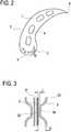
1 eine Längsschnittansicht einer Schaufel nach einer Ausführungsform der vorliegenden Erfindung;2 eine QuerschnittansichtA-A der Schaufel der1 ;3 eine SchnittansichtB-B der Schaufel der1 ; und4 verschiedene SchnittansichtenI undII der Schaufel der1 .
1 a longitudinal sectional view of a blade according to an embodiment of the present invention;2 a cross-sectional viewAA the scoop of the1 ;3 a sectional viewBB the scoop of the1 ; and4 different sectional viewsI andII the scoop of the1 ,
Vorzugsweise weisen die Kühlkanäle
Vorzugsweise verlaufen die Kühlkanäle mindestens über 50%, vorzugsweise mindestens über 70%, weiter bevorzugt mindestens über 90% ihrer Länge in einem Abstand A zur Schaufellänge, der in einem Bereich von 0,1·Dmax ≤ A ≤ 3·Dmax, vorzugsweise 0,5·Dmax ≤ A ≤ 3·Dmax, weiter bevorzugt Dmax ≤ A ≤ 2·Dmax, liegt, wobei Dmax jeweils entweder das maximale Querschnittsmaß oder ein hydraulischer Durchmesser eines Kühlkanals
Vorzugsweise sind die Kühlkanäle
In der dargestellten Ausführungsform münden die Kühlkanäle
Um sicherzustellen, dass ausreichend Kühlluft in die Kühlkanäle
Die Wärmekonvektion kann hierbei als Wärmeaustrag bzw. Wärmestrom pro Flächeneinheit mit der Einheit J / (s·m2) oder W / m2 gemessen werden. Durch die unterschiedlichen Abstände
In der dargestellten Ausführungsform ändert sich ein Abstand zwischen mindestens zwei benachbarten Kühlkanälen
Die Kühlkanäle
Daneben gibt es weitere Möglichkeiten, die Wärmekonvektion räumlich zu variieren. Zumindest ein Kühlkanal
Durch Verkleinern des Abstands der Kühlkanäle
das Volumen des Kühlmediums lokal vergrößert werden. Dadurch kann mehr Wärme im Bereich mit vergrößertem Querschnittsflächeninhalt ausgetragen werden.the volume of the cooling medium can be increased locally. As a result, more heat in the area can be discharged with increased cross-sectional area.
Durch Vergrößern der Rauigkeit der Innenfläche der Kühlkanäle
Die Querschnittsform kann zwischen kreisrunden, elliptischen, eckigen oder beliebigen anderen Formen variiert werden. Zum Beispiel kann durch eine elliptische Form, wenn deren Hauptachse im Wesentlichen parallel zur Oberfläche
Der geometrische Verlauf der Kühlkanäle
Es kann auch eine Erhebung oder eine Sicke in den Kühlkanälen
Besonders gute Wärmekonvektionen können erhalten werden, wenn die Kühlkanäle
Anders als beim Stand der Technik verlaufen die Kühlkanäle
Die Kühlkanäle
In der dargestellten Ausführungsform erfolgt die Kühlung der Schaufel ausschließlich durch Wärmekonvektion, d.h. das Kühlmedium in den Kühlkanälen
In einer Abwandlung sieht die vorliegende Erfindung eine Mischform vor, bei der die Kühlkanäle
Vorzugsweise wird die Schaufel zumindest bereichsweise oder vollständig durch ein additives Herstellungsverfahren hergestellt. Dadurch können insbesondere die filigranen Kühlkanäle
Obwohl in der vorhergehenden Beschreibung exemplarische Ausführungen erläutert wurden, sei darauf hingewiesen, dass eine Vielzahl von Abwandlungen möglich ist. Außerdem sei darauf hingewiesen, dass es sich bei den exemplarischen Ausführungen lediglich um Beispiele handelt, die den Schutzbereich, die Anwendungen und den Aufbau in keiner Weise einschränken sollen. Vielmehr wird dem Fachmann durch die vorausgehende Beschreibung ein Leitfaden für die Umsetzung von mindestens einer exemplarischen Ausführung gegeben, wobei diverse Änderungen, insbesondere in Hinblick auf die Funktion und Anordnung der beschriebenen Bestandteile, vorgenommen werden können, ohne den Schutzbereich zu verlassen, wie er sich aus den Ansprüchen und diesen äquivalenten Merkmalskombinationen ergibt.Although exemplary embodiments have been explained in the foregoing description, it should be understood that a variety of modifications are possible. It should also be noted that the exemplary embodiments are merely examples that are not intended to limit the scope, applications and construction in any way. Rather, the expert is given by the preceding description, a guide for the implementation of at least one exemplary embodiment, with various changes, in particular with regard to the function and arrangement of the components described, can be made without departing from the scope, as it turns out according to the claims and these equivalent combinations of features.
BezugszeichenlisteLIST OF REFERENCE NUMBERS
- 11
- Schaufelshovel
- 22
- Oberflächesurface
- 33
- Kühlkanalcooling channel
- 44
- Hauptkanalmain channel
- 55
- Vorderkanteleading edge
- 66
- Hinterkantetrailing edge
- 77
- Engstellebottleneck
- 3131
- KühlkanalabschnittCooling duct section
- 3232
- KühlkanalabschnittCooling duct section
- 3333
- KühlkanalabschnittCooling duct section
- 3434
- KühlkanalabschnittCooling duct section
ZITATE ENTHALTEN IN DER BESCHREIBUNG QUOTES INCLUDE IN THE DESCRIPTION
Diese Liste der vom Anmelder aufgeführten Dokumente wurde automatisiert erzeugt und ist ausschließlich zur besseren Information des Lesers aufgenommen. Die Liste ist nicht Bestandteil der deutschen Patent- bzw. Gebrauchsmusteranmeldung. Das DPMA übernimmt keinerlei Haftung für etwaige Fehler oder Auslassungen.This list of the documents listed by the applicant has been generated automatically and is included solely for the better information of the reader. The list is not part of the German patent or utility model application. The DPMA assumes no liability for any errors or omissions.
Zitierte PatentliteraturCited patent literature
- US 20160208705 A1 [0005]US 20160208705 A1 [0005]
- US 20150322800 A1 [0005]US 20150322800 A1 [0005]
- DE 102015015598 A1 [0006]DE 102015015598 A1 [0006]
- EP 3056670 A1 [0006]EP 3056670 A1 [0006]
- WO 2015175168 A1 [0006]WO 2015175168 A1 [0006]
Claims (15)
Translated fromGermanPriority Applications (1)
| Application Number | Priority Date | Filing Date | Title |
|---|---|---|---|
| DE102018205721.4ADE102018205721A1 (en) | 2018-04-16 | 2018-04-16 | Blade for a turbomachine and use and manufacturing method thereof |
Applications Claiming Priority (1)
| Application Number | Priority Date | Filing Date | Title |
|---|---|---|---|
| DE102018205721.4ADE102018205721A1 (en) | 2018-04-16 | 2018-04-16 | Blade for a turbomachine and use and manufacturing method thereof |
Publications (1)
| Publication Number | Publication Date |
|---|---|
| DE102018205721A1true DE102018205721A1 (en) | 2019-10-17 |
Family
ID=68052848
Family Applications (1)
| Application Number | Title | Priority Date | Filing Date |
|---|---|---|---|
| DE102018205721.4AWithdrawnDE102018205721A1 (en) | 2018-04-16 | 2018-04-16 | Blade for a turbomachine and use and manufacturing method thereof |
Country Status (1)
| Country | Link |
|---|---|
| DE (1) | DE102018205721A1 (en) |
Cited By (1)
| Publication number | Priority date | Publication date | Assignee | Title |
|---|---|---|---|---|
| WO2024041970A1 (en)* | 2022-08-24 | 2024-02-29 | Siemens Energy Global GmbH & Co. KG | Turbine vane for a gas turbine |
Citations (9)
| Publication number | Priority date | Publication date | Assignee | Title |
|---|---|---|---|---|
| US8444386B1 (en)* | 2010-01-19 | 2013-05-21 | Florida Turbine Technologies, Inc. | Turbine blade with multiple near wall serpentine flow cooling |
| US20150147164A1 (en)* | 2013-11-22 | 2015-05-28 | General Electric Company | Modified turbine components with internally cooled supplemental elements and methods for making the same |
| US20150322800A1 (en) | 2014-05-12 | 2015-11-12 | Honeywell International Inc. | Gas path components of gas turbine engines and methods for cooling the same using porous medium cooling systems |
| WO2015175168A1 (en) | 2014-05-12 | 2015-11-19 | Siemens Energy, Inc. | Laser deposition of metal foam |
| DE102015015598A1 (en) | 2014-12-16 | 2016-06-16 | Rolls-Royce Plc | Cooling of engine components |
| US20160208705A1 (en) | 2013-10-30 | 2016-07-21 | United Technologies Corporation | Bore-cooled film dispensing pedestals |
| EP3056670A1 (en) | 2015-02-11 | 2016-08-17 | United Technologies Corporation | Turbomachine component having cooling channels with angled pedestals |
| EP3401506A2 (en)* | 2017-05-11 | 2018-11-14 | General Electric Company | Cmc components having microchannels and methods for forming microchannels in cmc components |
| EP3409890A1 (en)* | 2017-05-31 | 2018-12-05 | General Electric Company | Component for use in a hot gas path of an industrial machine |
- 2018
- 2018-04-16DEDE102018205721.4Apatent/DE102018205721A1/ennot_activeWithdrawn
Patent Citations (9)
| Publication number | Priority date | Publication date | Assignee | Title |
|---|---|---|---|---|
| US8444386B1 (en)* | 2010-01-19 | 2013-05-21 | Florida Turbine Technologies, Inc. | Turbine blade with multiple near wall serpentine flow cooling |
| US20160208705A1 (en) | 2013-10-30 | 2016-07-21 | United Technologies Corporation | Bore-cooled film dispensing pedestals |
| US20150147164A1 (en)* | 2013-11-22 | 2015-05-28 | General Electric Company | Modified turbine components with internally cooled supplemental elements and methods for making the same |
| US20150322800A1 (en) | 2014-05-12 | 2015-11-12 | Honeywell International Inc. | Gas path components of gas turbine engines and methods for cooling the same using porous medium cooling systems |
| WO2015175168A1 (en) | 2014-05-12 | 2015-11-19 | Siemens Energy, Inc. | Laser deposition of metal foam |
| DE102015015598A1 (en) | 2014-12-16 | 2016-06-16 | Rolls-Royce Plc | Cooling of engine components |
| EP3056670A1 (en) | 2015-02-11 | 2016-08-17 | United Technologies Corporation | Turbomachine component having cooling channels with angled pedestals |
| EP3401506A2 (en)* | 2017-05-11 | 2018-11-14 | General Electric Company | Cmc components having microchannels and methods for forming microchannels in cmc components |
| EP3409890A1 (en)* | 2017-05-31 | 2018-12-05 | General Electric Company | Component for use in a hot gas path of an industrial machine |
Non-Patent Citations (1)
| Title |
|---|
| MAGERRAAMOVA, Liubov; VASILYEV, Boris; KINZBURSKIY, Vladimir: Novel designs of turbine blades for additive manufacturing. In: Proceedings of ASME Turbo Expo 2016: Turbomachinery Technical Conference and Exposition, 13-17 June 2016, Seoul, South Korea. 2016, GT2016-56084, S. 1-8. - ISBN 978-0-7918-4980-4.* |
Cited By (1)
| Publication number | Priority date | Publication date | Assignee | Title |
|---|---|---|---|---|
| WO2024041970A1 (en)* | 2022-08-24 | 2024-02-29 | Siemens Energy Global GmbH & Co. KG | Turbine vane for a gas turbine |
Similar Documents
| Publication | Publication Date | Title |
|---|---|---|
| DE60018817T2 (en) | Chilled gas turbine blade | |
| DE69932688T2 (en) | Cooling openings for gas turbine components | |
| EP2737178B1 (en) | Method for producing, repairing and/or exchanging an engine housing, and a corresponding housing | |
| DE60017437T2 (en) | RIBS FOR INCREASING THE HEAT TRANSFER OF A COOLING AIR INNER COOLED TURBINE BLADE | |
| DE69823236T2 (en) | DEVICE FOR COOLING GAS TURBINE SHOVELS AND METHOD FOR THE PRODUCTION THEREOF | |
| DE1476796C3 (en) | A component of a gas turbine system made integrally from a high-strength material | |
| EP3191244B1 (en) | Method for manufacturing a rotor blade and blade obtained thereby | |
| DE102011053930B4 (en) | Device and method for cooling platform sections of turbine rotor blades | |
| EP3183497B1 (en) | Heat shield element and method for the production thereof | |
| EP3298242A1 (en) | Blade for a turbo engine and method for manufacturing same | |
| DE102015219530A1 (en) | Blade for a turbomachine, turbofan engine and a method for producing a blade | |
| DE112020000789B4 (en) | HIGH TEMPERATURE COMPONENT AND METHOD FOR PRODUCING THE HIGH TEMPERATURE COMPONENT | |
| DE102014111837A1 (en) | Gas turbine components with porous cooling features | |
| DE102016122313A1 (en) | Article and method of making an article | |
| DE102014100482A1 (en) | Hot gas path component for turbine system | |
| DE102017110050A1 (en) | Exploded central recess behind the sash leading edge | |
| DE102019132728A1 (en) | TURBINE SHOVEL TIP COOLING SYSTEM WITH TIP RAIL COOLING INSERT | |
| DE102018131044A1 (en) | Turbine component with a top rail cooling duct | |
| EP2199725A1 (en) | Multi-impingement-surface for cooling a wall | |
| DE102017110051A1 (en) | Bucket with load-reducing bulbous projection on a turning opening of coolant channels | |
| EP3456923A1 (en) | Blade of a turbomachine having cooling passage and displacement body arranged therein and method for producing the same | |
| DE102012104240B4 (en) | Hybrid Flow Blade Designs | |
| DE102018205721A1 (en) | Blade for a turbomachine and use and manufacturing method thereof | |
| DE102017110052A1 (en) | Inner rib with defined concave surface curvature for an airfoil | |
| EP1512911B1 (en) | Device for cooling high-thermally stressed parts |
Legal Events
| Date | Code | Title | Description |
|---|---|---|---|
| R163 | Identified publications notified | ||
| R119 | Application deemed withdrawn, or ip right lapsed, due to non-payment of renewal fee |