DE102018203344A1 - Interaction module - Google Patents
Interaction moduleDownload PDFInfo
- Publication number
- DE102018203344A1 DE102018203344A1DE102018203344.7ADE102018203344ADE102018203344A1DE 102018203344 A1DE102018203344 A1DE 102018203344A1DE 102018203344 ADE102018203344 ADE 102018203344ADE 102018203344 A1DE102018203344 A1DE 102018203344A1
- Authority
- DE
- Germany
- Prior art keywords
- interaction module
- projector
- work surface
- scanning device
- image
- Prior art date
- Legal status (The legal status is an assumption and is not a legal conclusion. Google has not performed a legal analysis and makes no representation as to the accuracy of the status listed.)
- Pending
Links
Images


Classifications
- F—MECHANICAL ENGINEERING; LIGHTING; HEATING; WEAPONS; BLASTING
- F24—HEATING; RANGES; VENTILATING
- F24C—DOMESTIC STOVES OR RANGES ; DETAILS OF DOMESTIC STOVES OR RANGES, OF GENERAL APPLICATION
- F24C7/00—Stoves or ranges heated by electric energy
- F24C7/08—Arrangement or mounting of control or safety devices
- G—PHYSICS
- G06—COMPUTING OR CALCULATING; COUNTING
- G06F—ELECTRIC DIGITAL DATA PROCESSING
- G06F3/00—Input arrangements for transferring data to be processed into a form capable of being handled by the computer; Output arrangements for transferring data from processing unit to output unit, e.g. interface arrangements
- G06F3/01—Input arrangements or combined input and output arrangements for interaction between user and computer
- G06F3/03—Arrangements for converting the position or the displacement of a member into a coded form
- G06F3/041—Digitisers, e.g. for touch screens or touch pads, characterised by the transducing means
- G06F3/042—Digitisers, e.g. for touch screens or touch pads, characterised by the transducing means by opto-electronic means
- G06F3/0425—Digitisers, e.g. for touch screens or touch pads, characterised by the transducing means by opto-electronic means using a single imaging device like a video camera for tracking the absolute position of a single or a plurality of objects with respect to an imaged reference surface, e.g. video camera imaging a display or a projection screen, a table or a wall surface, on which a computer generated image is displayed or projected
Landscapes
- Engineering & Computer Science (AREA)
- General Engineering & Computer Science (AREA)
- Theoretical Computer Science (AREA)
- Human Computer Interaction (AREA)
- Physics & Mathematics (AREA)
- General Physics & Mathematics (AREA)
- Multimedia (AREA)
- Chemical & Material Sciences (AREA)
- Combustion & Propulsion (AREA)
- Mechanical Engineering (AREA)
- Projection Apparatus (AREA)
- Position Input By Displaying (AREA)
- Transforming Electric Information Into Light Information (AREA)
Abstract
Translated fromGerman
Description
Translated fromGermanDie Erfindung betrifft ein Interaktionsmodul. Insbesondere betrifft die Erfindung ein Interaktionsmodul zur Steuerung eines Geräts mittels einer Geste bezüglich eines auf eine Arbeitsfläche projizierten Bilds.The invention relates to an interaction module. In particular, the invention relates to an interaction module for controlling a device by means of a gesture with respect to an image projected onto a work surface.
Ein Interaktionsmodul ist dazu eingerichtet, ein Bild auf eine Arbeitsfläche zu projizieren und eine Geste eines Benutzers bezüglich des Bildes auszuwerten. Dazu umfasst das Interaktionsmodul einen Projektor und eine optische Abtasteinrichtung. Das Bild kann insbesondere die Darstellung einer Schaltfläche oder eines ähnlichen Elements umfassen. Berührt der Benutzer die Schaltfläche, etwa mit einem Finger, so kann eine vorbestimmte Steuerung ausgelöst werden. Beispielsweise können ein Gerät im Bereich der Arbeitsfläche oder eine Beleuchtung ein- oder ausgeschaltet werden. Das Interaktionsmodul kann in einem Haushalt, insbesondere in einer Küche verwendet werden. Dabei können auch andere Darstellungen als die Schaltfläche auf die Arbeitsfläche projiziert werden, beispielsweise ein geschriebenes Rezept oder ein Videostrom.An interaction module is arranged to project an image onto a work surface and to evaluate a gesture of a user with respect to the image. For this purpose, the interaction module comprises a projector and an optical scanning device. In particular, the image may include the appearance of a button or similar element. When the user touches the button, say with a finger, a predetermined control can be triggered. For example, a device in the area of the work surface or a lighting can be switched on or off. The interaction module can be used in a household, especially in a kitchen. In this case, other representations than the button can be projected onto the desktop, such as a written recipe or a video stream.
Hält der Benutzer beim Annähern an die Schaltfläche seinen Finger steil, sodass er einen großen Winkel mit der Arbeitsfläche einschließt, so kann er aus der Perspektive des Interaktionsmoduls die Schaltfläche teilweise verschatten, sodass es schwierig sein kann, das Berühren der Schaltfläche genau zu bestimmen.When the user approaches the button, keeping his / her finger steep so that it encloses a large angle with the work surface, it may partially obscure the button from the perspective of the interaction module, so that it may be difficult to pinpoint the touching of the button.
Eine der vorliegenden Erfindung zu Grunde liegende Aufgabe besteht darin, ein Interaktionsmodul anzugeben, das ein verlässliches Bestimmen einer Berührung der Arbeitsplatte im Bereich eines projizierten Bildes unterstützt. Die Erfindung löst diese Aufgabe mittels des Gegenstands des unabhängigen Anspruchs. Unteransprüche geben bevorzugte Ausführungsformen wieder.An object underlying the present invention is to provide an interaction module which assists reliable determination of a touch of the work surface in the area of a projected image. The invention achieves this object by means of the subject matter of the independent claim. Subclaims give preferred embodiments again.
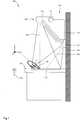
Ein Interaktionsmodul umfasst einen Projektor, der zur Projektion eines Bildes auf eine Arbeitsfläche eingerichtet ist; und eine optische Abtasteinrichtung, die zur Bestimmung einer Geste eines Benutzers in einem Bereich des projizierten Bildes zwischen dem Projektor und der Arbeitsfläche eingerichtet ist. Dabei schließen optische Achsen des Projektors und der Abtasteinrichtung im Bereich der Arbeitsfläche einen Winkel ≥ 5° miteinander ein.An interaction module includes a projector configured to project an image onto a work surface; and an optical pickup configured to determine a gesture of a user in an area of the projected image between the projector and the work surface. In this case, optical axes of the projector and the scanning device in the area of the work surface an angle ≥ 5 ° with each other.
Das Interaktionsmodul ist üblicherweise über der Arbeitsfläche angebracht. Die optische Achse des Projektors ist üblicherweise durch eine Optik vorgegeben, durch die ein Lichtbündel fällt, das auf der Arbeitsfläche als Bild wahrgenommen werden kann. Das Lichtbündel kann symmetrisch zur optischen Achse liegen, in diesem Fall entspricht die optische Achse der Verbindung einer Mitte eines Lichtaustrittsbereichs zu einer Mitte des Bildbereichs. Das Lichtbündel kann aber auch in einer oder zwei Richtungen asymmetrisch zur optischen Achse des Projektors liegen. Die optische Achse der Abtasteinrichtung ist üblicherweise durch dessen Optik vorgegeben. Umfasst die Abtasteinrichtung nur einen optischen Sensor, so kann dessen optische Achse verwendet werden. Umfasst die Abtasteinrichtung zwei zueinander versetzte Sensoren, so kann eine Mittellinie zwischen optischen Achsen der Sensoren als optische Achse der Abtasteinrichtung angesehen werden. Eine optische Achse einer möglichen dedizierten Beleuchtungseinrichtung der Abtasteinrichtung kann hingegen unmaßgeblich sein. Eine solche Beleuchtungseinrichtung kann insbesondere nicht sichtbares Licht aussenden, das von den Sensoren abgetastet werden kann. Diesem Licht kann eine Struktur aufgeprägt sein, beispielsweise ein Punkt- oder Streifenmuster.The interaction module is usually mounted above the work surface. The optical axis of the projector is usually given by an optical system, through which a light beam falls, which can be perceived as an image on the work surface. The light beam may be symmetrical to the optical axis, in which case the optical axis corresponds to the connection of a center of a light exit area to a center of the image area. However, the light beam can also be asymmetrical in one or two directions to the optical axis of the projector. The optical axis of the scanning device is usually predetermined by its optics. If the scanning device comprises only one optical sensor, its optical axis can be used. If the scanning device comprises two mutually offset sensors, a center line between the optical axes of the sensors can be regarded as the optical axis of the scanning device. On the other hand, an optical axis of a possible dedicated illumination device of the scanning device can be irrelevant. Such a lighting device can in particular emit non-visible light that can be scanned by the sensors. This structure may be imprinted with a structure, such as a dot or stripe pattern.
Durch den gegenüber dem Stand der Technik vergrößerten Winkel kann ein Zeitpunkt, wenn eine Geste bezüglich der Arbeitsfläche eintritt, insbesondere der Zeitpunkt der Berührung eines vorbestimmten Abschnitts der Arbeitsfläche, auch dann genau bestimmt werden, wenn das Objekt, mit dem die Geste vollführt wird, etwa ein Finger eines Benutzers, so gehalten wird, dass die berührte Stelle bezüglich des Projektors verdeckt ist. Dies kann beispielsweise der Fall sein, wenn der Benutzer seinen Finger steil hält, sodass der Abschnitt des Fingers, welcher der Arbeitsfläche am nächsten liegt, vom Projektor aus nicht sichtbar ist.Due to the increased angle compared to the prior art, a time when a gesture with respect to the work surface occurs, in particular the time of contact of a predetermined portion of the work surface, even be determined accurately when the object with which the gesture is performed, about a user's finger is held so that the touched point is obscured with respect to the projector. This may be the case, for example, when the user holds his finger sharply, so that the portion of the finger closest to the work surface is not visible from the projector.
Die optische Achse des Projektors kann mit einer Senkrechten auf die Arbeitsfläche einen Winkel ≤ 20° einschließen. Durch den steilen Projektionswinkel kann das Bild verzerrungsarm auf der Arbeitsfläche angezeigt werden. Eine unbeabsichtigte Verschattung eines Teils des Bildes durch ein auf der Arbeitsfläche liegendes Objekt kann reduziert sein. Außerdem kann der Projektor außerhalb eines Bewegungsbereichs eines Benutzers liegen, der an der Arbeitsfläche steht.The optical axis of the projector may include an angle ≤ 20 ° with a perpendicular to the work surface. Due to the steep projection angle, the image can be displayed distortion-free on the work surface. Unintentional shading of a part of the image by an object lying on the work surface can be reduced. In addition, the projector may be outside a range of motion of a user standing at the work surface.
Der Projektor und die Abtasteinrichtung sind bevorzugt in einem gemeinsamen Gehäuse angebracht. Dadurch kann das Interaktionsmodul verbessert gegenüber Verschmutzung geschützt oder wartungsfreundlich gekapselt werden. Eine Kommunikation oder Energieübertragung zwischen Komponenten des Interaktionsmoduls kann vereinfacht sein.The projector and the scanner are preferably mounted in a common housing. As a result, the interaction module can be better protected against contamination or encapsulated in a way that is easy to maintain. Communication or energy transfer between components of the interaction module can be simplified.
Um den geforderten Winkel von ≥ 5° zwischen den optischen Achsen einzuhalten kann das Gehäuse groß genug sein, um einen ausreichenden Abstand zwischen dem Projektor und der Abtasteinrichtung zu ermöglichen. In einer anderen Ausführungsform können die optischen Achsen des Projektors und der Abtasteinrichtung im Bereich des Gehäuses in Richtung der Arbeitsfläche auseinanderlaufen. Entweder das vom Projektor ausgesandte Lichtbündel oder das von der Abtasteinrichtung registrierte Licht kann zwischen dem Bereich des Bildes und dem Interaktionsmodul umgelenkt werden.In order to maintain the required angle of ≥ 5 ° between the optical axes, the Housing be large enough to allow sufficient distance between the projector and the scanner. In another embodiment, the optical axes of the projector and the scanning device in the region of the housing can diverge in the direction of the work surface. Either the light beam emitted by the projector or the light registered by the scanner can be redirected between the area of the image and the interaction module.
Die optische Achse der Abtasteinrichtung ist bevorzugt derart gerichtet, dass ein Umlenkelement, das zur Umlenkung von Licht zwischen der Arbeitsfläche und der Abtasteinrichtung eingerichtet ist, senkrecht zur Arbeitsfläche angebracht sein kann.The optical axis of the scanning device is preferably directed such that a deflecting element, which is set up to deflect light between the working surface and the scanning device, can be mounted perpendicular to the working surface.
Die Umlenkung kann insbesondere mittels einer reflektierenden Fläche erfolgen, die sich in im Wesentlichen vertikaler Richtung zwischen dem Interaktionsmodul und der Arbeitsfläche erstreckt. Eine solche Fläche kann beispielsweise durch einen Fliesenspiegel oder eine Glasplatte realisiert sein. Derartige reflektierende vertikale Flächen werden häufig in Küchen verwendet, um beispielsweise eine Wand vor Verschmutzung zu schützen und eine leichte Reinigung zu erlauben. In vielen Fällen ist eine solche Fläche im Bereich eines Herdes zu finden, von dem beim Kochen beispielsweise Wasserdampf oder Fettspritzer ausgehen können.The deflection may in particular be effected by means of a reflecting surface which extends in a substantially vertical direction between the interaction module and the working surface. Such a surface can be realized for example by a tile mirror or a glass plate. Such reflective vertical surfaces are often used in kitchens, for example to protect a wall from soiling and to allow easy cleaning. In many cases, such an area can be found in the area of a stove from which, for example, water vapor or fat splashes can be emitted during cooking.
Durch das Ausnutzen einer bereits vorhandenen reflektierenden Fläche kann das Interaktionsmodul elegant und hygienisch in eine bestehende Arbeitsanordnung, insbesondere in einer Küche, eingebaut werden. Das Interaktionsmodul selbst kann kompakt aufgebaut sein und nur wenig wertvollen Platz im Bereich der Küche einnehmen.By exploiting an existing reflective surface, the interaction module can be installed elegantly and hygienically in an existing work arrangement, in particular in a kitchen. The interaction module itself can be compact and take up little valuable space in the kitchen area.
Das Interaktionsmodul kann das Umlenkelement umfassen. Beispielsweise kann das Umlenkelement innerhalb des Gehäuses angebracht sein. In einer anderen Ausführungsform kann sich das reflektierende Element in vertikaler Richtung von dem Gehäuse aus erstrecken. Dabei kann das reflektierende Element dazu eingerichtet sein, an einer vertikalen Fläche zwischen dem Interaktionsmodul und der Arbeitsfläche flächig anzuliegen. Dadurch kann das reflektierende Element verbessert geschützt sein. Außerdem kann es so leichter sauber gehalten bzw. gereinigt werden.The interaction module may comprise the deflection element. For example, the deflecting element may be mounted inside the housing. In another embodiment, the reflective element may extend in a vertical direction from the housing. In this case, the reflective element can be set up to lie flat on a vertical surface between the interaction module and the work surface. As a result, the reflective element can be better protected. It also makes it easier to keep clean or clean.
Insbesondere kann das Umlenkelement am Gehäuse des Interaktionsmoduls angebracht sein. Das Interaktionsmodul kann dadurch weniger zerklüftet ausgeführt sein, was die Reinigungsfähigkeit weiter verbessern kann.In particular, the deflecting element may be attached to the housing of the interaction module. The interaction module can thereby be made less rugged, which can further improve the cleaning ability.
Es ist bevorzugt, dass ein Abtastbereich der Abtasteinrichtung im Bereich der Arbeitsfläche die gesamte Bildfläche umfasst. Dadurch kann gerade derjenige Bereich abgetastet werden, auf dem mittels des Projektors ein Bedien- oder Schaltelement dargestellt werden kann. Ein „blinder“ Bereich, in welchem das Bild angezeigt werden kann, ohne eine korrespondierende Geste abtasten zu können, kann so vermieden werden.It is preferred that a scanning region of the scanning device in the region of the working surface comprises the entire image surface. As a result, it is possible to scan the area on which an operating or switching element can be displayed by means of the projector. A "blind" area in which the image can be displayed without being able to scan a corresponding gesture can thus be avoided.
Das Interaktionsmodul kann ferner eine Verarbeitungseinrichtung umfassen, die dazu eingerichtet ist, eine Geste bezüglich eines Abschnitts des Bildes zu bestimmen und in Abhängigkeit der Geste und des Abschnitts eine vorbestimmte Steuerfunktion auszulösen. Die Steuerfunktion kann das Interaktionsmodul betreffen, beispielsweise indem eine optische Ausgabe des Bildes verändert wird, oder eine Funktion an einem anderen Gerät auslösen. Das andere Gerät kann insbesondere im Bereich der Arbeitsfläche angeordnet sein und umfasst weiter bevorzugt ein Küchengerät wie einen Herd, einen Ofen, eine Dunstabzugshaube oder eine Beleuchtung.The interaction module may further comprise processing means arranged to determine a gesture with respect to a portion of the image and to trigger a predetermined control function in response to the gesture and the portion. The control function may affect the interaction module, for example by changing an optical output of the image, or triggering a function on another device. The other device can be arranged in particular in the area of the work surface and more preferably comprises a kitchen appliance such as a stove, an oven, an extractor hood or a lighting.
Die Erfindung wird nun unter Bezug auf die beiliegenden Figuren genauer beschrieben, in denen:
1 ein erstes beispielhaftes System mit einem Interaktionsmodul;2 ein zweites beispielhaftes System mit einem Interaktionsmodul; und3 das System von2 in einer weiteren Ausführungsform darstellt.
1 a first exemplary system with an interaction module;2 a second exemplary system with an interaction module; and3 the system of2 in a further embodiment.
Zur leichteren Bezugnahme ist ein beispielhaftes Koordinatensystem angegeben. Eine Breitenrichtung (
Das System
Das Interaktionsmodul
In der dargestellten Ausführungsform ist das Interaktionsmodul
Die beiden Teile des Interaktionsmoduls
Ein Winkel
Die Abtasteinrichtung
Die reflektierende Fläche kann beispielsweise durch einen Fliesenspiegel, eine Glas- oder Edelstahlplatte realisiert sein, die beispielsweise an der Wand
Reflektionseigenschaften des Umlenkelements
BezugszeichenlisteLIST OF REFERENCE NUMBERS
- 100100
- Systemsystem
- 105105
- InteraktionsmodulInteraction module
- 110110
- Bildimage
- 115115
- Arbeitsflächeworking surface
- 120120
- Fingerfinger
- 125125
- Benutzerpositionuser location
- 130130
- Gerät, MöbelDevice, furniture
- 135135
- Wandwall
- 140140
- Projektorprojector
- 145145
- optische Abtasteinrichtungoptical scanning device
- 150150
- Gehäusecasing
- 155155
- Verarbeitungseinrichtungprocessing device
- 160160
- optische Achse des Projektorsoptical axis of the projector
- 165165
- optische Achse der Abtasteinrichtungoptical axis of the scanner
- xx
- Breitenrichtungwidth direction
- yy
- Tiefenrichtungdepth direction
- zz
- Höhenrichtungheight direction
- 305305
- reflektierende Fläche, Umlenkelementreflective surface, deflection element
ZITATE ENTHALTEN IN DER BESCHREIBUNG QUOTES INCLUDE IN THE DESCRIPTION
Diese Liste der vom Anmelder aufgeführten Dokumente wurde automatisiert erzeugt und ist ausschließlich zur besseren Information des Lesers aufgenommen. Die Liste ist nicht Bestandteil der deutschen Patent- bzw. Gebrauchsmusteranmeldung. Das DPMA übernimmt keinerlei Haftung für etwaige Fehler oder Auslassungen.This list of the documents listed by the applicant has been generated automatically and is included solely for the better information of the reader. The list is not part of the German patent or utility model application. The DPMA assumes no liability for any errors or omissions.
Zitierte PatentliteraturCited patent literature
- DE 102009000653 B4 [0003]DE 102009000653 B4 [0003]
Claims (9)
Translated fromGermanPriority Applications (2)
| Application Number | Priority Date | Filing Date | Title |
|---|---|---|---|
| DE102018203344.7ADE102018203344A1 (en) | 2018-03-07 | 2018-03-07 | Interaction module |
| PCT/EP2019/054537WO2019170451A1 (en) | 2018-03-07 | 2019-02-25 | Interaction module |
Applications Claiming Priority (1)
| Application Number | Priority Date | Filing Date | Title |
|---|---|---|---|
| DE102018203344.7ADE102018203344A1 (en) | 2018-03-07 | 2018-03-07 | Interaction module |
Publications (1)
| Publication Number | Publication Date |
|---|---|
| DE102018203344A1true DE102018203344A1 (en) | 2019-09-12 |
Family
ID=65657439
Family Applications (1)
| Application Number | Title | Priority Date | Filing Date |
|---|---|---|---|
| DE102018203344.7APendingDE102018203344A1 (en) | 2018-03-07 | 2018-03-07 | Interaction module |
Country Status (2)
| Country | Link |
|---|---|
| DE (1) | DE102018203344A1 (en) |
| WO (1) | WO2019170451A1 (en) |
Cited By (1)
| Publication number | Priority date | Publication date | Assignee | Title |
|---|---|---|---|---|
| EP3954250A1 (en)* | 2020-08-12 | 2022-02-16 | Richard Loch | Kitchen furniture assembly with projection device for projecting an image onto a projection surface |
Citations (5)
| Publication number | Priority date | Publication date | Assignee | Title |
|---|---|---|---|---|
| DE102008060363A1 (en)* | 2008-12-03 | 2010-06-10 | GM Global Technology Operations, Inc., Detroit | Operating system for motor vehicle, has projection device for graphical reproduction of display elements on display surface, where control action of operating elements is detectable by detection of minimum pressure exerted on surface |
| DE102009000653B4 (en) | 2009-02-06 | 2011-03-17 | BSH Bosch und Siemens Hausgeräte GmbH | Method and device for operating at least one household appliance |
| DE102013200372A1 (en)* | 2013-01-14 | 2014-07-17 | BSH Bosch und Siemens Hausgeräte GmbH | Hob, kitchen counter with integrated hob and kitchenette |
| US20140313122A1 (en)* | 2013-04-18 | 2014-10-23 | Fuji Xerox Co., Ltd. | Systems and methods for enabling gesture control based on detection of occlusion patterns |
| DE102014007704A1 (en)* | 2014-05-22 | 2015-11-26 | Andreas Obrebski | Optical extension for a smartphone camera |
Family Cites Families (3)
| Publication number | Priority date | Publication date | Assignee | Title |
|---|---|---|---|---|
| GB9614837D0 (en)* | 1996-07-12 | 1996-09-04 | Rank Xerox Ltd | Interactive desktop system with multiple image capture and display modes |
| GB2486445B (en)* | 2010-12-14 | 2013-08-14 | Epson Norway Res And Dev As | Camera-based multi-touch interaction apparatus system and method |
| JP5941146B2 (en)* | 2011-07-29 | 2016-06-29 | ヒューレット−パッカード デベロップメント カンパニー エル.ピー.Hewlett‐Packard Development Company, L.P. | Projection capture system, program and method |
- 2018
- 2018-03-07DEDE102018203344.7Apatent/DE102018203344A1/enactivePending
- 2019
- 2019-02-25WOPCT/EP2019/054537patent/WO2019170451A1/ennot_activeCeased
Patent Citations (5)
| Publication number | Priority date | Publication date | Assignee | Title |
|---|---|---|---|---|
| DE102008060363A1 (en)* | 2008-12-03 | 2010-06-10 | GM Global Technology Operations, Inc., Detroit | Operating system for motor vehicle, has projection device for graphical reproduction of display elements on display surface, where control action of operating elements is detectable by detection of minimum pressure exerted on surface |
| DE102009000653B4 (en) | 2009-02-06 | 2011-03-17 | BSH Bosch und Siemens Hausgeräte GmbH | Method and device for operating at least one household appliance |
| DE102013200372A1 (en)* | 2013-01-14 | 2014-07-17 | BSH Bosch und Siemens Hausgeräte GmbH | Hob, kitchen counter with integrated hob and kitchenette |
| US20140313122A1 (en)* | 2013-04-18 | 2014-10-23 | Fuji Xerox Co., Ltd. | Systems and methods for enabling gesture control based on detection of occlusion patterns |
| DE102014007704A1 (en)* | 2014-05-22 | 2015-11-26 | Andreas Obrebski | Optical extension for a smartphone camera |
Non-Patent Citations (1)
| Title |
|---|
| WILSON, A. D.: PlayAnywhere: A Compact Interactive Tabletop Projection-Vision System. In: Proceedings of the 18th annual ACM symposium on User interface software and technology. ACM, 2005, S. 83-92.* |
Cited By (2)
| Publication number | Priority date | Publication date | Assignee | Title |
|---|---|---|---|---|
| EP3954250A1 (en)* | 2020-08-12 | 2022-02-16 | Richard Loch | Kitchen furniture assembly with projection device for projecting an image onto a projection surface |
| DE102020121261A1 (en) | 2020-08-12 | 2022-02-17 | Richard Loch | Kitchen furniture arrangement with a projection device for projecting an image onto a projection surface |
Also Published As
| Publication number | Publication date |
|---|---|
| WO2019170451A1 (en) | 2019-09-12 |
Similar Documents
| Publication | Publication Date | Title |
|---|---|---|
| DE69926908T2 (en) | SYSTEM FOR CONTRASTING AND DECORATIVE IMAGE CAPTION | |
| DE102009025236B4 (en) | Interface system for gesture recognition with a light-scattering screen | |
| DE69937253T2 (en) | LIGHT SCANNER TOUCH SENSITIVE SCREEN | |
| DE102010039371B4 (en) | Control device for a household appliance and household appliance with a control device | |
| DE3134303A1 (en) | OPTICAL POSITIONING DEVICE | |
| DE202006020910U1 (en) | Home appliance with fingerprint sensor | |
| DE3802059A1 (en) | OPTICAL SOLID POSITION DETECTING DEVICE | |
| DE3344312A1 (en) | OPTICAL POSITIONING DEVICE | |
| EP1517089B1 (en) | Control device and control method for an electric household appliance | |
| DE69416238T2 (en) | Touchscreen system that uses the screen as an intermediate frequency light source | |
| DE102018203344A1 (en) | Interaction module | |
| DE3114354A1 (en) | TOUCH-SENSITIVE DEVICE | |
| DE102011075187B3 (en) | hob | |
| DE102018203343A1 (en) | Interaction module | |
| DE202009015907U1 (en) | Pin-shaped optical input device | |
| DE102015101174A1 (en) | Hob and method for projecting an image | |
| DE102018203341A1 (en) | Interaction module | |
| DE102018200623B4 (en) | Interactive product presentation device | |
| DE102019203998A1 (en) | Home appliance with image projector | |
| DE20122526U1 (en) | Virtual input device operation method for computer system, cellular telephone, involves sensing penetration of stylus into optical beam plane to detect relative position of stylus in the plane | |
| EP3954250B1 (en) | Kitchen furniture assembly with projection device for projecting an image onto a projection surface | |
| DE102019002884A1 (en) | operating device | |
| DE102018217536A1 (en) | Laser micro scanner device | |
| KR20130037277A (en) | Reflection type touch screen | |
| EP2348390A1 (en) | Input device with a camera |
Legal Events
| Date | Code | Title | Description |
|---|---|---|---|
| R163 | Identified publications notified | ||
| R119 | Application deemed withdrawn, or ip right lapsed, due to non-payment of renewal fee |