DE102018131742A1 - Coriolis sensor of a Coriolis measuring device and a Coriolis measuring device - Google Patents
Coriolis sensor of a Coriolis measuring device and a Coriolis measuring deviceDownload PDFInfo
- Publication number
- DE102018131742A1 DE102018131742A1DE102018131742.5ADE102018131742ADE102018131742A1DE 102018131742 A1DE102018131742 A1DE 102018131742A1DE 102018131742 ADE102018131742 ADE 102018131742ADE 102018131742 A1DE102018131742 A1DE 102018131742A1
- Authority
- DE
- Germany
- Prior art keywords
- sensor
- measuring
- coriolis
- coil
- magnets
- Prior art date
- Legal status (The legal status is an assumption and is not a legal conclusion. Google has not performed a legal analysis and makes no representation as to the accuracy of the status listed.)
- Granted
Links
Images


Classifications
- G—PHYSICS
- G01—MEASURING; TESTING
- G01F—MEASURING VOLUME, VOLUME FLOW, MASS FLOW OR LIQUID LEVEL; METERING BY VOLUME
- G01F1/00—Measuring the volume flow or mass flow of fluid or fluent solid material wherein the fluid passes through a meter in a continuous flow
- G01F1/76—Devices for measuring mass flow of a fluid or a fluent solid material
- G01F1/78—Direct mass flowmeters
- G01F1/80—Direct mass flowmeters operating by measuring pressure, force, momentum, or frequency of a fluid flow to which a rotational movement has been imparted
- G01F1/84—Coriolis or gyroscopic mass flowmeters
- G01F1/8409—Coriolis or gyroscopic mass flowmeters constructional details
- G01F1/8427—Coriolis or gyroscopic mass flowmeters constructional details detectors
- G—PHYSICS
- G01—MEASURING; TESTING
- G01F—MEASURING VOLUME, VOLUME FLOW, MASS FLOW OR LIQUID LEVEL; METERING BY VOLUME
- G01F1/00—Measuring the volume flow or mass flow of fluid or fluent solid material wherein the fluid passes through a meter in a continuous flow
- G01F1/76—Devices for measuring mass flow of a fluid or a fluent solid material
- G01F1/78—Direct mass flowmeters
- G01F1/80—Direct mass flowmeters operating by measuring pressure, force, momentum, or frequency of a fluid flow to which a rotational movement has been imparted
- G01F1/84—Coriolis or gyroscopic mass flowmeters
- G01F1/8409—Coriolis or gyroscopic mass flowmeters constructional details
- G01F1/8422—Coriolis or gyroscopic mass flowmeters constructional details exciters
- G—PHYSICS
- G01—MEASURING; TESTING
- G01F—MEASURING VOLUME, VOLUME FLOW, MASS FLOW OR LIQUID LEVEL; METERING BY VOLUME
- G01F1/00—Measuring the volume flow or mass flow of fluid or fluent solid material wherein the fluid passes through a meter in a continuous flow
- G01F1/76—Devices for measuring mass flow of a fluid or a fluent solid material
- G01F1/78—Direct mass flowmeters
- G01F1/80—Direct mass flowmeters operating by measuring pressure, force, momentum, or frequency of a fluid flow to which a rotational movement has been imparted
- G01F1/84—Coriolis or gyroscopic mass flowmeters
- G01F1/8409—Coriolis or gyroscopic mass flowmeters constructional details
- G01F1/8431—Coriolis or gyroscopic mass flowmeters constructional details electronic circuits
- G—PHYSICS
- G01—MEASURING; TESTING
- G01F—MEASURING VOLUME, VOLUME FLOW, MASS FLOW OR LIQUID LEVEL; METERING BY VOLUME
- G01F1/00—Measuring the volume flow or mass flow of fluid or fluent solid material wherein the fluid passes through a meter in a continuous flow
- G01F1/76—Devices for measuring mass flow of a fluid or a fluent solid material
- G01F1/78—Direct mass flowmeters
- G01F1/80—Direct mass flowmeters operating by measuring pressure, force, momentum, or frequency of a fluid flow to which a rotational movement has been imparted
- G01F1/84—Coriolis or gyroscopic mass flowmeters
- G01F1/845—Coriolis or gyroscopic mass flowmeters arrangements of measuring means, e.g., of measuring conduits
- G01F1/8468—Coriolis or gyroscopic mass flowmeters arrangements of measuring means, e.g., of measuring conduits vibrating measuring conduits
- G01F1/8472—Coriolis or gyroscopic mass flowmeters arrangements of measuring means, e.g., of measuring conduits vibrating measuring conduits having curved measuring conduits, i.e. whereby the measuring conduits' curved center line lies within a plane
- G01F1/8477—Coriolis or gyroscopic mass flowmeters arrangements of measuring means, e.g., of measuring conduits vibrating measuring conduits having curved measuring conduits, i.e. whereby the measuring conduits' curved center line lies within a plane with multiple measuring conduits
Landscapes
- Physics & Mathematics (AREA)
- Fluid Mechanics (AREA)
- General Physics & Mathematics (AREA)
- Measuring Volume Flow (AREA)
Abstract
Translated fromGermanDescription
Translated fromGermanDie Erfindung betrifft einen Coriolis-Messaufnehmer eines Coriolis-Messgeräts zum Erfassen eines Massedurchflusses oder einer Dichte eines durch mindestens ein Messrohr des Coriolis-Messgeräts strömenden Mediums und ein solche Coriolis-Messgerät.The invention relates to a Coriolis sensor of a Coriolis measuring device for detecting a mass flow or a density of a medium flowing through at least one measuring tube of the Coriolis measuring device, and to such a Coriolis measuring device.
Kernkomponenten eines Coriolis-Messaufnehmers sind Schwingungserreger und Schwingungssensoren, welche häufig ein Magnetsystem mit einer Spulenvorrichtung und einer Magnetvorrichtung aufweisen, welche dazu eingerichtet sind, miteinander über elektromagnetische Felder wechselwirken. Diese Wechselwirkung wird dazu ausgenutzt, im Falle eines Erregers zumindest ein Messrohr zum Schwingen anzuregen, oder im Falle eines Sensors eine Schwingung mindestens eines Messrohrs zu erfassen.Core components of a Coriolis sensor are vibration exciters and vibration sensors, which often have a magnet system with a coil device and a magnet device, which are set up to interact with one another via electromagnetic fields. This interaction is used to excite at least one measuring tube to vibrate in the case of an exciter or to detect a vibration of at least one measuring tube in the case of a sensor.
Die noch unveröffentlichte
Aufgabe der Erfindung ist es daher einen Coriolis-Messaufnehmer sowie ein Coriolis-Messgerät vorzuschlagen, welches eine höhere Sensorempfindlichkeit aufweist.The object of the invention is therefore to propose a Coriolis sensor and a Coriolis measuring device which has a higher sensor sensitivity.
Die Aufgabe wird gelöst durch einen Coriolis-Messaufnehmer gemäß dem unabhängigen Anspruch 1 sowie durch ein Coriolis-Messgerät gemäß dem unabhängigen Anspruch 15.The object is achieved by a Coriolis sensor according to
Ein erfindungsgemäßer Coriolis-Messaufnehmer eines Coriolis-Messgeräts zum Erfassen eines Massedurchflusses oder einer Dichte eines durch mindestens ein Messrohr des Coriolis-Messgeräts strömenden Mediums, umfasst:
- das mindestens eine Messrohr mit einem Einlauf und einem Auslauf, welches dazu eingerichtet ist, das Medium zwischen Einlauf und Auslauf zu führen;
- mindestens einen Erreger, welcher dazu eingerichtet ist, das mindestens eine Messrohr zu Schwingungen anzuregen;
- mindestens zwei Sensoren, welche dazu eingerichtet sind, die Schwingungen mindestens eines Messrohrs zu erfassen;
- wobei mindestens ein Erreger sowie mindestens ein Sensor jeweils eine Spulenvorrichtung mit jeweils mindestens einer Spule, sowie jeweils eine Magnetvorrichtung aufweisen, wobei die Magnetvorrichtung und die Spulenvorrichtung relativ zueinander bewegbar sind,
- wobei der Messaufnehmer ein Trägerkörper aufweist, welcher dazu eingerichtet ist, das mindestens eine Messrohr zu halten,
- wobei die Magnetvorrichtung eine magnetisch leitfähige Halterung, insbesondere ferromagnetische Halterung für Magnete und zumindest ein erstes Paar Magnete aufweist, welche auf einer ersten Seite der Spulenvorrichtung an der Halterung angeordnet sind,
- wobei die Magnete jeweils dazu eingerichtet sind, ein Magnetfeld senkrecht zu einer Querschnittsebene der Spule zu verursachen,
- wobei das Magnetfeld eines ersten Magneten des Paars entgegengesetzt zum Magnetfeld eines zweiten Magneten des Paars orientiert ist.
- the at least one measuring tube with an inlet and an outlet, which is set up to guide the medium between the inlet and outlet;
- at least one exciter, which is set up to excite the at least one measuring tube to vibrate;
- at least two sensors which are set up to detect the vibrations of at least one measuring tube;
- wherein at least one exciter and at least one sensor each have a coil device, each with at least one coil, and each have a magnet device, the magnet device and the coil device being movable relative to one another,
- the measuring sensor having a carrier body which is set up to hold the at least one measuring tube,
- wherein the magnetic device has a magnetically conductive holder, in particular ferromagnetic holder for magnets and at least a first pair of magnets, which are arranged on a first side of the coil device on the holder,
- wherein the magnets are each set up to cause a magnetic field perpendicular to a cross-sectional plane of the coil,
- wherein the magnetic field of a first magnet of the pair is oriented opposite to the magnetic field of a second magnet of the pair.
Durch die lokale Kombination zweier entgegengesetzter, benachbarter Magnetfelder führen bereits kleine Relativbewegungen zu einer deutlichen Induktion einer elektrischen Spannung in der Spulenvorrichtung. In Folge dessen sind erfindungsgemäße Sensoren hochsensibel für solche Relativbewegungen.Due to the local combination of two opposite, adjacent magnetic fields, even small relative movements lead to a clear induction of an electrical voltage in the coil device. As a result, sensors according to the invention are highly sensitive to such relative movements.
Die magnetisch leitfähige Halterung ist dazu eingerichtet, magnetische Feldlinien der Magnete des ersten Paars zusammenzuführen.The magnetically conductive holder is set up to bring together magnetic field lines of the magnets of the first pair.
Die Magnete sind beispielsweise aus einer Samarium-Kobalt-Legierung oder aus einer Aluminium-Nickel-Kobalt-Legierung gefertigt.The magnets are made, for example, from a samarium-cobalt alloy or from an aluminum-nickel-cobalt alloy.
In einer Ausgestaltung weist die Halterung eine U-Form mit einem ersten Ausleger und einem zweiten Ausleger und einer die Ausleger verbindenden Basis auf,
wobei die Halterung die Spulenvorrichtung umgreift, so dass der erste Ausleger bzgl. eines Spulenquerschnitts auf einer ersten Seite der Spulenvorrichtung angeordnet ist, und wobei der zweite Ausleger auf einer zweiten Seite der Spulenvorrichtung angeordnet ist,
wobei das erste Paar Magnete auf einer Innenseite des ersten Auslegers angeordnet ist.In one embodiment, the holder has a U-shape with a first bracket and a second bracket and a base connecting the brackets,
wherein the holder engages around the coil device so that the first arm is arranged on a first side of the coil device with respect to a coil cross section, and wherein the second arm is arranged on a second side of the coil device,
wherein the first pair of magnets is disposed on an inside of the first arm.
Insbesondere sind die Magnete des ersten Paars entlang einer Relativbewegung bzgl. der Spulenvorrichtung orientiert.In particular, the magnets of the first pair are oriented along a relative movement with respect to the coil device.
Der zweite Ausleger nimmt aufgrund seiner magnetischen Leitfähigkeit die Magnetfelder der Magnete des ersten Paars auf führt magnetische Feldlinien zusammen.Due to its magnetic conductivity, the second boom takes away the magnetic fields from the Magnets of the first pair on merges magnetic field lines.
In einer Ausgestaltung ist ein zweites Paar Magnete auf einer Innenseite des zweiten Auslegers angeordnet und steht dem ersten Paar Magnete gegenüber,
wobei sich gegenüberstehende Magnete jeweils ein gleichgerichtetes Magnetfeld verursachen.In one embodiment, a second pair of magnets is arranged on an inside of the second arm and is opposite the first pair of magnets,
opposing magnets each cause a rectified magnetic field.
Auf diese Weise lässt sich eine Magnetfeldstärke im Bereich der Spulenvorrichtung erhöhen und eine schärfe räumliche Trennung zwischen den gegensätzlich orientierten Magnetfeldern erreichen.In this way, a magnetic field strength in the area of the coil device can be increased and a sharp spatial separation between the oppositely oriented magnetic fields can be achieved.
In Folge dessen sind erfindungsgemäße Sensoren noch sensibler für solche Relativbewegungen.As a result, sensors according to the invention are even more sensitive to such relative movements.
In einer Ausgestaltung weist die mindestens eine Spule einen Zentralbereich und einen den Zentralbereich umfassenden Windungsbereich auf, wobei in einem Ruhezustand des mindestens einen Messrohrs eine Grenze zwischen den Magneten eines Paars projiziert auf die Querschnittsebene zumindest abschnittsweise im Zentralbereich befindlich ist.In one configuration, the at least one coil has a central region and a winding region comprising the central region, a boundary between the magnets of a pair projected onto the cross-sectional plane being at least in sections in the central region when the at least one measuring tube is at rest.
Die Spulenvorrichtung kann beispielsweise eine gesinterte Multilayerspulenvorrichtung sein, welche eine Leiterplattenvorrichtung mit mehrere Leiterplatten aufweist, wobei die Spule auf einer oder mehreren Leiterplatten zumindest abschnittsweise mittels einer elektrisch leitfähigen Leiterbahn ausgebildet ist.The coil device can be, for example, a sintered multilayer coil device which has a circuit board device with a plurality of circuit boards, the coil being formed on one or more circuit boards at least in sections by means of an electrically conductive conductor track.
In einer Ausgestaltung weisen die Magnete jeweils eine Kontaktfläche aufweisen, mittels welcher Kontaktfläche sie mit der Halterung kontaktiert sind,
wobei die Kontaktfläche mindestens eines Magnets eines jeweiligen Paars eine erste geometrische Struktur aufweist, und wobei die Halterung im Bereich der jeweiligen Kontaktfläche eine zweite geometrische Struktur aufweist, welche zumindest abschnittsweise invers zur jeweiligen ersten geometrischen Struktur ist,
wobei die erste geometrische Struktur uneben ist.In one embodiment, the magnets each have a contact surface, by means of which contact surface they are contacted with the holder,
wherein the contact surface of at least one magnet of a respective pair has a first geometric structure, and wherein the holder has a second geometric structure in the area of the respective contact surface, which is at least partially inverse to the respective first geometric structure,
the first geometric structure being uneven.
Auf diese Weise kann die Haftung der Magnete an der Halterung verbessert werden.In this way, the adhesion of the magnets to the bracket can be improved.
In einer Ausgestaltung weist die erste geometrische Struktur zumindest abschnittsweise eine konkave oder konvexe Krümmung auf,
und/oder die erste geometrische Struktur weist mindestens einen Vorsprung und/oder mindestens eine Vertiefung auf, wobei der Vorsprung und/oder die Vertiefung einen runden oder rechteckigen oder vieleckigen Querschnitt aufweist.In one configuration, the first geometric structure has a concave or convex curvature at least in sections,
and / or the first geometric structure has at least one projection and / or at least one depression, the projection and / or the depression having a round or rectangular or polygonal cross section.
In einer Ausgestaltung sind die Magnete im Bereich ihrer jeweiligen Kontaktflächen zumindest abschnittsweise mit der Halterung befestigt,
wobei die Befestigung auf mindestens einer der folgenden Techniken basiert:
- Löten, Sintern, Schweißen, Kleben, Punkten, Schrumpfen, Einpressen
the attachment is based on at least one of the following techniques:
- Soldering, sintering, welding, gluing, dotting, shrinking, pressing
In einer Ausgestaltung wird der Magnet geklebt, wobei der Kleber insbesondere ein Keramikkleber ist.In one embodiment, the magnet is glued, the glue being in particular a ceramic glue.
Beispielsweise kann ein Kleber des Unternehmens Aremco unter den Bezeichnung Ceramabond verwendet werden,For example, an adhesive from Aremco under the name Ceramabond can be used,
In einer Ausgestaltung ist die Spule eines Erregers dazu eingerichtet, die zugehörige Magnetvorrichtung mit einer Kraft zu beaufschlagen, und wobei die Magnetvorrichtung eines Sensors dazu eingerichtet ist, in der Spule der zugehörigen Spulenvorrichtung eine elektrische Spannung zu induzieren.In one configuration, the coil of an exciter is set up to apply a force to the associated magnet device, and the magnet device of a sensor is set up to induce an electrical voltage in the coil of the associated coil device.
In einer Ausgestaltung weist der Messaufnehmer zwei Sammler auf, wobei ein erster Sammler auf einer stromaufwärtsgerichteten Seite des Messaufnehmers dazu eingerichtet ist, ein aus einer Rohrleitung in den Messaufnehmer einströmendes Medium aufzunehmen und zum Einlauf des mindestens einen Messrohrs zu führen,
wobei ein zweiter Sammler dazu eingerichtet ist, das aus dem Auslauf des mindestens einen Messrohrs austretende Medium aufzunehmen und in die Rohrleitung zu führen.In one embodiment, the measuring sensor has two collectors, a first collector on an upstream side of the measuring sensor being set up to receive a medium flowing into the measuring sensor from a pipeline and to lead it to the inlet of the at least one measuring tube,
a second collector being set up to receive the medium emerging from the outlet of the at least one measuring tube and to lead it into the pipeline.
In einer Ausgestaltung weist der Messaufnehmer zwei Prozessanschlüsse, insbesondere Flansche auf, welche dazu eingerichtet sind, den Messaufnehmer mit einer Rohrleitung zu verbinden.In one embodiment, the measuring sensor has two process connections, in particular flanges, which are set up to connect the measuring sensor to a pipeline.
In einer Ausgestaltung ist die Magnetvorrichtung mechanisch mit dem zugehörigen Messrohr verbunden, und wobei die Spulenvorrichtung bzgl. des Einlaufs bzw. Auslaufs translatorisch sowie rotatorisch fixiert ist.In one embodiment, the magnet device is mechanically connected to the associated measuring tube, and the coil device is fixed in translation and rotation with respect to the inlet and outlet.
In einer Ausgestaltung weist der Messaufnehmer ein Messrohr auf,
wobei die Halterung / die Spulenvorrichtung des Sensors bzw. Erregers jeweils am Messrohr befestigt ist,
und wobei die Spulenvorrichtung / die Halterung des Sensors bzw. Erregers jeweils am Trägerkörper befestigt sind,
oder wobei der Messaufnehmer ein Messrohrpaar aufweist, wobei die Halterung / die Spulenvorrichtung des Sensors bzw. Erregers jeweils an einem ersten Messrohr befestigt sind, und die Spulenvorrichtung / die Halterung jeweils an einem zweiten Messrohr befestigt sind.In one embodiment, the measuring sensor has a measuring tube,
wherein the holder / the coil device of the sensor or exciter is attached to the measuring tube,
and the coil device / the holder of the sensor or exciter are each attached to the carrier body,
or wherein the measuring sensor has a pair of measuring tubes, wherein the holder / coil device of the sensor or exciter are each attached to a first measuring tube, and the coil device / holder are each attached to a second measuring tube.
In einer Ausgestaltung weist der Coriolis-Messaufnehmer zwei Messrohrpaare auf. In one configuration, the Coriolis sensor has two pairs of measuring tubes.
Ein erfindungsgemäßes Coriolis-Messgerät umfasst einen erfindungsgemäßen Coriolis-Messaufnehmer;
eine elektronische Mess-/Betriebsschaltung, wobei die elektronische Mess-/Betriebsschaltung dazu eingerichtet ist, die Spulen und gegebenenfalls zugehörige Temperaturmessvorrichtung elektrisch zu beaufschlagen, wobei die Beaufschlagung der Spule sowie der Temperaturmessvorrichtung mittels separater elektrischer Verbindungen oder mittels eines Multiplexings bewerkstelligt ist,
wobei die mindestens eine elektrische Verbindung eines Sensors bzw. Erregers mittels einer Kabelführung zur elektronischen Mess-/Betriebsschaltung geführt ist,
wobei die elektronische Mess-/Betriebsschaltung weiter dazu eingerichtet ist, Durchflussmesswerte und/oder Dichtemesswerte zu ermitteln und bereitzustellen,
wobei das Messgerät insbesondere ein Elektronikgehäuse zum Behausen der elektronischen Mess-/Betriebsschaltung aufweist.A Coriolis measuring device according to the invention comprises a Coriolis measuring sensor according to the invention;
an electronic measuring / operating circuit, the electronic measuring / operating circuit being set up to act electrically on the coils and possibly associated temperature measuring device, the acting on the coil and the temperature measuring device being accomplished by means of separate electrical connections or by means of multiplexing,
wherein the at least one electrical connection of a sensor or exciter is guided to the electronic measuring / operating circuit by means of a cable guide,
wherein the electronic measuring / operating circuit is further set up to determine and provide flow measurement values and / or density measurement values,
wherein the measuring device has in particular an electronics housing for housing the electronic measuring / operating circuit.
Im Folgenden wird die Erfindung anhand von Ausführungsbeispielen beschrieben.
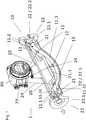
1 skizziert den Aufbau eines typischen Coriolis-Messgeräts;2 a) zeigt eine Aufsicht auf eine Spulenvorrichtung, und2b) und2c ) zeigen jeweils eine beispielhafte erfindungsgemäße Ausgestaltung einer Spulenvorrichtung und einer Magnetvorrichtung;3 a) bisd ) zeigen verschiedene beispielhafte erfindungsgemäße Ausgestaltungen eines Magnets;
1 outlines the structure of a typical Coriolis measuring device;2 a) shows a plan view of a coil device, and2 B) and2c ) each show an exemplary embodiment of a coil device and a magnet device according to the invention;3 a) tod ) show various exemplary embodiments of a magnet according to the invention;
Der Coriolis-Messaufnehmer ist mit einem Elektronikgehäuse
Der Coriolis-Messaufnehmer weist ferner eine Fixiervorrichtung
Ein erfindungsgemäßes Coriolis-Messgerät ist nicht auf das Vorhandensein zweier Messrohre beschränkt. So sind auch Einrohr- oder Mehrrohrsysteme mit mehr als zwei Rohren denkbar.A Coriolis measuring device according to the invention is not limited to the presence of two measuring tubes. One-pipe or multi-pipe systems with more than two pipes are also conceivable.
Die Spulenvorrichtungen bzw. Magnetvorrichtungen sind über dafür vorgesehene Befestigungsvorrichtungen entweder an einem entsprechenden Messrohr oder beispielsweise am Trägerkörper befestigt. Der Fachmann wird eine Befestigungsvorrichtung gemäß seiner Bedürfnisse bzw. gemäß technischer Anforderungen Einrichten.The coil devices or magnetic devices are fastened either to a corresponding measuring tube or, for example, to the carrier body via fastening devices provided for this purpose. The person skilled in the art will set up a fastening device in accordance with his needs or technical requirements.
Bevorzugt befindet sich einem Ruhezustand des mindestens einen Messrohrs eine Grenze zwischen den Magneten eines Paars projiziert auf eine Querschnittsebene der Spule zumindest abschnittsweise im Zentralbereich befindlich. Auf diese Weise wird eine Auswirkung einer Relativbewegung auf die Spule bzgl. der Induktion einer elektrischen Spannung verstärkt. Es ist weiterhin vorteilhaft, wenn eine räumliche Ausdehnung des ersten Paars Magnete entlang der Bewegungsrichtung der Relativbewegung größer ist als der Zentralbereich der Spule.There is preferably a state of rest of the at least one measuring tube, a boundary between the magnets of a pair projected onto a cross-sectional plane of the coil, at least in sections, in the central region. In this way, an effect of a relative movement on the coil with respect to the induction of an electrical voltage is amplified. It is furthermore advantageous if a spatial expansion of the first pair of magnets along the direction of movement of the relative movement is greater than the central region of the coil.
Die Halterung kann wie hier gezeigt, eine U-Form aufweisen mit einem ersten Ausleger
Die in
Die Halterung weist dabei eine konvexe Einhüllende auf, welche eine typische Abmessung von 8 Millimeter Länge, 9 Millimeter Breite, und 5 Millimeter Höhe, wobei tatsächliche Abmessungen jeweils um bis zu 30% von den genannten Abmessungen abweichen können, wobei tatsächliche Seitenverhältnisse entsprechend von den aus den genannten Abmessungen hervorgehenden Seitenverhältnissen abweichen können.The holder has a convex envelope, which has a typical dimension of 8 millimeters in length, 9 millimeters in width, and 5 millimeters in height, whereby actual dimensions can differ by up to 30% from the stated dimensions, with actual aspect ratios correspondingly from aspect ratios resulting from the dimensions mentioned.
Ein geeignetes Material für die Halterung kann beispielsweise ein nichtrostender ferritischer Edelstahl, insbesondere mit der Werkstoffnummer 1.4105 sein.A suitable material for the holder can be, for example, a rustproof ferritic stainless steel, in particular with the material number 1.4105.
Die Magnete sind beispielsweise aus einer Samarium-Kobalt-Legierung oder aus einer Aluminium-Nickel-Kobalt-Legierung gefertigt.The magnets are made, for example, from a samarium-cobalt alloy or from an aluminum-nickel-cobalt alloy.
Die Halterung weist jeweils eine zweite geometrische Struktur
Eine erste geometrische Struktur bzw. zweite geometrische Struktur kann auch andere als die gezeigten Formen aufweisen, wie beispielsweis eine dreiecksform.A first geometric structure or second geometric structure can also have shapes other than those shown, such as a triangular shape.
Auf diese Weise können die Magnete sauber positioniert werden. Jedoch ist die Fertigung der Magnete sowie der Halterungen technisch aufwändiger.In this way, the magnets can be positioned properly. However, the manufacture of the magnets and the brackets is technically more complex.
BezugszeichenlisteReference symbol list
- 11
- Coriolis-MessgerätCoriolis measuring device
- 1010th
- Coriolis-MessaufnehmerCoriolis sensors
- 1111
- MessrohrMeasuring tube
- 11.111.1
- Einlaufenema
- 11.211.2
- AuslaufSpout
- 11.3111.31
- erstes Messrohrfirst measuring tube
- 11.3211.32
- zweites Messrohrsecond measuring tube
- 1212
- ErregerPathogen
- 1313
- Sensorsensor
- 1414
- SpulenvorrichtungCoil device
- 14.1114.11
- erste Seite der Spulenvorrichtungfirst side of the coil device
- 14.1214.12
- zweite Seite der Spulenvorrichtungsecond side of the coil device
- 14.214.2
- SpuleKitchen sink
- 14.2114.21
- ZentralbereichCentral area
- 14.2214.22
- WindungsbereichWinding area
- 1515
- MagnetvorrichtungMagnetic device
- 15.115.1
- erstes Paar Magnetefirst pair of magnets
- 15.11November 15
- erster Magnet des ersten Paarsfirst magnet of the first pair
- 15.1215/12
- zweiter Magnet des ersten Paarssecond magnet of the first pair
- 15.215.2
- zweites Paar Magnetesecond pair of magnets
- 15.315.3
- magnetisch leitfähige Halterungmagnetically conductive holder
- 15.3115.31
- erster Auslegerfirst boom
- 15.3215.32
- zweiter Auslegersecond boom
- 15.3315.33
- verbindende Basisconnecting basis
- 15.31115,311
- Innenseite des ersten AuslegersInside of the first boom
- 1616
- KontaktflächeContact area
- 16.116.1
- erste geometrische Strukturfirst geometric structure
- 16.11November 16
- konkave Krümmungconcave curvature
- 16.1216.12
- konvexe Krümmungconvex curvature
- 16.1316.13
- Vorsprunghead Start
- 16.1416.14
- Vertiefungdeepening
- 16.216.2
- zweite geometrische Struktursecond geometric structure
- 2020th
- TrägerkörperCarrier body
- 2121st
- FixiervorrichtungFixing device
- 2222
- SammlerCollector
- 22.122.1
- erster Sammlerfirst collector
- 22.222.2
- zweiter Sammlersecond collector
- 2323
- ProzessanschlussProcess connection
- 23.123.1
- Flanschflange
- 2424th
- elektrische Verbindungenelectrical connections
- 2525th
- KabelführungenCable guides
ZITATE ENTHALTEN IN DER BESCHREIBUNG QUOTES INCLUDE IN THE DESCRIPTION
Diese Liste der vom Anmelder aufgeführten Dokumente wurde automatisiert erzeugt und ist ausschließlich zur besseren Information des Lesers aufgenommen. Die Liste ist nicht Bestandteil der deutschen Patent- bzw. Gebrauchsmusteranmeldung. Das DPMA übernimmt keinerlei Haftung für etwaige Fehler oder Auslassungen.This list of documents listed by the applicant has been generated automatically and is only included for the better information of the reader. The list is not part of the German patent or utility model application. The DPMA assumes no liability for any errors or omissions.
Zitierte PatentliteraturPatent literature cited
- DE 102018119941 [0003]DE 102018119941 [0003]
Claims (15)
Translated fromGermanPriority Applications (5)
| Application Number | Priority Date | Filing Date | Title |
|---|---|---|---|
| DE102018131742.5ADE102018131742B4 (en) | 2018-12-11 | 2018-12-11 | Coriolis sensor of a Coriolis meter and a Coriolis meter |
| CN201980080663.XACN113167623B (en) | 2018-12-11 | 2019-11-21 | Measuring sensor of coriolis measuring instrument and coriolis measuring instrument |
| EP19808760.3AEP3894803B1 (en) | 2018-12-11 | 2019-11-21 | Coriolis measuring sensor of a coriolis measuring instrument and a coriolis measuring instrument |
| PCT/EP2019/082018WO2020120092A1 (en) | 2018-12-11 | 2019-11-21 | Coriolis measuring sensor of a coriolis measuring instrument and a coriolis measuring instrument |
| US17/413,449US11796364B2 (en) | 2018-12-11 | 2019-11-21 | Coriolis measuring sensor of a Coriolis measuring instrument and a Coriolis measuring instrument |
Applications Claiming Priority (1)
| Application Number | Priority Date | Filing Date | Title |
|---|---|---|---|
| DE102018131742.5ADE102018131742B4 (en) | 2018-12-11 | 2018-12-11 | Coriolis sensor of a Coriolis meter and a Coriolis meter |
Publications (2)
| Publication Number | Publication Date |
|---|---|
| DE102018131742A1true DE102018131742A1 (en) | 2020-06-18 |
| DE102018131742B4 DE102018131742B4 (en) | 2022-12-01 |
Family
ID=68654481
Family Applications (1)
| Application Number | Title | Priority Date | Filing Date |
|---|---|---|---|
| DE102018131742.5AExpired - Fee RelatedDE102018131742B4 (en) | 2018-12-11 | 2018-12-11 | Coriolis sensor of a Coriolis meter and a Coriolis meter |
Country Status (5)
| Country | Link |
|---|---|
| US (1) | US11796364B2 (en) |
| EP (1) | EP3894803B1 (en) |
| CN (1) | CN113167623B (en) |
| DE (1) | DE102018131742B4 (en) |
| WO (1) | WO2020120092A1 (en) |
Cited By (1)
| Publication number | Priority date | Publication date | Assignee | Title |
|---|---|---|---|---|
| US20210310920A1 (en)* | 2018-08-08 | 2021-10-07 | Endress+Hauser Flowtec Ag | Measuring transducer and measurement device |
Citations (5)
| Publication number | Priority date | Publication date | Assignee | Title |
|---|---|---|---|---|
| US4756198A (en)* | 1986-01-24 | 1988-07-12 | Exac Corporation | Sensor apparatus for mass flow rate measurement system |
| JPH1151733A (en)* | 1997-08-04 | 1999-02-26 | Tokico Ltd | Vibration measuring device |
| DE69327772T2 (en)* | 1992-11-19 | 2000-06-29 | Oval Corp., Tokio/Tokyo | Coriolis flow meter |
| DE102015120087A1 (en)* | 2015-11-19 | 2017-05-24 | Endress + Hauser Flowtec Ag | Field device of process measuring technology with a vibration-type sensor |
| DE102018119941A1 (en) | 2018-08-16 | 2020-02-20 | Endress+Hauser Flowtec Ag | Sensor and measuring device |
Family Cites Families (10)
| Publication number | Priority date | Publication date | Assignee | Title |
|---|---|---|---|---|
| US4811606A (en)* | 1987-04-20 | 1989-03-14 | Tokico, Ltd. | Mass flowmeter |
| DE3814702A1 (en) | 1987-11-12 | 1989-05-24 | Bosch Gmbh Robert | DEVICE FOR ACTUATING THE THROTTLE VALVE OF AN INTERNAL COMBUSTION ENGINE, IN PARTICULAR A MOTOR VEHICLE |
| JPH08254452A (en)* | 1995-03-16 | 1996-10-01 | Tokico Ltd | Vibration measuring device |
| JP2005106574A (en)* | 2003-09-30 | 2005-04-21 | Hitachi Ltd | Vibration measuring device |
| JP4711056B2 (en)* | 2005-06-01 | 2011-06-29 | 株式会社タツノ・メカトロニクス | Coriolis mass flow meter |
| DE102011013263B4 (en)* | 2011-03-07 | 2018-02-15 | Krohne Ag | Coriolis mass flowmeter |
| DE102012201592B3 (en)* | 2012-02-03 | 2013-03-14 | Siemens Aktiengesellschaft | Coriolis mass flow measuring device for measuring mass flow of fluid, has vibration absorbers with linear variable hybrid coil having cores whose ends are coupled with measuring tubes such that coefficient Of coupling of coils varies |
| US10107784B2 (en)* | 2014-12-29 | 2018-10-23 | Concentric Meter Corporation | Electromagnetic transducer |
| DE102015109790B4 (en)* | 2015-06-18 | 2025-08-14 | Endress + Hauser Flowtec Ag | Coriolis mass flow meter and/or density meter |
| DE202017006709U1 (en)* | 2017-12-07 | 2018-02-12 | Heinrichs Messtechnik Gmbh | Coriolis mass flowmeter |
- 2018
- 2018-12-11DEDE102018131742.5Apatent/DE102018131742B4/ennot_activeExpired - Fee Related
- 2019
- 2019-11-21EPEP19808760.3Apatent/EP3894803B1/enactiveActive
- 2019-11-21USUS17/413,449patent/US11796364B2/enactiveActive
- 2019-11-21CNCN201980080663.XApatent/CN113167623B/enactiveActive
- 2019-11-21WOPCT/EP2019/082018patent/WO2020120092A1/ennot_activeCeased
Patent Citations (5)
| Publication number | Priority date | Publication date | Assignee | Title |
|---|---|---|---|---|
| US4756198A (en)* | 1986-01-24 | 1988-07-12 | Exac Corporation | Sensor apparatus for mass flow rate measurement system |
| DE69327772T2 (en)* | 1992-11-19 | 2000-06-29 | Oval Corp., Tokio/Tokyo | Coriolis flow meter |
| JPH1151733A (en)* | 1997-08-04 | 1999-02-26 | Tokico Ltd | Vibration measuring device |
| DE102015120087A1 (en)* | 2015-11-19 | 2017-05-24 | Endress + Hauser Flowtec Ag | Field device of process measuring technology with a vibration-type sensor |
| DE102018119941A1 (en) | 2018-08-16 | 2020-02-20 | Endress+Hauser Flowtec Ag | Sensor and measuring device |
Non-Patent Citations (1)
| Title |
|---|
| WIKIPEDIA - Force between magnets: Bearbeitungsstand vom 28.11.2018, URL: https://en.wikipedia.org/w/index.php?title=Force_between_magnets&oldid=871010237* |
Cited By (2)
| Publication number | Priority date | Publication date | Assignee | Title |
|---|---|---|---|---|
| US20210310920A1 (en)* | 2018-08-08 | 2021-10-07 | Endress+Hauser Flowtec Ag | Measuring transducer and measurement device |
| US11933806B2 (en)* | 2018-08-08 | 2024-03-19 | Endress+Hauser Flowtec Ag | Measuring transducer and measurement device |
Also Published As
| Publication number | Publication date |
|---|---|
| CN113167623B (en) | 2024-01-30 |
| US11796364B2 (en) | 2023-10-24 |
| US20220074776A1 (en) | 2022-03-10 |
| EP3894803A1 (en) | 2021-10-20 |
| EP3894803B1 (en) | 2023-08-16 |
| CN113167623A (en) | 2021-07-23 |
| DE102018131742B4 (en) | 2022-12-01 |
| WO2020120092A1 (en) | 2020-06-18 |
Similar Documents
| Publication | Publication Date | Title |
|---|---|---|
| EP3837504B1 (en) | Transmitter of a measuring device and measuring device | |
| DE102017131202A1 (en) | Magnetic-inductive flowmeter | |
| EP3172537B1 (en) | Magnetic inductive flowmeter | |
| DE102011083549A1 (en) | Magnetic-inductive flowmeter | |
| DE102015116679A1 (en) | Magnetic-inductive flowmeter | |
| DE102018119941A1 (en) | Sensor and measuring device | |
| DE102018102379A1 (en) | Coriolis sensor and Coriolis meter | |
| EP3894803B1 (en) | Coriolis measuring sensor of a coriolis measuring instrument and a coriolis measuring instrument | |
| EP2113069A1 (en) | Device for measuring the volumetric or mass flow of a medium in a pipeline | |
| DE102018105089A1 (en) | Coriolismessgerät | |
| EP3948178B1 (en) | Coriolis sensor and coriolis measuring device | |
| EP3935350B1 (en) | Coriolis sensor and coriolis measuring device with coriolis sensor | |
| WO2016041725A1 (en) | Magnetoinductive flowmeter having a magnetic system with at least four coils | |
| EP3833940B1 (en) | Measuring sensor and measurement device | |
| EP0737303B1 (en) | Magnetic-inductive measurement apparatus for flowing media | |
| WO2021063711A1 (en) | Magnetically inductive flow meter | |
| WO2020030502A1 (en) | Coil apparatus of a vibration sensor or of a vibration generator and measuring sensor or measuring instrument | |
| WO2005093376A2 (en) | Medium flow rate measuring and/ or controlling device | |
| DE102024123800B3 (en) | Magnetic-inductive flowmeter | |
| DE102019122210B3 (en) | Measuring tube of a Coriolis measuring sensor with an LTCC ceramic, Coriolis measuring sensor with such a measuring tube and Coriolis measuring device with such a Coriolis measuring sensor. | |
| DE102015202985B4 (en) | Use of an electromagnetic sensor and method for measuring magnetic material properties | |
| DE102015116673A1 (en) | Magnetic-inductive flowmeter | |
| DE3435910A1 (en) | Magnetic-inductive flow meter having replaceable flow sensors | |
| DE202013007140U1 (en) | Magnetic-inductive flowmeter | |
| DE102017115156A1 (en) | Method for producing a magnetic-inductive flowmeter and a magnetic-inductive flowmeter |
Legal Events
| Date | Code | Title | Description |
|---|---|---|---|
| R012 | Request for examination validly filed | ||
| R016 | Response to examination communication | ||
| R016 | Response to examination communication | ||
| R018 | Grant decision by examination section/examining division | ||
| R020 | Patent grant now final | ||
| R119 | Application deemed withdrawn, or ip right lapsed, due to non-payment of renewal fee |