DE102018131665A1 - Sleeve for developing a screw into a spacer screw, screw with such a sleeve and turning tool for screwing in the screw - Google Patents
Sleeve for developing a screw into a spacer screw, screw with such a sleeve and turning tool for screwing in the screwDownload PDFInfo
- Publication number
- DE102018131665A1 DE102018131665A1DE102018131665.8ADE102018131665ADE102018131665A1DE 102018131665 A1DE102018131665 A1DE 102018131665A1DE 102018131665 ADE102018131665 ADE 102018131665ADE 102018131665 A1DE102018131665 A1DE 102018131665A1
- Authority
- DE
- Germany
- Prior art keywords
- screw
- sleeve
- tool
- turning tool
- screwdriver bit
- Prior art date
- Legal status (The legal status is an assumption and is not a legal conclusion. Google has not performed a legal analysis and makes no representation as to the accuracy of the status listed.)
- Pending
Links
Images


Classifications
- F—MECHANICAL ENGINEERING; LIGHTING; HEATING; WEAPONS; BLASTING
- F16—ENGINEERING ELEMENTS AND UNITS; GENERAL MEASURES FOR PRODUCING AND MAINTAINING EFFECTIVE FUNCTIONING OF MACHINES OR INSTALLATIONS; THERMAL INSULATION IN GENERAL
- F16B—DEVICES FOR FASTENING OR SECURING CONSTRUCTIONAL ELEMENTS OR MACHINE PARTS TOGETHER, e.g. NAILS, BOLTS, CIRCLIPS, CLAMPS, CLIPS OR WEDGES; JOINTS OR JOINTING
- F16B25/00—Screws that cut thread in the body into which they are screwed, e.g. wood screws
- F16B25/001—Screws that cut thread in the body into which they are screwed, e.g. wood screws characterised by the material of the body into which the screw is screwed
- F16B25/0015—Screws that cut thread in the body into which they are screwed, e.g. wood screws characterised by the material of the body into which the screw is screwed the material being a soft organic material, e.g. wood or plastic
- B—PERFORMING OPERATIONS; TRANSPORTING
- B25—HAND TOOLS; PORTABLE POWER-DRIVEN TOOLS; MANIPULATORS
- B25B—TOOLS OR BENCH DEVICES NOT OTHERWISE PROVIDED FOR, FOR FASTENING, CONNECTING, DISENGAGING OR HOLDING
- B25B15/00—Screwdrivers
- B25B15/001—Screwdrivers characterised by material or shape of the tool bit
- B25B15/004—Screwdrivers characterised by material or shape of the tool bit characterised by cross-section
- B25B15/005—Screwdrivers characterised by material or shape of the tool bit characterised by cross-section with cross- or star-shaped cross-section
- B—PERFORMING OPERATIONS; TRANSPORTING
- B25—HAND TOOLS; PORTABLE POWER-DRIVEN TOOLS; MANIPULATORS
- B25B—TOOLS OR BENCH DEVICES NOT OTHERWISE PROVIDED FOR, FOR FASTENING, CONNECTING, DISENGAGING OR HOLDING
- B25B23/00—Details of, or accessories for, spanners, wrenches, screwdrivers
- B25B23/0007—Connections or joints between tool parts
- B25B23/0035—Connection means between socket or screwdriver bit and tool
- F—MECHANICAL ENGINEERING; LIGHTING; HEATING; WEAPONS; BLASTING
- F16—ENGINEERING ELEMENTS AND UNITS; GENERAL MEASURES FOR PRODUCING AND MAINTAINING EFFECTIVE FUNCTIONING OF MACHINES OR INSTALLATIONS; THERMAL INSULATION IN GENERAL
- F16B—DEVICES FOR FASTENING OR SECURING CONSTRUCTIONAL ELEMENTS OR MACHINE PARTS TOGETHER, e.g. NAILS, BOLTS, CIRCLIPS, CLAMPS, CLIPS OR WEDGES; JOINTS OR JOINTING
- F16B23/00—Specially shaped nuts or heads of bolts or screws for rotations by a tool
- F16B23/0092—Specially shaped nuts or heads of bolts or screws for rotations by a tool with a head engageable by two or more different tools
- F—MECHANICAL ENGINEERING; LIGHTING; HEATING; WEAPONS; BLASTING
- F16—ENGINEERING ELEMENTS AND UNITS; GENERAL MEASURES FOR PRODUCING AND MAINTAINING EFFECTIVE FUNCTIONING OF MACHINES OR INSTALLATIONS; THERMAL INSULATION IN GENERAL
- F16B—DEVICES FOR FASTENING OR SECURING CONSTRUCTIONAL ELEMENTS OR MACHINE PARTS TOGETHER, e.g. NAILS, BOLTS, CIRCLIPS, CLAMPS, CLIPS OR WEDGES; JOINTS OR JOINTING
- F16B25/00—Screws that cut thread in the body into which they are screwed, e.g. wood screws
- F16B25/0036—Screws that cut thread in the body into which they are screwed, e.g. wood screws characterised by geometric details of the screw
- F16B25/0042—Screws that cut thread in the body into which they are screwed, e.g. wood screws characterised by geometric details of the screw characterised by the geometry of the thread, the thread being a ridge wrapped around the shaft of the screw
- F16B25/0057—Screws that cut thread in the body into which they are screwed, e.g. wood screws characterised by geometric details of the screw characterised by the geometry of the thread, the thread being a ridge wrapped around the shaft of the screw the screw having distinct axial zones, e.g. multiple axial thread sections with different pitch or thread cross-sections
- F16B25/0063—Screws that cut thread in the body into which they are screwed, e.g. wood screws characterised by geometric details of the screw characterised by the geometry of the thread, the thread being a ridge wrapped around the shaft of the screw the screw having distinct axial zones, e.g. multiple axial thread sections with different pitch or thread cross-sections with a non-threaded portion on the shaft of the screw
- F—MECHANICAL ENGINEERING; LIGHTING; HEATING; WEAPONS; BLASTING
- F16—ENGINEERING ELEMENTS AND UNITS; GENERAL MEASURES FOR PRODUCING AND MAINTAINING EFFECTIVE FUNCTIONING OF MACHINES OR INSTALLATIONS; THERMAL INSULATION IN GENERAL
- F16B—DEVICES FOR FASTENING OR SECURING CONSTRUCTIONAL ELEMENTS OR MACHINE PARTS TOGETHER, e.g. NAILS, BOLTS, CIRCLIPS, CLAMPS, CLIPS OR WEDGES; JOINTS OR JOINTING
- F16B25/00—Screws that cut thread in the body into which they are screwed, e.g. wood screws
- F16B25/0036—Screws that cut thread in the body into which they are screwed, e.g. wood screws characterised by geometric details of the screw
- F16B25/0094—Screws that cut thread in the body into which they are screwed, e.g. wood screws characterised by geometric details of the screw the screw being assembled or manufactured from several components, e.g. a tip out of a first material welded to shaft of a second material
- F—MECHANICAL ENGINEERING; LIGHTING; HEATING; WEAPONS; BLASTING
- F16—ENGINEERING ELEMENTS AND UNITS; GENERAL MEASURES FOR PRODUCING AND MAINTAINING EFFECTIVE FUNCTIONING OF MACHINES OR INSTALLATIONS; THERMAL INSULATION IN GENERAL
- F16B—DEVICES FOR FASTENING OR SECURING CONSTRUCTIONAL ELEMENTS OR MACHINE PARTS TOGETHER, e.g. NAILS, BOLTS, CIRCLIPS, CLAMPS, CLIPS OR WEDGES; JOINTS OR JOINTING
- F16B25/00—Screws that cut thread in the body into which they are screwed, e.g. wood screws
- F16B25/10—Screws performing an additional function to thread-forming, e.g. drill screws or self-piercing screws
- F—MECHANICAL ENGINEERING; LIGHTING; HEATING; WEAPONS; BLASTING
- F16—ENGINEERING ELEMENTS AND UNITS; GENERAL MEASURES FOR PRODUCING AND MAINTAINING EFFECTIVE FUNCTIONING OF MACHINES OR INSTALLATIONS; THERMAL INSULATION IN GENERAL
- F16B—DEVICES FOR FASTENING OR SECURING CONSTRUCTIONAL ELEMENTS OR MACHINE PARTS TOGETHER, e.g. NAILS, BOLTS, CIRCLIPS, CLAMPS, CLIPS OR WEDGES; JOINTS OR JOINTING
- F16B35/00—Screw-bolts; Stay-bolts; Screw-threaded studs; Screws; Set screws
- F16B35/04—Screw-bolts; Stay-bolts; Screw-threaded studs; Screws; Set screws with specially-shaped head or shaft in order to fix the bolt on or in an object
- F16B35/06—Specially-shaped heads
- F16B35/065—Specially-shaped heads with self-countersink-cutting means
- F—MECHANICAL ENGINEERING; LIGHTING; HEATING; WEAPONS; BLASTING
- F16—ENGINEERING ELEMENTS AND UNITS; GENERAL MEASURES FOR PRODUCING AND MAINTAINING EFFECTIVE FUNCTIONING OF MACHINES OR INSTALLATIONS; THERMAL INSULATION IN GENERAL
- F16B—DEVICES FOR FASTENING OR SECURING CONSTRUCTIONAL ELEMENTS OR MACHINE PARTS TOGETHER, e.g. NAILS, BOLTS, CIRCLIPS, CLAMPS, CLIPS OR WEDGES; JOINTS OR JOINTING
- F16B5/00—Joining sheets or plates, e.g. panels, to one another or to strips or bars parallel to them
- F16B5/02—Joining sheets or plates, e.g. panels, to one another or to strips or bars parallel to them by means of fastening members using screw-thread
- F16B5/0216—Joining sheets or plates, e.g. panels, to one another or to strips or bars parallel to them by means of fastening members using screw-thread the position of the plates to be connected being adjustable
- F16B5/0233—Joining sheets or plates, e.g. panels, to one another or to strips or bars parallel to them by means of fastening members using screw-thread the position of the plates to be connected being adjustable allowing for adjustment perpendicular to the plane of the plates
- F—MECHANICAL ENGINEERING; LIGHTING; HEATING; WEAPONS; BLASTING
- F16—ENGINEERING ELEMENTS AND UNITS; GENERAL MEASURES FOR PRODUCING AND MAINTAINING EFFECTIVE FUNCTIONING OF MACHINES OR INSTALLATIONS; THERMAL INSULATION IN GENERAL
- F16B—DEVICES FOR FASTENING OR SECURING CONSTRUCTIONAL ELEMENTS OR MACHINE PARTS TOGETHER, e.g. NAILS, BOLTS, CIRCLIPS, CLAMPS, CLIPS OR WEDGES; JOINTS OR JOINTING
- F16B5/00—Joining sheets or plates, e.g. panels, to one another or to strips or bars parallel to them
- F16B5/02—Joining sheets or plates, e.g. panels, to one another or to strips or bars parallel to them by means of fastening members using screw-thread
- F16B5/0283—Joining sheets or plates, e.g. panels, to one another or to strips or bars parallel to them by means of fastening members using screw-thread with an externally threaded sleeve around the neck or the head of the screw-threaded element for adjustably fastening a plate or frame or the like to a fixed element
- E—FIXED CONSTRUCTIONS
- E04—BUILDING
- E04F—FINISHING WORK ON BUILDINGS, e.g. STAIRS, FLOORS
- E04F13/00—Coverings or linings, e.g. for walls or ceilings
- E04F13/07—Coverings or linings, e.g. for walls or ceilings composed of covering or lining elements; Sub-structures therefor; Fastening means therefor
- E04F13/08—Coverings or linings, e.g. for walls or ceilings composed of covering or lining elements; Sub-structures therefor; Fastening means therefor composed of a plurality of similar covering or lining elements
- E04F13/0801—Separate fastening elements
- E04F13/0803—Separate fastening elements with load-supporting elongated furring elements between wall and covering elements
- E04F13/0805—Separate fastening elements with load-supporting elongated furring elements between wall and covering elements with additional fastening elements between furring elements and the wall
- E04F13/0807—Separate fastening elements with load-supporting elongated furring elements between wall and covering elements with additional fastening elements between furring elements and the wall adjustable perpendicular to the wall
- E—FIXED CONSTRUCTIONS
- E04—BUILDING
- E04F—FINISHING WORK ON BUILDINGS, e.g. STAIRS, FLOORS
- E04F13/00—Coverings or linings, e.g. for walls or ceilings
- E04F13/07—Coverings or linings, e.g. for walls or ceilings composed of covering or lining elements; Sub-structures therefor; Fastening means therefor
- E04F13/08—Coverings or linings, e.g. for walls or ceilings composed of covering or lining elements; Sub-structures therefor; Fastening means therefor composed of a plurality of similar covering or lining elements
- E04F13/0801—Separate fastening elements
- E04F13/0832—Separate fastening elements without load-supporting elongated furring elements between wall and covering elements
- E04F13/0853—Separate fastening elements without load-supporting elongated furring elements between wall and covering elements adjustable perpendicular to the wall
Landscapes
- Engineering & Computer Science (AREA)
- General Engineering & Computer Science (AREA)
- Mechanical Engineering (AREA)
- Physics & Mathematics (AREA)
- Geometry (AREA)
- Life Sciences & Earth Sciences (AREA)
- Chemical & Material Sciences (AREA)
- Dispersion Chemistry (AREA)
- Wood Science & Technology (AREA)
- Dowels (AREA)
- Details Of Spanners, Wrenches, And Screw Drivers And Accessories (AREA)
Abstract
Translated fromGerman
Description
Translated fromGermanDie Erfindung betrifft eine Hülse zur Weiterbildung einer einen Schraubenkopf aufweisenden Schraube in eine Distanzschraube mit den Merkmalen des Oberbegriffs des Anspruchs 1, eine Schraube mit einer solchen Hülse mit den Merkmalen des Oberbegriffs des Anspruchs 4 und ein Drehwerkzeug zum Einschrauben der Schraube in einen Ankergrund und zu einer Abstandseinstellung mit den Merkmalen des Oberbegriffs des Anspruchs 6.The invention relates to a sleeve for developing a screw head screw into a spacer screw with the features of the preamble of claim 1, a screw with such a sleeve with the features of the preamble of claim 4 and a turning tool for screwing the screw into an anchor base and a distance setting with the features of the preamble of claim 6.
Distanzschrauben sind bekannt. Sie werden durch ein Bauteil wie beispielsweise eine Wand- oder Deckenverkleidung in einen Ankergrund wie beispielsweise eine Wand oder eine Decke geschraubt und weisen in einem Bereich, der sich am Ende des Einschraubens in dem Bauteil befindet, umlaufende Rippen auf, die dem Bauteil einen axialen Halt auf der Distanzschraube geben. Im Ankergrund wird die Distanzschraube beispielsweise in einen Spreizdübel in einem Bohrloch in dem Ankergrund geschraubt. Durch Rückdrehen der Distanzschraube wird ein gewünschter Abstand zwischen dem Bauteil und dem Ankergrund hergestellt.Spacer screws are known. They are screwed through a component such as a wall or ceiling cladding into an anchor base such as a wall or a ceiling and have circumferential ribs in an area that is at the end of the screwing in the component, which provide the component with an axial hold on the spacer screw. In the anchor base, the spacer screw is screwed, for example, into an expansion plug in a borehole in the anchor base. The desired distance between the component and the anchor base is created by turning back the spacer screw.
Die europäische Patentanmeldung
Aufgabe der Erfindung ist, eine vereinfachte Hülse für eine Abstandsmontage eines Bauteils an einem Ankergrund, eine Schraube mit der Hülse und ein Drehwerkzeug für die Abstandsmontage mit der Hülse vorzuschlagen.The object of the invention is to propose a simplified sleeve for spaced mounting of a component on an anchor base, a screw with the sleeve and a turning tool for spaced mounting with the sleeve.
Diese Aufgabe wird erfindungsgemäß durch die Merkmale der Ansprüche 1, 4 und 6 gelöst.This object is achieved by the features of claims 1, 4 and 6.
Die erfindungsgemäße Hülse mit den Merkmalen des Anspruchs 1 ist als radial federnder Clip ausgebildet, der in radialer Richtung, das heißt seitlich beziehungsweise von einer Seite auf einen Schraubenschaft einer Schraube aufklipsbar ist. Die erfindungsgemäße Hülse ist also zumindest auf einem Teil ihrer axialen Länge kein geschlossenes Rohr, sondern weist eine Unterbrechung in einer Umfangswand auf, die sich vorzugsweise ausgehend von einem Stirnende der Hülse über zumindest einen Teil der axialen Länge der Hülse erstreckt. Die Unterbrechung kann achsparallel oder schräg zu einer achsparallelen Richtung beispielsweise wendelförmig, wellenförmig oder zick-zack-förmig verlaufen. Radial in einer Richtung zur Hülse gesehen erstreckt sich die Unterbrechung über weniger als 180° und die Hülse folglich über mehr als 180° in einer Umfangsrichtung, so dass eine lichte Breite der Unterbrechung radial in der einen Richtung zur Hülse gesehen kleiner als ein Innendurchmesser der Hülse ist. Bei einer beispielsweise wendelförmigen, wellenförmigen oder zick-zack-förmigen Unterbrechung kann die Unterbrechung auch breiter als 180° in der Umfangsrichtung sein, sofern ihre lichte Breite radial in der einen Richtung gesehen schmaler als 180° in der Umfangsrichtung ist. Jedenfalls ist die Hülse und ihre Unterbrechung so ausgebildet, dass die Hülse als radial federnder Clip in radialer Richtung beziehungsweise seitlich oder von einer Seite auf einen Schraubenschaft aufklipsbar ist und nach dem Aufklipsen so weit zusammen federt, dass sie durch Formschluss radial auf einem Schraubenschaft hält, dessen Durchmesser so groß wie der Innendurchmesser der Hülse ist. Selbstverständlich hält die Hülse in radialer Richtung auch auf einem Schraubenschaft mit einem größeren Durchmesser, und auf einem Schraubenschaft mit einem Durchmesser, der zwar kleiner als der Innendurchmesser der Hülse, jedoch größer als die lichte Breite der Unterbrechung - radial in der einen Richtung der Hülse gesehen - ist.The sleeve according to the invention with the features of claim 1 is designed as a radially resilient clip which can be clipped onto a screw shaft of a screw in the radial direction, that is to say laterally or from one side. The sleeve according to the invention is therefore not a closed tube over at least part of its axial length, but instead has an interruption in a circumferential wall, which preferably extends from at least one end of the sleeve over at least part of the axial length of the sleeve. The interruption can run axially parallel or obliquely to an axially parallel direction, for example in a helical, undulating or zigzag shape. Seen radially in a direction to the sleeve, the interruption extends over less than 180 ° and the sleeve consequently over more than 180 ° in a circumferential direction, so that a clear width of the interruption, seen radially in one direction to the sleeve, is smaller than an inner diameter of the sleeve is. In the case of, for example, a helical, undulating or zigzag-shaped interruption, the interruption can also be wider than 180 ° in the circumferential direction, provided that the clear width seen radially in one direction is narrower than 180 ° in the circumferential direction. In any case, the sleeve and its interruption are designed such that the sleeve can be clipped onto a screw shaft as a radially resilient clip in the radial direction or laterally or from one side and, after clipping on, springs together to such an extent that it holds radially on a screw shaft by positive locking, whose diameter is as large as the inside diameter of the sleeve. Of course, the sleeve also holds in the radial direction on a screw shaft with a larger diameter, and on a screw shaft with a diameter that is smaller than the inside diameter of the sleeve, but larger than the clear width of the interruption - seen radially in one direction of the sleeve - is.
Die erfindungsgemäße Hülse ist drehbar auf einer Schraube, auf die beziehungsweise auf deren Schraubenschaft die Hülse aufgeklipst ist.The sleeve according to the invention is rotatable on a screw onto or onto the screw shaft of which the sleeve is clipped.
Die erfindungsgemäße Hülse weist ein Außengewinde, insbesondere ein Holzschraubengewinde zu einem Einschrauben der Hülse in ein Durchgangsloch in einem Bauteil auf.The sleeve according to the invention has an external thread, in particular a wood screw thread, for screwing the sleeve into a through hole in a component.
Des Weiteren weist die erfindungsgemäße Hülse ein unteres Widerlager und ein oberes Widerlager auf, wobei das obere Widerlager durch Anlage an einer Oberseite eines Schraubenkopfs die Hülse axial in einer Richtung und das untere Widerlager durch Anlage an einer Unterseite des Schraubenkopfs die Hülse axial in einer entgegengesetzten Richtung an der Schraube festlegt, auf deren Schraubenschaft die Hülse im Bereich des Schraubenkopfs aufgeklipst ist. Als „Oberseite“ wird eine einem Schraubengewinde und dem Schraubenschaft der Schraube abgewandte, und als „Unterseite“ eine dem Schraubengewinde und dem Schraubenschaft der Schraube zugewandte Seite des Schraubenkopfs bezeichnet. Als „oberes Widerlager“ der erfindungsgemäßen Hülse wird das der Oberseite des Schraubenkopfs zugeordnete Widerlager und als „unteres Widerlager“ der erfindungsgemäßen Hülse das der Unterseite des Schraubenkopfs zugeordnete Widerlager bezeichnet. Die beiden Widerlager halten die Hülse vorzugsweise axial spielfrei oder mit wenig Axialspiel von vorzugsweise weniger als einer Steigung des Gewindes, wobei ein größeres Axialspiel nicht grundsätzlich ausgeschlossen ist, wenngleich ein Axialspiel der Hülse auf der Schraube für die Abstandseinstellung unpraktisch erscheint und deswegen eine axial spielfreie oder auf der Schraube möglichst wenig Axialspiel aufweisende Hülse bevorzugt ist. Furthermore, the sleeve according to the invention has a lower abutment and an upper abutment, the upper abutment axially in one direction by abutment on an upper side of a screw head and the lower abutment axially in an opposite direction by abutment on an underside of the screw head to the screw, on the screw shaft of which the sleeve is clipped in the area of the screw head. The “top” is a side of the screw head facing away from a screw thread and the screw shaft of the screw, and the “bottom” is a side of the screw head facing the screw thread and the screw shaft of the screw. The “upper abutment” of the sleeve according to the invention is the abutment assigned to the top of the screw head and the “lower abutment” of the sleeve according to the invention is the abutment assigned to the underside of the screw head. The two abutments preferably keep the sleeve axially free of play or with little axial play of preferably less than a pitch of the thread, a larger axial play not being excluded in principle, although an axial play of the sleeve on the screw for adjusting the distance seems impractical and therefore an axial play free or sleeve with as little axial play as possible is preferred.
Die erfindungsgemäße Hülse weist einen Hülsenwerkzeugsitz, beispielsweise einen Innensechskant oder einen Innenstern, zu einem durch Formschluss drehfesten Ansetzen eines Drehwerkzeugs, beispielsweise eines Schraubendrehers, auf. Der Hülsenwerkzeugsitz befindet sich vorzugsweise koaxial auf oder über der Oberseite des Schraubenkopfs einer Schraube, wenn die Hülse in vorgesehener Weise auf den Schraubenschaft aufgeklipst ist.The sleeve according to the invention has a sleeve tool seat, for example an internal hexagon or an inner star, for attaching a turning tool, for example a screwdriver, which is non-rotatably due to positive locking. The sleeve tool seat is preferably located coaxially on or above the top of the screw head of a screw when the sleeve is clipped onto the screw shaft in the intended manner.
Außerdem weist die erfindungsgemäße Hülse eine Öffnung an einem dem oberen Widerlager zugeordneten Stirnende der Hülse auf, durch die ein Schraubenwerkzeugsitz am beziehungsweise im Schraubenkopf der Schraube zugänglich ist, auf deren Schraubenschaft die Hülse in vorgesehener Weise aufgeklipst ist. Der Schraubenwerkzeugsitz ist beispielsweise ebenfalls ein Innensechskant oder ein Innenstern oder beispielsweise auch ein Kreuzschlitz zu einem durch Formschluss drehfesten Ansetzen eines Drehwerkzeugs am Schraubenkopf der Schraube. Dadurch lässt sich eine Schraube, auf deren Schraubenschaft die erfindungsgemäße Hülse in vorgesehener Weise aufgeklipst ist, durch ein Bauteil in einen Ankergrund und zugleich die Hülse in das Bauteil einschrauben. Durch anschließendes Ausdrehen der Schraube um ein begrenztes Stück aus dem Ankergrund, ohne die aufgeklipste und in das Bauteil eingeschraubte Hülse mitzudrehen, lässt sich das Bauteil in einen gewünschten Abstand vom Ankergrund bringen.In addition, the sleeve according to the invention has an opening at an end face of the sleeve assigned to the upper abutment, through which a screw tool seat on or in the screw head of the screw is accessible, on the screw shaft of which the sleeve is clipped in the intended manner. The screw tool seat is, for example, also an internal hexagon or an inner star or, for example, also a cross recess for a turning tool to be attached to the screw head of the screw so that it is non-rotatable due to positive locking. As a result, a screw, on the screw shaft of which the sleeve according to the invention is clipped in the intended manner, can be screwed through a component into an anchor base and at the same time the sleeve into the component. By subsequently unscrewing the screw a limited distance from the anchor base without turning the clipped and screwed sleeve into the component, the component can be brought into the desired distance from the anchor base.
Vorzugsweise ist das obere Widerlager der erfindungsgemäßen Hülse ringförmig und befindet sich auf der Oberseite des Schraubenkopfs, wenn die Hülse in vorgesehener Weise auf den Schraubenschaft aufgeklipst ist. Das ringförmig ausgebildete obere Widerlager weist einen Innensechskant, einen Innenstern oder einen anders geformten Hülsenwerkzeugsitz zu dem durch Formschluss drehfesten Ansetzen des Drehwerkzeugs auf, der zugleich die Öffnung bildet, durch die der Schraubenwerkzeugsitz am oder im Schraubenkopf der Schraube zu dem durch Formschluss drehfesten Ansetzen des gleichen oder eines anderen Drehwerkzeugs zugänglich ist. Vorzugsweise ist der Hülsenwerkzeugsitz koaxial zu der Schraube, wenn die Hülse in vorgesehener Weise auf den Schraubenschaft aufgeklipst ist.The upper abutment of the sleeve according to the invention is preferably ring-shaped and is located on the top of the screw head when the sleeve is clipped onto the screw shaft in the intended manner. The ring-shaped upper abutment has a hexagon socket, an inner star or another shaped sleeve tool seat for the non-rotatable attachment of the turning tool, which at the same time forms the opening through which the screw tool seat on or in the screw head of the screw to the non-rotatable attachment of the same or another turning tool is accessible. The sleeve tool seat is preferably coaxial with the screw when the sleeve is clipped onto the screw shaft in the intended manner.
Eine Ausgestaltung der Erfindung sieht Frässchneiden an einem Außenumfang und/oder an einer Unterseite des unteren Widerlagers und/oder an einem Außenumfang des oberen Widerlagers der Hülse vor, die bei einem Einschrauben der Hülse in ein Durchgangsloch in dem Bauteil Material spanend von einem Innenumfang des Durchgangslochs abtragen und das Einschrauben der Hülse in das Bauteil erleichtern.One embodiment of the invention provides milling cutting on an outer circumference and / or on an underside of the lower abutment and / or on an outer circumference of the upper abutment of the sleeve, which cuts material from an inner circumference of the through hole when the sleeve is screwed into a through hole in the component remove and facilitate screwing the sleeve into the component.
Eine Ausgestaltung der Erfindung sieht vor, dass die Schraube einen gewindelosen Schaftabschnitt zwischen dem Schraubengewinde und dem Schraubenkopf aufweist, dessen Durchmesser kleiner als ein Außendurchmesser des Schraubengewindes ist. Die Hülse ist radial bzw. von einer Seite insbesondere auf den gewindelosen Schaftabschnitt zwischen dem Schraubenschaft und dem Schraubenkopf aufgeklipst, so dass sich ihr oberes Widerlager auf der Oberseite des Schraubenkopfs und ihr unteres Widerlager auf der Unterseite des Schraubenkopfs befinden. Durch das Aufklipsen ist die Hülse drehbar auf dem Schraubenschaft gehalten und die beiden Widerlager legen die Hülse axial in beiden Richtungen am Schraubenkopf fest. Möglich ist, dass die Schraube zwischen dem Schraubengewinde und dem Schraubenkopf auch einen oder mehrere Schaftabschnitte größeren Durchmessers aufweist. Insbesondere ist ein Schaftabschnitt mit Frässchneiden am Umfang zwischen dem gewindelosen Schaftabschnitt und dem Schraubengewinde möglich. Der Schaftabschnitt mit den Frässchneiden kann den größeren Durchmesser aufweisen, insbesondere können sich die Frässchneiden auf dem größeren Durchmesser befinden. Vorzugsweise ist ein Kerndurchmesser des Schraubengewindes kleiner als der Durchmesser des gewindelosen Schaftabschnitts zwischen dem Schraubengewinde und dem Schraubenkopf der Schraube.An embodiment of the invention provides that the screw has a threadless shaft section between the screw thread and the screw head, the diameter of which is smaller than an outer diameter of the screw thread. The sleeve is clipped radially or from one side in particular onto the threadless shaft section between the screw shaft and the screw head, so that its upper abutment is on the top of the screw head and its lower abutment is on the underside of the screw head. By clipping on the sleeve is rotatably held on the screw shaft and the two abutments fix the sleeve axially in both directions on the screw head. It is possible that the screw between the screw thread and the screw head also has one or more shaft sections of larger diameter. In particular, a shaft section with milling cutting on the circumference between the threadless shaft section and the screw thread is possible. The shaft section with the cutting edges can have the larger diameter, in particular the cutting edges can be on the larger diameter. A core diameter of the screw thread is preferably smaller than the diameter of the threadless shaft section between the screw thread and the screw head of the screw.
Ein Durchmesser des Schraubenschafts der Schraube, auf die die Hülse aufgeklipst ist, ist größer, als die Unterbrechung der Hülse radial in der einen Richtung zur Hülse gesehen breit ist, so dass die aufgeklipste Hülse den Schraubenschaft um mehr als 180° umschließt und durch Formschluss radial auf dem Schraubenschaft gehalten ist. Das gilt jedenfalls für einen Teil des Schraubenschafts, auf dem sich die aufgeklipste Hülse befindet.A diameter of the screw shank of the screw on which the sleeve is clipped is larger than the interruption of the sleeve radially in the seen in a direction towards the sleeve is wide, so that the clipped-on sleeve encloses the screw shaft by more than 180 ° and is held radially on the screw shaft by positive locking. In any case, this applies to part of the screw shaft on which the clipped-on sleeve is located.
Das erfindungsgemäße Drehwerkzeug mit den Merkmalen des Anspruchs 6 weist eine Werkzeugkontur zu einem durch Formschluss drehfesten Ansetzen am Hülsenwerkzeugsitz der Hülse auf. Die Werkzeugkontur ist beispielsweise ein Sechskant oder Stern. Die Werkzeugkontur ist ein Gegenstück zum Hülsenwerkzeugsitz und weist eine zum Hülsenwerkzeugsitz komplementäre Form oder jedenfalls eine Form auf, die ein durch Formschluss drehfestes Ansetzen des Drehwerkzeugs am Hülsenwerkzeugsitz ermöglicht.The turning tool according to the invention with the features of claim 6 has a tool contour for non-rotatably attaching to the sleeve tool seat of the sleeve. The tool contour is, for example, a hexagon or star. The tool contour is a counterpart to the sleeve tool seat and has a shape that is complementary to the sleeve tool seat, or in any case a shape that enables the turning tool to be non-rotatably attached to the sleeve tool seat.
Des Weiteren weist das erfindungsgemäße Drehwerkzeug ein zu seiner Werkzeugkontur vorzugsweise koaxiales Durchgangsloch mit einem Innensechskant auf, in den ein handelsübliches Schrauberbit mit einem Sechskantschaft und einem Antriebselement, beispielsweise ein Sechskant oder Stern, einbringbar ist, so dass das Drehwerkzeug durch Formschluss drehfest mit dem Schrauberbit ist. Schrauberbits weisen einen Sechskantschaft auf, mit dem sie zu einem Drehantrieb in eine genormte Bitaufnahme mit einem komplementären Innensechskant einsetzbar sind, wobei der Sechskantschaft des Schrauberbits axial aus der Bitaufnahme vorsteht. Der aus der Bitaufnahme vorstehende Sechskantschaft des Schrauberbits ist in das Durchgangsloch des erfindungsgemäßen Drehwerkzeugs einbringbar, so dass das Drehwerkzeug durch Formschluss drehfest auf dem Schrauberbit ist.Furthermore, the turning tool according to the invention has a through-hole, preferably coaxial with its tool contour, with an internal hexagon, into which a commercially available screwdriver bit with a hexagonal shaft and a drive element, for example a hexagon or star, can be inserted, so that the turning tool is non-rotatably connected to the screwdriver bit by a positive fit . Screwdriver bits have a hexagonal shaft with which they can be used for a rotary drive in a standardized bit holder with a complementary hexagon socket, the hexagonal shaft of the screwdriver bit protruding axially from the bit holder. The hexagonal shank of the screwdriver bit protruding from the bit holder can be inserted into the through hole of the turning tool according to the invention, so that the turning tool is non-rotatably on the screwdriver bit by positive locking.
Das erfindungsgemäße Drehwerkzeug ist so kurz, dass das Schrauberbit auf einer der Bitaufnahme, in die das Schrauberbit eingesetzt ist, gegenüberliegenden Seite aus dem Drehwerkzeug vorsteht. Dadurch lässt sich das Schrauberbit, das in die Bitaufnahme eingesetzt ist, durch das erfindungsgemäße Drehwerkzeug hindurch mit seinem Antriebselement an dem Schraubenwerkzeugsitz am bzw. im Schraubenkopf der Schraube, auf deren Schraubenschaft die erfindungsgemäße Hülse aufgeklipst ist, durch Formschluss drehfest ansetzen. Zugleich greift die Werkzeugkontur des Drehwerkzeugs durch Formschluss drehfest am Hülsenwerkzeugsitz an, so dass mit dem Schrauberbit mit dem aufgesetzten Drehwerkzeug die Schraube und die Hülse gemeinsam drehend angetrieben werden können. Nach dem Einschrauben der Schraube in den Ankergrund wird das Drehwerkzeug außer Eingriff vom Hülsenwerkzeugsitz gebracht oder vom Schrauberbit abgenommen, so dass die Schraube ohne die Hülse drehend angetrieben und dadurch der Abstand des Bauteils vom Ankergrund eingestellt werden kann.The turning tool according to the invention is so short that the screwdriver bit protrudes from the turning tool on a side opposite the bit holder into which the screwdriver bit is inserted. As a result, the screwdriver bit, which is inserted into the bit receptacle, can be fixed in a rotationally fixed manner by positive locking through the turning tool according to the invention with its drive element on the screw tool seat on or in the screw head of the screw on the screw shaft of which the sleeve according to the invention is clipped. At the same time, the tool contour of the turning tool engages in a rotationally fixed manner on the sleeve tool seat, so that the screw and the sleeve can be driven in rotation with the screwdriver bit with the attached turning tool. After the screw has been screwed into the anchor base, the turning tool is disengaged from the sleeve tool seat or removed from the screwdriver bit, so that the screw can be driven without the sleeve so that the distance between the component and the anchor base can be adjusted.
Die vorstehend in der Beschreibung genannten Merkmale und Merkmalskombinationen, Ausführungen und Ausgestaltungen der Erfindung, sowie die nachfolgend in der Figurenbeschreibung genannten und/oder in einer Figur gezeichneten Merkmale und Merkmalskombinationen sind nicht nur in der jeweils angegebenen oder gezeichneten Kombination, sondern auch in grundsätzlich beliebigen anderen Kombinationen oder aber einzeln verwendbar. Es sind Ausführungen der Erfindung möglich, die nicht alle Merkmale eines abhängigen Anspruchs aufweisen. Auch können einzelne Merkmale eines Anspruchs durch andere offenbarte Merkmale oder Merkmalskombinationen ersetzt werden.The features and combinations of features, configurations and configurations of the invention mentioned above in the description, as well as the features and combinations of features mentioned below in the description of the figures and / or drawn in a figure are not only in the respectively specified or drawn combination, but also in any other Combinations or can be used individually. Embodiments of the invention are possible which do not have all the features of a dependent claim. Individual features of a claim can also be replaced by other disclosed features or combinations of features.
Die Erfindung wird nachfolgend anhand eines in der Zeichnung dargestellten Ausführungsbeispiels näher erläutert. Es zeigen:
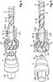
1 eine Schraube mit einer erfindungsgemäßen Hülse und einem erfindungsgemäßen Drehwerkzeug und ein handelsübliches Schrauberbit in einer perspektivischen Darstellung von einer Seite;2 die erfindungsgemäße Hülse neben der Schraube;3 die auf die Schraube aufgeklipste Hülse aus1 und2 ; und4 und5 die Schraube mit der aufgeklipsten, erfindungsgemäßen Hülse und dem erfindungsgemäßen, auf das Schrauberbit aufgesetzten erfindungsgemäßen Drehwerkzeug in unterschiedlichen Perspektiven.
1 a screw with a sleeve according to the invention and a turning tool according to the invention and a commercially available screwdriver bit in a perspective view from one side;2nd the sleeve according to the invention next to the screw;3rd the sleeve clipped onto the screw1 and2nd ; and4th and5 the screw with the clipped-on sleeve according to the invention and the turning tool according to the invention, placed on the screwdriver bit, in different perspectives.
Die Zeichnungen zeigen eine Schraube
Die Schraube
Zwischen dem Schraubenkopf
Die erfindungsgemäße Hülse
Die Unterbrechung
Durch die Unterbrechung
An den axialen Abschnitt der Hülse
An einem durchmessergrößeren Ende des unteren Widerlagers
Der das obere Widerlager
In dem axialen Abschnitt der Hülse
An einem Außenumfang des oberen Widerlagers
Das erfindungsgemäße Drehwerkzeug
Das erfindungsgemäße Drehwerkzeug
Das Durchgangsloch des Drehwerkzeugs
Das der Bitaufnahme ferne Ende des Schrauberbits
Ein dem Schraubenkopf
Für eine Abstandsbefestigung des nicht gezeichneten Bauteils wird die Schraube
BezugszeichenlisteReference symbol list
- DSDS
- SchaftdurchmesserShaft diameter
- DaDa
- Außendurchmesserouter diameter
- DiDi
- Kerndurchmessercore diameter
- 11
- Schraubescrew
- 22nd
- HülseSleeve
- 33rd
- DrehwerkzeugTurning tool
- 44th
- SchrauberbitScrewdriver bit
- 55
- SchraubengewindeScrew thread
- 66
- SchraubenkopfScrew head
- 77
- SchraubenwerkzeugsitzScrew tool seat
- 88th
- SchraubenschaftScrew shaft
- 99
- Unterseite des Schraubenkopfs
6 Bottom of the screw head6 - 1010th
- gewindeloser Schaftabschnittthreadless shaft section
- 1111
- Schaftabschnitt mit Frässchneiden
12 Shank section withmilling cutters 12 - 1212
- FrässchneidenMilling cutting
- 1313
- ClipClip
- 1414
- UnterbrechungInterruption
- 1515
- unteres Widerlagerlower abutment
- 1616
- oberes Widerlagerupper abutment
- 1717th
- HülsenwerkzeugsitzSleeve tool seat
- 18 18th
- Öffnungopening
- 1919th
- AußengewindeExternal thread
- 20, 21, 2220, 21, 22
- FrässchneideMilling cutter
- 2323
- InnensechskantHexagon socket
- 2424th
- SechskantschaftHexagon shaft
- 2525th
- Antriebselement des Schrauberbits
4 Drive element of the screwdriver bit4th - 2626
- Werkzeugkontur des Drehwerkzeugs
3 Tool contour of the turning tool3rd - DSDS
- SchaftdurchmesserShaft diameter
- DaThere
- Außendurchmesserouter diameter
- DiTue
- Kerndurchmessercore diameter
ZITATE ENTHALTEN IN DER BESCHREIBUNG QUOTES INCLUDE IN THE DESCRIPTION
Diese Liste der vom Anmelder aufgeführten Dokumente wurde automatisiert erzeugt und ist ausschließlich zur besseren Information des Lesers aufgenommen. Die Liste ist nicht Bestandteil der deutschen Patent- bzw. Gebrauchsmusteranmeldung. Das DPMA übernimmt keinerlei Haftung für etwaige Fehler oder Auslassungen.This list of documents listed by the applicant has been generated automatically and is only included for the better information of the reader. The list is not part of the German patent or utility model application. The DPMA assumes no liability for any errors or omissions.
Zitierte PatentliteraturPatent literature cited
- EP 0267161 A2 [0003]EP 0267161 A2 [0003]
Claims (7)
Translated fromGermanPriority Applications (2)
| Application Number | Priority Date | Filing Date | Title |
|---|---|---|---|
| DE102018131665.8ADE102018131665A1 (en) | 2018-12-11 | 2018-12-11 | Sleeve for developing a screw into a spacer screw, screw with such a sleeve and turning tool for screwing in the screw |
| EP19212885.8AEP3667107B1 (en) | 2018-12-11 | 2019-12-02 | Sleeve for forming a screw in a spacing screw, screw provided with such a sleeve, and rotary tool for screwing in the screw |
Applications Claiming Priority (1)
| Application Number | Priority Date | Filing Date | Title |
|---|---|---|---|
| DE102018131665.8ADE102018131665A1 (en) | 2018-12-11 | 2018-12-11 | Sleeve for developing a screw into a spacer screw, screw with such a sleeve and turning tool for screwing in the screw |
Publications (1)
| Publication Number | Publication Date |
|---|---|
| DE102018131665A1true DE102018131665A1 (en) | 2020-06-18 |
Family
ID=68762615
Family Applications (1)
| Application Number | Title | Priority Date | Filing Date |
|---|---|---|---|
| DE102018131665.8APendingDE102018131665A1 (en) | 2018-12-11 | 2018-12-11 | Sleeve for developing a screw into a spacer screw, screw with such a sleeve and turning tool for screwing in the screw |
Country Status (2)
| Country | Link |
|---|---|
| EP (1) | EP3667107B1 (en) |
| DE (1) | DE102018131665A1 (en) |
Families Citing this family (3)
| Publication number | Priority date | Publication date | Assignee | Title |
|---|---|---|---|---|
| US11808034B2 (en)* | 2019-03-08 | 2023-11-07 | Omg, Inc. | Floating connection fastening system |
| CN114086671B (en)* | 2021-11-15 | 2023-01-03 | 青岛东捷建设工程有限公司 | Anchoring structure for civil engineering |
| GB202204782D0 (en)* | 2022-04-01 | 2022-05-18 | Ohare Brendan | A fastener and a tool for operation thereof |
Citations (1)
| Publication number | Priority date | Publication date | Assignee | Title |
|---|---|---|---|---|
| EP0267161A2 (en) | 1986-11-03 | 1988-05-11 | Franz Spreiter | Screwing device |
Family Cites Families (6)
| Publication number | Priority date | Publication date | Assignee | Title |
|---|---|---|---|---|
| DE8126176U1 (en)* | 1981-09-09 | 1981-12-31 | Albert Berner GmbH & Co KG, 7118 Künzelsau | Spacer screw |
| DE4345193A1 (en)* | 1993-11-10 | 1995-05-11 | Karin Brueckl | Frame dowel |
| DE29603457U1 (en)* | 1995-07-21 | 1996-04-25 | Wolf, Stephan, 83209 Prien | Mounting sleeve for the variable mounting of objects |
| EP1184577A1 (en)* | 2000-09-01 | 2002-03-06 | Pro-Visa Int'l Corp. | Screw fastener with externally threaded anchoring ring |
| JP2004332845A (en)* | 2003-05-08 | 2004-11-25 | Wakai & Co Ltd | Screw |
| EP1972799A1 (en)* | 2007-03-21 | 2008-09-24 | Joker Industrial Co., Ltd. | Adjusting screw for door frames and window casings |
- 2018
- 2018-12-11DEDE102018131665.8Apatent/DE102018131665A1/enactivePending
- 2019
- 2019-12-02EPEP19212885.8Apatent/EP3667107B1/enactiveActive
Patent Citations (1)
| Publication number | Priority date | Publication date | Assignee | Title |
|---|---|---|---|---|
| EP0267161A2 (en) | 1986-11-03 | 1988-05-11 | Franz Spreiter | Screwing device |
Also Published As
| Publication number | Publication date |
|---|---|
| EP3667107B1 (en) | 2023-06-07 |
| EP3667107C0 (en) | 2023-06-07 |
| EP3667107A1 (en) | 2020-06-17 |
Similar Documents
| Publication | Publication Date | Title |
|---|---|---|
| DE69707679T2 (en) | SCREW FOR CORTICAL BONES | |
| DE2209688B2 (en) | INSERT NUT | |
| DE102011086491B4 (en) | screw | |
| EP3667107B1 (en) | Sleeve for forming a screw in a spacing screw, screw provided with such a sleeve, and rotary tool for screwing in the screw | |
| DE102020107225A1 (en) | Plasterboard anchor and combination of the plasterboard anchor with a drilling and turning tool | |
| DE102004020000B4 (en) | Suspension element | |
| WO2016081964A1 (en) | Machining tool | |
| DE102012108779A1 (en) | profile connection | |
| DE10333194B4 (en) | Deburring tool with knife quick coupler | |
| DE2605310A1 (en) | BOLT ELEMENT FOR FIXING IN A BASE HOLE | |
| EP3016770B1 (en) | Exchangeable-head system for metal working | |
| DE2708025A1 (en) | ADJUSTABLE TOOL HOLDER FOR A DRILLING SPINDLE | |
| EP2811178A1 (en) | Expansion dowel with screw | |
| DE2609186A1 (en) | SAFETY NUT | |
| DE102006006440B4 (en) | Method for releasing a riveted joint | |
| EP4222324B1 (en) | System and method for fastening insulating material | |
| DE202007017663U1 (en) | fixture | |
| DE69534050T2 (en) | Anchoring element for brittle material | |
| DE60106803T2 (en) | punching device | |
| DE1077920B (en) | Thread insert | |
| DE102011121089A1 (en) | Device for supporting and sealing pipe in pipe outlet or fitting, has mounting sleeve which overlaps and corresponds to nut in screwing or positive-locking direction and enables freewheel in opposite direction | |
| DE8335453U1 (en) | Center drill for a hollow core bit | |
| DE102024112582A1 (en) | Drywall anchor and method for installing the drywall anchor | |
| DE102023111533A1 (en) | insulation anchor | |
| DE8302613U1 (en) | Screw and nut locking |
Legal Events
| Date | Code | Title | Description |
|---|---|---|---|
| R012 | Request for examination validly filed |