DE102018128783A1 - Measuring device for a charging device and charging device - Google Patents
Measuring device for a charging device and charging deviceDownload PDFInfo
- Publication number
- DE102018128783A1 DE102018128783A1DE102018128783.6ADE102018128783ADE102018128783A1DE 102018128783 A1DE102018128783 A1DE 102018128783A1DE 102018128783 ADE102018128783 ADE 102018128783ADE 102018128783 A1DE102018128783 A1DE 102018128783A1
- Authority
- DE
- Germany
- Prior art keywords
- measuring device
- charging
- current
- voltage
- circuit board
- Prior art date
- Legal status (The legal status is an assumption and is not a legal conclusion. Google has not performed a legal analysis and makes no representation as to the accuracy of the status listed.)
- Granted
Links
Images


Classifications
- H—ELECTRICITY
- H02—GENERATION; CONVERSION OR DISTRIBUTION OF ELECTRIC POWER
- H02J—CIRCUIT ARRANGEMENTS OR SYSTEMS FOR SUPPLYING OR DISTRIBUTING ELECTRIC POWER; SYSTEMS FOR STORING ELECTRIC ENERGY
- H02J7/00—Circuit arrangements for charging or depolarising batteries or for supplying loads from batteries
- H02J7/0042—Circuit arrangements for charging or depolarising batteries or for supplying loads from batteries characterised by the mechanical construction
- B—PERFORMING OPERATIONS; TRANSPORTING
- B60—VEHICLES IN GENERAL
- B60L—PROPULSION OF ELECTRICALLY-PROPELLED VEHICLES; SUPPLYING ELECTRIC POWER FOR AUXILIARY EQUIPMENT OF ELECTRICALLY-PROPELLED VEHICLES; ELECTRODYNAMIC BRAKE SYSTEMS FOR VEHICLES IN GENERAL; MAGNETIC SUSPENSION OR LEVITATION FOR VEHICLES; MONITORING OPERATING VARIABLES OF ELECTRICALLY-PROPELLED VEHICLES; ELECTRIC SAFETY DEVICES FOR ELECTRICALLY-PROPELLED VEHICLES
- B60L53/00—Methods of charging batteries, specially adapted for electric vehicles; Charging stations or on-board charging equipment therefor; Exchange of energy storage elements in electric vehicles
- B60L53/10—Methods of charging batteries, specially adapted for electric vehicles; Charging stations or on-board charging equipment therefor; Exchange of energy storage elements in electric vehicles characterised by the energy transfer between the charging station and the vehicle
- B60L53/11—DC charging controlled by the charging station, e.g. mode 4
- B—PERFORMING OPERATIONS; TRANSPORTING
- B60—VEHICLES IN GENERAL
- B60L—PROPULSION OF ELECTRICALLY-PROPELLED VEHICLES; SUPPLYING ELECTRIC POWER FOR AUXILIARY EQUIPMENT OF ELECTRICALLY-PROPELLED VEHICLES; ELECTRODYNAMIC BRAKE SYSTEMS FOR VEHICLES IN GENERAL; MAGNETIC SUSPENSION OR LEVITATION FOR VEHICLES; MONITORING OPERATING VARIABLES OF ELECTRICALLY-PROPELLED VEHICLES; ELECTRIC SAFETY DEVICES FOR ELECTRICALLY-PROPELLED VEHICLES
- B60L53/00—Methods of charging batteries, specially adapted for electric vehicles; Charging stations or on-board charging equipment therefor; Exchange of energy storage elements in electric vehicles
- B60L53/30—Constructional details of charging stations
- B60L53/31—Charging columns specially adapted for electric vehicles
- B—PERFORMING OPERATIONS; TRANSPORTING
- B60—VEHICLES IN GENERAL
- B60L—PROPULSION OF ELECTRICALLY-PROPELLED VEHICLES; SUPPLYING ELECTRIC POWER FOR AUXILIARY EQUIPMENT OF ELECTRICALLY-PROPELLED VEHICLES; ELECTRODYNAMIC BRAKE SYSTEMS FOR VEHICLES IN GENERAL; MAGNETIC SUSPENSION OR LEVITATION FOR VEHICLES; MONITORING OPERATING VARIABLES OF ELECTRICALLY-PROPELLED VEHICLES; ELECTRIC SAFETY DEVICES FOR ELECTRICALLY-PROPELLED VEHICLES
- B60L53/00—Methods of charging batteries, specially adapted for electric vehicles; Charging stations or on-board charging equipment therefor; Exchange of energy storage elements in electric vehicles
- B60L53/60—Monitoring or controlling charging stations
- B60L53/66—Data transfer between charging stations and vehicles
- B60L53/665—Methods related to measuring, billing or payment
- G—PHYSICS
- G01—MEASURING; TESTING
- G01R—MEASURING ELECTRIC VARIABLES; MEASURING MAGNETIC VARIABLES
- G01R1/00—Details of instruments or arrangements of the types included in groups G01R5/00 - G01R13/00 and G01R31/00
- G01R1/20—Modifications of basic electric elements for use in electric measuring instruments; Structural combinations of such elements with such instruments
- G01R1/203—Resistors used for electric measuring, e.g. decade resistors standards, resistors for comparators, series resistors, shunts
- H—ELECTRICITY
- H02—GENERATION; CONVERSION OR DISTRIBUTION OF ELECTRIC POWER
- H02J—CIRCUIT ARRANGEMENTS OR SYSTEMS FOR SUPPLYING OR DISTRIBUTING ELECTRIC POWER; SYSTEMS FOR STORING ELECTRIC ENERGY
- H02J7/00—Circuit arrangements for charging or depolarising batteries or for supplying loads from batteries
- H02J7/0047—Circuit arrangements for charging or depolarising batteries or for supplying loads from batteries with monitoring or indicating devices or circuits
- G—PHYSICS
- G01—MEASURING; TESTING
- G01R—MEASURING ELECTRIC VARIABLES; MEASURING MAGNETIC VARIABLES
- G01R31/00—Arrangements for testing electric properties; Arrangements for locating electric faults; Arrangements for electrical testing characterised by what is being tested not provided for elsewhere
- G01R31/005—Testing of electric installations on transport means
- G01R31/006—Testing of electric installations on transport means on road vehicles, e.g. automobiles or trucks
- Y—GENERAL TAGGING OF NEW TECHNOLOGICAL DEVELOPMENTS; GENERAL TAGGING OF CROSS-SECTIONAL TECHNOLOGIES SPANNING OVER SEVERAL SECTIONS OF THE IPC; TECHNICAL SUBJECTS COVERED BY FORMER USPC CROSS-REFERENCE ART COLLECTIONS [XRACs] AND DIGESTS
- Y02—TECHNOLOGIES OR APPLICATIONS FOR MITIGATION OR ADAPTATION AGAINST CLIMATE CHANGE
- Y02T—CLIMATE CHANGE MITIGATION TECHNOLOGIES RELATED TO TRANSPORTATION
- Y02T10/00—Road transport of goods or passengers
- Y02T10/60—Other road transportation technologies with climate change mitigation effect
- Y02T10/70—Energy storage systems for electromobility, e.g. batteries
- Y—GENERAL TAGGING OF NEW TECHNOLOGICAL DEVELOPMENTS; GENERAL TAGGING OF CROSS-SECTIONAL TECHNOLOGIES SPANNING OVER SEVERAL SECTIONS OF THE IPC; TECHNICAL SUBJECTS COVERED BY FORMER USPC CROSS-REFERENCE ART COLLECTIONS [XRACs] AND DIGESTS
- Y02—TECHNOLOGIES OR APPLICATIONS FOR MITIGATION OR ADAPTATION AGAINST CLIMATE CHANGE
- Y02T—CLIMATE CHANGE MITIGATION TECHNOLOGIES RELATED TO TRANSPORTATION
- Y02T10/00—Road transport of goods or passengers
- Y02T10/60—Other road transportation technologies with climate change mitigation effect
- Y02T10/7072—Electromobility specific charging systems or methods for batteries, ultracapacitors, supercapacitors or double-layer capacitors
- Y—GENERAL TAGGING OF NEW TECHNOLOGICAL DEVELOPMENTS; GENERAL TAGGING OF CROSS-SECTIONAL TECHNOLOGIES SPANNING OVER SEVERAL SECTIONS OF THE IPC; TECHNICAL SUBJECTS COVERED BY FORMER USPC CROSS-REFERENCE ART COLLECTIONS [XRACs] AND DIGESTS
- Y02—TECHNOLOGIES OR APPLICATIONS FOR MITIGATION OR ADAPTATION AGAINST CLIMATE CHANGE
- Y02T—CLIMATE CHANGE MITIGATION TECHNOLOGIES RELATED TO TRANSPORTATION
- Y02T90/00—Enabling technologies or technologies with a potential or indirect contribution to GHG emissions mitigation
- Y02T90/10—Technologies relating to charging of electric vehicles
- Y02T90/12—Electric charging stations
- Y—GENERAL TAGGING OF NEW TECHNOLOGICAL DEVELOPMENTS; GENERAL TAGGING OF CROSS-SECTIONAL TECHNOLOGIES SPANNING OVER SEVERAL SECTIONS OF THE IPC; TECHNICAL SUBJECTS COVERED BY FORMER USPC CROSS-REFERENCE ART COLLECTIONS [XRACs] AND DIGESTS
- Y02—TECHNOLOGIES OR APPLICATIONS FOR MITIGATION OR ADAPTATION AGAINST CLIMATE CHANGE
- Y02T—CLIMATE CHANGE MITIGATION TECHNOLOGIES RELATED TO TRANSPORTATION
- Y02T90/00—Enabling technologies or technologies with a potential or indirect contribution to GHG emissions mitigation
- Y02T90/10—Technologies relating to charging of electric vehicles
- Y02T90/14—Plug-in electric vehicles
- Y—GENERAL TAGGING OF NEW TECHNOLOGICAL DEVELOPMENTS; GENERAL TAGGING OF CROSS-SECTIONAL TECHNOLOGIES SPANNING OVER SEVERAL SECTIONS OF THE IPC; TECHNICAL SUBJECTS COVERED BY FORMER USPC CROSS-REFERENCE ART COLLECTIONS [XRACs] AND DIGESTS
- Y02—TECHNOLOGIES OR APPLICATIONS FOR MITIGATION OR ADAPTATION AGAINST CLIMATE CHANGE
- Y02T—CLIMATE CHANGE MITIGATION TECHNOLOGIES RELATED TO TRANSPORTATION
- Y02T90/00—Enabling technologies or technologies with a potential or indirect contribution to GHG emissions mitigation
- Y02T90/10—Technologies relating to charging of electric vehicles
- Y02T90/16—Information or communication technologies improving the operation of electric vehicles
- Y02T90/167—Systems integrating technologies related to power network operation and communication or information technologies for supporting the interoperability of electric or hybrid vehicles, i.e. smartgrids as interface for battery charging of electric vehicles [EV] or hybrid vehicles [HEV]
- Y—GENERAL TAGGING OF NEW TECHNOLOGICAL DEVELOPMENTS; GENERAL TAGGING OF CROSS-SECTIONAL TECHNOLOGIES SPANNING OVER SEVERAL SECTIONS OF THE IPC; TECHNICAL SUBJECTS COVERED BY FORMER USPC CROSS-REFERENCE ART COLLECTIONS [XRACs] AND DIGESTS
- Y04—INFORMATION OR COMMUNICATION TECHNOLOGIES HAVING AN IMPACT ON OTHER TECHNOLOGY AREAS
- Y04S—SYSTEMS INTEGRATING TECHNOLOGIES RELATED TO POWER NETWORK OPERATION, COMMUNICATION OR INFORMATION TECHNOLOGIES FOR IMPROVING THE ELECTRICAL POWER GENERATION, TRANSMISSION, DISTRIBUTION, MANAGEMENT OR USAGE, i.e. SMART GRIDS
- Y04S30/00—Systems supporting specific end-user applications in the sector of transportation
- Y04S30/10—Systems supporting the interoperability of electric or hybrid vehicles
- Y04S30/14—Details associated with the interoperability, e.g. vehicle recognition, authentication, identification or billing
Landscapes
- Engineering & Computer Science (AREA)
- Power Engineering (AREA)
- Transportation (AREA)
- Mechanical Engineering (AREA)
- Physics & Mathematics (AREA)
- General Physics & Mathematics (AREA)
- Charge And Discharge Circuits For Batteries Or The Like (AREA)
- Secondary Cells (AREA)
- Electric Propulsion And Braking For Vehicles (AREA)
Abstract
Translated fromGerman
Description
Translated fromGermanDie vorliegende Erfindung betrifft eine Messeinrichtung für eine Ladeeinrichtung zum Laden eines Fahrzeugs mit einem elektrischen Antrieb mit Gleichstrom, wobei die Ladeeinrichtung eine elektrische Verbindungseinrichtung zum Verbinden mit dem elektrischen Fahrzeug aufweist, die Messeinrichtung umfassend eine Strommesseinrichtung mit einem Shunt und einem Spannungsmesser zum Messen einer Spannung an dem Shunt zur Bestimmung eines Ladestroms durch einen ersten Stromleiter der Verbindungseinrichtung, und eine Spannungsmesseinrichtung zum Messen einer Ladespannung zwischen dem ersten Stromleiter und einem zweiten Stromleiter der Verbindungseinrichtung, wobei die Messeinrichtung eine Leiterplatte aufweist, auf der die Strommesseinrichtung und die Spannungsmesseinrichtung angeordnet sind.The present invention relates to a measuring device for a charging device for charging a vehicle with an electric drive with direct current, the charging device having an electrical connecting device for connecting to the electric vehicle, the measuring device comprising a current measuring device with a shunt and a voltmeter for measuring a voltage the shunt for determining a charging current through a first current conductor of the connecting device, and a voltage measuring device for measuring a charging voltage between the first current conductor and a second current conductor of the connecting device, the measuring device having a printed circuit board on which the current measuring device and the voltage measuring device are arranged.
Die vorliegende Erfindung betrifft außerdem eine Ladeeinrichtung zum Laden eines Fahrzeugs mit einem elektrischen Antrieb mit Gleichstrom, wobei die Ladeeinrichtung eine elektrische Verbindungseinrichtung zum Verbinden mit dem elektrischen Fahrzeug und eine obige Messeinrichtung aufweist, wobei die Messeinrichtung angeordnet ist, um einen Strom und eine Spannung der Verbindungseinrichtung zu messen.The present invention also relates to a charging device for charging a vehicle with an electric drive with direct current, the charging device having an electrical connecting device for connecting to the electric vehicle and an above measuring device, the measuring device being arranged to measure a current and a voltage of the connecting device to eat.
Beim Laden und insbesondere beim Schnellladen von Fahrzeugen mit elektrischen Antrieben mit hohen Gleichspannungen und -strömen ist es erforderlich, große elektrische Leistungen bereitzustellen. Ladespannungen von bis zu tausend Volt und/oder Ladeströme von mehreren hundert Ampere können bei solchen Schnellladevorgängen aktuell auftreten. Für zukünftige Anwendungen sind auch Spannungen von über tausend Volt und Ströme von über tausend Ampere möglich.When charging and in particular when charging vehicles with electrical drives with high DC voltages and currents, it is necessary to provide large electrical outputs. Charging voltages of up to a thousand volts and / or charging currents of several hundred amperes can currently occur in such rapid charging processes. Voltages of over a thousand volts and currents of over a thousand amperes are also possible for future applications.
Zur Ladeinfrastruktur gehören typischerweise eine Ladeeinrichtung, meist nach der Art einer Ladesäule, eine Kühlungseinheit und eine Leistungselektronik. Dabei werden häufig mehrere Ladesäulen gemeinsam aufgestellt. Ein optionales Backend kann jede Ladesäule oder bei gemeinsamer Aufstellung jeden Ladepark mit einer Zentrale verbinden.The charging infrastructure typically includes a charging device, usually in the manner of a charging station, a cooling unit and power electronics. Often, several charging stations are set up together. An optional backend can connect each charging station or, if installed together, each charging park to a control center.
Wichtig beim Laden von Fahrzeugen mit elektrischen Antrieben ist eine korrekte Abrechnung von übertragener elektrischer Energie. Dazu ist es prinzipiell erforderlich, die großen Gleichspannungen und -ströme zuverlässig zu messen. Dadurch kann die an das jeweilige Fahrzeug beim Laden übertragene Energie abgerechnet werden, damit sich der Betrieb von solchen (Gleichstrom-)Ladeeinrichtungen lohnt. Dies ist jedoch in der Praxis schwierig durchzuführen. Heutige Ladesäulen messen meist eine eingangsseitig an die Ladesäule übertragene AC-Eingangsenergie, weil diese zertifiziert bestimmt werden kann. Diese gegenüber einem Kunden abzurechnen würde jedoch bedeuten, dass in der Ladesäule anfallende Verluste dem Kunden mit in Rechnung gestellt werden. Daher wird die Energie teilweise verschenkt oder über Pauschalen oder Parkplatzmiete vor den Ladesäulen abgerechnet. Dies ist meist sowohl für den Betreiber einer Ladeeinrichtung wie auch für den Kunden unerwünscht.When charging vehicles with electric drives, it is important that the transferred electrical energy is billed correctly. In principle, this requires reliably measuring the large DC voltages and currents. As a result, the energy transferred to the respective vehicle when charging is billed so that the operation of such (direct current) charging devices is worthwhile. However, this is difficult to do in practice. Today's charging stations usually measure an AC input energy transmitted to the charging station on the input side, because this can be determined in a certified manner. However, billing these to a customer would mean that losses incurred in the charging station are also charged to the customer. This is why some of the energy is given away or billed via flat rates or parking space rental in front of the charging stations. This is usually undesirable both for the operator of a charging device and for the customer.
Um die an das Fahrzeug übertragene Energie zu bestimmen, ist es erforderlich, sowohl Spannung als auch Strom während des Ladevorgangs ausgangsseitig an der Ladeeinrichtung zu bestimmen. Zur genauen Strommessung werden in Ladesäulen bisher Stromwandler eingesetzt, die auf dem Hall-Effekt, also der Messung eines einen Leiter umgebenden Magnetfeldes, beruhen. Die Verwendung von Stromwandlern ist aber ausgehend von verschiedenen, möglichen Kombinationen aus Strom und Spannung problematisch. Um einen entsprechenden Messbereich abdecken zu können, kann die Messgenauigkeit bei kleineren Werten von Strom und Spannung zu gering sein. Dies ist zusätzlich problematisch, da die Fahrzeuge verschiedene Ladecharakteristika aufweisen und beispielsweise abhängig von einem aktuellen Ladestand beliebige Spannungen und Ströme abrufen können. Ladestrom und Ladespannung hängen somit nicht nur vom Fahrzeug als solchem ab, sondern können sich während des Ladevorgangs kontinuierlich ändern. Ladestrom und Ladespannung müssen daher während des Ladevorgangs kontinuierlich überwacht werden.In order to determine the energy transmitted to the vehicle, it is necessary to determine both the voltage and the current on the output side of the charging device during the charging process. To date, current transformers based on the Hall effect, that is to say the measurement of a magnetic field surrounding a conductor, have been used in charging stations for accurate current measurement. The use of current transformers is problematic, however, based on various possible combinations of current and voltage. In order to be able to cover a corresponding measuring range, the measuring accuracy may be too low for smaller values of current and voltage. This is additionally problematic since the vehicles have different charging characteristics and can, for example, call up any voltages and currents depending on a current charge level. Charging current and charging voltage therefore not only depend on the vehicle as such, but can change continuously during the charging process. The charging current and charging voltage must therefore be continuously monitored during the charging process.
Im Stand der Technik ist allgemein bekannt, Gleichstrommesser mit einem Shunt zu verwenden, um einen Gleichstrom zu bestimmen. Dazu wird eine Spannung über dem Shunt gemessen und daraus der durch den Shunt fließende Strom ermittelt. In Fahrzeugen mit elektrischen Antrieben werden bereits teilweise Shunts eingesetzt, um den Ladestrom während des Ladevorgangs zu messen. Dadurch kann der Ladevorgang einer Batterie des Fahrzeugs überwacht werden.It is well known in the art to use DC meters with a shunt to determine a DC current. For this purpose, a voltage across the shunt is measured and the current flowing through the shunt is determined. Shunts are already partially used in vehicles with electric drives to measure the charging current during the charging process. This enables the charging process of a battery in the vehicle to be monitored.
Der Gleichstrom und die Gleichspannung bei großen DC-Leistungen müssen an den Ladesäulen präzise gemessen werden, um die übertragene Energie zu bestimmen und diese abrechnen zu können. Dabei kann es durch die häufige Benutzung der Ladeeinrichtung, insbesondere eine Bewegung der Verbindungseinrichtung, zu mechanischen Schäden kommen. Insbesondere kann die Messeinrichtung durch eine Bewegung von Stromleitern der Verbindungseinrichtung oder durch aus Bewegung insbesondere der Verbindungseinrichtung resultierenden Erschütterungen beschädigt werden, oder Ihre Verbindung mit den Stromleitern wird beschädigt. Dies kann dazu führen, dass die Messeinrichtung ausfällt und die Ladeeinrichtung insgesamt nicht weiter nutzbar ist. Dies betrifft beispielsweise auch Verbindungsstecker, welche einzelne Komponenten der Messeinrichtung untereinander oder die Messeinrichtung insgesamt mit der Ladeeinrichtung verbinden. Hier ist es zu verhindern, dass sich die Verbindungsstecker im Betrieb lösen, um eine korrekte Funktion der Ladeeinrichtung auch über einen längeren Zeitraum zu gewährleisten und Aufwand für Wartung und Reparatur gering zu halten.The direct current and direct voltage for large DC powers must be measured precisely on the charging stations in order to determine the transmitted energy and to be able to bill for this. Frequent use of the charging device, in particular movement of the connecting device, can result in mechanical damage. In particular, the measuring device can be damaged by movement of current conductors of the connection device or by vibrations resulting from movement, in particular, of the connection device, or your connection to the current conductors is damaged. This can lead to the failure of the measuring device and the charging device as a whole is usable. This also applies, for example, to connecting plugs which connect individual components of the measuring device to one another or the measuring device as a whole to the charging device. It is to be prevented here that the connecting plugs become loose during operation in order to ensure correct functioning of the charging device even over a longer period of time and to keep maintenance and repair work to a minimum.
Außerdem ist es wichtig, einzelne Komponenten leicht anbringen oder auch austauschen zu können. Dies ist insbesondere im Zusammenhang mit einer Verbesserung bestehender Ladesäulen wichtig, um die Akzeptanz von Elektrofahrzeugen insgesamt steigern zu können.It is also important to be able to easily attach or replace individual components. This is particularly important in connection with the improvement of existing charging stations in order to be able to increase the acceptance of electric vehicles overall.
Dabei soll außerdem eine kostengünstige Implementierung erfolgen, um Elektrofahrzeuge und ihre Infrastruktur für einen Massenbetrieb verfügbar zu machen.In addition, an inexpensive implementation is to take place in order to make electric vehicles and their infrastructure available for mass operation.
In diesem Zusammenhang ist aus der
Die
Gemäß der
Die
Außerdem ist aus der
Ausgehend von dem oben genannten Stand der Technik liegt der Erfindung somit die Aufgabe zugrunde, eine Messeinrichtung für eine Ladeeinrichtung zum Laden eines Fahrzeugs mit einem elektrischen Antrieb mit Gleichstrom und eine Ladeeinrichtung der oben genannten Art anzugeben, die eine einfache und dauerhafte Bestimmung von Ladestrom und Ladespannung ermöglicht und wobei die Messeinrichtung einfach und zuverlässig in die Ladeeinrichtung integrierbar ist.Proceeding from the above-mentioned prior art, the invention is therefore based on the object of specifying a measuring device for a charging device for charging a vehicle with an electric drive with direct current and a charging device of the type mentioned above, which enables simple and permanent determination of the charging current and charging voltage enables and wherein the measuring device can be easily and reliably integrated into the charging device.
Die Lösung der Aufgabe erfolgt erfindungsgemäß durch die Merkmale der unabhängigen Ansprüche. Vorteilhafte Ausgestaltungen der Erfindung sind in den Unteransprüchen angegeben.The object is achieved according to the invention by the features of the independent claims. Advantageous embodiments of the invention are specified in the subclaims.
Erfindungsgemäß ist somit eine Messeinrichtung für eine Ladeeinrichtung zum Laden eines Fahrzeugs mit einem elektrischen Antrieb mit Gleichstrom vorgesehen, wobei die Ladeeinrichtung eine elektrische Verbindungseinrichtung zum Verbinden mit dem elektrischen Fahrzeug aufweist, die Messeinrichtung umfassend eine Strommesseinrichtung mit einem Shunt und einem Spannungsmesser zum Messen einer Spannung an dem Shunt zur Bestimmung eines Ladestroms durch einen ersten Stromleiter der Verbindungseinrichtung, und eine Spannungsmesseinrichtung zum Messen einer Ladespannung zwischen dem ersten Stromleiter und einem zweiten Stromleiter der Verbindungseinrichtung, wobei die Messeinrichtung eine Leiterplatte aufweist, auf der die Strommesseinrichtung und die Spannungsmesseinrichtung angeordnet sind, und die Messeinrichtung ein elektrisch leitendes Verbindungselement, das mit der Leiterplatte verbunden ist, zur elektrischen Verbindung der Spannungsmesseinrichtung mit dem zweiten Stromleiter aufweist.According to the invention, a measuring device for a charging device for charging a vehicle with an electric drive with direct current is thus provided, the charging device having an electrical connection device for connecting to the electric vehicle, the measuring device comprising a current measuring device with a shunt and a voltmeter for measuring a voltage the shunt for determining a charging current through a first current conductor of the connecting device, and a voltage measuring device for measuring a charging voltage between the first current conductor and a second current conductor of the connecting device, the measuring device having a printed circuit board on which the current measuring device and the voltage measuring device are arranged, and the Measuring device has an electrically conductive connecting element, which is connected to the printed circuit board, for the electrical connection of the voltage measuring device to the second current conductor t.
Erfindungsgemäß ist außerdem eine Ladeeinrichtung zum Laden eines Fahrzeugs mit einem elektrischen Antrieb mit Gleichstrom vorgesehen, wobei die Ladeeinrichtung eine elektrische Verbindungseinrichtung zum Verbinden mit dem elektrischen Fahrzeug und eine obige Messeinrichtung aufweist, wobei die Messeinrichtung angeordnet ist, um einen Strom und eine Spannung der Verbindungseinrichtung zu messen.According to the invention, a charging device for charging a vehicle with an electric drive with direct current is also provided, the charging device having an electrical connecting device for connecting to the electric vehicle and an above measuring device, the measuring device being arranged to supply a current and a voltage to the connecting device measure up.
Grundidee der vorliegenden Erfindung ist es also, die Messeinrichtung mit dem Verbindungselement als starre Einheit bereitzustellen. Dies ermöglicht eine einfache Montage der Messeinrichtung und die Messeinrichtung kann als kompakte Einheit bereitgestellt werden. Die Befestigung der Messeinrichtung kann dadurch eine geringe Anfälligkeit für Störungen aufweisen. Die Spannungsmessung kann über das Verbindungselement und den Shunt, der integral in der Messeinrichtung vorhanden ist und in den ersten Stromleiter eingebracht wird, erfolgen. Zusätzliche Kontakte sind nicht erforderlich. Das Verbindungselement kann dabei ein prinzipiell beliebiges elektrisch leitendes Element sein.The basic idea of the present invention is therefore to provide the measuring device with the connecting element as a rigid unit. This enables simple mounting of the measuring device and the measuring device can be provided as a compact unit. The attachment of the measuring device can therefore have a low susceptibility to faults. The voltage measurement can take place via the connecting element and the shunt, which is integrally present in the measuring device and is introduced into the first current conductor. Additional contacts are not required. The connecting element can in principle be any electrically conductive element.
Die Ladeeinrichtung ist beispielsweise eine Ladesäule zum Laden des Fahrzeugs. Das Fahrzeug kann dabei ausschließlich einen elektrischen Antrieb aufweisen, oder als sogenanntes Hybridfahrzeug einen zusätzlichen Antrieb aufweisen.The charging device is, for example, a charging station for charging the vehicle. The vehicle can have only an electric drive, or an additional drive as a so-called hybrid vehicle.
Die Messeinrichtung umfasst die Strommesseinrichtung und die Spannungsmesseinrichtung, so dass darauf basierend eine über die Verbindungseinrichtung übertragene Energiemenge einfach bestimmt werden kann. Durch die Anbringung der Messeinrichtung an bzw. in der Verbindungseinrichtung wird sichergestellt, dass eine zum Laden an das jeweilige Fahrzeug abgegebene Energiemenge korrekt bestimmt werden kann.The measuring device comprises the current measuring device and the voltage measuring device, so that based on this an amount of energy transmitted via the connecting device can be easily determined. The attachment of the measuring device to or in the connecting device ensures that an amount of energy delivered to the respective vehicle for charging can be correctly determined.
Die Messeinrichtung kann für den Betrieb der Strommesseinrichtung wie auch der Spannungsmesseinrichtung eine Energieversorgungseinrichtung umfassen. Die Energieversorgungseinrichtung stellt dazu typischerweise ausgangsseitig einen konstanten Gleichspannungspegel zur Verfügung. Eingangsseitig kann die Energieversorgungseinrichtung von den Stromleitern oder einem Netzteil gespeist werden.The measuring device can comprise an energy supply device for operating the current measuring device as well as the voltage measuring device. For this purpose, the energy supply device typically provides a constant DC voltage level on the output side. On the input side, the energy supply device can be supplied by the current conductors or a power supply unit.
Die Messeinrichtung kann eine Datenschnittstelle aufweisen, über die bei der Strom- und Spannungsmessung ermittelte Werte übertragen werden können. Die Datenschnittstelle kann beispielsweise zur Verbindung mit einem CAN-Bus ausgeführt sein. Aus den von der Messeinrichtung gelieferten Werten für Strom und Spannung kann unter Berücksichtigung der Zeit eine beim Laden an das Fahrzeug über die Verbindungseinrichtung übertragene Energiemenge ermittelt werden.The measuring device can have a data interface, via which values determined during the current and voltage measurement can be transmitted. The data interface can, for example, be designed for connection to a CAN bus. From the values for current and voltage supplied by the measuring device, an amount of energy transmitted to the vehicle when charging via the connecting device can be determined taking into account the time.
Der Shunt wird in dem ersten Stromleiter eingebracht und mit diesem kontaktiert bzw. leitend verbunden. Die Strommesseinrichtung umfasst den Shunt als Messwiderstand, der einen sehr kleinen Widerstandswert von typischerweise weniger als einem Ohm aufweist. Eine genaue Kenntnis des Widerstandswerts des Shunts ermöglicht eine exakte Bestimmung eines Stroms durch den Shunt. Der Ladestrom kann bestimmt werden, indem die Spannung über dem Shunt gemessen wird, wobei die Spannung prinzipiell proportional zu dem Ladestrom ist. Beispielsweise können Ströme in einem Bereich von +/-500 A mit einem Fehler von 0,4% über den Shunt sehr genau bestimmt werden. Durch die Strommessung mit dem Shunt ist die Messung gut gegen externe elektromagnetische Felder geschützt. Die Strommessung mit dem Shunt bietet damit Vorteile gegenüber Messungen von Magnetfeldern mit Hall-Sensoren in z.B. LEM-Wandlern. Diese sind meist groß und müssen den Stromleiter umgreifen. Die Messeinrichtung kann somit auch ohne bewegliche Teile bereitgestellt werden, wodurch sie vor Verschleiß geschützt ist.The shunt is introduced into the first conductor and contacted or conductively connected to it. The current measuring device comprises the shunt as a measuring resistor, which has a very small resistance value of typically less than one ohm. A precise knowledge of the resistance value of the shunt enables an exact determination of a current through the shunt. The charging current can be determined by measuring the voltage across the shunt, the voltage being in principle proportional to the charging current. For example, currents in a range of +/- 500 A with an error of 0.4% can be determined very precisely via the shunt. By measuring the current with the shunt, the measurement is well protected against external electromagnetic fields. The current measurement with the shunt thus offers advantages over Measurements of magnetic fields with Hall sensors in LEM converters, for example. These are usually large and have to encompass the conductor. The measuring device can thus also be provided without moving parts, as a result of which it is protected against wear.
Die Messeinrichtung kann einen Kontakt des Shunts als Massepotential verwenden. Insbesondere wird eine negative Seite des Shunts als Massepotential verwendet.The measuring device can use a contact of the shunt as a ground potential. In particular, a negative side of the shunt is used as the ground potential.
In vorteilhafter Ausgestaltung der Erfindung ist das elektrische Verbindungselement mit einer Schraubverbindung an der Leiterplatte angebracht. Schraubverbindungen sind einfach herzustellen und ermöglichen eine stabile und zuverlässige Verbindung. Für Wartung und Austausch kann die Schraubverbindung einfach gelöst werden.In an advantageous embodiment of the invention, the electrical connecting element is attached to the printed circuit board with a screw connection. Screw connections are easy to make and enable a stable and reliable connection. The screw connection can be easily loosened for maintenance and replacement.
In vorteilhafter Ausgestaltung der Erfindung ist das elektrische Verbindungselement mit der Leiterplatte verlötet. Das Verlöten ermöglicht ein Herstellen einer elektrisch gut leitenden Verbindung. Die Lötverbindung kann beispielsweise nach dem Bestücken der Leiterplatte in einem einzigen Lötschritt mit hergestellt werden, so dass das Verbindungselement mit geringem Aufwand angebracht werden kann.In an advantageous embodiment of the invention, the electrical connection element is soldered to the circuit board. The soldering enables a good electrical connection to be made. The soldered connection can, for example, be produced in a single soldering step after the circuit board has been populated, so that the connecting element can be attached with little effort.
In vorteilhafter Ausgestaltung der Erfindung weist das elektrische Verbindungselement einen Steckverbinder zur steckenden Verbindung mit einer korrespondierenden Steckverbinderaufnahme auf der Leiterplatte auf. Somit kann das Verbindungselement einfach mit der Leiterplatte verbunden oder bei Bedarf wieder davon entfernt werden. Vorzugsweise ist die Verbindung aus Steckverbinder und Steckverbinderaufnahme innerhalb eines die Messeinrichtung umschließenden Gehäuses angeordnet, wodurch die Verbindung gut geschützt ist. Das umschließende Gehäuse dient dabei einerseits zum Schutz der darin aufgenommenen Strommesseinrichtung und der Spannungsmesseinrichtung, und andererseits zur Bereitstellung einer integralen und kompakten Messeinrichtung. Das Gehäuse ist vorzugsweise aus einem nicht elektrisch leitenden Material ausgeführt, beispielsweise aus einem Kunststoffmaterial.In an advantageous embodiment of the invention, the electrical connecting element has a plug connector for the plug-in connection with a corresponding plug connector receptacle on the printed circuit board. Thus, the connecting element can easily be connected to the circuit board or removed from it again if necessary. The connector and connector receptacle connection is preferably arranged within a housing enclosing the measuring device, as a result of which the connection is well protected. The enclosing housing serves on the one hand to protect the current measuring device and the voltage measuring device contained therein, and on the other hand to provide an integral and compact measuring device. The housing is preferably made of a non-electrically conductive material, for example a plastic material.
In vorteilhafter Ausgestaltung der Erfindung weist das elektrische Verbindungselement an seinem freien Ende wenigstens ein Durchgangsloch zum Herstellen einer Schraubverbindung mit dem zweiten Stromleiter auf. Schraubverbindungen sind einfach herzustellen und ermöglichen eine stabile und zuverlässige Verbindung mit dem zweiten Stromleiter. Für Wartung und Austausch kann die Schraubverbindung einfach gelöst werden. Die Schraubverbindung wird hergestellt, indem eine Schraube durch das Durchgangsloch geführt, und in ein Gewinde in dem zweiten Stromleiter eingeschraubt wird. Alternativ weist der zweite Stromleiter ebenfalls ein Durchgangsloch auf, und die Schraube wird durch beide Durchgangslöcher geführt und mit einer Mutter befestigt.In an advantageous embodiment of the invention, the electrical connecting element has at least one through hole at its free end for producing a screw connection with the second current conductor. Screw connections are easy to make and enable a stable and reliable connection to the second conductor. The screw connection can be easily loosened for maintenance and replacement. The screw connection is established by passing a screw through the through hole and screwing it into a thread in the second current conductor. Alternatively, the second conductor also has a through hole, and the screw is passed through both through holes and fastened with a nut.
In vorteilhafter Ausgestaltung der Erfindung weist das elektrische Verbindungselement an seinem freien Ende eine Mehrzahl Durchgangslöcher zum Herstellen einer Schraubverbindung mit dem zweiten Stromleiter auf, wobei die Durchgangslöcher in einer Längsrichtung des Verbindungselements beabstandet positioniert sind. Die Mehrzahl Durchgangslöcher ermöglicht ein Bereitstellen einer universellen Messeinrichtung, die in verschiedenen Ladeeinrichtungen mit unterschiedlichen Abmessungen zwischen den beiden Stromleitern verwendet werden kann.In an advantageous embodiment of the invention, the electrical connecting element has at its free end a plurality of through holes for producing a screw connection with the second current conductor, the through holes being positioned at a distance in a longitudinal direction of the connecting element. The plurality of through holes enables a universal measuring device to be provided which can be used in different charging devices with different dimensions between the two current conductors.
In vorteilhafter Ausgestaltung der Erfindung ist das elektrische Verbindungselement als metallisches Blechelement ausgeführt. Das metallische Blechelement ist also ein Metallstreifen, welcher prinzipiell unterschiedlich geformt sein kann. Beispielsweise kann der Metallstreifen eine Winkelform aufweisen. Ein solches Blechelement ist sehr kostengünstig herzustellen.In an advantageous embodiment of the invention, the electrical connecting element is designed as a metal sheet element. The metallic sheet metal element is therefore a metal strip, which in principle can be shaped differently. For example, the metal strip can have an angular shape. Such a sheet metal element is very inexpensive to manufacture.
In vorteilhafter Ausgestaltung der Erfindung spannt das metallische Blechelement eine Ebene auf, die parallel zu einer Ebene der Leiterplatte angeordnet ist. Das Blechelement und die Leiterplatte können somit insgesamt eine flache Einheit bilden. Die Verbindung von Blechelement und Leiterplatte ermöglicht eine leichte Durchbiegung bei einer senkrecht auf die Ebene gerichteten Kraft.In an advantageous embodiment of the invention, the metallic sheet metal element spans a plane which is arranged parallel to a plane of the printed circuit board. The sheet metal element and the printed circuit board can thus form a flat unit overall. The connection of the sheet metal element and the printed circuit board enables a slight deflection with a force directed perpendicular to the plane.
In vorteilhafter Ausgestaltung der Erfindung ist das metallische Blechelement ausgeführt, Schwingungen zwischen der Leiterplatte und dem zweiten Stromleiter auszugleichen. Das metallische Blechelement wird also zur Reduktion von Schwingungen und Vibrationen genutzt. Dazu ist das metallische Blechelement entsprechend dimensioniert, so dass es auftretende Vibrationen und Schwingungen durch seine Flexibilität reduzieren kann. Insbesondere weist das metallische Blechelement eine Dicke auf, so dass das metallische Blechelement eine Reduktion von Schwingungen und Vibrationen bewirkt.In an advantageous embodiment of the invention, the metallic sheet metal element is designed to compensate for vibrations between the circuit board and the second current conductor. The metallic sheet metal element is therefore used to reduce oscillations and vibrations. For this purpose, the metallic sheet metal element is dimensioned accordingly, so that it can reduce vibrations and vibrations due to its flexibility. In particular, the metallic sheet metal element has a thickness, so that the metallic sheet metal element brings about a reduction in oscillations and vibrations.
In vorteilhafter Ausgestaltung der Erfindung weist die Ladeeinrichtung eine Auswerteeinheit auf, die über einen Datenbus mit der Messeinrichtung verbunden ist, und die Auswerteeinheit ist ausgeführt, basierend auf mit der Messeinrichtung gemessenen Strömen und Spannungen eine übertragene Energiemenge zu ermitteln. Die Auswerteeinheit ist bevorzugt zur Schraubbefestigung an der Ladeeinrichtung ausgeführt. Dadurch kann auch die Auswerteeinheit einfach montiert werden. Die Auswerteeinheit kann die übertragene Energiemenge zu Abrechnungszwecken bestimmen. Zusätzlich kann die übertragene Energiemenge beispielsweise über eine Anzeigevorrichtung angezeigt oder auf andere Weise an der Ladeeinrichtung ausgegeben werden. Der Datenbus kann beispielsweise als an sich bekannter CAN-Bus ausgeführt sein. Die Auswerteeinheit kann zusätzlich eine Anzeigevorrichtung, beispielsweise zur Anzeige einer übertragenen Energiemenge, aufweisen.In an advantageous embodiment of the invention, the charging device has an evaluation unit which is connected to the measuring device via a data bus, and the evaluation unit is designed to determine a transmitted amount of energy based on currents and voltages measured with the measuring device. The evaluation unit is preferably designed for screw fastening to the charging device. This means that the evaluation unit can also be easily installed. The evaluation unit can determine the amount of energy transferred for billing purposes. In addition, the transmitted Amount of energy is displayed, for example, on a display device or is otherwise output on the charging device. The data bus can be designed, for example, as a known CAN bus. The evaluation unit can additionally have a display device, for example for displaying a transferred amount of energy.
Alternativ kann die Auswerteeinheit integral mit der Messeinrichtung ausgeführt sein.Alternatively, the evaluation unit can be embodied integrally with the measuring device.
In vorteilhafter Ausgestaltung der Erfindung ist die elektrische Verbindungseinrichtung zum kabellosen Verbinden mit dem elektrischen Fahrzeug ausgeführt. Dies ist sehr komfortabel für die Handhabung, da das Fahrzeug nicht mechanisch mit der Ladeeinrichtung verbunden werden muss, so dass auch kurze Stillstände, beispielsweise an einer roten Ampel, zum Laden des Fahrzeugs verwendet werden können. Allerdings können Energieverluste bei der Übertragung der Energie von der Verbindungseinrichtung zu dem elektrischen Fahrzeug auftreten.In an advantageous embodiment of the invention, the electrical connection device is designed for wireless connection to the electric vehicle. This is very convenient for handling, since the vehicle does not have to be mechanically connected to the charging device, so that even short standstills, for example at a red traffic light, can be used to charge the vehicle. However, energy losses can occur during the transmission of the energy from the connection device to the electric vehicle.
In vorteilhafter Ausgestaltung der Erfindung umfasst die elektrische Verbindungseinrichtung ein Ladekabel zum Verbinden mit dem elektrischen Fahrzeug. Das Ladekabel ermöglicht eine effiziente Übertragung auch von großen Energien, d.h. eine Verwendung von großen Ladeströmen und/oder großen Ladespannungen. Standardisierte Ladestecker zur Verbindung der Ladekabel mit den Fahrzeugen sind als solche bekannt.In an advantageous embodiment of the invention, the electrical connection device comprises a charging cable for connecting to the electrical vehicle. The charging cable enables efficient transmission of large energies, i.e. use of large charging currents and / or large charging voltages. Standardized charging plugs for connecting the charging cable to the vehicles are known as such.
Nachfolgend wird die Erfindung unter Bezugnahme auf die anliegenden Zeichnungen anhand bevorzugter Ausführungsbeispiele exemplarisch erläutert, wobei die nachfolgend dargestellten Merkmale sowohl jeweils einzeln als auch in Kombination einen Aspekt der Erfindung darstellen können.In the following, the invention is explained by way of example with reference to the attached drawings using preferred exemplary embodiments, the features shown below being able to represent an aspect of the invention both individually and in combination.
Es zeigen:
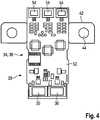
1 eine schematische Darstellung einer Schnellladesäule zum Schnellladen einer Batterie eines Fahrzeugs mit einem elektrischen Antrieb gemäß einer ersten, bevorzugten Ausführungsform in einer perspektivischen Ansicht,2 eine Darstellung einer Messeinrichtung zum Schnellladen einer Batterie eines Fahrzeugs mit einem elektrischen Antrieb gemäß einer ersten, bevorzugten Ausführungsform zusammen mit einer Auswerteeinheit in einer Draufsicht,3 eine funktionale Darstellung eines Innenbereichs der Messeinrichtung aus2 in Übereinstimmung mit der ersten Ausführungsform, und4 eine Innenansicht der Messeinrichtung aus2 mit Strommesseinrichtung und Spannungsmesseinrichtung, die auf einer Leiterplatte gemeinsam angeordnet sind, in Übereinstimmung mit der ersten Ausführungsform.
1 1 shows a schematic illustration of a quick charging column for quick charging a battery of a vehicle with an electric drive according to a first preferred embodiment in a perspective view,2nd 1 shows a top view of a measuring device for fast charging a battery of a vehicle with an electric drive according to a first preferred embodiment, together with an evaluation unit,3rd a functional representation of an interior of the measuring device2nd in accordance with the first embodiment, and4th an interior view of the measuring device2nd with current measuring device and voltage measuring device, which are arranged together on a circuit board, in accordance with the first embodiment.
Die
Die Ladesäule
Die Ladesäule
Die Messeinrichtung
Die Messeinrichtung
In dem Gehäuse
Eingangsseitig wird die Energieversorgungseinrichtung von den Stromleitern
Die Strommesseinrichtung
Die Messeinrichtung
An dem Shunt
Wie in
An einem Rand der Leiterplatte
Die Messeinrichtung
Das elektrische Verbindungselement
In einer alternativen Ausführungsform ist das elektrische Verbindungselement
Das elektrische Verbindungselement
Das metallische Blechelement
Die Ladeeinrichtung
ZITATE ENTHALTEN IN DER BESCHREIBUNG QUOTES INCLUDE IN THE DESCRIPTION
Diese Liste der vom Anmelder aufgeführten Dokumente wurde automatisiert erzeugt und ist ausschließlich zur besseren Information des Lesers aufgenommen. Die Liste ist nicht Bestandteil der deutschen Patent- bzw. Gebrauchsmusteranmeldung. Das DPMA übernimmt keinerlei Haftung für etwaige Fehler oder Auslassungen.This list of documents listed by the applicant has been generated automatically and is only included for the better information of the reader. The list is not part of the German patent or utility model application. The DPMA assumes no liability for any errors or omissions.
Zitierte PatentliteraturPatent literature cited
- US 2017129348 A1 [0011]US 2017129348 A1 [0011]
- US 2004169489 A1 [0012]US 2004169489 A1 [0012]
- US 2010076825 A1 [0013]US 2010076825 A1 [0013]
- US 2011258112 A1 [0014]US 2011258112 A1 [0014]
- US 2015346288 A1 [0015]US 2015346288 A1 [0015]
Claims (10)
Translated fromGermanPriority Applications (2)
| Application Number | Priority Date | Filing Date | Title |
|---|---|---|---|
| DE102018128783.6ADE102018128783B4 (en) | 2018-11-16 | 2018-11-16 | Measuring device for a charging device and charging device |
| CN201921940557.8UCN211731069U (en) | 2018-11-16 | 2019-11-11 | Measuring device and charging device for charging device |
Applications Claiming Priority (1)
| Application Number | Priority Date | Filing Date | Title |
|---|---|---|---|
| DE102018128783.6ADE102018128783B4 (en) | 2018-11-16 | 2018-11-16 | Measuring device for a charging device and charging device |
Publications (2)
| Publication Number | Publication Date |
|---|---|
| DE102018128783A1true DE102018128783A1 (en) | 2020-05-20 |
| DE102018128783B4 DE102018128783B4 (en) | 2024-06-06 |
Family
ID=70470411
Family Applications (1)
| Application Number | Title | Priority Date | Filing Date |
|---|---|---|---|
| DE102018128783.6AActiveDE102018128783B4 (en) | 2018-11-16 | 2018-11-16 | Measuring device for a charging device and charging device |
Country Status (2)
| Country | Link |
|---|---|
| CN (1) | CN211731069U (en) |
| DE (1) | DE102018128783B4 (en) |
Cited By (3)
| Publication number | Priority date | Publication date | Assignee | Title |
|---|---|---|---|---|
| CN114537179A (en)* | 2022-04-24 | 2022-05-27 | 南京存阳电力发展有限公司 | Wiring-free pre-assembled integrated non-motor vehicle charging terminal device |
| EP4032742A1 (en)* | 2021-01-25 | 2022-07-27 | Dr.Ing. h.c. F. Porsche Aktiengesellschaft | Method for testing a dc meter in a charging column and test bench for a charging column |
| EP4145140A1 (en)* | 2021-09-02 | 2023-03-08 | Lisa Dräxlmaier GmbH | Circuit board arrangement for measuring battery current of battery operated vehicle |
Citations (7)
| Publication number | Priority date | Publication date | Assignee | Title |
|---|---|---|---|---|
| US20040169489A1 (en) | 2003-02-28 | 2004-09-02 | Raymond Hobbs | Charger, vehicle with charger, and method of charging |
| US20100076825A1 (en) | 2008-09-25 | 2010-03-25 | Hitachi, Ltd. | Charge/discharge control apparatus |
| US20110258112A1 (en) | 2008-10-31 | 2011-10-20 | Leviton Manufacturing Company Inc. | System and method for charging a vehicle |
| DE102014202626A1 (en)* | 2014-02-13 | 2015-08-13 | Robert Bosch Gmbh | Battery management system for a battery with multiple battery cells and method |
| US20150346288A1 (en) | 2014-05-27 | 2015-12-03 | Power Measurements, LLC | Devices and methods for testing the energy measurement accuracy, billing accuracy, functional performance and safety of electric vehicle charging stations |
| US20170129348A1 (en) | 2015-11-09 | 2017-05-11 | Hyundai Motor Company | Vehicle and charging control method of the vehicle |
| DE202017102652U1 (en)* | 2017-05-04 | 2017-05-26 | Albrecht Jung Gmbh & Co. Kg | Mains outlet |
- 2018
- 2018-11-16DEDE102018128783.6Apatent/DE102018128783B4/enactiveActive
- 2019
- 2019-11-11CNCN201921940557.8Upatent/CN211731069U/enactiveActive
Patent Citations (7)
| Publication number | Priority date | Publication date | Assignee | Title |
|---|---|---|---|---|
| US20040169489A1 (en) | 2003-02-28 | 2004-09-02 | Raymond Hobbs | Charger, vehicle with charger, and method of charging |
| US20100076825A1 (en) | 2008-09-25 | 2010-03-25 | Hitachi, Ltd. | Charge/discharge control apparatus |
| US20110258112A1 (en) | 2008-10-31 | 2011-10-20 | Leviton Manufacturing Company Inc. | System and method for charging a vehicle |
| DE102014202626A1 (en)* | 2014-02-13 | 2015-08-13 | Robert Bosch Gmbh | Battery management system for a battery with multiple battery cells and method |
| US20150346288A1 (en) | 2014-05-27 | 2015-12-03 | Power Measurements, LLC | Devices and methods for testing the energy measurement accuracy, billing accuracy, functional performance and safety of electric vehicle charging stations |
| US20170129348A1 (en) | 2015-11-09 | 2017-05-11 | Hyundai Motor Company | Vehicle and charging control method of the vehicle |
| DE202017102652U1 (en)* | 2017-05-04 | 2017-05-26 | Albrecht Jung Gmbh & Co. Kg | Mains outlet |
Cited By (4)
| Publication number | Priority date | Publication date | Assignee | Title |
|---|---|---|---|---|
| EP4032742A1 (en)* | 2021-01-25 | 2022-07-27 | Dr.Ing. h.c. F. Porsche Aktiengesellschaft | Method for testing a dc meter in a charging column and test bench for a charging column |
| EP4145140A1 (en)* | 2021-09-02 | 2023-03-08 | Lisa Dräxlmaier GmbH | Circuit board arrangement for measuring battery current of battery operated vehicle |
| CN114537179A (en)* | 2022-04-24 | 2022-05-27 | 南京存阳电力发展有限公司 | Wiring-free pre-assembled integrated non-motor vehicle charging terminal device |
| CN114537179B (en)* | 2022-04-24 | 2023-07-18 | 南京存阳电力发展有限公司 | Wiring-free pre-installed integrated non-motor vehicle charging terminal equipment |
Also Published As
| Publication number | Publication date |
|---|---|
| CN211731069U (en) | 2020-10-23 |
| DE102018128783B4 (en) | 2024-06-06 |
Similar Documents
| Publication | Publication Date | Title |
|---|---|---|
| EP3684641B1 (en) | Measuring device and method for measuring electrical energy transferred from a charging station | |
| DE102018128783B4 (en) | Measuring device for a charging device and charging device | |
| DE102011101352A1 (en) | HV battery, in particular traction battery for a vehicle | |
| DE102017123457A1 (en) | Charger and vehicle with multiple charging interfaces | |
| DE102011083307A1 (en) | Device for measuring a battery current | |
| DE102008022787A1 (en) | Printed circuit board for detecting a voltage drop | |
| DE102017130509A1 (en) | current detection | |
| WO2015090926A1 (en) | Method for monitoring a battery, evaluation device and measurement system | |
| DE102006032763A1 (en) | Apparatus and method for measuring a current flowing in an electrical conductor | |
| DE112012006861B4 (en) | Battery charging system and method for wirelessly charging a battery | |
| DE102011079326A1 (en) | Method and apparatus for monitoring a ground connection | |
| DE102015012415B4 (en) | Prediction of a voltage drop in a motor vehicle | |
| EP3669199A1 (en) | Apparatus | |
| EP2710241B1 (en) | Storage vessel for a liquid | |
| DE102018128772A1 (en) | Measuring device with shielding for a charging device for charging a vehicle | |
| DE102020127773A1 (en) | Method and control device for determining a capacity of a battery cell arrangement of a motor vehicle and a motor vehicle equipped accordingly | |
| DE102018128787A1 (en) | Measuring device for a charging device for charging a vehicle | |
| EP3265832A1 (en) | Electrical assembly for measuring a current intensity of a direct-current circuit by means of the anisotropic magnetoresistive effect | |
| DE102020110190A1 (en) | Method for monitoring an electrical potential of an electrically operated vehicle and electronic monitoring system | |
| DE102019201759A1 (en) | Battery unit and method for operating a battery unit | |
| DE102018128773A1 (en) | Evaluation unit for a charging device for charging a vehicle | |
| DE102021123091A1 (en) | CIRCUIT BOARD ASSEMBLY FOR MONITORING A DRIVE BATTERY OF A BATTERY OPERATED VEHICLE | |
| DE102018204126A1 (en) | Charging systems for charging electrical energy storage devices of electric vehicles and associated methods | |
| EP2393152B1 (en) | Battery control device | |
| DE4225013A1 (en) | DEVICE FOR SUPPORTING THE FOREIGN ENERGY INPUT IN AN ELECTRICAL VEHICLE ON-LINE NETWORK |
Legal Events
| Date | Code | Title | Description |
|---|---|---|---|
| R012 | Request for examination validly filed | ||
| R016 | Response to examination communication | ||
| R016 | Response to examination communication | ||
| R018 | Grant decision by examination section/examining division | ||
| R020 | Patent grant now final |